
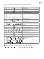
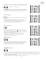
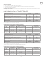
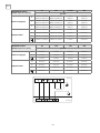
SPLIT-TYPE
AIR CONDITIONER
USER MANUAL
For R32 DC Inverter models:
TT26EX21-0932IA
TT26EX81-0932IAW
TT34EX21-1232IA
TT34EX81-1232IAW
TT34EXC1-1232IAWPC
TT51EX21-1832IA
TT51EX81-1832IAW
TT68EX21-2432IA
Ver. 2021
HU MKD
BIH/
MNE
RO SLO SRBENG BG GR HR

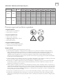
OPERATING INSTRUCTION
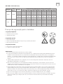
Note: All the pictures in this manual are just schematic diagrams, the actual is the standard. Please read
this owner’s manual carefully and thoroughly before operating the unit! Take care of this manual for future
reference.
UPUTE ZA UPOTREBU
Napomena: Sve slike u ovom priručniku su samo shematski dijagrami, fizički proizvod je standard. Molimo
Vas da pažljivo i temeljito pročitate ovo uputstvo za upotrebu prije korištenja uređaja! Čuvajte ovaj priručnik
za buduće korištenje.
FELHASZNÁLÓI KÉZIKÖNYV
Megjegyzés: A kézikönyvben található képek csak sematikus ábrák, az aktuális a szabvány. Kérjük, figyelmesen
olvassa el ezt a kézikönyvet mielőtt működtetné az eszközt! Őrizze meg ezt a kézikönyvet a későbbiekre is.
ΕΓΧΕΙΡΙΔΙΟ ΧΡΉΣΉΣ
Σημείωση: Οι εικόνες στο παρόν εγχειρίδιο είναι σχεδιαγράμματα, ανατρέξτε στο πραγματικό προϊόν. Διαβάστε
προσεκτικά τις προφυλάξεις στο παρόν εγχειρίδιο προτού θέσετε τη μονάδα σε λειτουργία! Φυλάξτε το παρόν
εγχειρίδιο για μελλοντική χρήση.
ИНСТРУКЦИЯ ЗА УПОТРЕБА
Забележка: Всички снимки в тази инструкция са само схематични диаграми, действителните са
стандартните. Моля, прочетете внимателно тази инструкция за употреба преди да започнете работа с
уреда! Запазете тази инструкция за бъдещи справки
PRIROČNIK ZA UPORABO
Opomba: Vse slike v tem priročniku so le shematske risbe, dejansko stanje je standard. Prosimo, da pred
uporabo skrbno in temeljito preberete ta priročnik za uporabo! Priročnik shranite za kasnejšo uporabo.
MANUAL DE UTILIZARE
Nota: Fotografiile din acest manual sunt doar diagrame schematice. Vă rugăm să citiți “Manualul de Utilizare”
cu atenție, înainte de a utiliza aerul condiționat, pentru a asigura funcționarea corespunzătoare. Păstrați
manualul pentru referințe ulterioare.
ENG
HR
HU
GR
BG
UPUTSTVO ZA UPOTREBU
Napomena: Sve slike u ovom priručniku su samo šematski dijagrami, fizički proizvod je standard. Molimo Vas
da pažljivo i temeljno pročitate ovo uputstvo za upotrebu prije korišćenja uređaja! Sačuvajte ovo uputstvo za
buduću upotrebu.
BIH/
MNE
SLO
RO
УПАТСТВО ЗА УПОТРЕБА
Напомена: Сите слики во овој прирачник се само шематски дијаграми, физичкиот производ е
стандард. Ве молиме внимателно и теменлно да го причитате ова упатство за употреба пред
користење на уредот! Сочувајте го ова упатство за идна употреба.
MKD
UPUTSTVO ZA UPOTREBU
Napomena: Sve slike u ovom priručniku su samo šematski dijagrami, fizički proizvod je standard. Molimo
Vas da pažljivo i temeljno pročitate ovo uputstvo za upotrebu pre korišćenja uređaja! Sačuvajte ovo
uputstvo za buduću upotrebu.
SRB

3
ENG
• Read this guide before installing and using the appliance.
• During the installation of the indoor and outdoor units the access to the working area should be forbidden to
children. Unforeseeable accidents could happen.
• Make sure that the base of the outdoor unit is firmly fixed.
• Check that air cannot enter the refrigerant system and check for refrigerant leaks when moving the air
conditioner.
• Carry out a test cycle after installing the air conditioner and record the operating data.
• The ratings of the fuse installed in the built in control unit are 4A / 250V .
• Protect the indoor unit with a fuse of suitable capacity for the maximum input current or with another overload
protection device.
• Ensure that the mains voltage corresponds to that stamped on the rating plate. Keep the switch or power plug
clean. Insert the power plug correctly and firmly into the socket, thereby avoiding the risk of electric shock or
fire due to insufficient contact.
• Check that the socket is suitable for the plug , otherwise have the socket changed.
• The appliance must be fitted with means for disconnection from the supply mains having a contact separation
in all poles that provide full disconnection under overvoltage category III conditions, and these means must be
incorporated in the fixed wiring in accordance with the wiring rules.
• The air conditioner must be installed by professional or qualified persons.
• Do not install the appliance at a distance of less than 50 cm from inflammable substances (alcohol, etc.) or from
pressurised containers (e.g. spray cans).
• If the appliance is used in areas without the possibility of ventilation, precautions must be taken to prevent any
leaks of refrigerant gas from remaining in the environment and creating a danger of fire
• The packaging materials are recyclable and should be disposed of in the separate waste bins .Take the air
conditioner at the end of its useful life to a special waste collection centre for disposal.
• Only use the air conditioner as instructed in this booklet. These instructions are not intended to cover every
possible condition and situation . As with any electrical household appliance , common sense and caution are
therefore always recommended for installation, operation and maintenance.
• The appliance must be installed in accordance with applicable national regulations.
• Before accessing the terminals , all the power circuits must be disconnected from the power supply.
• The appliance shall be installed in accordance with national wiring regulations.
• This appliance can be used by children aaged from 8 years and above and persons with reduced physical,
sensory or mental capabilities or lack of experience and knowledge if they have been given supervision or
instruction concerning use of the appliance in a safe way and understand the hazards involved. Children shall
not play with the appliance. Cleaning and user maintenance shall not be made by children without supervision.
• Do not try to install the conditioner alone; always contact specialized technical personnel.
• Cleaning and maintenance must be carried out by specialized technical personnel. In any case disconnect the
appliance from the mains electricity supply before carrying out any cleaning or maintenance.
• Ensure that the mains voltage corresponds to that stamped on the rating plate. Keep the switch or power plug
clean. Insert the power plug correctly and firmly into the socket , thereby avoiding the risk of electric shock or
fire due to insufficient contact.
• Do not pull out the plug to switch off the appliance when it is in operation, since this could create a spark and
cause a fire, etc.
• This appliance has been made for air conditioning domestic environments and must not be used for any other
purpose , such as for drying clothes, cooling food, etc.
• The packaging materials are recyclable and should be disposed of in the separate waste bins . Take the air
conditioner at the end of its useful life to a special waste collection center for disposal.
SAFETY RULES AND RECOMMENDATIONS
FOR THE INSTALLER
SAFETY RULES AND RECOMMENDATIONS
FOR THE USER

4
ENG
• Always use the appliance with the air filter mounted . The use of the conditioner without air filter could cause an
excessive accumulation of dust or waste on the inner parts of the device with possible subsequent failures.
• The user is responsible for having the appliance installed by a qualified technician , who must check that it is
earthed in accordance with current legislation and insert a thermomagnetic circuit breaker.
• The batteries in remote controller must be recycled or disposed of properly. Disposal of Scrap Batteries ---
Please discard the batteries as sorted municipal waste at the accessible collection point.
• Never remain directly exposed to the flow of cold air for a long time. The direct and prolonged exposition
to cold air could be dangerous for your health .Particular care should be taken in the rooms where there are
children , old or sick people.
• If the appliance gives off smoke or there is a smell of burning, immediately cut off the pow er supply and contact
the Service Centre.
• The prolonged use of the device in such conditions could cause fire or electrocution.
• Have repairs carried out only by an authorised Service Centre of the manufacturer . Incorrect repair could
expose the user to the risk of electric shock, etc.
• Unhook the automatic switch if you foresee not to use the device for a long time. The airflow direction must be
properly adjusted.
• The flaps must be directed downwards in the heating mode and upwards in the cooling mode.
• Only use the air conditioner as instructed in this booklet. These instructions are not intended to cover every
possible condition and situation. As with any electrical household appliance, common sense and caution are
therefore always recommended for installation , operation and maintenance.
• Ensure that the appliance is disconnected from the power supply when it will remain inoperative for a long
period and before carrying out any cleaning or maintenance.
• Selecting the most suitable temperature can prevent damage to the appliance.
• Do not bend, tug or compress the power cord since this could damage it. Electrical shocks or fire are probably
due to a damaged power cord. Specialized technical personnel only must replace a damaged power cord.
• Do not use extensions or gang modules.
• Do not touch the appliance when barefoot or parts of the body are wet or damp.
• Do not obstruct the air inlet or outlet of the indoor or the outdoor unit. The obstruction of these openings
causes a reduction in the operative efficiency of the conditioner with possible consequent failures or damages.
• In no way alter the characteristics of the appliance.
• Do not install the appliance in environments where the air could contain gas , oil or sulphur or near sources of
heat.
• This appliance is not intended for use by persons (including children ) with reduced physical, sensory or mental
capabilities, or lack of experience and knowledge, unless they have been given supervision or instruction
concerning use of the appliance by a person responsible for their safety.
• Do not climb onto or place any heavy or hot objects on top of the appliance.
• Do not leave windows or doors open for long when the air conditioner is operating.
• Do not direct the airflow onto plants or animals.
• A long direct exposition to the flow of cold air of the conditioner could have negative effects on plants and
animals.
• Do not put the conditioner in contact with water. The electrical insulation could be damaged and thus causing
electrocution.
• Do not climb onto or place any objects on the outdoor unit
• Never insert a stick or similar object into the appliance. It could cause injury.
• Children should be supervised to ensure that they do not play with the appliance. If the supply cord is damaged,
it must be replaced by the manufacturer,its service agent or similarly qualified persons in order to avoid a
hazard.
SAFETY RULES AND PROHIBITIONS

5
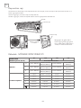
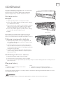
ENG
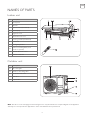
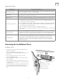
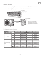
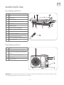
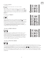
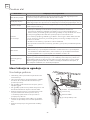
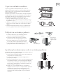
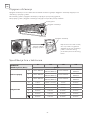
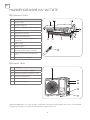
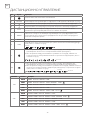
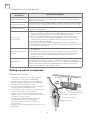
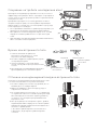
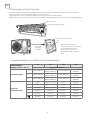
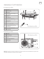
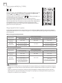
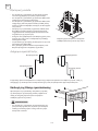
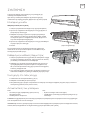
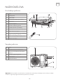
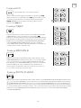
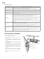
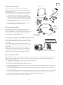
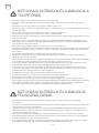
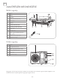
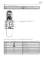
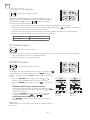
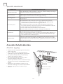
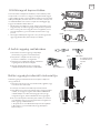
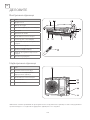
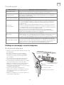
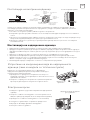
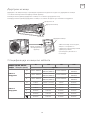
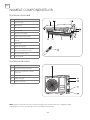
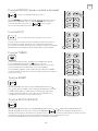
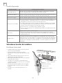
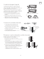
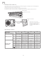
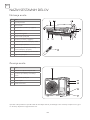
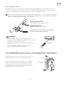
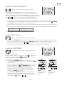
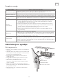
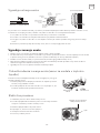
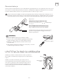
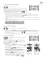
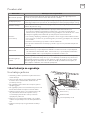
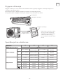
NAMES OF PARTS
Indoor unit
Outdoor unit
Note: The above or the next pages mentioned figures are only intended to be a simple diagram of the appliance
and may not correspond to the appearance of the units that have been purchased.
No. Description
1 Front panel
2 Air filter
3 Optional filter (if installed)
4 LED Display
5 Signal receiver
6 Terminal block cover
7 Ionizer generator(if installed)
8 Deflectors
9 Emergency button
10
Indoor unit rating label (Stick
position optional)
11 Airflow direction louver
12 Remote controller
No. Description
13 Air outlet grille
14 Outdoor unit rating label
15 Terminal block cover
16 Gas valve
17 Liquid valve

6
ENG
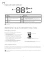
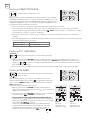
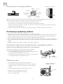
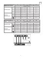
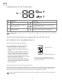
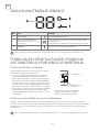
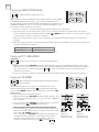
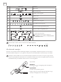
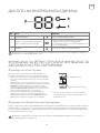
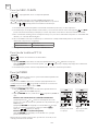
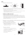
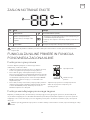
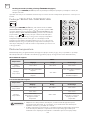
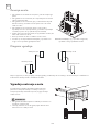
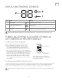
INDOOR UNIT DISPLAY
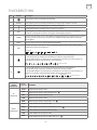
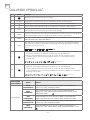
EMERGENCY & AUTO-RESTART FUNCTION
Emergency function
Auto-restart function
No. Led Function
1 SLEEP
SLEEP mode
2
Temperature display (if present) /
Error code
1. Lights up during Timer operation when the air
conditioner is operational
2. Displays the malfunction code when fault occurs.
3 TIMER
Lights up during Timer operation.
The shape and position of switches and indicators may be different according to the model, but their function
is the same.
The shape and position of the emergency button may be different according to the model, but their function
is the same.
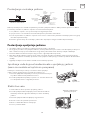
If the remote controller fails to work or maintenance
necessary, proceed as following:
• Open and lift the front panel up to an angle to reach
the emergency button.
• For heating model, press the emergency button
at first time, the unit will operate in COOL mode.
Press at second time within 3 seconds, the unit will
operate in HEATmode. Press at third time after 5
seconds, the unit will turn off.
• For cooling only model, press the emergency
button at first time, the unit will operate in COOL
mode. Press again, the unit will turn off.
The appliance is preset with an auto-restart function. In case of a sudden power failure, the module will memorizes
the setting conditions before the power failure. When the power restores, the unit will restart automatically with the
previous settings preserved by the memory function.
front panel
Emergency button
The emergency button is located on E-box cover
of the unit under the front panel.

7
ENG
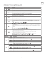
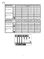
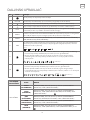
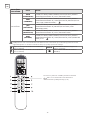
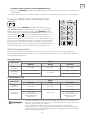
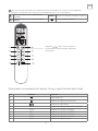
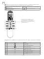
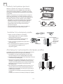
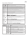
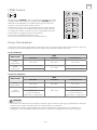
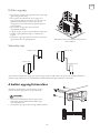
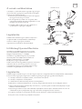
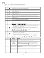
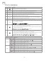
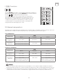
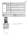
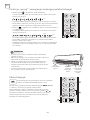
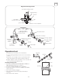
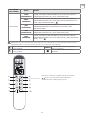
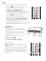
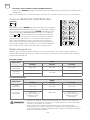
REMOTE CONTROLLER
No. Button Function
1
To turn on or off the air conditioner .
2 OPTION To activate or deactivate optional function (Check below table).
3
To decrease temperature, time setting or choose the function.
4
To increase temperature , time setting or choose the function.
5 ECO
To activate / deactivate the ECO function which enables the unit automatically to sets the
operation to achieve energy savings.
6 TURBO
Press this button to activate/deactivate the Superfunction which enables the unit to reach
the preset temperature in the shortest time.
7 MODE To select the mode of operation (AUTO COOL DRY FAN HEAT)
8 FAN
To select the fan speed of auto/mute/low/mid/mid/high/high/turbo , cycle as below
Flashing
9
1. If press time interval is over 2 seconds, to activate the swing of vertical flap(left/right)
or deactivate it.
2. If press time interval is in 2 seconds, the swing angle range of vertical flap will cycle as
below.
deactivate
10
1. If press time interval is over 2 seconds, to activate the swing of horizontal
deflectors(left/right) or deactivate it.
2. If press time interval is in 2 seconds, the swing angle range of horizontal
deflectors(left/right) will cycle as below.
deactivate
Flashing
ON/OFF Mode OPTIONS
ON
AUTO TIMER DISPLAY HEALTH I FEEL
COOL
TIMER DISPLAY HEALTH SLEEP MILDEW I FEEL
DRY TIMER DISPLAY HEALTH MILDEW I FEEL
FAN TIMER DISPLAY HEALTH I FEEL
HEAT
TIMER DISPLAY HEALTH SLEEP I FEEL 8°C H
OFF
AUTO CLEAN TIMER DISPLAY HEALTH I FELL
COOL
CLEAN TIMER DISPLAY HEALTH SLEEP MILDEW I FEEL
DRY CLEAN TIMER DISPLAY HEALTH MILDEW I FEEL
FAN CLEAN TIMER DISPLAY HEALTH I FEEL
HEAT
CLEAN TIMER DISPLAY HEALTH SLEEP I FEEL 8°C H

8
ENG
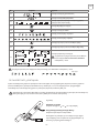
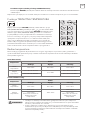
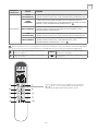
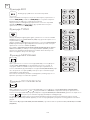
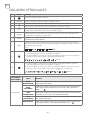
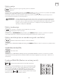
Meaning of symbols on the liquid crystal display
Optional Function: COMFORTABLE COOLING
airflow
HEALTH Optional Function: generate the ionizer
Optional Function: COMFORTABLE HEATING
airflow
button: SWING LEFT/RIGHT
Hold and together over 3 seconds
to activate of deactivate the Lock function
You will hear a beep when you press the following buttons or select the following optional functions, though
the actual model haven’t this function, we express our apologies:
No. Symbols Meaning
1
Single indicator
2
Lock function indicator
3
Battery indicator
4 AUTO Mode Auto function indicator
5 COOL Mode Cooling indicator
6 DRY Mode Dry indicator
7 FAN Mode Fan indicator
8 HEAT Mode Heating indicator
9 ECO ECO function indicator

9
ENG
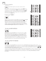
The following angle can not be selected for current models, we express our apologies.
Use 2 LRO 3 AAA (1.5V) batteries . Do not use rechargeable batteries . Replace the old batteries with new
ones of the same type when the display is no longer legible. Do not dispose batteries as unsorted municipal
waste. Collection of such waste separately for special treatment is necessary.
Replacement of Batteries
Remove the battery cover plate from the rear of the remote controller, by sliding it in the direction of the arrow.
Install the batteries according the direction (+and -) shown on the Remote Controller. Reinstall the battery cover by
sliding it into place.
No. Symbols Meaning
10
TIMER
Timer indicator
11
Temperature indicator
12
Flashing
Fan speed indicator: Auto low low mid mid high
13
Mute indicator
14
SUPER indicator
15
Flap swing angle indicator
16
Flashing
Deflector swing angle indicator
17
Comfortable cooling airflow indicator
18
Comfortable heating airflow indicator
19
Optional functions indicator
Notes: There is no HEALTH/WIND FREE/
GEN MODE functions for current models, we
express our apologies.
Flashing
Note:
Child-lock:
Press
and together to activate
Display ON/OFF:
Long press ECO button
Please remove batteries to avoid leakage damage
when not using for a long time.

10
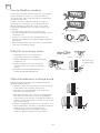
ENG
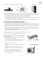
WARNING!
1. Direct the remote controller toward the Air conditioner.
2. Check that there are no objects between the remote control
and the Signal receptor in the indoor unit.
3. Never leave the remote controller exposed to the rays of the
sun.
4. Keep the remote controller at a distance of at least 1m from
the television or other electrical appliances.
• This adjustment must be done while the appliance is
switched off.
• Never position ”Flaps” manually, the delicate mechanism
might seriously damaged!
• Never poke fingers, sticks or other objects in the air inlet or
outlet vents. Such accidental contact with live pants might
cause unforeseeable damage or hurt.
• The following angle can not be selected for current models,
we express our apologies.
flashing
Signal receptor
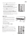
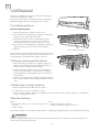
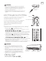
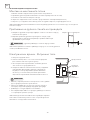
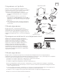
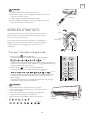
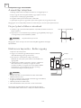
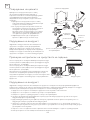
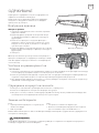
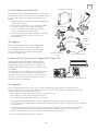
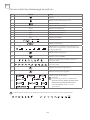
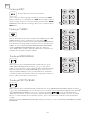
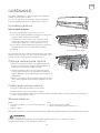
OPERATING INSTRUCTIONS
“Swing” control of the air flow
The air sucked by the fan enters from the grill and passes
through the filter, then it is cooled/dehumidified or heated
through the heat exchanger.
The direction of the air outlet is motorized up and down by
flaps, and manually moved right and left by the vertical
deflectors, for some models, the vertical deflectors could be
controlled by motor as well.
1. Press the button
to activate the FLAP ,
1. If press time interval is in 2 seconds, the swing will cycle as below
deactivate
2. If press time interval is over 2 seconds, it will be deactivate the air flow
is directed alternatively from up to down .In order to guarantee an even
diffusion of the air in the room.
2. Press the button
to activates the motorized deflectors
1. If press time interval is in 2 seconds the swing will cycle as below
deactivate
flashing
2. If press time interval is over 2 seconds, it will be deactivate the air flow
is directed alternatively from left to right. (Optional function, depends
on the models).
The deflectors are positioned manually and placed under the flaps.
They allow to direct the air flow rightward or leftward.
Filter
Heat
Exchanger
Fan
“flaps”
“flap”
movement
Deflectors
WARNING!

11
ENG
Cooling mode
Heating mode
Dry mode
Fan mode (not FAN button)
Auto mode
To activate the cooling function (COOL) , press the MODE button until
the symbol COOL appears on the display.
The cooling function is activated by setting the button
or at a
temperature lower than that of the room.
To optimize the function of the Air conditioner, adjust the temperature
(1), the speed (2) and the direction of the air flow (3) by pressing the
button indicated.
To activate the heating function (HEAT) , press the MODE button until the symbol HEAT appears on the display.
With the button
or set a temperature higher than that of the room.
To optimize the function of the Air conditioner adjust the temperature (1), the speed (2) and the direction of the air
flow (3) by pressing the button indicated.
To set the DRY mode, Press MODE until DRY appears in the display. An automatic function of alternating cooling
cycles and air fan is activated.
To set the FAN mode, Press MODE until FAN appears on the display.
To activate the AUTO mode of operation, press the MODE button on the remote controller until the symbol
AUTO appears on the display. In AUTO mode , the air conditioner will run automatically according to the room
temperature.
In HEATING operation, the appliance can automatically activate a defrost cycle, which is
essential to clean the frost on the condenser so as to recover its heat exchange function.
This procedure usually lasts for 2-10 minutes during defrosting,indoor unit fan stop
operation. After defrosting ,it resumes to HEATING mode automatically.
WARNING!
The cooling function allows the air condit- ioner to cool
the room and at the same time reduces Air humidity.
The heating function allows the air conditi- oner to heat
the room.
This function reduces the humid- ity of the air to make the
room more comfortable.
The air conditioner works in only ventilation.
Automatic mode.

12
ENG
Display function (indoor display)
ECO function
Turbo function
Sleep function
Mildew function
Press OPTION at the fist time, select the DISPLAY by pressing the
button
or until symbol DISPLAY is flashing; Press OPTION again to
switch off the LED display on the panel, and
appears on the
remote controller display. Do it again to switch on the LED display.
Only in Heating or Cooling model, press ECO button and symbol
ECO will appear on the display, the air conditioner will work in energy
saving process. To cancel this function, pressing the MODE to switch
other mode or pressing the ECO button again.
To activate turbo function,pressing the button TURBO or pressing the
button FAN until symbol
appears on the display.
To cancel this function, pressing the FAN to switch other fan speed or
pressing the TURBO button again.
In AUTO/HEAT/COOL/FAN mode, When you select TURBO feature, it
will use the highest fan setting to blow strong airflow.
Press OPTION at the fist time , select the SLEEP by pressing the button
or until symbol SLEEP is flashing; Press OPTION again to activate
the SLEEP function, and SLEEP appears on the display. Do it again to
deactivate this function. After 10 hours running in sleep mode, the air
conditioner will return to the previous setting mode.
Press OPTION at the fist time , select the MILDEW by pressing the button
or until symbol MILDEW is flashing;
Press OPTION again to activate the MILDEW function, and
appears on the display. Do it again to
deactivate this function. This function enable the air conditioner still blow airflow about 15 minutes to dry the
indoor inner parts to avoid mildew, when the air conditioner is off.
Note: MILDEW function only available in DRY/COOLING mode
Switch on/off the LED display on panel
The air conditioner works in economic mode

13
ENG
Self-clean function
Timer function
8°C heating function
Press OPTION at the fist time , select the CLEAN by pressing the
button
or until symbol CLEAN is flashing; Press OPTION again to
activate the CLEAN function, and
appears on the display. Do it
again to deactivate this function.
For timer on, before proceeding with the time: Switch the conditioner
off (with the key
). program the working mode with the button
MODE and the fan speed with the button FAN.
Timer setting/change/cancel:
1. Press OPTION at the fist time, select the Timer by pressing the
button
or until symbol TIMER is flashing;
2. Press OPTION again, the data symbol like
and TIMER will
be flashing;
3. To set the timer orchange the timer:
(1) Press the button
or to set the expected timer (Increase or
decrease at half-hour intervals) the symbols and TIMER both are
flashing.
(2) Press OPTION or wait for 5 seconds without any operation
to confirm the timer, the pre-setting timer like
and symbol
will be on the display.
To cancel the timer (if TIMER is on)
Press OPTION or wait for 5 seconds without any operation to
cancel the timer .
Note: All processing should be operated in 5 seconds, otherwise the
processing will be cancelled.
1. Press OPTION at the first time, select the 8°C H by pressing the button
or until symbol 8°C H is flashing;
Press OPTION again to activate the 8°C heating function, and
appears on the display. Do it again or
change the mode to deactivate this function.
2. This function enable the setting temperature 8°C when heating.
1. This function help carry away the accumulated dirt, bacteria, etc from the evaporator.
2. This function will run about 30 minutes, and it will return to the pre-setting mode .You can press
or MODE
to cancel this function during the process. You will hear 2 beeps when it’s finished or cancelled.
3. It’s normal if there are some noise during this function process, as plastic materials expand with heat and
contract with cold.
4. We suggest operate this function as the following ambient condition to avoid certain safety protection
features.
Indoor unit Temp<30°C
Outdoor unit 5°C <Temp<30°C
5. We suggest operate this function per 3 months.
Switch off the air conditioner.
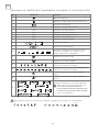
To set the automatic switch-on /off of the air conditioner
Only can be set in Heating mode
Figure 1
Timer-on
when switch off
Figure 2
Timer-off
when switch on

14
ENG
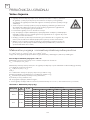
Temperature
Mode
Cooling operating Heating operating Drying operating
Room
temperature
17°C~32°C 0°C~27°C 17°C~32°C
Outdoor
temperature
15°C~43°C for T1 Climate
-7°C~24°C
15°C~43°C for T1 Climate
15°C~52°C for T3 Climate 15°C~52°C for T3 Climate
Temperature
Mode
Cooling operating Heating operating Drying operating
Room
temperature
17°C~32°C 0°C~30°C 17°C~32°C
Outdoor
temperature
15°C~53°C
-20°C~30°C
15°C~53°C
-15°C~53°C
For models with low
temperature cooling system
-15°C~53°C
For models with low
temperature cooling system
I FEEL function
Operating Temperature
Press OPTION at the fist time , select the I FEEL by pressing the button
or until symbol I FEEL is flashing; Press OPTION again to activate
the I FEEL function, and I
appears on the display. Do it again to
deactivate this function.
This function enable the remote control to measure the temperature
at its current location and send this signal 7 times in 2 hours to the air
conditioner to enable the air conditioner to optimize the temperature
around you and ensure maximum comfort. It will automatically
deactivate 2 hours later , or indoor temperature exceed the range
0~50°C.
The air conditioner is programmed for comfortable and suitable living conditions as below if used outside the
conditions, certain safety protection features might come into effect.,
Fix air conditioner:
Inverter air conditioner:
• The unit does not operate immediately if it is turned on after being turned off or after changing the mode
during operation.This is a normal self-protection action,you need waiting for about 3 minutes.
• The capacity and efficiency are according to the test conducted at full-load operation(The highest speed of
indoor fan motor and the maximum open angle of the flaps and deflectors are requested.)
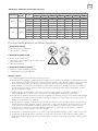
WARNING!

15
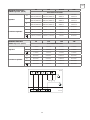
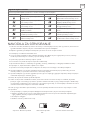
ENG
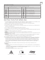
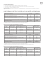
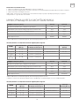
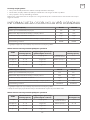
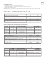
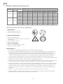
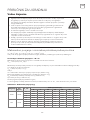
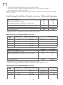
Category
LFL
(kg/m
3
)
h
0
(m)
Floor area (m
2
)
4 7 10 15 20 30 50
R290 0.038
0.6 0.05 0.07 0.08 0.1 0.11 0.14 0.18
1 0.08 0.11 0.13 0.16 0.19 0.2 0.3
1.8 0.15 0.2 0.24 0.29 0.34 0.41 0.53
2.2 0.18 0.24 0.29 0.36 0.41 0.51 0.65
R32 0.306
0.6 0.68 0.9 1.08 0.32 1.53 1.87 2.41
1 1.14 1.51 1.8 2.2 2.54 3.12 4.02
1.8 2.05 2.71 3.24 3.97 4.58 5.61 7.254
2.2 2.5 3.31 3.96 4.85 5.6 6.86 8.85
Table GG.1 - Maximum charge (kg)
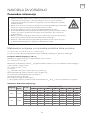
INSTALLATION MANUAL
Important considerations
• The air conditioner you buy must be installed by professional personnel and the
Installation manual is used only for the professional installation personnel! The
installation specifications should be subject to our after-sale service regulations.
• When filling the combustible refrigerant, any of your rude operations may cause serious
injury or injuries to human body or bodies and object or objects.
• A leak test must be done after the installation is completed.
• It is a must to do the safety inspection before maintaining or repairing an air conditioner
using combustible refrigerant in order to ensure that the fire risk is reduced to minimum.
• It is necessary to operate the machine under a controlled procedure in order to ensure
that any risk arising from the combustible gas or vapor during the operation is reduced
to minimum.
• Requirements for the total weight of filled refrigerant and the area of a room to be
equipped with an air conditioner (are shown as in the following Tables GG.1 and GG.2)
The maximum charge and the required minimum floor area
m
1
= (4 m
3
) x LFL , m
2
= (26 m
3
) x LFL, m
3
= (130 m
3
) x LFL
Where LFL is the lower flammable limit in kg/m
3
, R290 LFL is 0.038 kg/ m
3
, R32 LFL is 0.038 kg/m
3
.
For the appliances with a charge amount m
1
< M = m
2
:
The maximum charge in a room shall be in accordance with the following:
m
max
= 2.5 x (LFL)
(5/4)
x h
0
x (A)
1/2
The required minimum floor area A
min
to install an appliance with refrigerant charge M (kg) shall be in accordance
with following:
A
min
= (M/ (2.5 x (LFL)
(5/4)
x h
0
))
2
Where:
m
max
is the allowable maximum charge in a room, in kg;
M is the refrigerant charge amount in appliance, in kg;
A
min
is the required minimum room area, in m
2
;
A is the room area, in m
2
;
LFL is the lower flammable limit, in kg/m
3
;
h
0
is the installation height of the appliance,in meters for calculating m
max
or A
min
, 1.8 m for wall mounted.

16
ENG
Category
LFL
(kg/m
3
)
h
0
(m)
Charge amount (M) (kg) Minimum room area (m
2
)
4 7 10 15 20 30 50
R290 0.038
0.152kg 0.228kg 0.304kg 0.456kg 0.608kg 0.76kg 0.988kg
0.6 82 146 328 584 912 1514
1 30 53 118 210 328 555
1.8 9 16 36 65 101 171
2.2 6 11 24 43 68 115
R32 0.306
1.224kg 1.836kg 2.448kg 3.672kg 4.896kg 6.12kg 7.956kg
0.6 29 51 116 206 321 543
1 10 19 42 74 116 196
1.8 3 6 13 23 36 60
2.2 2 4 9 15 24 40
Table GG.2 - Minimum room area (m
2
)
Installation Safety Principles
1. Site Safety
2. Operation Safety
3. Installation Safety
• Open Flames Prohibited
• Ventilation Necessary
• Mind Static Electricity
• Must wear protective clothing and anti-static gloves
• Don`t use mobile phone
• Refrigerant Leak Detector
• Appropriate Installation Location
Please note that:
1. The installation site should be in a well-ventilated condition.
2. The sites for installing and maintaining an air conditioner using Refrigerant R290 should be free from open fire
or welding, smoking, drying oven or any other heat source higher than 370 which easily produces open fire;
the sites for installing and maintaining an air conditioner using Refrigerant R32 should be free from open fire
or welding, smoking, drying oven or any other heat source higher than 548 which easily produces open fire.
3. When installing an air conditioner, it is necessary to take appropriate anti-static measures such as wear anti-
static clothing and/or gloves.
4. It is necessary to choose the site convenient for installation or maintenance wherein the air inlets and outlets
of the indoor and outdoor units should be not surrounded by obstacles or close to any heat source or
combustible and/or explosive environment.
5. If the indoor unit suffers refrigerant leak during the installation, it is necessary to immediately turn off the valve
of the outdoor unit and all the personnel should go out till the refrigerant leaks completely for 15 minutes. If
the product is damaged, it is a must to carry such damaged product back to the maintenance station and it is
prohibited to weld the refrigerant pipe or conduct other operations on the user’s site.
6. It is necessary to choose the place where the inlet and outlet air of the indoor unit is even.
7. It is necessary to avoid the places where there are other electrical products, power switch plugs and sockets,
kitchen cabinet, bed, sofa and other valuables right under the lines on two sides of the indoor unit.

17
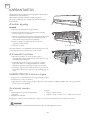
ENG
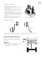
Special Tools
Indoor unit
• Install the indoor unit on a strong wall that is not
subject to vibrations.
• The inlet and outlet ports should not be
obstructed:the air should be able to blow all over
the room.
• Do not install the unit near a source of heat,
steam,or flammable gas.
• Do not install the unit where it will be exposed to
direct sunlight.
• Select a site where the condensed water can be
easily drained out, and where it is easily connected
to outdoor unit.
• Check the machine operation regularly and reserve
the necessary spaces as shown in the picture.
• Select a place where the filter can be easily taken
out.
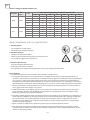
Tool Name Requirement(s) for Use
Mini Vacuum Pump
It should be an explosion-proof vacuum pump; can ensure certain precision and
its vacuum degree should be lower than 10Pa.
Filling Device
It should be a special explosion-proof filling device; have certain precision and its
filling deviation should be less than 5g.
Leak Detector It should be calibrated regularly; and its annual leak rate should not exceed 10g.
Concentration Detector
A. The maintenance site should be equipped with a fixed-type combustible
refrigerant concentration detector and connected to a safeguard alarm system;
its error must be not more than 5%.
B. The installation site should be equipped with a portable combustible refrigerant
concentration detector which can realize two-level audible and visual alarm; its
error must be not more than 10%.
C. The concentration detectors should be calibrated regularly.
D. It is necessary to check and confirm the functions before using the concentration
detectors.
Pressure Gauge
A. The pressure gauges should be calibrated regularly.
B. The pressure gauge used for Refrigerant 22 can be used for Refrigerants R290
and R161; the pressure gauge used for R410A can be used for Refrigerant 32.
Fire Extinguisher
It is necessary to carry fire extinguisher(s) when installing and maintaining an
air conditioner. On the maintenance site, there should be two or more kinds
of dry powder, carbon dioxide and foam fire extinguishers and that such fire
extinguishers should be placed at stipulated positions, with eye-catching labels
and in handy places.
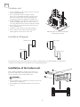
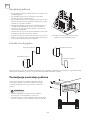
Selecting the Installation Place
Mounting plate
Condensed water
drain pipe
Sleeve
Insulating covering
Electrical cable
Water drain pipe

18
ENG
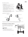
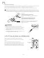
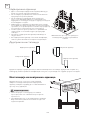
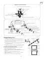
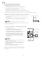
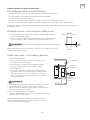
Outdoor unit
Installation Diagram
• Do not install the outdoor unit near sources of heat,
steam or flammable gas.
• Do not install the unit in too windy or dusty
places. Do not install the unit where people often
pass.Select a place where the air discharge and
operating sound will not disturb the neighbours.
• Avoid installing the unit where it will be exposed
to direct sunlight ( other wise use a protection , if
necessary, that should not interfere with the air flow).
• Reserve the spaces as shown in the picture for the
air to circulate freely.
• Install the outdoor unit in a safe and solid place.
• If the outdoor unit is subject to vibration, place
rubber gaskets onto the feet of the unit.
Before starting installation, decide on the position of
the indoor and outdoor units, taking into account the
minim- um space reserved around the units
Minimum space to be reserved (mm)
showing in the picture
Outdoor unit
Outdoor unit
Indoor unit
Indoor unit
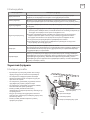
The purchaser must ensure that the person and/or company who is to install, maintain or repair this air
conditioner has qualifications and experience in refrigerant products.
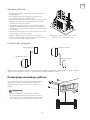
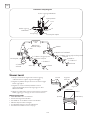
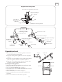
Installation of the Indoor unit
• Do not install your air conditioner in a wet room such as
a bathroom or laundry etc
• The installation site should be 250cm or more above
the floor.
WARNING!

19
ENG
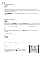
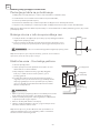
1. Make the piping hole (ɸ65) in the wall at a slight downward slant to the
outdoor side.
2. Insert the piping-hole sleeve into the hole to prevent the connection
piping and wiring from being damaged when passing through the hole.
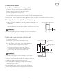
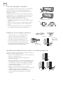
1. Open the front panel.
2. Take off the cover as indicated in the piciure ( by
removing a screw or breaking the hooks).
3. For the electrical connections, see the circuit diagram on
the right part of the unit under the front panel.
4. Connect the cable wires to the screw terminals by
following the numbering ,Use wire size suitable to
the electric power input (see name plate on the unit)
and according to all current national safety code
requirements.
To install, proceed as follows:
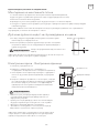
Installation of the mounting plate
Drilling a hole in the wall for the piping
Electrical connections-Indoor unit
• The cable connecting the outdoor and indoor units must be
suitable for outdoor use.
• The plug must be accessible also after the appliance has been
installed so that it can be pulled out if necessary.
• An efficient earth connection must be ensured.
• If the power cable is damaged, it must be replaced by an
authorised Service Centre.
Note: Optional the wires can been connected to the main PCB
of indoor unit by manufacturer according to the model without
terminal block.
The hole must slope downwards towards the exterior
Note: Keep the drain pipe down towards the direction of the wall hole,
otherwise leakage may occur
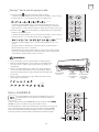
1. Always mount the rear panel horizontally and vertically
2. Drill 32 mm deep holes in the wall to fix the plate;
3. Insert the plastic anchors into the hole;
4. Fix the rear panel on the wall with provided tapping screws
5. Be sure that the rear panel has been fixed firmly enough to withstand the weight
Note: The shape of the mounting plate may be different from the one above, but installation method is similar .
WARNING!
WARNING!
Front panel
Wiring diagram
Terminal block
cover
Indoors Outdoors

20
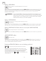
ENG
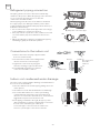
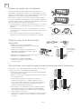
The piping can be run in the 3 directions indicated by
numbers in the picture . When the piping is run in direction
1or 3, cut a notch along the groove on the side
of the indoor unit with a cutter.
Run the piping in the direction of the wall hole and bind
the copper pipes , the drain pipe and the power cables
together with the tape with the drain pipe at the bottom, so
that water can flow freely.
• Do not remove the cap from the pipe until connecting it,
to avoid dampness or dirt from entering.
• If the pipe is bent or pulled too often , it will become stiff
. Do not bend the pipe more than three times at one
point.
• When extending the rolled pipe, straighten the pipe by
unwinding it gently as shown in the picture.
1. Remove the indoor unit pipe cap (check that
there is no debris inside).
2. Insert the fare nut and create a flange at the
extreme end of the connection pipe.
3. Tighten the connections by using two
wrenches working in opposite directions.
4. For R32/R290 refrigerants, mechanical
connectors should be outdoors.
The indoor unit condensed water drainage is fundamental for
the success of the installation.
1. Place the drain hose below the piping, taking care not to
create siphons.
2. The drain hose must slant downwards to aid drainage.
3. Do not bend the drain hose or leave it protruding
or twisted and do not put the end of it in water. If an
extension is connected to the drain hose, ensure that it is
lagged when it passes into the indoor unit.
4. If the piping is installed to the right, the pipes, power
cable and drain hose must be lagged and secured onto
the rear of the unit with a pipe connection.
1. Insert the pipe connection into the relative slot.
2. Press to join the pipe connection to the base.
Refrigerant piping connection
Connections to the indoor unit
Indoor unit condensed water drainage
Shape the connection pipe
Extending the rolled pipe
YES
NO
YES
NO NO
Torque wrench
The connectors
should be
outdoors
Indoors Outdoors
Pagina se încarcă...
Pagina se încarcă...
Pagina se încarcă...
Pagina se încarcă...
Pagina se încarcă...
Pagina se încarcă...
Pagina se încarcă...
Pagina se încarcă...
Pagina se încarcă...
Pagina se încarcă...
Pagina se încarcă...
Pagina se încarcă...
Pagina se încarcă...
Pagina se încarcă...
Pagina se încarcă...
Pagina se încarcă...
Pagina se încarcă...
Pagina se încarcă...
Pagina se încarcă...
Pagina se încarcă...
Pagina se încarcă...
Pagina se încarcă...
Pagina se încarcă...
Pagina se încarcă...
Pagina se încarcă...
Pagina se încarcă...
Pagina se încarcă...
Pagina se încarcă...
Pagina se încarcă...
Pagina se încarcă...
Pagina se încarcă...
Pagina se încarcă...
Pagina se încarcă...
Pagina se încarcă...
Pagina se încarcă...
Pagina se încarcă...
Pagina se încarcă...
Pagina se încarcă...
Pagina se încarcă...
Pagina se încarcă...
Pagina se încarcă...
Pagina se încarcă...
Pagina se încarcă...
Pagina se încarcă...
Pagina se încarcă...
Pagina se încarcă...
Pagina se încarcă...
Pagina se încarcă...
Pagina se încarcă...
Pagina se încarcă...
Pagina se încarcă...
Pagina se încarcă...
Pagina se încarcă...
Pagina se încarcă...
Pagina se încarcă...
Pagina se încarcă...
Pagina se încarcă...
Pagina se încarcă...
Pagina se încarcă...
Pagina se încarcă...
Pagina se încarcă...
Pagina se încarcă...
Pagina se încarcă...
Pagina se încarcă...
Pagina se încarcă...
Pagina se încarcă...
Pagina se încarcă...
Pagina se încarcă...
Pagina se încarcă...
Pagina se încarcă...
Pagina se încarcă...
Pagina se încarcă...
Pagina se încarcă...
Pagina se încarcă...
Pagina se încarcă...
Pagina se încarcă...
Pagina se încarcă...
Pagina se încarcă...
Pagina se încarcă...
Pagina se încarcă...
Pagina se încarcă...
Pagina se încarcă...
Pagina se încarcă...
Pagina se încarcă...
Pagina se încarcă...
Pagina se încarcă...
Pagina se încarcă...
Pagina se încarcă...
Pagina se încarcă...
Pagina se încarcă...
Pagina se încarcă...
Pagina se încarcă...
Pagina se încarcă...
Pagina se încarcă...
Pagina se încarcă...
Pagina se încarcă...
Pagina se încarcă...
Pagina se încarcă...
Pagina se încarcă...
Pagina se încarcă...
Pagina se încarcă...
Pagina se încarcă...
Pagina se încarcă...
Pagina se încarcă...
Pagina se încarcă...
Pagina se încarcă...
Pagina se încarcă...
Pagina se încarcă...
Pagina se încarcă...
Pagina se încarcă...
Pagina se încarcă...
Pagina se încarcă...
Pagina se încarcă...
Pagina se încarcă...
Pagina se încarcă...
Pagina se încarcă...
Pagina se încarcă...
Pagina se încarcă...
Pagina se încarcă...
Pagina se încarcă...
Pagina se încarcă...
Pagina se încarcă...
Pagina se încarcă...
Pagina se încarcă...
Pagina se încarcă...
Pagina se încarcă...
Pagina se încarcă...
Pagina se încarcă...
Pagina se încarcă...
Pagina se încarcă...
Pagina se încarcă...
Pagina se încarcă...
Pagina se încarcă...
Pagina se încarcă...
Pagina se încarcă...
Pagina se încarcă...
Pagina se încarcă...
Pagina se încarcă...
Pagina se încarcă...
Pagina se încarcă...
Pagina se încarcă...
Pagina se încarcă...
Pagina se încarcă...
Pagina se încarcă...
Pagina se încarcă...
Pagina se încarcă...
Pagina se încarcă...
Pagina se încarcă...
Pagina se încarcă...
Pagina se încarcă...
Pagina se încarcă...
Pagina se încarcă...
Pagina se încarcă...
Pagina se încarcă...
Pagina se încarcă...
Pagina se încarcă...
Pagina se încarcă...
Pagina se încarcă...
Pagina se încarcă...
Pagina se încarcă...
Pagina se încarcă...
Pagina se încarcă...
Pagina se încarcă...
Pagina se încarcă...
Pagina se încarcă...
Pagina se încarcă...
Pagina se încarcă...
Pagina se încarcă...
Pagina se încarcă...
Pagina se încarcă...
Pagina se încarcă...
Pagina se încarcă...
Pagina se încarcă...
Pagina se încarcă...
Pagina se încarcă...
Pagina se încarcă...
Pagina se încarcă...
Pagina se încarcă...
Pagina se încarcă...
Pagina se încarcă...
Pagina se încarcă...
Pagina se încarcă...
Pagina se încarcă...
Pagina se încarcă...
Pagina se încarcă...
Pagina se încarcă...
Pagina se încarcă...
Pagina se încarcă...
Pagina se încarcă...
Pagina se încarcă...
Pagina se încarcă...
Pagina se încarcă...
Pagina se încarcă...
Pagina se încarcă...
Pagina se încarcă...
Pagina se încarcă...
Pagina se încarcă...
Pagina se încarcă...
Pagina se încarcă...
Pagina se încarcă...
Pagina se încarcă...
Pagina se încarcă...
Pagina se încarcă...
Pagina se încarcă...
Pagina se încarcă...
Pagina se încarcă...
Pagina se încarcă...
Pagina se încarcă...
Pagina se încarcă...
Pagina se încarcă...
Pagina se încarcă...
Pagina se încarcă...
Pagina se încarcă...
Pagina se încarcă...
Pagina se încarcă...
Pagina se încarcă...
Pagina se încarcă...
Pagina se încarcă...
Pagina se încarcă...
Pagina se încarcă...
Pagina se încarcă...
Pagina se încarcă...
Pagina se încarcă...
Pagina se încarcă...
Pagina se încarcă...
Pagina se încarcă...
Pagina se încarcă...
Pagina se încarcă...
Pagina se încarcă...
Pagina se încarcă...
Pagina se încarcă...
Pagina se încarcă...
Pagina se încarcă...
Pagina se încarcă...
Pagina se încarcă...
Pagina se încarcă...
Pagina se încarcă...
Pagina se încarcă...
Pagina se încarcă...
Pagina se încarcă...
Pagina se încarcă...
Pagina se încarcă...
Pagina se încarcă...
Pagina se încarcă...
Pagina se încarcă...
Pagina se încarcă...
Pagina se încarcă...
Pagina se încarcă...
Pagina se încarcă...
Pagina se încarcă...
Pagina se încarcă...
Pagina se încarcă...
Pagina se încarcă...
Pagina se încarcă...
Pagina se încarcă...
Pagina se încarcă...
Pagina se încarcă...
Pagina se încarcă...
Pagina se încarcă...
Pagina se încarcă...
Pagina se încarcă...
Pagina se încarcă...
Pagina se încarcă...
Pagina se încarcă...
Pagina se încarcă...
Pagina se încarcă...
Pagina se încarcă...
Pagina se încarcă...
Pagina se încarcă...
Pagina se încarcă...
Pagina se încarcă...
Pagina se încarcă...
Pagina se încarcă...
Pagina se încarcă...
Pagina se încarcă...
Pagina se încarcă...
Pagina se încarcă...
Pagina se încarcă...
Pagina se încarcă...
Pagina se încarcă...
Pagina se încarcă...
Pagina se încarcă...
Pagina se încarcă...
Pagina se încarcă...
Pagina se încarcă...
Pagina se încarcă...
Pagina se încarcă...
Pagina se încarcă...
Pagina se încarcă...
Pagina se încarcă...
Pagina se încarcă...
Pagina se încarcă...
Pagina se încarcă...
Pagina se încarcă...
Pagina se încarcă...
Pagina se încarcă...
Pagina se încarcă...
Pagina se încarcă...
Pagina se încarcă...
Pagina se încarcă...
Pagina se încarcă...
Pagina se încarcă...
Pagina se încarcă...
Pagina se încarcă...
Pagina se încarcă...
Pagina se încarcă...
Pagina se încarcă...
Pagina se încarcă...
Pagina se încarcă...
Pagina se încarcă...
Pagina se încarcă...
Pagina se încarcă...
Pagina se încarcă...
Pagina se încarcă...
Pagina se încarcă...
Pagina se încarcă...
Pagina se încarcă...
Pagina se încarcă...
Pagina se încarcă...
Pagina se încarcă...
Pagina se încarcă...
Pagina se încarcă...
Pagina se încarcă...
Pagina se încarcă...
Pagina se încarcă...
Pagina se încarcă...
Pagina se încarcă...
Pagina se încarcă...
Pagina se încarcă...
Pagina se încarcă...
Pagina se încarcă...
Pagina se încarcă...
-
 1
1
-
 2
2
-
 3
3
-
 4
4
-
 5
5
-
 6
6
-
 7
7
-
 8
8
-
 9
9
-
 10
10
-
 11
11
-
 12
12
-
 13
13
-
 14
14
-
 15
15
-
 16
16
-
 17
17
-
 18
18
-
 19
19
-
 20
20
-
 21
21
-
 22
22
-
 23
23
-
 24
24
-
 25
25
-
 26
26
-
 27
27
-
 28
28
-
 29
29
-
 30
30
-
 31
31
-
 32
32
-
 33
33
-
 34
34
-
 35
35
-
 36
36
-
 37
37
-
 38
38
-
 39
39
-
 40
40
-
 41
41
-
 42
42
-
 43
43
-
 44
44
-
 45
45
-
 46
46
-
 47
47
-
 48
48
-
 49
49
-
 50
50
-
 51
51
-
 52
52
-
 53
53
-
 54
54
-
 55
55
-
 56
56
-
 57
57
-
 58
58
-
 59
59
-
 60
60
-
 61
61
-
 62
62
-
 63
63
-
 64
64
-
 65
65
-
 66
66
-
 67
67
-
 68
68
-
 69
69
-
 70
70
-
 71
71
-
 72
72
-
 73
73
-
 74
74
-
 75
75
-
 76
76
-
 77
77
-
 78
78
-
 79
79
-
 80
80
-
 81
81
-
 82
82
-
 83
83
-
 84
84
-
 85
85
-
 86
86
-
 87
87
-
 88
88
-
 89
89
-
 90
90
-
 91
91
-
 92
92
-
 93
93
-
 94
94
-
 95
95
-
 96
96
-
 97
97
-
 98
98
-
 99
99
-
 100
100
-
 101
101
-
 102
102
-
 103
103
-
 104
104
-
 105
105
-
 106
106
-
 107
107
-
 108
108
-
 109
109
-
 110
110
-
 111
111
-
 112
112
-
 113
113
-
 114
114
-
 115
115
-
 116
116
-
 117
117
-
 118
118
-
 119
119
-
 120
120
-
 121
121
-
 122
122
-
 123
123
-
 124
124
-
 125
125
-
 126
126
-
 127
127
-
 128
128
-
 129
129
-
 130
130
-
 131
131
-
 132
132
-
 133
133
-
 134
134
-
 135
135
-
 136
136
-
 137
137
-
 138
138
-
 139
139
-
 140
140
-
 141
141
-
 142
142
-
 143
143
-
 144
144
-
 145
145
-
 146
146
-
 147
147
-
 148
148
-
 149
149
-
 150
150
-
 151
151
-
 152
152
-
 153
153
-
 154
154
-
 155
155
-
 156
156
-
 157
157
-
 158
158
-
 159
159
-
 160
160
-
 161
161
-
 162
162
-
 163
163
-
 164
164
-
 165
165
-
 166
166
-
 167
167
-
 168
168
-
 169
169
-
 170
170
-
 171
171
-
 172
172
-
 173
173
-
 174
174
-
 175
175
-
 176
176
-
 177
177
-
 178
178
-
 179
179
-
 180
180
-
 181
181
-
 182
182
-
 183
183
-
 184
184
-
 185
185
-
 186
186
-
 187
187
-
 188
188
-
 189
189
-
 190
190
-
 191
191
-
 192
192
-
 193
193
-
 194
194
-
 195
195
-
 196
196
-
 197
197
-
 198
198
-
 199
199
-
 200
200
-
 201
201
-
 202
202
-
 203
203
-
 204
204
-
 205
205
-
 206
206
-
 207
207
-
 208
208
-
 209
209
-
 210
210
-
 211
211
-
 212
212
-
 213
213
-
 214
214
-
 215
215
-
 216
216
-
 217
217
-
 218
218
-
 219
219
-
 220
220
-
 221
221
-
 222
222
-
 223
223
-
 224
224
-
 225
225
-
 226
226
-
 227
227
-
 228
228
-
 229
229
-
 230
230
-
 231
231
-
 232
232
-
 233
233
-
 234
234
-
 235
235
-
 236
236
-
 237
237
-
 238
238
-
 239
239
-
 240
240
-
 241
241
-
 242
242
-
 243
243
-
 244
244
-
 245
245
-
 246
246
-
 247
247
-
 248
248
-
 249
249
-
 250
250
-
 251
251
-
 252
252
-
 253
253
-
 254
254
-
 255
255
-
 256
256
-
 257
257
-
 258
258
-
 259
259
-
 260
260
-
 261
261
-
 262
262
-
 263
263
-
 264
264
-
 265
265
-
 266
266
-
 267
267
-
 268
268
-
 269
269
-
 270
270
-
 271
271
-
 272
272
-
 273
273
-
 274
274
-
 275
275
-
 276
276
-
 277
277
-
 278
278
-
 279
279
-
 280
280
-
 281
281
-
 282
282
-
 283
283
-
 284
284
-
 285
285
-
 286
286
-
 287
287
-
 288
288
-
 289
289
-
 290
290
-
 291
291
-
 292
292
-
 293
293
-
 294
294
-
 295
295
-
 296
296
-
 297
297
-
 298
298
-
 299
299
-
 300
300
-
 301
301
-
 302
302
-
 303
303
-
 304
304
-
 305
305
-
 306
306
-
 307
307
-
 308
308
-
 309
309
-
 310
310
-
 311
311
-
 312
312
-
 313
313
-
 314
314
-
 315
315
-
 316
316
-
 317
317
-
 318
318
-
 319
319
-
 320
320
-
 321
321
-
 322
322
-
 323
323
-
 324
324
-
 325
325
-
 326
326
-
 327
327
-
 328
328
-
 329
329
-
 330
330
-
 331
331
-
 332
332
-
 333
333
-
 334
334
-
 335
335
-
 336
336
-
 337
337
-
 338
338
-
 339
339
-
 340
340
-
 341
341
-
 342
342
-
 343
343
-
 344
344
-
 345
345
-
 346
346
-
 347
347
-
 348
348
-
 349
349
-
 350
350
-
 351
351
-
 352
352


Tesla TT26EX81-0932IAW Manual de utilizare
- Tip
- Manual de utilizare
- Acest manual este potrivit și pentru
Lucrări înrudite
Alte documente
-
Whirlpool SPIW318A2WF Air Conditioning Instrucțiuni de utilizare
-
-
Whirlpool PACW212CO Manualul proprietarului
-
-
Samsung AR24TXFCAWKX Manual de utilizare
-
Samsung AR09TXCAAWKN Manual de utilizare
-
Samsung AR07TXFYAWKN Manual de utilizare
-
Samsung AR24NSPXBWKX Manual de utilizare
-
-
Samsung AR12NXWSQWKNEE Manual de utilizare