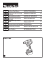
Makita DAS180 Manual de utilizare
- Categorie
- Unelte electrice
- Tip
- Manual de utilizare

DAS180
EN Cordless Dust Blower INSTRUCTION MANUAL 9
PL Akumulatorowa Dmuchawa
do Kurzu INSTRUKCJA OBSŁUGI 23
HU Akkumulátoros porfúvó HASZNÁLATI KÉZIKÖNYV 38
SK Akumulátorové prachové
dúchadlo NÁVOD NA OBSLUHU 52
CS Akumulátorový fukar na
prach NÁVOD K OBSLUZE 66
UK Акумуляторна повітродувка ІНСТРУКЦІЯ З
ЕКСПЛУАТАЦІЇ 80
RO Suantă de praf fără r MANUAL DE INSTRUCŢIUNI 95
DE Akku Gebläse BETRIEBSANLEITUNG 110

2
1
1
2
2
3
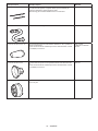
Fig.1
2
1
Fig.2
1
2
Fig.3
1
2
3
4
Fig.4
2
4
31
Fig.5
1
2
3
Fig.6
12
Fig.7

3
12
Fig.8
12
3
4
5
6
Fig.9
2
1
3
4
5
Fig.10
1 1
2
3
Fig.11
1
2
3
4
Fig.12
1
4
5
3
2
Fig.13
1
2
3
4
Fig.14

4
2
4
31
Fig.15
1
2
3
Fig.16
1
2
Fig.17
1
2
1
2
34
Fig.18
1
Fig.19
1
2
Fig.20
1
2
3
4
5
Fig.21

5
2
1
3
Fig.22
1
2
Fig.23
1
2
3
3
1
2
Fig.24
Fig.25
Fig.26
Fig.27
1
2
Fig.28
Fig.29

6
Fig.30
Fig.31
Fig.32
11
2
3
4
5
4
Fig.33
Fig.34
Fig.35
Fig.36
1
Fig.37

7
Fig.38
Fig.39
Fig.40
1
2
3
4
Fig.41
1
Fig.42
1
Fig.43
Fig.44
Fig.45

8
12
Fig.46
2
4
31
Fig.47

9ENGLISH
ENGLISH (Original instructions)
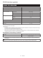
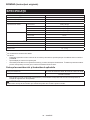
SPECIFICATIONS
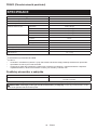
Model: DAS180
Air speed (average) *2 *3 163 m/s
Air speed (max.) *2 *3 200 m/s
Maximum air volume *1 *2 1.1 m3/min
Maximum blowing force *1 *2 4: Max 2.8 N (0.29 kgf)
3: High 2.3 N (0.23 kgf)
2: Medium 1.7 N (0.17 kgf)
1: Low 1.1 N (0.11 kgf)
Continuous use *1 *2 4: Max 15 min
3: High 20 min
2: Medium 30 min
1: Low 55 min
Maximum air pressure *2 *3 29.7 kPa
Dimensions (L x W x H) *1 *2 179 mm x 92 mm x 297 mm
Rated voltage D.C. 18 V
Net weight 1.2 - 1.7 kg
*1 Without nozzles
*2 With battery model BL1860B
*3 With nozzle 7
• Duetoourcontinuingprogramofresearchanddevelopment,thespecicationshereinaresubjecttochange
without notice.
• Specicationsmaydierfromcountrytocountry.
• Theweightmaydierdependingontheattachment(s),includingthebatterycartridge.Thelightestandheavi-
est combinations, according to EPTA-Procedure 01/2014, are shown in the table.
Applicable battery cartridge and charger
Battery cartridge BL1815N / BL1820B / BL1830B / BL1840B / BL1850B / BL1860B
Charger DC18RC / DC18RD / DC18RE / DC18SD / DC18SE / DC18SF /
DC18SH / DC18WC
• Some of the battery cartridges and chargers listed above may not be available depending on your region of
residence.
WARNING: Only use the battery cartridges and chargers listed above. Use of any other battery cartridges
andchargersmaycauseinjuryand/orre.

10 ENGLISH
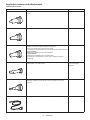
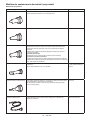
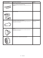
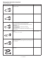
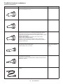
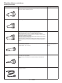
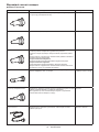
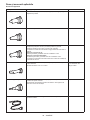
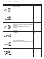
Applicable nozzles and attachments
Optional accessories
Nozzles and attachments Applications and purposes Diameters
Nozzle 3 Blowingairintoconnedspaces,corners,andspacesbythewallsto
dusto.
ø3.0 mm
Nozzle 7 Dustingolters. ø7.0 mm
Nozzle 13 Using as blower
Cleaning work surfaces and blowing dust in general.
Anchor hole cleaning with optional long nozzles.
Functioningasajointbetweenlongnozzlesandbloweroutletofthetool.
Using as inator
Inatinglargeinatablepoolsorairmattresses.
Using as deator
Deatinglargeinatablepoolsorairmattresses.
Functioningasajointbetweenairventhosecompleteandrubber
attachments.
ø13 mm
Wide range nozzle Blowing air over dirt and liquid on desktop and wide-open area.
Blowing range: 120° with 5 holes
ø6.0 mm
* As a single hole
diameter
Pinch valve nozzle Inating/deatingbeachtoys,pillows,andsimilarplasticinatables.
*Deatingoperationcanbecarriedoutwithoptionalairventhose
complete.
ø7.0 mm
Flexible nozzle 6 Blowing dust out of any hard-to-reach spots, PCs and similar devices. ø6.0 mm x 800 mm

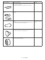
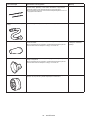
11 ENGLISH
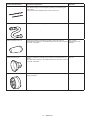
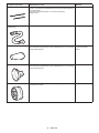
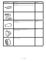
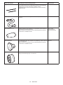
Nozzles and attachments Applications and purposes Diameters
Long nozzles set A set of nozzles suitable for blowing dust out of anchor holes and narrow
spots. Nozzle lengths can be changed by attaching and detaching two
nozzle heads.
*Longnozzlescanbeinstalledusingnozzle13asajoint.
ø8.0 mm
Air vent hose complete Deatinginatableitemswithappropriatenozzlesinoperation. -
Rubber attachment 20 - 30 Nozzleheadsuitablefordeatingairmattress,raft,boat,andpool.
* This attachment requires to be installed with the air vent hose complete
and nozzle 13 together.
ø20 - 30 mm
* Measured as outer
diameter.
Rubber attachment 65 Attachment suitable for packaging your clothes by compressing air out
of them.
* This attachment requires to be installed with the air vent hose complete
and nozzle 13 together.
ø65 mm
Filter C Attachment designed to reduce dust intake into the motor under dusty
working conditions.
-

12 ENGLISH
Symbols
The followings show the symbols which may be used
for the equipment. Be sure that you understand their
meaning before use.
Read instruction manual.
Keep hands away from rotating parts.
Long hair may cause entanglement
accident.
Keep bystanders away.
Wear eye and ear protection.
Do not expose to moisture.
Ni-MH
Li-ion
Only for EU countries
Due to the presence of hazardous com-
ponents in the equipment, waste electrical
and electronic equipment, accumulators
and batteries may have a negative impact
on the environment and human health.
Do not dispose of electrical and electronic
appliances or batteries with household
waste!
In accordance with the European Directive
on waste electrical and electronic equip-
ment and on accumulators and batteries
and waste accumulators and batteries,
as well as their adaptation to national law,
waste electrical equipment, batteries and
accumulators should be stored separately
and delivered to a separate collection point
for municipal waste, operating in accor-
dance with the regulations on environmen-
tal protection.
This is indicated by the symbol of the
crossed-out wheeled bin placed on the
equipment.
Intended use
Thetoolisintendedforblowingdust,inatingand
deatinginatables,withchangeablenozzlesaccording
to your preferences. Suitable for both commercial and
homeuse,e.g.,cleaningworkspaces,dustinglters,
andinatingbeachtoys.
Noise
The typical A-weighted noise level determined accord-
ing to EN62841-1:
Sound pressure level (LpA) : 79 dB(A)
Uncertainty (K) : 3 dB(A)
The noise level under working may exceed 80 dB (A).
NOTE: The declared noise emission value(s) has
been measured in accordance with a standard test
method and may be used for comparing one tool with
another.
NOTE: The declared noise emission value(s)
may also be used in a preliminary assessment of
exposure.
WARNING: Wear ear protection.
WARNING:
The noise emission during actual
use of the power tool can dier from the declared
value(s) depending on the ways in which the tool is
used especially what kind of workpiece is processed.
WARNING:
Be sure to identify safety measures
to protect the operator that are based on an estima-
tion of exposure in the actual conditions of use (tak-
ing account of all parts of the operating cycle such
as the times when the tool is switched o and when
it is running idle in addition to the trigger time).
Vibration
The vibration total value (tri-axial vector sum) deter-
mined according to EN62841-1:
Work mode: operation without load
Vibration emission (ah) : 2.5 m/s2 or less
Uncertainty (K) : 1.5 m/s2
NOTE: The declared vibration total value(s) has been
measured in accordance with a standard test method
and may be used for comparing one tool with another.
NOTE: The declared vibration total value(s) may also
be used in a preliminary assessment of exposure.
WARNING: The vibration emission during
actual use of the power tool can dier from the
declared value(s) depending on the ways in which
the tool is used especially what kind of workpiece
is processed.
WARNING: Be sure to identify safety mea-
sures to protect the operator that are based on an
estimation of exposure in the actual conditions of
use (taking account of all parts of the operating
cycle such as the times when the tool is switched
o and when it is running idle in addition to the
trigger time).
Declarations of Conformity
For European countries only
The Declarations of conformity are included in Annex A
to this instruction manual.
SAFETY WARNINGS
General power tool safety warnings
WARNING Read all safety warnings, instruc-
tions, illustrations and specications provided with
this power tool. Failure to follow all instructions listed
belowmayresultinelectricshock,reand/orserious
injury.
Save all warnings and instruc-
tions for future reference.
The term "power tool" in the warnings refers to your
mains-operated (corded) power tool or battery-operated
(cordless) power tool.

13 ENGLISH
Cordless Dust Blower Safety
Instructions
Training
1. Read the instructions carefully. Be familiar
with the controls and the correct use of the
dust blower.
2. Never allow children, persons with reduced
physical, sensory or mental capabilities or
lack of experience and knowledge or people
unfamiliar with these instructions to use the
dust blower. Local regulations may restrict the
age of the operator.
3. Never operate the dust blower while people,
especially children, or pets are nearby.
4. Keep in mind that the operator or user is
responsible for accidents or hazards occurring
to other people or their property.
Preparation
1. Do not wear loose clothing or jewellery that
can be drawn into the air inlet. Keep long hair
away from the air inlets.
2. To prevent dust irritation the wearing of a face
mask is recommended.
3. Use personal protective equipment. Always
wear eye protection. Protective equipment such
as a dust mask, non-skid safety shoes, hard hat or
hearing protection used for appropriate conditions
willreducepersonalinjuries.
Operation in general
1. Switch o the dust blower and remove the bat-
tery cartridge and make sure that all moving
parts have come to a complete stop
• whenever you leave the dust blower.
• whenever you switch from inating to
deating operation, and vice versa.
• before checking, cleaning or working on
the dust blower.
• if the dust blower starts to vibrate
abnormally.
2. Operate the dust blower only in daylight or in
good articial light.
3. Do not overreach and keep proper balance and
footing at all times.
4. Keep all cooling air inlets clear of debris.
5. Operate the dust blower in a recommended
position and on a rm surface.
6. Do not use the tool with wet hands.
7. Do not point the outlet of the nozzle and
attachment to yourself or others.Objectsmay
beblownawayandcauseaninjury.
8. Do not use the tool to spray chemicals. Your
lungs may be damaged by inhaling toxic fumes.
9. Do not operate the dust blower at high places.
10. Never block suction inlet and/or blower outlet.
• Be careful not to block suction inlet or
blower outlet with dust or dirt when oper-
ating in dusty area.
• Do not use nozzles other than the nozzles
provided by Makita.
11. If the dust blower strikes any foreign objects
or should start making any unusual noise
or vibration, immediately switch o the dust
blower to stop it. Remove the battery car-
tridge from the dust blower and inspect the
dust blower for damage before restarting and
operating the dust blower. If the dust blower
is damaged, ask Makita Authorized Service
Centers for repair.
12. Do not insert ngers or other objects into
suction inlet or blower outlet.
13. Prevent unintentional starting. Ensure the
switch is in the o-position before inserting
battery cartridge, picking up or carrying the
dust blower. Carrying the dust blower with
your nger on the switch or energizing the
dust blower that has the switch on invites
accidents.
14. Avoid operating the dust blower for a long time
in low temperature environment.
15. Do not use the tool beyond the maximum out-
put pressure of the tool. Using the tool at output
pressure greater than the maximum output pres-
sureofthetoolmaybursttheobjectorthetool.
Blowing operation
1. Never blow debris in the direction of
bystanders.
2. Never point the nozzle at anyone in the vicinity
when using the dust blower.
3. Never blow dangerous materials, such as
nails, fragments of glass, or blades.
4. Do not operate the dust blower near ammable
materials.
Inating/Deating operation
1. When inating objects, connect a nozzle or
attachment to the air inlet securely. Otherwise,
theobject,nozzle,orattachmentmaybedam-
agedandyoumaybeinjured.
2.
Release air pressure slowly. When removing a
nozzle or attachment after inating objects, hold
the object, nozzle and attachment rmly. They
maybounceduetoexhaustairandcauseaninjury.
3. Do not inate object beyond the maximum
pressure of the object. Otherwise, the tool or
objectmaybedamagedandyoumaybeinjured.
4. Inate the objects intended to be inated by
the manufacturer only, such as beach toys or
air mattress.Inatingotherobjectsmaydamage
themandcauseaninjury.
5. When inating objects, check the status of the
tool and object, and be sure that there is no air
leak from the object.
6. Always be careful not to over-inate objects
during operation. It otherwise may burst the
objects,possiblycausingdamagetothetooland
personalinjury.
7. After inating objects, check the air pressure
using a reliable and calibrated measuring
equipment.
8. Never leave the tool unattended when the
nozzle or attachment is attached to the object
or during operation.
9. Do not use the tool as a vacuum cleaner.
Performing dust collection may damage the tool.

14 ENGLISH
10. Do not use the tool as a breathing device.
11.
Use only standard accessories provided by
Makita. The use of any other accessories or attach-
mentsmightpresentariskofinjurytopersons.
Maintenance and storage
1. Keep all nuts, bolts and screws tight to be sure
the dust blower is in safe working condition.
2. If the parts are worn or damaged, replace them
with parts provided by Makita.
3. Store the dust blower in a dry place out of the
reach of children.
4. When you stop the dust blower for inspection,
servicing, storage, or changing accessory,
switch o the dust blower and make sure that
all moving parts come to a complete stop, and
remove the battery cartridge. Cool down the
dust blower before making any work on the
dust blower. Maintain the dust blower with
care and keep it clean.
5. When carrying the tool, do not hold or pull a
nozzle or attachment. The tool may be damaged
andcauseaninjury.
6.
Always cool down the dust blower before storing.
7. Do not expose the dust blower to rain. Store
the dust blower indoors.
8. Do not disassemble the tool.
Service
1. Have your power tool serviced by a qualied
repair person using only identical replacement
parts. This will ensure that the safety of the power
tool is maintained.
2. Never service damaged battery packs. Service
of battery packs should only be performed by the
manufacturer or authorized service providers.
SAVE THESE INSTRUCTIONS.
WARNING: DO NOT let comfort or familiarity
with product (gained from repeated use) replace
strict adherence to safety rules for the subject
product.
MISUSE or failure to follow the safety rules stated
in this instruction manual may cause serious
personal injury.
Important safety instructions for
battery cartridge
1. Before using battery cartridge, read all instruc-
tions and cautionary markings on (1) battery
charger, (2) battery, and (3) product using
battery.
2. Do not disassemble or tamper with the battery
cartridge.Itmayresultinare,excessiveheat,
or explosion.
3. If operating time has become excessively
shorter, stop operating immediately. It may
result in a risk of overheating, possible burns
and even an explosion.
4. If electrolyte gets into your eyes, rinse them
out with clear water and seek medical atten-
tion right away. It may result in loss of your
eyesight.
5. Do not short the battery cartridge:
(1) Do not touch the terminals with any con-
ductive material.
(2) Avoid storing battery cartridge in a con-
tainer with other metal objects such as
nails, coins, etc.
(3) Do not expose battery cartridge to water
or rain.
A battery short can cause a large current
ow, overheating, possible burns and even a
breakdown.
6. Do not store and use the tool and battery car-
tridge in locations where the temperature may
reach or exceed 50 °C (122 °F).
7. Do not incinerate the battery cartridge even if
it is severely damaged or is completely worn
out. The battery cartridge can explode in a re.
8. Do not nail, cut, crush, throw, drop the battery
cartridge, or hit against a hard object to the
battery cartridge. Such conduct may result in a
re,excessiveheat,orexplosion.
9. Do not use a damaged battery.
10. The contained lithium-ion batteries are subject
to the Dangerous Goods Legislation require-
ments.
For commercial transports e.g. by third parties,
forwarding agents, special requirement on pack-
aging and labeling must be observed.
For preparation of the item being shipped, consult-
ing an expert for hazardous material is required.
Please also observe possibly more detailed
national regulations.
Tapeormaskoopencontactsandpackupthe
battery in such a manner that it cannot move
around in the packaging.
11. When disposing the battery cartridge, remove
it from the tool and dispose of it in a safe
place. Follow your local regulations relating to
disposal of battery.
12. Use the batteries only with the products
specied by Makita. Installing the batteries to
non-compliantproductsmayresultinare,exces-
sive heat, explosion, or leak of electrolyte.
13. If the tool is not used for a long period of time,
the battery must be removed from the tool.
14. During and after use, the battery cartridge may
take on heat which can cause burns or low
temperature burns. Pay attention to the han-
dling of hot battery cartridges.
15. Do not touch the terminal of the tool imme-
diately after use as it may get hot enough to
cause burns.
16. Do not allow chips, dust, or soil stuck into the
terminals, holes, and grooves of the battery
cartridge.Itmaycauseheating,catchingre,
burst and malfunction of the tool or battery car-
tridge,resultinginburnsorpersonalinjury.
17. Unless the tool supports the use near
high-voltage electrical power lines, do not use
the battery cartridge near high-voltage electri-
cal power lines. It may result in a malfunction or
breakdown of the tool or battery cartridge.
18. Keep the battery away from children.
SAVE THESE INSTRUCTIONS.

15 ENGLISH
CAUTION: Only use genuine Makita batteries.
Use of non-genuine Makita batteries, or batteries that
have been altered, may result in the battery bursting
causingres,personalinjuryanddamage.Itwill
also void the Makita warranty for the Makita tool and
charger.
Tips for maintaining maximum
battery life
1. Charge the battery cartridge before completely
discharged. Always stop tool operation and
charge the battery cartridge when you notice
less tool power.
2. Never recharge a fully charged battery car-
tridge. Overcharging shortens the battery
service life.
3. Charge the battery cartridge with room tem-
perature at 10 °C - 40 °C (50 °F - 104 °F). Let
a hot battery cartridge cool down before
charging it.
4. When not using the battery cartridge, remove
it from the tool or the charger.
5. Charge the battery cartridge if you do not use
it for a long period (more than six months).
ASSEMBLY
CAUTION: Always be sure that the tool is
switched o and the battery cartridge is removed
before carrying out any work on the tool.
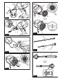
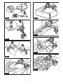
Installing nozzle
Aligntheguideprojectionsonanozzlewiththelocking
notches on the lock sleeve of the tool, then push the
nozzlermlyintothelocksleeveuntilitlocksinplace
with a click. Having installed the nozzle, try pulling it
back to ensure it is securely held in place.
►Fig.1: 1.Guideprojections2. Locking notches
3. Lock sleeve
NOTICE: Make sure that the nozzle has been
correctly attached to the tool so the guide pro-
jections on the nozzle neatly t into the locking
notches on the lock sleeve.
Removing nozzle
Hold the nozzle end and rotate it in a direction indicated
by the arrows on the nozzle end to release the lock. Pull
the nozzle apart from the lock sleeve after it becomes
unlocked.
►Fig.2: 1. Nozzle end 2. Lock sleeve
NOTICE: Adhered dirt and dust on the surface
will possibly make it hard to remove the nozzle
from the tool. In such a case, slide and hold the
lock sleeve towards the motor housing rst, and
then turn the nozzle end to release the lock.
CAUTION: Be careful not to pinch your hands
between the rear end of the lock sleeve and motor
housing while removing the nozzle. The lock
sleeve slides back towards the motor housing when
the nozzle is released from the lock.
►Fig.3: 1. Lock sleeve 2. Motor housing
Removing and installing dust cap
1. Turn the dust cap on the suction inlet at the rear of
the housing counterclockwise to take the dust cap out
of the housing. Two locking tabs on the dust cap can be
disengaged by aligning them with the guide grooves on
the housing.
►Fig.4: 1. Dust cap 2. Locking tabs 3. Suction inlet
4. Guide grooves
2. Reassemble the dust cap onto the suction inlet,
aligning the two locking tabs on the dust cap with the
guide grooves on the housing. Then turn the dust cap
clockwise to secure it in place.
►Fig.5: 1. Dust cap 2. Locking tabs 3. Suction inlet
4. Guide grooves
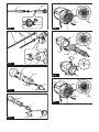
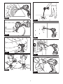
Installing and removing long
nozzles
Optional accessory
A set of long nozzles helps clean dust out of small holes
and narrow spots. Nozzle lengths can be arranged
according to your requirements.
►Fig.6: 1. Nozzle 13 2. Long nozzle R 3. Long noz-
zle F
1. Insert the long nozzle R through the air hole of the
nozzle 13 from back to front. Pass it though until the
nozzle 13 secures in place at the rear end of the long
nozzle R.
►Fig.7: 1. Nozzle 13 2. Long nozzle R
2. Place the long nozzle F over the front end of the
long nozzle R. Hand screw the long nozzle F until it is
tightened securely.
►Fig.8: 1. Long nozzle F 2. Long nozzle R
3. Aligntheguideprojectionsonthenozzle13with
the locking notches on the lock sleeve of the tool, then
pushthenozzle13rmlyintothelocksleeveuntilit
locks in place with a click.
►Fig.9: 1.Guideprojection2. Locking notch 3. Lock
sleeve 4. Nozzle 13 5. Long nozzle R 6. Long
nozzle F
NOTE: Use the long nozzle R only to have a shorter
operating range. Use both the long nozzle R and F to
allow a wider operating range.
4. To remove the long nozzles, detach the nozzle 13
from the lock sleeve of the tool, and then disassemble
the long nozzles.

16 ENGLISH
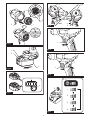
Installing and removing deating
nozzles and attachments
Optional accessory
NOTICE: Always be sure to install and uninstall
deating nozzles and attachments only while the
air vent hose complete is disconnected from the
tool. Handling the air vent hose complete assembled
into the tool may cause the tool to stand unstable
resulting in it falling over.
1. Aligntheguideprojectionsonthepinchvalve
nozzle with the locking notches on the lock sleeve of the
air vent hose complete, then push the pinch valve noz-
zlermlyintothelocksleeveuntilitlocksinplacewitha
click.
►Fig.10: 1. Pinch valve nozzle 2.Guideprojections
3. Locking notches 4. Lock sleeve 5. Air
vent hose complete
Optional rubber attachments
Optional rubber attachments require to be placed over
the nozzle. Be careful not to attach rubber attachments
directly to the air vent hose complete.
i Aligntheguideprojectionsonthenozzle13with
the locking notches on the lock sleeve of the air vent
hosecomplete,thenpushthenozzlermlyintothelock
sleeve until it locks in place with a click.
ii Place a rubber attachment over the nozzle head
by pushing and hand screwing it in place.
►Fig.11: 1. Rubber attachments 2. Nozzle 13 3. Air
vent hose complete
NOTICE: Make sure that the nozzle has been
correctly attached to the air vent hose complete
so the guide projections on the nozzle neatly t
into the locking notches on the lock sleeve.
2. Turn the dust cap on the suction inlet at the rear of
the housing counterclockwise to take the dust cap out
of the housing. Two locking tabs on the dust cap can be
disengaged by aligning them with the guide grooves on
the housing.
►Fig.12: 1. Dust cap 2. Locking tabs 3. Suction inlet
4. Guide grooves
3. Attach the end of the air vent hose complete to
the suction inlet, aligning the two locking tabs on the
air vent hose complete with the guide grooves on the
housing.Thenholdandturntherearcusoftheairvent
hose complete clockwise to secure it in place.
►Fig.13: 1. Air vent hose complete 2.Rearcus
3. Suction inlet 4. Locking tabs 5. Guide
grooves
4. Toremovethedeatingnozzleandattachments,
follow the installation steps in reverse.
NOTICE: Always hold and turn the rear cus of
the air vent hose complete to install and uninstall
the air vent hose complete in place.
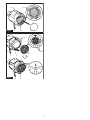
Installing optional lter
Optional accessory
Anoptionalhighperformancelter(FilterC)isavailable
for restricting dust intake into the motor under dusty
working conditions.
1.
Turn the dust cap on the suction inlet at the rear of
the housing counterclockwise to take the dust cap out of the
housing. Two locking tabs on the dust cap can be disengaged
by aligning them with the guide grooves on the housing.
►Fig.14: 1. Dust cap 2. Locking tabs 3. Suction inlet
4. Guide grooves
2.
Replaceanoptionalhighperformancelteronthe
suction inlet, aligning the two locking tabs on the optional
lterwiththeguidegroovesonthehousing.Thenturnthe
optionallterclockwisetosecureitinplace.
►Fig.15:
1.Optionalhighperformancelter2. Locking
tabs 3. Suction inlet 4. Guide grooves
NOTICE: An optional high performance lter
(Filter C) can be reused many times by cleaning it
out. Clean dust o the lter regularly as a clogged
lter may block the airow and cause less e-
cient operation. Occasionally wash the lter in
water, rinse and dry thoroughly in the shade
before use.
NOTICE: Do not wipe, rub or scratch an optional
high performance lter (Filter C) hardly. Be sure
to shake or blow dust o the lter with care.
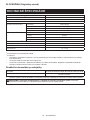
FUNCTIONAL
DESCRIPTION
CAUTION: Always be sure that the tool is
switched o and the battery cartridge is removed
before adjusting or checking function on the tool.
Installing or removing battery
cartridge
CAUTION: Always switch o the tool before
installing or removing of the battery cartridge.
CAUTION: Hold the tool and the battery car-
tridge rmly when installing or removing battery
cartridge. Failure to hold the tool and the battery
cartridgermlymaycausethemtoslipoyourhands
and result in damage to the tool and battery cartridge
andapersonalinjury.
►Fig.16: 1. Red indicator 2. Button 3. Battery
cartridge
To remove the battery cartridge, slide it from the tool
while sliding the button on the front of the cartridge.
To install the battery cartridge, align the tongue on the
battery cartridge with the groove in the housing and slip
it into place. Insert it all the way until it locks in place
with a little click. If you can see the red indicator as
showninthegure,itisnotlockedcompletely.

17 ENGLISH
CAUTION: Always install the battery cartridge
fully until the red indicator cannot be seen. If not,
itmayaccidentallyfalloutofthetool,causinginjuryto
you or someone around you.
CAUTION: Do not install the battery cartridge
forcibly. If the cartridge does not slide in easily, it is
not being inserted correctly.
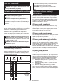
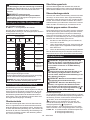
Indicating the remaining battery
capacity
Only for battery cartridges with the indicator
►Fig.17: 1. Indicator lamps 2. Check button
Press the check button on the battery cartridge to indi-
cate the remaining battery capacity. The indicator lamps
light up for a few seconds.
Indicator lamps Remaining
capacity
Lighted O Blinking
75% to 100%
50% to 75%
25% to 50%
0% to 25%
Charge the
battery.
The battery
may have
malfunctioned.
NOTE: Depending on the conditions of use and the
ambienttemperature,theindicationmaydierslightly
from the actual capacity.
NOTE:Therst(farleft)indicatorlampwillblinkwhen
the battery protection system works.
Tool / battery protection system
The tool is equipped with a tool/battery protection sys-
tem.Thissystemautomaticallycutsopowertothe
motor to extend tool and battery life. The tool will auto-
matically stop during operation if the tool or battery is
placed under one of the following conditions:
Overload protection
When the tool/battery is operated in a manner that
causes it to draw an abnormally high current, the tool
stopsautomatically.Inthissituation,turnthetoolo
and stop the application that caused the tool to become
overloaded. Then turn the tool on to restart.
Overheat protection
When the tool/battery is overheated, the tool stops
automatically. In this situation, let the tool cool down
before turning the tool on again.
Overdischarge protection
When the battery becomes low on power during use,
the lamp will blink to alert you. Then the tool automati-
cally stops, with the lamp remaining lit for approximately
10 seconds, shortly after the battery power becomes
too low to operate during continuing use. In such cases,
remove the battery from the tool and charge the battery.
Protections against other causes
Protection system is also designed for other causes that could
damage the tool and allows the tool to stop automatically.
Take all the following steps to clear the causes, when the tool
has been brought to a temporary halt or stop in operation.
1.
Turnthetoolo,andthenturnitonagaintorestart.
2. Charge the battery(ies) or replace it/them with
recharged battery(ies).
3. Let the tool and battery(ies) cool down.
If no improvement can be found by restoring protection
system, then contact your local Makita Service Center.
Switch action
CAUTION: Before installing the battery car-
tridge into the tool, always check to see that the
switch trigger actuates properly and returns to
the "OFF" position when released.
CAUTION: Switch can be locked in "ON"
position for ease of operator comfort during
extended use. Apply caution while locking tool in
"ON" position.
CAUTION: Do not install the battery cartridge
with the lock-on button engaged.
CAUTION: When not operating the tool,
depress the trigger-lock button from the side on
which a locking mark ( ) is indicated to lock the
switch trigger in the "OFF" position.
Trigger-lock button
To prevent the switch trigger from being accidentally pulled, the
trigger-lock button is provided. To start the tool, depress the trig-
ger-lock button from the side on which an unlocking mark ( ) is
indicated. To lock the tool, depress the trigger-lock button from
the side on which a locking mark ( ) is indicated.
Make sure to set the trigger-lock button back in a lock-
ing position after each use.
►Fig.18: 1. Switch trigger 2. Trigger-lock button
3. Unlocking mark 4. Locking mark
NOTICE: Do not pull the switch trigger hard
without releasing the trigger-lock button. This can
cause switch breakage.
Switch trigger
Air volume can be controlled by squeezing the switch
trigger. Air volume is grown by increasing pressure on
the switch trigger. Release the switch trigger to stop.
►Fig.19: 1. Switch trigger
Lock button
For continuous operation, push in the lock button while pulling the
switch trigger and then release the switch trigger. To cancel the
locked-on operation, pull the switch trigger fully, then release it.
►Fig.20: 1. Switch trigger 2. Lock button

18 ENGLISH
Adjusting air volume
Air volume can be changed in four modes, that is, 4 (Max), 3 (High),
2 (Medium) and 1 (Low), depending on the application and workload.
Presstheairvolumeadjustmentbuttontoswitchmode
in the following sequence. The mode changes every
time you press the button.
►Fig.21: 1. Low air volume 2. Medium air volume
3. High air volume 4. Max air volume 5. Air
volumeadjustmentbutton
Air volume settings table
Air volume mode Maximum air volume
4: Max 1.1 m3/min
3: High 1.0 m3/min
2: Medium 0.8 m3/min
1: Low 0.6 m3/min
* Maximum air volumes are measured without
nozzles.
NOTE: Air volume mode can be changed before
turning the tool on.
NOTE: The tool restarts operation in the air volume
mode that was last used.
Lighting up the lamp
CAUTION: Do not look in the light or see the
source of light directly.
To turn the lamp on, perform one of the following steps.
•
Presstheairvolumeadjustmentbuttontolightthelamp
up. The lamp remains lit for approximately 10 seconds.
• Pull the switch trigger to light the lamp up. The
lamp keeps on lighting while the switch trigger is
being pulled. The lamp goes out approximately 10
seconds after stopping operation.
NOTE: When the remaining battery capacity gets low,
the lamp starts blinking. The timing, at which the lamp
starts blinking depends on the temperature at work
place and the battery cartridge conditions.
►Fig.22: 1.Airvolumeadjustmentbutton2. Switch
trigger 3. Lamp
Hanging hole
CAUTION: Before hanging the tool, always
make sure that the hanging hole is not damaged.
CAUTION:
Use the hanging/mounting parts for
their intended purposes only. Using for unintended
purposemaycauseaccidentorpersonalinjury.
CAUTION: Withstanding load rated for your
tools racks and holders needs to be learned
beforehand. Do not place the tool if it exceeds the
withstanding load on the racks and holders.
CAUTION: Be sure that the hanging hole is
securely hooked before releasing your hold.
Use the hanging hole at the top rear of the housing to
hang the tool on a hook of racks and holders.
►Fig.23: 1. Hanging hole 2. Hook
Installing hook
Optional accessory
WARNING: Use the hanging/mounting parts
for their intended purposes only, e.g., hanging the
tool on a tool belt between jobs or work intervals.
WARNING: Be careful not to overload the
hook as too much force or irregular overburden
may cause damages to the tool resulting in per-
sonal injury.
CAUTION: When installing the hook, always
secure it with the screw rmly. If not, the hook
maycomeofromthetoolandresultinthepersonal
injury.
CAUTION: Make sure to hang the tool
securely before releasing your hold.Insucient
orunbalancedhookingmaycausefallingoandyou
maybeinjured.
►Fig.24: 1. Groove 2. Hook 3. Screw
The hook is convenient for temporarily hanging the tool.
This can be installed on either side of the tool. To install
the hook, insert it into a groove in the tool housing on
either side and then secure it with a screw. To remove,
loosen the screw and then take it out.
OPERATION
CAUTION: Do not point the nozzle at anyone
nearby during operation.
NOTICE: Do not block suction inlet and/or
blower outlet during operation.
Blowing in general use
Recommended nozzles
— Nozzle 13
Cleanyourworksurfacesandoorsbyblowingodust,
dirt, debris, scrap or waste in general.
Direct the nozzle towards surfaces at an appropriate
distanceandswingitaroundtoblowoentirely.
►Fig.25
CAUTION: Never blow debris in the direction
of bystanders or pets.
CAUTION: Use personal protective equip-
ment such as a dust mask and eye protection.
NOTICE: Remove blockages on surfaces away
before blowing operation.

19 ENGLISH
Blowing in conned spaces
Recommended nozzles
— Nozzle 3
Blowintoconnedspots,corners,andspacesbythe
wallstodusto.
Point the nozzle straight at spaces at a reasonable
distance and squeeze the switch trigger to control blow-
ing air volume.
►Fig.26
►Fig.27
CAUTION: Keep the nozzle away a reasonable
distance from blowing spots to avoid blowing up
dust into the air.
CAUTION: Use personal protective equip-
ment such as a dust mask and eye protection.
NOTICE: Avoid blocking the air vent holes
around the blower outlet. It otherwise may cause
suddennoiseandvibrationsandcouldpossiblyaect
the tool performance.
►Fig.28: 1. Air vent holes 2. Blower outlet
Dusting air lter
Recommended nozzles
— Nozzle 7
Dustltersurfacesbyblowingairthroughonesideof
theltertotheother.
Directthenozzleonltersurfaceswithinashortdis-
tance and swing it from side to side to blow dust away
from surfaces.
►Fig.29
CAUTION: Use personal protective equip-
ment such as a dust mask and eye protection.
NOTE: Point the nozzle at an angle according to the
outlinesoftheltersotheadhereddustcanbeeasily
removed.
Blowing wide and open area
Recommended nozzles
— Wide range nozzle
Blow air over dirt and liquid on wide-open surfaces such
asdesktopandoor,usingtheve-holenozzlewith120
degree range of blowing.
Direct the nozzle over a large area within a certain
distance and swing it back and forth and from side to
side to blow widely.
►Fig.30
CAUTION: Use personal protective equip-
ment such as a dust mask and eye protection.
Inating plastic inatables
Recommended nozzles
— Pinch valve nozzle
— Nozzle 13
Inatable air volume with fully charged battery
cartridge BL1860B without recharging it
Air volume mode
Inatable air
volume
(With pinch valve
nozzle)
Number of ø61 cm
plastic beach balls
equivalent in air
volume
(With pinch valve
nozzle)
4: Max 13.0 m3110
3: High 13.4 m3115
2: Medium 15.6 m3130
1: Low 22.8 m3190
NOTE:
The maximum output air pressure of this tool is 20.2 kPa.
(With nozzle 13)
Inatebeachtoys,pillows,andsimilarsmallplastic
inatableswithpinchvalvenozzle.
Inategardenpools,airmattresses,andsimilarlarge
plasticinatableswithnozzle13.
Insertthenozzleintoanairinletonaninatableitem
andpulltheswitchtriggertostartinating.
Slowlyreleasetheswitchtriggertoreduceairvolumeastheinat-
ableitemcomesclosetofullyinated.Removethenozzlefrom
theairinletafterstoppingtheairowandthenclosetheairinlet.
►Fig.31
►Fig.32
CAUTION: Always be careful not to over-in-
ate inatables during operation. It otherwise may
bursttheinatables,possiblycausingdamagetothe
toolandpersonalinjury.
CAUTION: Never leave the tool unattended
while the nozzle is attached to inatables or
during operation.
CAUTION: Be aware that heated air stream
may ow through the air vent hole at bottleneck
of the pinch valve nozzle due to air circulation.
NOTE: Make sure to insert the pinch valve nozzle
fully through the air inlet so the nozzle head serves to
opentheapvalveinsidetheairinlet.
NOTE:Foraninatableitemwithasmallairinlet
opening, insert the narrow tip of the pinch valve noz-
zle in the air inlet until the bottleneck of the nozzle
head touches the rim of the air inlet.
NOTE:Foraninatableitemwithalargeairinlet
opening, insert the pinch valve nozzle head fully into
theairinlettoopentheapvalveinsidetheairinlet.
►Fig.33:
1. Flap valve 2. Small air inlet opening 3. Large
air inlet opening 4. Bottleneck 5. Air vent hole
NOTE:Ifanairinletonaninatableitemisrelatively
smaller than the pinch valve nozzle head, squeeze
and enlarge the air inlet by hand and then twist and
hold the nozzle head into the air inlet.

20 ENGLISH
Blowing in holes and narrow spots
Optional accessory
Recommended nozzles
— Long nozzles set
Clean dust out of small holes and narrow spots.
Nozzle lengths can be arranged according to your
requirements.
Assemble the long nozzle R and F together to allow a
longer operating range, for instance, cleaning anchor
holes at your feet.
►Fig.34
Use the long nozzle R only to have a shorter operating
range, for instance, cleaning spots on the wall.
►Fig.35
CAUTION: Use personal protective equip-
ment such as a dust mask and eye protection.
Blowing in narrow spaces
Optional accessory
Recommended nozzles
— Flexible nozzle 6
Blowdustoutofanyhard-to-reachspots.Highlyeec-
tive for engine cleaning, in-car dust removal, computer
case dust blowing.
Point the nozzle at an angle within touching distance,
and blow back and forth to clean out lingering dust.
Changeanglesofthenozzleasyoublowotohelp
blow out some of the tougher pieces of debris and dust.
►Fig.36
CAUTION: Use personal protective equip-
ment such as a dust mask and eye protection.
NOTICE: Avoid blocking the air vent holes
around the exible hose end. It otherwise may
cause sudden noise and vibrations and could possi-
blyaectthetoolperformance.
►Fig.37: 1. Air vent holes
Deating plastic inatables
Optional accessory
NOTICE: An exhaust air stream ows through
the blower outlet of the tool. Do not vent exhaust
air into a wall, ceiling, or concealed space of
building.
NOTICE: Avoid deating inatable items in wet
and dusty conditions since water, dust, and sim-
ilar external substances on surfaces may reach
into the motor causing damages to the tool. Dry
and clean inatables o thoroughly before per-
forming deating operation.
NOTICE: Never leave the tool unattended while
deating inatables. Running the motor contin-
uously after deation is completed may cause
overheating.
Recommended nozzles and attachments
— Air vent hose complete
— Pinch valve nozzle
— Rubber attachment 20 - 30
— Rubber attachment 65
Deateinatableitemswithpropernozzlesaccordingto
your preferences and applications.
1. Place a nozzle or rubber attachment onto the air
vent hose complete.
2. Replace the dust cap on the suction inlet of the
tool with the air vent hose complete.
3. Insert the nozzle into the air valve or place the
attachmentovertheairvalveoninatableitems,and
pulltheswitchtriggertostartdeating.
4. Slowly release the switch trigger to reduce suc-
tionvolumeasaninatableitemcomesclosetofully
deated.
5. Remove the nozzle or attachment from the air
valveafterstoppingtheairowandthenclosetheair
valve.
With pinch valve nozzle
►Fig.38
With rubber attachment 20 - 30
►Fig.39
With rubber attachment 65
►Fig.40
MAINTENANCE
CAUTION: Always be sure that the tool is
switched o and the battery cartridge is removed
before attempting to perform inspection or
maintenance.
To maintain product SAFETY and RELIABILITY,
repairs,anyothermaintenanceoradjustmentshould
be performed by Makita Authorized or Factory Service
Centers, always using Makita replacement parts.
NOTICE: Never use gasoline, benzine, thinner,
alcohol or the like. Discoloration, deformation or
cracks may result.
Cleaning
Cleaning body
Clean the body of your tool with a dry cloth or cloth
dampened in soapy water at regular intervals.
Cleaning nozzles
Clear clogs or dust that block the openings of nozzles
before and after each use.
Pagina se încarcă...
Pagina se încarcă...
Pagina se încarcă...
Pagina se încarcă...
Pagina se încarcă...
Pagina se încarcă...
Pagina se încarcă...
Pagina se încarcă...
Pagina se încarcă...
Pagina se încarcă...
Pagina se încarcă...
Pagina se încarcă...
Pagina se încarcă...
Pagina se încarcă...
Pagina se încarcă...
Pagina se încarcă...
Pagina se încarcă...
Pagina se încarcă...
Pagina se încarcă...
Pagina se încarcă...
Pagina se încarcă...
Pagina se încarcă...
Pagina se încarcă...
Pagina se încarcă...
Pagina se încarcă...
Pagina se încarcă...
Pagina se încarcă...
Pagina se încarcă...
Pagina se încarcă...
Pagina se încarcă...
Pagina se încarcă...
Pagina se încarcă...
Pagina se încarcă...
Pagina se încarcă...
Pagina se încarcă...
Pagina se încarcă...
Pagina se încarcă...
Pagina se încarcă...
Pagina se încarcă...
Pagina se încarcă...
Pagina se încarcă...
Pagina se încarcă...
Pagina se încarcă...
Pagina se încarcă...
Pagina se încarcă...
Pagina se încarcă...
Pagina se încarcă...
Pagina se încarcă...
Pagina se încarcă...
Pagina se încarcă...
Pagina se încarcă...
Pagina se încarcă...
Pagina se încarcă...
Pagina se încarcă...
Pagina se încarcă...
Pagina se încarcă...
Pagina se încarcă...
Pagina se încarcă...
Pagina se încarcă...
Pagina se încarcă...
Pagina se încarcă...
Pagina se încarcă...
Pagina se încarcă...
Pagina se încarcă...
Pagina se încarcă...
Pagina se încarcă...
Pagina se încarcă...
Pagina se încarcă...
Pagina se încarcă...
Pagina se încarcă...
Pagina se încarcă...
Pagina se încarcă...
Pagina se încarcă...
Pagina se încarcă...
Pagina se încarcă...
Pagina se încarcă...
Pagina se încarcă...
Pagina se încarcă...
Pagina se încarcă...
Pagina se încarcă...
Pagina se încarcă...
Pagina se încarcă...
Pagina se încarcă...
Pagina se încarcă...
Pagina se încarcă...
Pagina se încarcă...
Pagina se încarcă...
Pagina se încarcă...
Pagina se încarcă...
Pagina se încarcă...
Pagina se încarcă...
Pagina se încarcă...
Pagina se încarcă...
Pagina se încarcă...
Pagina se încarcă...
Pagina se încarcă...
Pagina se încarcă...
Pagina se încarcă...
Pagina se încarcă...
Pagina se încarcă...
Pagina se încarcă...
Pagina se încarcă...
Pagina se încarcă...
Pagina se încarcă...
Pagina se încarcă...
Pagina se încarcă...
Pagina se încarcă...
Pagina se încarcă...
-
 1
1
-
 2
2
-
 3
3
-
 4
4
-
 5
5
-
 6
6
-
 7
7
-
 8
8
-
 9
9
-
 10
10
-
 11
11
-
 12
12
-
 13
13
-
 14
14
-
 15
15
-
 16
16
-
 17
17
-
 18
18
-
 19
19
-
 20
20
-
 21
21
-
 22
22
-
 23
23
-
 24
24
-
 25
25
-
 26
26
-
 27
27
-
 28
28
-
 29
29
-
 30
30
-
 31
31
-
 32
32
-
 33
33
-
 34
34
-
 35
35
-
 36
36
-
 37
37
-
 38
38
-
 39
39
-
 40
40
-
 41
41
-
 42
42
-
 43
43
-
 44
44
-
 45
45
-
 46
46
-
 47
47
-
 48
48
-
 49
49
-
 50
50
-
 51
51
-
 52
52
-
 53
53
-
 54
54
-
 55
55
-
 56
56
-
 57
57
-
 58
58
-
 59
59
-
 60
60
-
 61
61
-
 62
62
-
 63
63
-
 64
64
-
 65
65
-
 66
66
-
 67
67
-
 68
68
-
 69
69
-
 70
70
-
 71
71
-
 72
72
-
 73
73
-
 74
74
-
 75
75
-
 76
76
-
 77
77
-
 78
78
-
 79
79
-
 80
80
-
 81
81
-
 82
82
-
 83
83
-
 84
84
-
 85
85
-
 86
86
-
 87
87
-
 88
88
-
 89
89
-
 90
90
-
 91
91
-
 92
92
-
 93
93
-
 94
94
-
 95
95
-
 96
96
-
 97
97
-
 98
98
-
 99
99
-
 100
100
-
 101
101
-
 102
102
-
 103
103
-
 104
104
-
 105
105
-
 106
106
-
 107
107
-
 108
108
-
 109
109
-
 110
110
-
 111
111
-
 112
112
-
 113
113
-
 114
114
-
 115
115
-
 116
116
-
 117
117
-
 118
118
-
 119
119
-
 120
120
-
 121
121
-
 122
122
-
 123
123
-
 124
124
-
 125
125
-
 126
126
-
 127
127
-
 128
128


Makita DAS180 Manual de utilizare
- Categorie
- Unelte electrice
- Tip
- Manual de utilizare
în alte limbi
- slovenčina: Makita DAS180 Používateľská príručka
- polski: Makita DAS180 Instrukcja obsługi