ELICA CHROME 58 Manualul proprietarului
- Categorie
- Hote pentru aragaz
- Tip
- Manualul proprietarului
Acest manual este potrivit și pentru

IT Istruzioni di montaggio e d'uso
EN Instruction on mounting and use
DE Montage- und Gebrauchsanweisung
FR Prescriptions de montage et mode d’emploi
NL Montagevoorschriften en gebruiksaanwijzingen
ES Montaje y modo de empleo
PT Instruções para montagem e utilização
EL
SV Monterings- och bruksanvisningar
FI Asennus- ja käyttöohjeet
NO Instrukser for montering og bruk
DA Bruger- og monteringsvejledning
PL Instrukcja montau i obsugi
CS Návod na montáž a používání
SK Návod k montáži a užití
HU Felszerelési és használati utasítás
BG
RO Instructii de montaj si folosire
RU
UK
ET Paigaldus- ja kasutusjuhend
LT montavimo ir naudojimosi instrukcija
LV ierkošanas un izmantošanas instrukcija
SR Uputstva za montažu i upotrebu
SL Navodila za montažo in uporabo
HR Uputstva za montažu i za uporabu
TR Montaj ve kullanım talimatları
AR


7
IT - Istruzioni di montaggio e d'uso
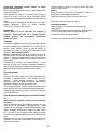
Attenersi strettamente alle istruzioni riportate in questo
manuale. Si declina ogni responsabilità per eventuali
inconvenienti, danni o incendi provocati all'apparecchio
derivati dall'inosservanza delle istruzioni riportate in questo
manuale. La cappa è concepita per l'aspirazione dei fumi e
vapori della cottura ed è destinata al solo uso domestico.
! E' importante conservare questo manuale per poterlo
consultare in ogni momento. In caso di vendita, di
cessione o di trasloco, assicurarsi che resti insieme al
prodotto.
! Leggere attentamente le istruzioni: ci sono importanti
informazioni sull'installazione, sull'uso e sulla sicurezza.
! Non effettuare variazioni elettriche o meccaniche sul
prodotto o sulle condotte di scarico.
! Prima di procedere nell'installazione dell'apparecchio
verificare che tutti i componenti non siano danneggiati. In
caso contrario contattare il rivenditore e non proseguire
con l'installazione.
Nota: I particolari contrassegnati con il simbolo "(*)" sono
accessori opzionali forniti solo in alcuni modelli o particolari
non forniti, da acquistare.
Avvertenze
Attenzione! Non collegare l’apparecchio alla rete elettrica
finche l’installazione non è totalmente completata.
Prima di qualsiasi operazione di pulizia o manutenzione,
disinserire la cappa dalla rete elettrica togliendo la spina o
staccando l’interruttore generale dell’abitazione.
Per tutte le operazioni di installazione e manutenzione
utilizzare guanti da lavoro
L’apparecchio non è destinato all’utilizzo da parte di bambini o
persone con ridotte capacità fisiche sensoriali o mentali e con
mancata esperienza e conoscenza a meno che essi non siano
sotto la supervisione o istruiti nell’uso dell’apparecchiatura da
una persona responsabile per la loro sicurezza.
I bambini devono essere controllati affinché non giochino con
l’apparecchio.
Mai utilizzare la cappa senza griglia correttamente montata!
La cappa non va MAI utilizzata come piano di appoggio a
meno che non sia espressamente indicato.
Il locale deve disporre di sufficiente ventilazione, quando la
cappa da cucina viene utilizzata contemporaneamente ad altri
apparecchi a combustione di gas o altri combustibili.
L’aria aspirata non deve essere convogliata in un condotto
usato per lo scarico dei fumi prodotti da apparecchi a
combustione di gas o di altri combustibili.
E’ severamente vietato fare cibi alla fiamma sotto la cappa.
L’impiego di fiamma libera è dannoso ai filtri e può dar luogo
ad incendi, pertanto deve essere evitato in ogni caso.
La frittura deve essere fatta sotto controllo onde evitare che
l’olio surriscaldato prenda fuoco.
Quando il piano di cottura è in funzione le parti accessibili
della cappa possono diventare calde.
Per quanto riguarda le misure tecniche e di sicurezza da
adottare per lo scarico dei fumi attenersi strettamente a
quanto previsto dai regolamenti delle autorità locali
competenti.
La cappa va frequentemente pulita sia internamente che
esternamente (ALMENO UNA VOLTA AL MESE, rispettare
comunque quanto espressamente indicato nelle istruzioni di
manutenzione riportate in questo manuale).
L’inosservanza delle norme di pulizia della cappa e della
sostituzione e pulizia dei filtri comporta rischi di incendi.
Non utilizzare o lasciare la cappa priva di lampade
correttamente montate per possibile rischio di scossa elettrica.
Si declina ogni responsabilità per eventuali inconvenienti,
danni o incendi provocati all’apparecchio derivati
dall’inosservanza delle istruzioni riportate in questo manuale.
Questo apparecchio è contrassegnato in conformità alla
Direttiva Europea 2002/96/EC, Waste Electrical and Electronic
Equipment (WEEE). Assicurandosi che questo prodotto sia
smaltito in modo corretto, l'utente contribuisce a prevenire le
potenziali conseguenze negative per l'ambiente e la salute.
Il simbolo
sul prodotto o sulla documentazione di
accompagnamento indica che questo prodotto non deve
essere trattato come rifiuto domestico ma deve essere
consegnato presso l'idoneo punto di raccolta per il riciclaggio
di apparecchiature elettriche ed elettroniche. Disfarsene
seguendo le normative locali per lo smaltimento dei rifiuti. Per
ulteriori informazioni sul trattamento, recupero e riciclaggio di
questo prodotto, contattare l'idoneo ufficio locale, il servizio di
raccolta dei rifiuti domestici o il negozio presso il quale il
prodotto è stato acquistato.
Apparecchiatura progettata, testata e realizzata nel rispetto
delle norme sulla:
• Sicurezza: CEI/EN 60335-1; CEI/EN 60335-2-31, CEI/EN
62233.
• Prestazione: CEI/EN 61591; ISO 5167-1; ISO 5167-3; ISO
5168; CEI/EN 60704-1; CEI/EN 60704-2-13; ISO 3741; EN
50564; CEI 62301.
• EMC: EN 55014-1; CISPR 14-1; EN 55014-2; CISPR 14-2;
CEI/EN 61000-3-2; CEI/EN 61000-3-3. Suggerimenti per un
corretto utilizzo al fine di ridurre l’impatto ambientale: Quando
iniziate a cucinare, accendere la cappa alla velocità minima,
lasciandola accesa per alcuni minuti anche dopo il termine
della cottura. Aumentare la velocità solo in caso di grandi
quantità di fumo e vapore, utilizzando la funzione booster solo
in casi estremi. Per mantenere ben efficiente il sistema di
riduzione degli odori, sostituire, quando è necessario, il/i filtro/i
carbone. Per mantenere ben efficiente il filtro del grasso,
pulirlo in caso di necessità. Per ottimizzare l’efficienza e
minimizzare i rumori, utilizzare il diametro massimo del
sistema di canalizzazione indicato in questo manuale.
ATTENZIONE! La mancata installazione di viti e dispositivi di
fissaggio in conformità di queste istruzioni può comportare
rischi di natura elettrica.

8
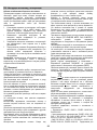
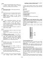
Utilizzazione
La cappa è realizzata per essere utilizzata in versione
aspirante ad evacuazione esterna o filtrante a ricircolo interno.
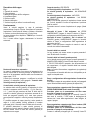
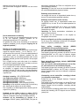
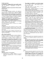
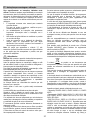
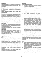
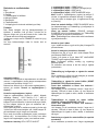
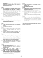
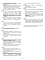
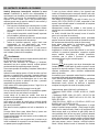
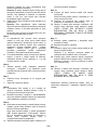
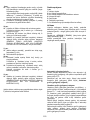
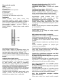
Versione aspirante
La cappa è fornita di una uscita d‘aria superiore B per lo
scarico dei fumi verso l'esterno ( tubo di scarico e fascette di
fissaggio non fornite).
Attenzione! Se la cappa e’ provvista di filtro al carbone,
questo deve essere tolto.
Versione filtrante
Nel caso non sia possibile scaricare i fumi e vapori della
cottura verso l‘esterno, si può utilizzare la cappa in versione
filtrante montando un filtro ai carboni attivi e il deflettore F sul
supporto (staffa) G, i fumi e vapori vengono depurati
attraverso la sgrigliatura superiore H tramite un tubo di scarico
collegato all‘uscita d‘aria superiore B e l‘anello di connessione
montato sul deflettore F (tubo di scarico e fascette di fissaggio
non fornite).
Attenzione! Se la cappa non è provvista di filtro al
carbone, questo deve essere ordinato e montato prima
dell’uso.
I modelli senza motore di aspirazione funzionano solo in
versione aspirante e debbono essere collegati ad una unità
periferica di aspirazione (non fornita).
Le istruzioni di collegamento sono fornite con l'unità periferica
di aspirazione.
Installazione
La distanza minima fra la superficie di supporto dei recipienti
sul dispositivo di cottura e la parte più bassa della cappa da
cucina deve essere non inferiore a 50cm in caso di cucine
elettriche e di 65cm in caso di cucine a gas o miste.
Se le istruzioni di installazione del dispositivo di cottura a gas
specificano una distanza maggiore, bisogna tenerne conto.
Collegamento Elettrico
La tensione di rete deve corrispondere alla tensione riportata
sull’etichetta caratteristiche situata all’interno della cappa. Se
provvista di spina allacciare la cappa ad una presa conforme
alle norme vigenti posta in zona accessibile anche dopo
l’installazione. Se sprovvista di spina (collegamento diretto
alla rete) o la spina non è posta in zona accessibile, anche
dopo installazione, applicare un interruttore bipolare a norma
che assicuri la disconnessione completa della rete nelle
condizioni della categoria di sovratensione III, conformemente
alle regole di installazione.
Attenzione! Prima di ricollegare il circuito della cappa
all’alimentazione di rete e di verificarne il corretto
funzionamento, controllare sempre che il cavo di rete sia stato
montato correttamente.
La cappa è provvista di un cavo alimentazione speciale; in
caso di danneggiamento del cavo, richiederlo al servizio
assistenza tecnica.
Montaggio
Prima di iniziare con l'installazione:
• Verificare che il prodotto acquistato sia di dimensioni
idonee alla zona di installazione prescelta.
• Per agevolare l'installazione, si consiglia di rimuovere
temporaneamente i filtri grassi e gli altri componenti
smontabili come descritto nei paragrafi relativi.
Questi vanno rimontati ad installazione ultimata.
• Togliere il/i filtro/i al carbone attivo se forniti (vedi anche
paragrafo relativo). Questo/i va/nno rimontato/i solo se si
vuole utilizzare la cappa in versione filtrante.
• Verificare che all'interno della cappa non vi sia (per motivi
di trasporto) materiale di corredo (ad esempio buste con
viti, garanzie etc) , eventualmente toglierle e conservarle.
• Se possibile scollegare e rimuovere i mobili sottostanti ed
intorno l’area di installazione della cappa in modo da
avere una migliore accessibilità al/alla soffitto/parete
dove la cappa verrà installata. Altrimenti proteggere per
quanto possibile i mobili e tutte le parti interessate
all'installazione. Scegliere una superficie piatta e coprirla
con una protezione dove poi appoggiare la cappa e i
particolari a corredo.
• Scollegare la cappa agendo sul quadro generale
domestico nelle fasi del collegamento elettrico.
• Verificare inoltre che in prossimità della zona di
installazione della cappa (in zona accessibile anche con
cappa montata) sia disponibile una presa elettrica e sia
possibile collegarsi ad un dispositivo di scarico fumi
verso l'esterno (solo Versione aspirante).
• Eseguire tutti i lavori di muratura necessari (ad es.:
installazione di una presa elettrica e/o foro per il
passaggio del tubo di scarico).
La cappa è dotata di tasselli di fissaggio adatti alla maggior
parte di pareti/soffitti. E’ tuttavia necessario interpellare un
tecnico qualificato per accertarVi sull’idoneità dei materiali a
seconda del tipo di parete/soffitto. La/il parete/soffitto deve
essere sufficientemente robusto da sostenere il peso della
cappa.
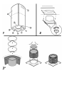
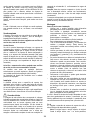
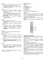
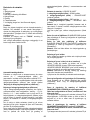
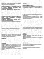
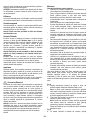
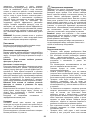
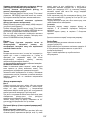
Fig. 4
1. Regolare l’estensione della struttura di supporto della
cappa, da questa regolazione dipenderà la altezza finale
della cappa.
Nota: In alcuni casi la sezione superiore del traliccio è
fissata alla sezione inferiore con 1 o più viti,
eventualmente verificare e toglierle temporaneamente
per permettere la regolazione della struttura di supporto.
2. Fissare le due sezioni della struttura con un totale di 16
viti (4 per angolo).
Nota: Se prevista; togliere temporaneamente le viti che
fissano la staffa di rinforzo al traliccio (conservare le viti)
e appoggiarla sopra il gruppo motore.
La staffa va fissata di nuovo in posizione solo dopo aver
installato il traliccio al soffitto.
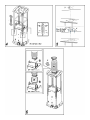
Fig. 5
3. Sulla verticale del piano di cottura, applicare lo schema di

9
foratura al soffitto (il centro dello schema dovrà
corrispondere al centro del piano di cottura ed i lati
dovranno esser paralleli ai lati del piano di cottura-il lato
dello schema con la scritta FRONT (o con le frecce)
corrisponde al lato scatola connessione). Predisporre il
collegamento elettrico.
4. Forare come indicato (4 fori per 4 tasselli a muro),
avvitare 4 viti sui fori indicati sul disegno lasciando uno
spazio tra la testa della vite e il soffitto di circa 1cm.
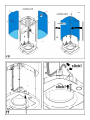
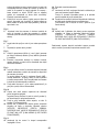
Fig. 6
5. Introdurre un tubo di scarico all’interno del traliccio e
collegarlo all’anello di raccordo del vano motore (tubo di
scarico e fascette di fissaggio non fornite).
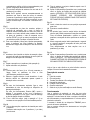
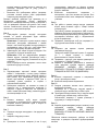
Fig. 7
6. Agganciare il traliccio alle 4 viti (vedi operazione 4).
7. Avvitare con decisione le 4 viti.
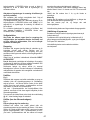
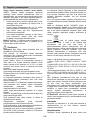
Fig. 8
8. Forare in prossimità dei fori (4 o 6 fori) presenti sulla
flangia, inserire i tasselli a muro e fissare definitivamente
viti e rondelle.
9. Eseguire la connessione elettrica alla rete domestica, la
rete elettrica dovra essere alimentata solo ad
installazione ultimata.
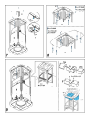
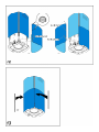
Fig. 9
10. In caso di funzionamento aspirante collegare l’altra
estremità del tubo di scarico al dispositivo di scarico
dell’abitazione.
In caso di funzionamento filtrante (10F) , montare il
deflettore F sul traliccio e fissarlo con 4 viti alla apposita
staffa, collegare infine il tubo di scarico all’anello di
connessione posto sul deflettore.
11. Fissare la staffa di rinforzo (vedi operazione 2) al traliccio
in una posizione il più possibile intermedia.
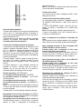
Fig. 10
12. Accoppiare le due sezioni superiori del camino a
copertura del traliccio.
Avvitare ogni singola sezione con 2 viti (1 per lato) in
prossimità del soffitto.
13. Fissare al traliccio l’assieme camino superiore, con 10 viti
(5 per lato).
14. Applicare 2 mostrine (fornite a corredo) a copertura dei
punti di fissaggio delle sezioni del camino superiore
(ATTENZIONE! LE MOSTRINE PER IL CAMINO
SUPERIORE SONO RICONOSCIBILI PERCHE’ PIU’
LARGHE PIU' PROFONDE E CON FISSAGGIO A
PRESSIONE).
Fig. 11
15. Inserire lo stelo di controllo nell'apposita sede
spingendolo verso l'alto.
16. Eseguire la connessione elettrica.
Fig. 12
17. Inserire per prima, la sezione inferiore del camino sulla
quale sono presenti gli inserti filettati.
Fissarla alla struttura avvitando la prima e la quarta vite
partendo dal basso su entrambi i lati.
18. Accoppiare la seconda sezione inferiore avvitando la
seconda e laterza vite partendo dal basso su entrambi i
lati.
Fissare definitivamente le 2 sezioni con 4 viti (2 per lato).
Fig. 13
19. Applicare 2 mostrine (fornite a corredo) a copertura dei
punti di fissaggio delle sezioni del camino inferiore
(ATTENZIONE! LE MOSTRINE PER IL CAMINO
INFERIORE SONO RICONOSCIBILI PERCHE’ PIU’
STRETTE E MENO PROFONDE).
Rialimentare la rete elettrica agendo sul pannello elettrico
centrale e controllare il corretto funzionamento della cappa.

10
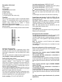
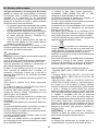
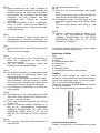
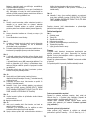
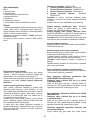
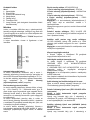
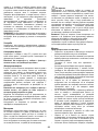
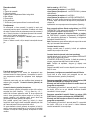
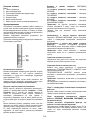
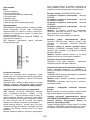
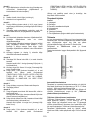
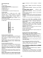
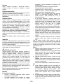
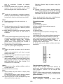
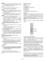
Descrizione della cappa
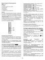
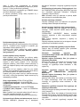
Fig. 1
1. Pannello di controllo
2. Filtro antigrasso
3. Maniglia di sgancio del filtro antigrasso
4. Lampada alogena
5. Schermo vapori
6. Camino telescopico
7. Uscita aria (solo per utilizzo in versione filtrante)
Funzionamento
Usare la velocità maggiore in caso di particolare
concentrazione di vapori di cucina. Consigliamo di accendere
l'aspirazione 5 minuti prima di iniziare a cucinare e di lasciarla
in funzione a cottura terminata per altri 15 minuti circa.
La cappa è dotata di un dispositivo "TOUCH" per il controllo
di luci e velocità.
Per il corretto utilizzo leggere attentamente le istruzioni
sottostanti.
Funzione di accensione automatica
La cappa è equipaggiata di un sensore di temperatura che
attiva il motore alla 1a velocità (potenza) di aspirazione nel
caso in cui la temperatura ambiente nella zona circostante la
cappa superi i 70°C.
L'utente può comunque spegnere o modificare la velocità
(potenza) di aspirazione (vedi paragrafo "Controllo delle
velocità (potenze) di aspirazione").
Controllo delle velocità (potenze) di aspirazione
La selezione delle velocità (potenza) di aspirazione è ciclica
secondo la sequenza velocità "stand-by - 1-2-3-4- Stand by -
1-2-...", perciò ad ogni pressione del tasto T1 dello stelo di
controllo la velocità (potenza) di aspirazione aumenta di un
livello per spegnersi (stand-by) se il tasto viene premuto
ancora quando la cappa è in velocità (potenza) di aspirazione
4.
E' possibile spegnere la cappa (stand by) anche quando la
cappa è in una qualsiasi velocità premendo in maniera
prolungata (più di 3 secondi) il tasto T1 dello stelo di controllo.
E' possibile determinare a quale velocità (potenza) di
aspirazione si trova la cappa in quanto lo stelo è fornito di un
led che cambia colore in base alla velocità (potenza) di
aspirazione come segue:
Cappa in stand-by: LED SPENTO
1a velocità (potenza) di aspirazione - led VERDE
2a velocità (potenza) di aspirazione - led ARANCIONE
(ambra)
3a velocità (potenza) di aspirazione - led ROSSO
4a velocità (potenza) di aspirazione - led ROSSO
LAMPEGGIANTE)
Nota: la 4a velocità (potenza) di aspirazione rimane accesa
per 5 minuti, dopodichè il motore di aspirazione si posiziona
sulla 2a velocità.
Premendo ancora il motore di aspirazione si spegne (Stand
by).
Necessità di lavare i filtri antigrasso: led VERDE
LAMPEGGIANTE (leggere le istruzioni relative al "Reset e
configurazione della segnalazione di saturazione dei filtri")
Necessità di lavare o sostituire i filtri al carbone: led
ARANCIO (ambra) LAMPEGGIANTE (leggere le istruzioni
relative al "Reset e configurazione della segnalazione di
saturazione dei filtri")
Nota: Il reset può essere eseguito sia tramite lo stelo di
controllo che tramite il telecomando.
Controllo della luce centrale
La luce centrale può essere accesa e spenta premendo il
tasto T2 dello stelo di controllo.
Controllo delle luci laterali (quando previste)
Le luci laterali possono essere accese e spente premendo IN
MANIERA PROLUNGATA il tasto T2 dello stelo di controllo.
Il TOCCO PROLUNGATO permette, oltre all'accensione ed
allo spegnimento, di regolare l'intensità della luce emessa
dalle lampade.
Nota: Le funzioni di accensione, spegnimento (e regolazione)
si alternano.
La regolazione di intensità della luce non è disponibile per le
cappe con lampade neon.
Reset e configurazione della segnalazione di saturazione
dei filtri
Accendere la cappa ad una qualsiasi velocità (vedi paragrafo
sopra “Selezione delle velocità (potenze) di aspirazione”)
Reset segnalazione saturazione del filtro antigrasso (LED
VERDE LAMPEGGIANTE sullo stelo di controllo)
Procedere prima con la manutenzione del filtro come
descritto nel paragrafo corrispondente.
Premere in maniera prolungata (più di 3 secondi) il tasto T1
dello stelo di controllo, il LED smette di lampeggiare ad
indicare che il reset della segnalazione è stato eseguito, la
cappa si spegne.
Reset segnalazione saturazione del filtro al carbone (LED
ARANCIO (ambra) LAMPEGGIANTE)
Procedere prima con la manutenzione del filtro come
descritto nel paragrafo corrispondente.
Premere in maniera prolungata (più di 3 secondi) il tasto T1

11
dello stelo di controllo, il LED smette di lampeggiare ad
indicare che il reset della segnalazione è stato eseguito, la
cappa si spegne.
Disattivazione della segnalazione di saturazione del filtro
al carbone (per applicazioni particolari)
Spegnere la cappa (vedi paragrafo sopra “Selezione delle
velocità (potenze) di aspirazione”)
Premere in maniera prolungata (più di 5 secondi) il tasto T1
dello stelo di controllo, il LED lampeggerà in VERDE ad
indicare che è stata disattivata la segnalazione di saturazione
del filtro al carbone.
Per riattivare la segnalazione di saturazione del filtro al
carbone, ripetere l’operazione, il LED lampeggerà in
ARANCIO (ambra).
Manutenzione
Attenzione! Prima di qualsiasi operazione di pulizia o
manutenzione, disinserire la cappa dalla rete elettrica
togliendo la spina o staccando l’interruttore generale
dell’abitazione.
Pulizia
La cappa va frequentemente pulita (almeno con la stessa
frequenza con cui si esegue la manutenzione dei filtri grassi),
sia internamente che esternamente. Per la pulizia usare un
panno inumidito con detersivi liquidi neutri.
Evitare l’uso di prodotti contenenti abrasivi. NON UTILIZZARE
ALCOOL!
Attenzione: L’inosservanza delle norme di pulizia
dell’apparecchio e della sostituzione dei filtri comporta rischi di
incendi. Si raccomanda quindi di attenersi alle istruzioni
suggerite.
Si declina ogni responsabilità per eventuali danni al motore,
incendi provocati da un’impropria manutenzione o
dall’inosservanza delle suddette avvertenze.
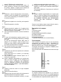
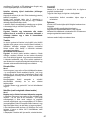
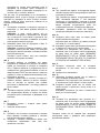
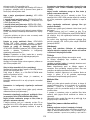
Filtro antigrasso
Fig. 2
Deve essere pulito una volta al mese (o quando il sistema di
indicazione di saturazione dei filtri - se previsto sul modello in
possesso- indica questa necessità), con detergenti non
aggressivi, manualmente oppure in lavastoviglie a basse
temperature ed a ciclo breve.
Con il lavaggio in lavastoviglie il filtro antigrasso metallico può
scolorirsi ma le sue caratteristiche di filtraggio non cambiano
assolutamente.
Rimuovere il telaio reggi filtro girando di 90° i pomelli (g) che
lo fissano alla cappa.
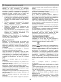
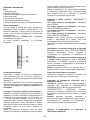
Filtro ai carboni attivi (Solo per Versione Filtrante)
Fig. 3
Trattiene gli odori sgradevoli derivanti dalla cottura.
Il filtro al carbone può essere lavato ogni due mesi (o quando
il sistema di indicazione di saturazione dei filtri - se previsto
sul modello in possesso- indica questa necessità) in acqua
calda e detergenti idonei o in lavastoviglie a 65°C (in caso di
lavaggio in lavastoviglie eseguire il ciclo di lavaggio completo
senza stoviglie all'interno).
Togliere l'acqua in eccesso senza rovinare il filtro, dopodiché
riporlo nel forno per 10 minuti a 100°C per asciugarlo
definitivamente.
Sostituire il materassino ogni 3 anni e ogni volta che il panno
risulta danneggiato.
Montaggio
Posizionare il materassino intorno al filtro grassi e fissarlo con
gli appositi dispositivi di bloccaggio.
Applicare il tappo superiore e fissarlo con la molla di
bloccaggio.
Per lo smontaggio procedere nel senso inverso.
Sostituzione Lampade
La cappa è dotata di un sistema di illuminazione basato sulla
tecnologia LED.
I LED garantiscono una illuminazione ottimale, una durata fino
a 10 volte maggiore delle lampade tradizionali e consentono
di risparmiare il 90% di energia elettrica.
Per la sostituzione rivolgersi al servizio assistenza tecnica.

12
EN - Instruction on mounting and use
Closely follow the instructions set out in this manual. All
responsibility, for any eventual inconveniences, damages or
fires caused by not complying with the instructions in this
manual, is declined. The hood is conceived for the suction of
cooking fumes and steam and is destined only for domestic
use.
! It is important to conserve this booklet for consultation at
any moment. In the case of sale, cession or move, make
sure it is together with the product.
! Read the instructions carefully: there is important
information about installation, use and safety.
! Do not carry out electrical or mechanical variations on the
product or on the discharge conduits.
! Before proceeding with the installation of the appliance
verify that there are no damaged all components.
Otherwise contact your dealer and do not proceed with
the installation.
Note: the elements marked with the symbol “(*)” are optional
accessories supplied only with some models or elements to
purchase, not supplied.
Caution
WARNING! Do not connect the appliance to the mains until
the installation is fully complete.
Before any cleaning or maintenance operation, disconnect
hood from the mains by removing the plug or disconnecting
the mains electrical supply.
Always wear work gloves for all installation and maintenance
operations.
The appliance is not intended for use by children or persons
with impaired physical, sensorial or mental faculties, or if
lacking in experience or knowledge, unless they are under
supervision or have been trained in the use of the appliance
by a person responsible for their safety.
This appliance is designed to be operated by adults, children
should be monitored to ensure that they do not play with the
appliance.
This appliance is designed to be operated by adults. Children
should not be allowed to tamper with the controls or play with
the appliance.
Never use the hood without effectively mounted grating!
The hood must NEVER be used as a support surface unless
specifically indicated.
The premises where the appliance is installed must be
sufficiently ventilated, when the kitchen hood is used together
with other gas combustion devices or other fuels.
The ducting system for this appliance must not be connected
to any existing ventilation system which is being used for any
other purpose such as discharging exhaust fumes from
appliances burning gas or other fuels.
The flaming of foods beneath the hood itself is severely
prohibited.
The use of exposed flames is detrimental to the filters and
may cause a fire risk, and must therefore be avoided in all
circumstances.
Any frying must be done with care in order to make sure that
the oil does not overheat and ignite.
Accessible parts of the hood may became hot when used with
cooking appliance.
With regards to the technical and safety measures to be
adopted for fume discharging it is important to closely follow
the regulations provided by the local authorities.
The hood must be regularly cleaned on both the inside and
outside (AT LEAST ONCE A MONTH).
This must be completed in accordance with the maintenance
instructions provided in this manual). Failure to follow the
instructions provided in this user guide regarding the cleaning
of the hood and filters will lead to the risk of fires.
Do not use or leave the hood without the lamp correctly
mounted due to the possible risk of electric shocks.
We will not accept any responsibility for any faults, damage or
fires caused to the appliance as a result of the non-
observance of the instructions included in this manual.
This appliance is marked according to the European directive
2002/96/EC on Waste Electrical and Electronic Equipment
(WEEE). By ensuring this product is disposed of correctly, you
will help prevent potential negative consequences for the
environment and human health, which could otherwise be
caused by inappropriate waste handling of this product.
The symbol
on the product, or on the documents
accompanying the product, indicates that this appliance may
not be treated as household waste. Instead it should be taken
to the appropriate collection point for the recycling of electrical
and electronic equipment. Disposal must be carried out in
accordance with local environmental regulations for waste
disposal.
For further detailed information regarding the process,
collection and recycling of this product, please contact the
appropriate department of your local authorities or the local
department for household waste or the shop where you
purchased this product.
Appliance designed, tested and manufactured according to:
• Safety: EN/IEC 60335-1; EN/IEC 60335-2-31, EN/IEC
62233.
• Performance: EN/IEC 61591; ISO 5167-1; ISO 5167-3; ISO
5168; EN/IEC 60704-1; EN/IEC 60704-2-13; ISO 3741; EN
50564; IEC 62301.
• EMC: EN 55014-1; CISPR 14-1; EN 55014-2; CISPR 14-2;
EN/IEC 61000-3-2; EN/IEC 61000-3-3. Suggestions for a
correct use in order to reduce the environmental impact:
Switch ON the hood at minimum speed when you start
cooking and kept it running for few minutes after cooking is
finished. Increase the speed only in case of large amount of
smoke and vapour and use boost speed(s) only in extreme
situations. Replace the charcoal filter(s) when necessary to
maintain a good odour reduction efficiency. Clean the grease
filter(s) when necessary to maintain a good grease filter
efficiency. Use the maximum diameter of the ducting system
indicated in this manual to optimize efficiency and minimize

13
noise.
Additional Installation Specifications:
Use only the fixing screws supplied with the product for
installation or, if not supplied, purchase the correct screws
type.
Use the correct length for the screws which are identified in
the Installation Guide.
In case of doubt, consult an authorised service assistance
centre or similar qualified person.
WARNING! Failure to install the screws or fixing device in
accordance with these instructions may result in electrical
hazards.
Use
The hood is designed to be used either for exhausting or filter
version.
Ducting version
The hood is equipped with a top air outlet B for discharge of
fumes to the outside (exhaust pipe and pipe fixing clamps not
provided).
Attention! If the hood is supplied with carbon filter, then it
must be removed.
Filter version
Should it not be possible to discharge cooking fumes and
vapour to the outside, the hood can be used in the filter
version, fitting an activated carbon filter and the deflector F
on the support (bracket) G, fumes and vapours are recycled
through the top grille H by means of an exhaust pipe
connected to the top air outlet B and the connection ring
mounted on the deflector F (exhaust pipe and pipe fixing
clamps not provided).
Attention! If the hood is not supplied with carbon filter,
then it must be ordered and mounted.
The models with no suction motor only operate in ducting
mode, and must be connected to an external suction device
(not supplied).
The connecting instructions are supplied with the peripheral
suction unit.
Installation
The minimum distance between the supporting surface for the
cooking equipment on the hob and the lowest part of the
range hood must be not less than 50cm from electric cookers
and 65cm from gas or mixed cookers.
If the instructions for installation for the gas hob specify a
greater distance, this must be adhered to.
Electrical connection
The mains power supply must correspond to the rating
indicated on the plate situated inside the hood. If provided with
a plug connect the hood to a socket in compliance with current
regulations and positioned in an accessible area, after
installation. If it not fitted with a plug (direct mains connection)
or if the plug is not located in an accessible area, after
installation, apply a double pole switch in accordance with
standards which assures the complete disconnection of the
mains under conditions relating to over-current category III, in
accordance with installation instructions.
Warning! Before re-connecting the hood circuit to the mains
supply and checking the efficient function, always check that
the mains cable is correctly assembled.
The hood is provided with a special power cable ; if the cable
is damaged, request a new one from Technical Service.
Mounting
Before beginning installation:
• Check that the product purchased is of a suitable size for
the chosen installation area.
• To facilitate installation, remove the fat filters and the
other parts allowed and described here, dismantle and
mount it.
To remove see also the relative paragraphs.
• Remove the active carbon (*) filter/s if supplied (see also
relative paragraph). This/these is/are to be mounted only
if you want lo use the hood in the filtering version.
• Check (for transport reasons) that there is no other
supplied material inside the hood (e.g. packets with
screws (*), guarantees (*), etc.), eventually removing
them and keeping them.
• If possible, disconnect and move freestanding or slide-in
range from cabinet opening to provide easier access to
rear wall/ceiling. Otherwise put a thick, protective
covering over countertop, cooktop or range to protect
from damage and debris. Select a flat surface for
assembling the unit. Cover that surface with a protective
covering and place all canopy hood parts and hardware
in it.
• Disconnect the hood during electrical connection, by
turning the home mains switch off.
• In addition check whether near the installation area of the
hood (in the area accessible also with the hood mounted)
an electric socket is available and it is possible to
connect a fumes discharge device to the outside (only
suction version).
• Carry out all the masonry work necessary (e.g.
installation of an electric socket and/or a hole for the
passage of the discharge tube).
Expansion wall plugs are provided to secure the hood to most
types of walls/ceilings. However, a qualified technician must
verify suitability of the materials in accordance with the type of
wall/ceiling. The wall/ceiling must be strong enough to take
the weight of the hood. Do not tile, grout or silicone this
appliance to the wall. Surface mounting only.
Fig. 4
1. Adjust extension of the hood support structure, as the
final height of the hood depends on this.
Note: In some cases the upper section of the lattice is
fixed to the lower section with one or more screws,
eventually check and remove them temporarily to allow
the adjustment of the support structure.
2. Fix the two sections of the structure with a total of 16
screws (four per corner).
Note: If supplied, temporarily remove the screws fixing
the reinforcement bracket to the perforated frame (keep

14
these screws in a safe place) and position it over the
motor assembly.
The bracket should be fixed in place again only after the
perforated frame has been fitted to the ceiling.
Fig. 5
3. Apply the drilling template to the ceiling so that it is
vertically in line with the hob (the centre of the template
should be aligned with the centre of the hob and the
sides should run parallel to the sides of the hob; the side
of the template displaying the text FRONT (or the arrows)
should correspond to the connection box side). Make the
electrical connection.
4. Make holes as indicated (4 holes for 4 wall dowels), Screw
in 4 screws into the holes indicated in the drawing leaving
a space between the head of the screw and the ceiling of
about 1 cm.
Fig. 6
5. Fit an exhaust pipe inside the truss and connect it to the
motor compartment connection ring (exhaust pipe and
fixing brackets are not supplied).
Fig. 7
6. Hook the frame onto the 4 screws (see step 4).
7. Tighten the 4 screws.
Fig. 8
8. Drill around the holes (4 or 6 holes) on the flange, fit the
rawl plugs into the wall and fix the screws and washers in
place.
9. Carry out the electrical connection to the mains power
supply, only turn on the power supply upon completion of
assembly.
Fig. 9
10. For extractor versions, connect the other end of the
exhaust pipe to the flue.
For filter versions (10F), fit deflector F to the truss and
secure it to the bracket supplied using 4 screws, then
connect the exhaust pipe to the connection ring located on
the deflector.
11. Fix the reinforcement bracket (see step 2) to the
perforated frame in a position which is as near to the
middle as possible.
Fig. 10
12. Join the two upper sections of the duct covering the
perforated frame.
Fix each individual section in place using 2 screws (1 per
side) near the ceiling.
13. Fix the upper duct to the perforated frame using 10
screws (5 per side).
14. Apply 2 casings (supplied) to cover the fixing points on
the upper duct sections (CAUTION: THE UPPER DUCT
CASINGS ARE EASY TO RECOGNISE BECAUSE
THEY ARE WIDER, DEEPER AND ARE FITTED BY
PRESSING THEM INTO PLACE).
Fig. 11
15. Fit the control shaft in the correct position by pushing it
upwards.
16. Connect the electricity.
Fig. 12
17. First insert the lower section of the duct, on which the
threaded inserts can be found.
Fix it to the frame, tightening the first and fourth screws
on both sides (counting from the bottom).
18. Join the second lower section by tightening the second
and third screws on each side (counting from the
bottom).
Fix the 2 sections in place using 4 screws (2 per side).
Fig. 13
19. Apply 2 casings (supplied) to cover the fixing points on
the lower duct sections (CAUTION: THE LOWER DUCT
CASINGS ARE EASY TO RECOGNISE BECAUSE
THEY ARE NARROWER AND LESS DEEP).
Turn the mains power on again at the central electrical panel
and check for correct hood operation.

15
Description of the hood
Fig. 1
1. Control panel
2. Grease filter
3. Grease filter release handle
4. Halogen lamp
5. Vapour catcher
6. Telescopic chimney
7. Air outlet (used for filter version only)
Operation
Use the high suction speed in cases of concentrated kitchen
vapours. It is recommended that the cooker hood suction is
switched on for 5 minutes prior to cooking and to leave in
operation during cooking and for another 15 minutes
approximately after terminating cooking.
The hood is equipped with a “TOUCH” device to control the
lights and speed.
For the correct use please carefully read the intructions below.
Automatic start-up function
The hood is equipped with a temperature sensor which
activates the motor to the first suction speed (power) in the
event that the temperature in the surrounding area is higher
than 70°C.
The user may switch off or modify the suction speed (power)
(see paragraph “suction speed (power) control”).
Suction speed (power) control
The suction speed (power) is cyclical depending on the speed
sequence “stand-by – 1-2-3-4- Stand by -1-2-...” therefore
every time the T1 button is pressed on the control panel, the
suction speed (power) is increased by one level, in order to
switch off (stand-by) if the button is pressed again when the
hood is in suction speed (power) 4.
The hood may be switched off (stand-by) while the hood is set
on any speed by holding down the T1 button on the control
panel for a bit longer (more than 3 seconds).
The hood's suction speed (power) may be determined as the
control panel is equipped with a LED light that changes colors
as follows, depending on the suction speed (power):
Hood in stand-by: LED LIGHT SWITCHED OFF
1
st
suction speed (power) -GREEN LED LIGHT
2
nd
suction speed (power) – ORANGE LED LIGHT (amber)
3
rd
suction speed (power) - RED LED LIGHT
4
th
suction speed (power) - RED LED LIGHT (FLASHING)
Note: The 4
th
suction speed (power) stays on for 5 minutes,
after which the suction motor will position itself on the 2
nd
speed.
If pressed again, the suction motor will switch off (stand-by).
Grease filters need cleaning: FLASHING GREEN LED light
(read instructions found under “Reset and configuration for
filter saturation signal”)
Coal filters must be cleaned or replaced: FLASHING
ORANGE (amber) LED light (read instructions found under
“Reset and configuration for filter saturation signal”)
Note: The reset procedure may be activated by both the
control panel and the remote control.
Center light check
The center light may be switched on and off by pressing the
T2 button on the control panel.
Side light check (when scheduled)
The side lights may be switched on and off by pressing AND
HOLDING DOWN the T2 button on the control panel.
HOLDING DOWN the button, besides permitting to switch the
hood on and off, it also regulates the light intensity given from
the lights.
Note: The switching on and off functions (and regulating
function) alternate.
The regulation of the light intensity is not available for hoods
with neon lights.
Reset and configuration for filter saturation signal
Switch on hood to any speed (see above paragraph “Suction
speed (power) selection”)
Reset grease filter saturation signal (FLASHING GREEN
LIGHT on control panel)
First proceed with filter maintenance as described in
corresponding paragraph.
Press and hold down (for more than 3 seconds) the T1 button
on the control panel, the LED light will stop flashing indicating
that the signal reset has been carried out, the hood will switch
off.
Reset coal filter saturation signal (FLASHING ORANGE
(amber) LED light)
First proceed with filter maintenance as described in
corresponding paragraph.
Press and hold down (for more than 3 seconds) the T1 button
on the control panel, the LED light will stop flashing indicating
that the signal reset has been carried out, the hood will switch
off.
Coal filter saturation signal disactivaction (for particular
applications)

16
Switch off hood (see above paragraph “suction speed (power)
selection”).
Press and hold down (for more than 5 seconds) the T1 button
on the control panel, the LED light will start flashing GREEN
indicating that the coal filter saturation signal has been
disactivated.
In order to reactivate the coal filter saturation signal, repeat
operation, the LED light will flash ORANGE (amber)
Maintenance
ATTENTION! Before performing any maintenance operation,
isolate the hood from the electrical supply by switching off at
the connector and removing the connector fuse.
Or if the appliance has been connected through a plug and
socket, then the plug must be removed from the socket.
Cleaning
The cooker hood should be cleaned regularly (at least with the
same frequency with which you carry out maintenance of the
fat filters) internally and externally. Clean using the cloth
dampened with neutral liquid detergent. Do not use abrasive
products. DO NOT USE ALCOHOL!
WARNING: Failure to carry out the basic cleaning
recommendations of the cooker hood and replacement of the
filters may cause fire risks.
Therefore, we recommend observing these instructions.
The manufacturer declines all responsibility for any damage to
the motor or any fire damage linked to inappropriate
maintenance or failure to observe the above safety
recommendations.
Grease filter
Fig. 2
This must be cleaned once a month (or when the filter
saturation indication system – if envisaged on the model in
possession – indicates this necessity) using non aggressive
detergents, either by hand or in the dishwasher, which must
be set to a low temperature and a short cycle.
When washed in a dishwasher, the grease filter may discolour
slightly, but this does not affect its filtering capacity.
Remove the filter holder frame by turning the knobs (g) 90°
that affix the chimney to the cooker hood.
Charcoal filter (filter version only)
Fig. 3
It absorbs unpleasant odours caused by cooking.
The charcoal filter can be washed once every two months (or
when the filter saturation indication system – if envisaged on
the model in possession – indicates this necessity) using hot
water and a suitable detergent, or in a dishwasher at 65°C (if
the dishwasher is used, select the full cycle function and leave
dishes out).
Eliminate excess water without damaging the filter, then put it
in the oven for 10 minutes at 100° C to dry completely.
Replace the mattress every 3 years and when the cloth is
damaged.
Assembly
Place the mat around the grease filter and fix it in place using
the devices provided.
Position the upper cap and fix it in place using the fixing pin.
To disassemble, perform the steps in the reverse order.
Replacing lamps
The hood is equipped with a lighting system based on LED
technology.
The LEDs guarantee an optimum lighting, a duration up to 10
times as long as the traditional lamps and allow to save 90%
electrical energy.
For replacement, contact the technical service.

17
DE - Montage- und Gebrauchsanweisung
Die Anweisungen, die in diesem Handbuch gegeben
werden, müssen strikt eingehalten werden. Es wird
keinerlei Haftung übernommen für mögliche Mängel, Schäden
oder Brände der Dunstabzugshaube, die auf die
Nichtbeachtung der Vorschriften in diesem Handbuch
zurückzuführen sind. Die Dunstabzugshaube wurde für die
Absaugung der beim Kochen entstehenden Dünste und
Dämpfe entwickelt. Sie ist nur für den Hausgebrauch
geeignet.
! Die Bedienungsanleitung muss aufbewahrt werden,
damit jederzeit ein Nachschlagen möglich ist. Bei
Verkauf, Abtretung oder Umzug muss die
Bedienungsanleitung immer beim Produkt bleiben.
! Die Bedienungsanleitung muss aufmerksam gelesen
werden, da sie wichtige Informationen über Installation,
Gebrauch und Sicherheit enthält.
! Es dürfen keine elektrischen oder mechanischen
Änderungen am Gerät oder an den Abluftleitungen
vorgenommen werden.
! Vergewissern Sie sich vor der Installation, dass das
Gerät keine Transportschäden aufweist. Bei auftretenden
Problemen setzen Sie sich bitte mit Ihrem Händler in
Verbindung.
Hinweis: Die mit dem (*) gekennzeichneten Teile sind
Zubehörteile, die nur bei einigen Modellen im Lieferumfang
enthalten sind oder Teile, die nicht im Lieferumfang enthalten
sind, und somit extra erworben werden müssen.
Warnung
Achtung! Das Gerät nicht an das Stromnetz anschließen,
solange die Installation noch nicht abgeschlossen ist.
Vor Beginn sämtlicher Reinigungs- oder Wartungsarbeiten
muss das Gerät durch Ziehen des Steckers oder Betätigen
des Hauptschalters der Wohnung vom Stromnetz getrennt
werden.
Bei allen Installations- und Instandhaltungsarbeiten immer
Schutzhandschuhe tragen.
Kinder nicht mit dem Gerät spielen lassen.
Erwachsene und Kinder dürfen nie unbeaufsichtigt das Gerät
benutzen,
– wenn sie körperlich oder geistig dazu nicht in der Lage sind,
– oder wenn ihnen Wissen und Erfahrung fehlen, das Gerät
richtig und sicher zu bedienen.
Die Dunstabzugshaube niemals ohne korrekt montiertes Gitter
in Betrieb setzen!
Die Dunstabzugshaube darf NIEMALS als Abstellfläche
verwendet werden, sofern dies nicht ausdrücklich angegeben
wird.
Der Raum muss über eine hinreichende Belüftung verfügen,
wenn die Dunstabzugshaube mit anderen gas- oder
brennstoffbetriebenen Geräten gleichzeitig verwendet wird.
Bei gleichzeitigem Betrieb der Dunstabzugshaube im
Abluftbetrieb und gas- oder brennstoffbetriebenen Geräten
darf im Aufstellraum gas- oder brennstoffbetriebenen Geräten
der Unterdruck nicht größer als 4 Pa (4 x 10
-5
bar) sein.
Die angesaugte Luft darf nicht in Rohre geleitet werden, die
für die Ableitung der Abgase von gas- oder
brennstoffbetriebenen Geräten genutzt werden.
Es ist strengstens verboten, unter der Haube mit offener
Flamme zu kochen.
Eine offene Flamme beschädigt die Filter und kann Brände
verursachen und muss deshalb strikt vermieden werden.
Das Frittieren muss unter Aufsicht erfolgen, um zu vermeiden,
dass das überhitzte Öl Feuer fängt.
Zugängliche Teile können beim Gebrauch mit Kochgeräten
heiß werden.
In Bezug auf technische Maßnahmen und
Sicherheitsmaßnahmen für die Ableitung der Abluft sind die
Vorschriften der zuständigen örtlichen Behörden strengstens
einzuhalten.
Die Haube muss regelmäßig innen und außen gereinigt
werden (MINDESTENS EINMAL IM MONAT, diesbezüglich
sind in jedem Fall die ausdrücklichen Angaben in der
Wartungsanleitung dieses Handbuchs zu beachten).
Eine Nichtbeachtung der Vorschriften zur Reinigung der
Haube sowie zum Auswechseln und Reinigen der Filter führt
zu Brandgefahr.
Um das Risiko eines Stromschlages zu vermeiden, darf die
Dunstabzugshaube ohne richtig eingesetzte Lampen nicht
betrieben werden.
Es wird keinerlei Haftung übernommen für Fehler, Schäden
oder Brände des Gerätes, die durch Nichteinhaltung der in
diesem Handbuch aufgeführten Anweisungen verschuldet
wurden.
In Übereinstimmung mit den Anforderungen der Europäischen
Richtlinie 2002/96/EG über Elektro- und Elektronik-Altgeräte
(WEEE) ist vorliegendes Gerät mit einer Kennzeichnung
versehen.
Sie leisten einen positiven Beitrag für den Schutz der Umwelt
und die Gesundheit des Menschen, wenn Sie dieses Gerät
einer gesonderten Abfallsammlung zuführen. Im unsortierten
Siedlungsmüll könnte ein solches Gerät durch unsachgemäße
Entsorgung negative Konsequenzen nach sich ziehen.
Auf dem Produkt oder der beiliegenden
Produktdokumentation ist folgendes Symbol
einer
durchgestrichenen Abfalltonne abgebildet. Es weist darauf
hin, dass eine Entsorgung im normalen Haushaltsabfall nicht
zulässig ist. Entsorgen Sie dieses Produkt im Recyclinghof mit
einer getrennten Sammlung für Elektro- und Elektronikgeräte.
Die Entsorgung muss gemäß den örtlichen Bestimmungen zur
Abfallbeseitigung erfolgen.
Bitte wenden Sie sich an die zuständigen Behörden Ihrer
Gemeindeverwaltung, an den lokalen Recyclinghof für
Haushaltsmüll oder an den Händler, bei dem Sie dieses Gerät
erworben haben, um weitere Informationen über Behandlung,
Verwertung und Wiederverwendung dieses Produkts zu
erhalten.
Gerät entwickelt, getestet und hergestellt nach:

18
•Safety: EN/IEC 60335-1; EN/IEC 60335-2-31, EN/IEC 62233.
•Performance: EN/IEC 61591; ISO 5167-1; ISO 5167-3; ISO
5168; EN/IEC 60704-1; EN/IEC 60704-2-13; ISO 3741; EN
50564; IEC 62301.
•EMC: EN 55014-1; CISPR 14-1; EN 55014-2; CISPR 14-2;
EN/IEC 61000-3-2; EN/IEC 61000-3-3. Empfehlungen für eine
korrekte Verwendung, um die Umweltbelastung zu verringern:
Schalten Sie Haube beim Kochbeginn bei kleinster
Geschwindigkeit EIN und lassen Sie die Haube einige
Minuten nachlaufen, wenn Sie mit dem Kochen fertig sind.
Erhöhen Sie die Geschwindigkeit nur bei großen Mengen von
Kochdunst und Dampf und benutzen Sie die Intesivstufe(n)
nur bei extemen Situationen. Wechseln Sie die Kohlefilter,
wenn notwendig, um eine gute Geruchsreduzierung zu
gewährleisten. Säubern Sie die Fettfilter, wenn notwendig,
um eine gute Fettfilterungseffizienz zu gewährleisten.
Verwenden Sie den in der Gebrauchsanweisung
angegebenen grössten Durchmesser des
Luftaustrittssystems, um die Leistungsfähigkeit zu optimieren
und die Geräuschentwicklung zu minimieren.
WARNUNG! Erfolgt die Installation der Schrauben oder
Befestigungsvorrichtungen nicht entsprechend den
vorliegenden Anweisungen, führt dies zu Gefahr durch
Stromschlag.
Betriebsart
Die Haube kann sowohl als Abluftgerät als auch als
Umluftgerät eingesetzt werden.
Abluftbetrieb
Die Haube verfügt über einen oberen Luftaustritt B zum
Ableiten der Küchengerüche nach außen (Abluftrohr und
Rohrschellen werden nicht geliefert).
Achtung! Sollte die Dunstabzugshaube mit einem
Aktivkohlefilter versehen sein, so muß dieser entfernt
werden.
Umluftbetrieb
Ist eine Ableitung von Rauch und Kochdämpfen ins Freie nicht
möglich, kann die Haube mit Umluftbetrieb arbeiten; in
diesem Fall muß ein Aktivkohlefilter bzw. ein Umleitgitter F an
der Halterung (Bügel) G montiert werden; auf diese Weise
wird die Luft durch das obere Gitter H mit Hilfe eines
Abluftrohres, das an den oberen Luftaustritt B angeschlossen
ist, und eines Anschlussrings am Umleitgitter F (Abluftrohr
und Rohrschellen sind nicht im Lieferumfang enthalten)
rückgeführt.
Achtung! Sollte die Dunstabzugshaube nicht mit einem
Aktivkohlefilter versehen sein, ist dieser zu bestellen und
vor Inbetriebnahme des Gerätes einzusetzen.
Modelle ohne Saugmotor funktionieren nur mit Abluftbetrieb
und müssen an eine externe Saugeinheit (nicht im
Lieferumfang enthalten) angeschlossen werden.
Die Anschlussanleitungen liegen der externe Saugeinheit bei.
Befestigung
Der Abstand zwischen der Abstellfläche auf dem Kochfeld und
der Unterseite der Dunstabzugshaube darf 50cm im Fall von
elektrischen Kochfeldern und 65cm im Fall von Gas- oder
kombinierten Herden nicht unterschreiten.
Wenn die Installationsanweisungen des Gaskochgeräts einen
größeren Abstand vorgeben, ist dieser zu berücksichtigen.
Elektrischer Anschluss
Die Netzspannung muss der Spannung entsprechen, die auf
dem Betriebsdatenschild im Innern der Haube angegeben ist.
Sofern die Haube einen Netzstecker hat, ist dieser an
zugänglicher Stelle an eine den geltenden Vorschriften
entsprechende Steckdose nach der Montage anzuschließen.
Bei einer Haube ohne Stecker (direkter Netzanschluss) oder
falls der Stecker nicht zugänglich ist, ist ein normgerechter
zweipoliger Schalter nach der Montage anzubringen, der unter
Umständen der Überspannung Kategorie III entsprechend den
Installationsregeln ein vollständiges Trennen vom Netz
garantiert.
Hinweis! Vor der Inbetriebnahme muss sichergestellt werden,
dass die Netzversorgungleitung (Steckdose) ordnungsgemäß
montiert wurde.
Die Dunstabzugshaube ist mit einem Spezialkabel
ausgestattet. Sollte das Kabel beschädigt werden, muss beim
Kundendienst Ersatz angefordert werden.
Montage
Bevor Sie mit der Montage beginnen:
• Überprüfen Sie, dass das erstandene Produkt von der
Größe her dem Bereich entspricht, in dem es angebracht
werden soll.
• Um die Montage zu vereinfachen, wird empfohlen, die
Fettfilter und andere Teile, die laut den vorliegenden
Anweisungen ein- und ausgebaut werden können,
zeitweise zu entfernen.
• Entfernen Sie den/die Aktivkohlefilter (*), falls vorhanden
(siehe hierzu auch den entsprechenden Absatz
"Wartung"). Der/die Aktivkohlefilter wird/werden nur
wieder in die Dunstabzugshaube eingesetzt, wenn diese
im Umluftbetrieb verwendet werden soll.
• Vergewissern Sie sich, dass sich im Inneren der
Dunstabzugshaube (aus Transportgründen) kein im
Lieferumfang enthaltenes Material (zum Beispiel Tütchen
mit Schrauben (*), die Garantie (*), usw.) befindet; falls
vorhanden, entfernen Sie dieses und heben Sie sie auf.
• Falls möglich, entfernen Sie die Möbel unter und um die
Dunstabzugshaube herum, um besseren Zugriff auf die
hintere Wand/Decke zu haben, wo die Haube angebracht
wird. Sonst legen Sie bitte eine Schutzabdeckung auf die
Kochplatte, Arbeitsfläche, sowie die Möbel und Wände,
um sie vor Schäden oder Schmutz zu schützen. Wählen
Sie eine ebene Oberfläche, um die Einheit
zusammenzubauen. Decken Sie diese Oberfläche mit
einer Schutzfolie ab und legen Sie die
Dunstabzugshaube sowie alle im Lieferumfang
enthaltenen Teile darauf.
• Vor dem Anschluss des Gerätes ist die Sicherung der
Steckdose auszuschalten
• Vergewissern Sie sich zudem, dass in der Nähe der
Fläche, an der die Dunstabzugshaube angebracht
werden soll (eine Fläche, die auch nach der Montage der

19
Dunstabzugshaube weiter zugänglich sein muss), eine
Steckdose vorhanden ist und es möglich ist, die
Dunstabzugshaube an eine Vorrichtung zum Ableiten der
Dämpfe ins Freie anzuschließen (nur Abluftbetrieb).
• Führen Sie alle notwendigen Arbeiten durch (z.B.: Einbau
einer Steckdose und/oder Anbringen eines Loches für
den Durchgang des Abluftrohres).
Die Abzugshaube ist mit Dübeln ausgestattet, die für die
meisten Wände/Decken geeignet sind. Trotzdem sollte ein
qualifizierter Techniker hinzugezogen werden, der
entscheidet, ob die Materialien für die jeweilige Wand/Decke
geeignet sind. Außerdem muß die Wand/Decke das Gewicht
der Abzugshaube tragen muss.
Bild 4
1. Die Verlängerung der Tragestruktur der Abzugshaube
einstellen. Von dieser Einstellung hängt die endgültige Höhe
der Haube ab.
Hinweis: In einigen Fällen ist der obere Teil des
Tragegestells an dem unteren Teil mit einer oder
mehreren Schrauben befestigt; überprüfen Sie dies und
entfernen Sie die Schrauben eventuell zeitweise, um die
Tragestruktur einstellen zu können.
2. Befestigen Sie die beiden Teile des Gestells mit
insgesamt 16 Schrauben (4 pro Ecke).
Anmerkung: wenn vorgesehen; die Schrauben, mit der
die Verstärkung am Träger befestigt ist, herausnehmen
(Schrauben aufheben) und sie auf der Motorbaugruppe
ablegen.
Die Verstärkung wird erst wieder angebracht, nachdem
der Träger an der Decke befestigt wurde.
Bild 5
3. Vertikal zur Kochfläche das Bohrschema auf der Decke
anbringen (die Mitte der Schablone befindet sich genau
über der Mitte der Kochfläche und die Seiten sind parallel
zu den Seiten der Kochfläche, die Aufschrift FRONT
(oder die Pfeile) bezeichnen die Seite mit dem
Anschlusskasten.Bereiten Sie den Anschluss an das
Stromnetz vor.
4. Wie vorgeschlagen lochern (4 Loecher fuer 4
Wandnasen ), die vier Schrauben auf die in der
Zeichnung vorgeschlagenen Loecher befestigen, bitte
lassen Sie einen Abstand von cirka ein cm.zwischen der
Kopfschraube und der Wand.
Bild 6
5. Ein Abluftrohr in das Innere des Gitters einführen und
mit dem Verbindungsring des Motorraums verbinden
(Abluftrohr und Rohrschellen nicht im Lieferumfang
enthalten).
Bild 7
6. Das Gitter an den vier Schrauben einhängen (siehe auch
Operation 4).
7. Die vier Schrauben fest anziehen.
Bild 8
8. Im Bereich der Bohrungen (4 oder 6 Bohrungen) am
Flansch bohren, die Dübel einsetzen und Schrauben mit
Unterlegscheiben endgültig anziehen.
9. An das häusliche Versorgungsnetz anschließen, das erst
nach abgeschlossener Installation zugeschaltet werden
darf.
Bild 9
10. Bei Absaugbetrieb das andere Ende des Abluftrohrs an
die häusliche Abluftvorrichtung anschließen.
Bei Umluftbetrieb mit Filter (10F) die Klappe F am Gitter
montieren und mit vier Schrauben am speziellen Bügel
fixieren. Zuletzt das Abluftrohr mit dem Verbindungsring
an der Klappe verbinden.
11. Die Verstärkung (siehe Arbeitsschritt 2) am Träger
möglichst mittig befestigen.
Bild 10
12. Die beiden oberen Teile der Abdeckhaube des Trägers
zusammensetzen.
Die einzelnen Teile mit 2 Schrauben (1 Schraube pro
Seite) in der Nähe der Decke zusammen schrauben.
13. Den Kamin am Träger mit 10 Schrauben (5 pro Seite)
befestigen.
14. 2 Blenden (mitgeliefert) zur Abdeckung an den
Befestigungspunkten der Teile des oberen Kamins
befestigen (ACHTUNG! DIE BLENDEN FÜR DEN
OBEREN KAMIN SIND BREITER UND TIEFER UND
HABEN EINE DRUCKBEFESTIGUNG).
Bild 11
15. Den Bedienstab an seinen Platz einsetzen, dazu wird er
nach oben geschoben.
16. Den Elektroanschluss vornehmen.
Bild 12
17. Erst den unteren Teil des Kamins mit den
Gewindeeinsätzen montieren.
An der Struktur befestigen, dabei erst Schraube eins und
dann Schraube vier beginnend von unten auf beiden
Seiten einsetzen.
18. Den zweiten, unteren Teil einsetzen und die zweite und
dritte Schraube beginnend von unten auf beiden Seiten
einsetzen.
Die 2 Teile mit 4 Schrauben (2 pro Seite) endgültig
befestigen.
Bild 13
19. 2 Blenden (mitgeliefert) zur Abdeckung an den
Befestigungspunkten der Teile des unteren Kamins
befestigen (ACHTUNG! DIE BLENDEN FÜR DEN
UNTEREN KAMIN SIND SCHMALER UND WENIGER
TIEF).
Mit dem Hauptschalter der häuslichen Stromversorgung die
Spannung wieder zuschalten und die korrekte Funktion der
Abzugshaube kontrollieren.

20
Beschreibung der Dunstabzugshaube
Bild 1
1. Bedienfeld
2. Fettfilter
3. Griff zum Aushaken des Fettfilters
4. Halogenlampe
5. Dunstschirm
6. Teleskopkamin
7. Luftaustritt (nur bei Umluftbetrieb)
Betrieb
Bei starker Dampfentwicklung die höchste Betriebsstufe
einschalten. Es wird empfohlen, die Dunstabzugshaube schon
fünf Minuten vor Beginn des Kochvorganges einzuschalten
und sie nach dessen Beendigung noch ungefähr 15 Minuten
weiterlaufen zu lassen.
Die Dunstabzugshaube verfügt über eine “TOUCH-Steuerung
zur Bedienung der Beleuchtung und der Geschwindigkeit.
Für Hinweise zum richtigen Einsatz des Produktes lesen Sie
bitte die unten angegebene Anleitung.
Automatische Einschaltfunktion
Die Dunstabzugshaube verfügt über einen Temperatursensor,
der die erste Absauggeschwindigkeit des Motors aktiviert,
sobald die Temperatur in der Nähe der Dunstabzugshaube
70°C überschreitet.
Der Benutzer kann die Geschwindigkeitsstufe jedoch
ausschalten bzw. ändern (siehe Abschnitt “Steuerung der
Absauggeschwindigkeit”).
Steuerung der Absauggeschwindigkeit (Leistung
)
Die Auswahl der Absauggeschwindigkeit ist zyklisch, und folgt
der Geschwindigkeitsabfolge “Stand-by - 1-2-3-4- Stand-by -1-
2-...", daher wird die Absauggeschwindigkeit bei jedem
Berühren der Taste T1 der Touch-Steuerung um eine Stufe
erhöht bis die Dunstabzugshaube ausgeschaltet wird (Stand-
by).
Die Dunstabzugshaube kann auch bei jeder anderen
Geschwindigkeitsstufe ausgeschaltet werden (Stand-by),
indem die Taste T1 länger als 3 Sekunden gedrückt gehalten
wird.
Die aktuelle Absauggeschwindigkeit der Dunstabzugshaube
wird durch eine Led auf der Touch-Steuerung angezeigt, die
ihre Farbe je nach Absauggeschwindigkeit wie folgt wechselt:
Dunstabzugshaube in Stand-by: LED AUSGESCHALTET
Absauggeschwindigkeit 1 –
grünes LED
Absauggeschwindigkeit 2 – gelbes LED (bernsteinfarbig)
Absauggeschwindigkeit 3 –
rotes LED
Absauggeschwindigkeit 4 –
rot blinkendes LED
Hinweis: die 4. Geschwindigkeitsstufe bleibt 5 Minuten
eingeschaltet, danach schaltet der Motor zur 2.
Geschwindigkeitsstufe automatisch zurück.
Bei weiterer Berührung der Taste T1 schaltet sich der Motor
aus (Stand-by).
Die Fettfilter müssen gereinigt werden: grün blinkendes
LED (siehe Anweisungen “Rücksetzen und Konfiguration der
Filtersättigungsanzeige”)
Die Kohlefilter müssen gereinigt bzw. ausgewechselt
werden: die gelb blinkendes LED (bernsteinfarbig) (siehe
Anweisungen “Rücksetzen und Konfiguration der
Filtersättigungsanzeige”)
Hinweis: das Rücksetzen der Filtersättigungsanzeige kann
sowohl mit der Touch-Steuerung als auch mit der
Fernbedienung durchgeführt werden.
Steuerung der zentralen Beleuchtung
Die Beleuchtung kann ein- und ausgeschaltet werden, indem
die Taste T2 der Touch-Steuerung berührt wird.
Steuerung der seitlichen Beleuchtung (falls vorgesehen)
Die seitliche Beleuchtung kann ein- und ausgeschaltet
werden, indem die Taste T2 der Touch-Steuerung Sensors
LÄNGER gedrückt gehalten wird.
Durch ein LÄNGERES BERÜHREN dieser Taste kann auch
die Lichtstärke verändert werden.
Hinweis: Die Ein- und Ausschaltfunktionen wechseln
einander ab.
Die Einstellmöglichkeit der Lichtstärke steht nicht
bei
Dunstabzugshauben mit Neonbeleuchtung nicht zur
Verfügung.
Rücksetzen und Konfiguration der
Filtersättigungsanzeige
Die Haube auf die gewünschte Geschwindigkeitsstufe
einschalten (siehe Abschnitt oben “Steuerung der
Absauggeschwindigkeit”)
Rücksetzen der Fettfilter-Sättigungsanzeige grün
blinkendes LED auf der Touch-Steuerung
Bevor Sie den Rücksetzvorgang durchführen, gehen Sie
mit der Reinigung des Filters vor, wie im entsprechenden
Abschnitt beschrieben.
Die Taste T1 der Touch-Steuerung länger als 3 Sekunden
gedrückt halten; das LED hört auf zu blinken, weil der
Rücksetzvorgang durchgeführt worden ist. Die Haube schaltet
sich jetzt automatisch ab.
Rücksetzen der Kohlefilter-Sättigungsanzeige gelb
blinkendes LED (bernsteinfarbig))
Bevor Sie den Rücksetzvorgang durchführen, gehen Sie
Pagina se încarcă ...
Pagina se încarcă ...
Pagina se încarcă ...
Pagina se încarcă ...
Pagina se încarcă ...
Pagina se încarcă ...
Pagina se încarcă ...
Pagina se încarcă ...
Pagina se încarcă ...
Pagina se încarcă ...
Pagina se încarcă ...
Pagina se încarcă ...
Pagina se încarcă ...
Pagina se încarcă ...
Pagina se încarcă ...
Pagina se încarcă ...
Pagina se încarcă ...
Pagina se încarcă ...
Pagina se încarcă ...
Pagina se încarcă ...
Pagina se încarcă ...
Pagina se încarcă ...
Pagina se încarcă ...
Pagina se încarcă ...
Pagina se încarcă ...
Pagina se încarcă ...
Pagina se încarcă ...
Pagina se încarcă ...
Pagina se încarcă ...
Pagina se încarcă ...
Pagina se încarcă ...
Pagina se încarcă ...
Pagina se încarcă ...
Pagina se încarcă ...
Pagina se încarcă ...
Pagina se încarcă ...
Pagina se încarcă ...
Pagina se încarcă ...
Pagina se încarcă ...
Pagina se încarcă ...
Pagina se încarcă ...
Pagina se încarcă ...
Pagina se încarcă ...
Pagina se încarcă ...
Pagina se încarcă ...
Pagina se încarcă ...
Pagina se încarcă ...
Pagina se încarcă ...
Pagina se încarcă ...
Pagina se încarcă ...
Pagina se încarcă ...
Pagina se încarcă ...
Pagina se încarcă ...
Pagina se încarcă ...
Pagina se încarcă ...
Pagina se încarcă ...
Pagina se încarcă ...
Pagina se încarcă ...
Pagina se încarcă ...
Pagina se încarcă ...
Pagina se încarcă ...
Pagina se încarcă ...
Pagina se încarcă ...
Pagina se încarcă ...
Pagina se încarcă ...
Pagina se încarcă ...
Pagina se încarcă ...
Pagina se încarcă ...
Pagina se încarcă ...
Pagina se încarcă ...
Pagina se încarcă ...
Pagina se încarcă ...
Pagina se încarcă ...
Pagina se încarcă ...
Pagina se încarcă ...
Pagina se încarcă ...
Pagina se încarcă ...
Pagina se încarcă ...
Pagina se încarcă ...
Pagina se încarcă ...
Pagina se încarcă ...
Pagina se încarcă ...
Pagina se încarcă ...
Pagina se încarcă ...
Pagina se încarcă ...
Pagina se încarcă ...
Pagina se încarcă ...
Pagina se încarcă ...
Pagina se încarcă ...
Pagina se încarcă ...
Pagina se încarcă ...
Pagina se încarcă ...
Pagina se încarcă ...
Pagina se încarcă ...
Pagina se încarcă ...
Pagina se încarcă ...
Pagina se încarcă ...
Pagina se încarcă ...
Pagina se încarcă ...
Pagina se încarcă ...
Pagina se încarcă ...
Pagina se încarcă ...
Pagina se încarcă ...
Pagina se încarcă ...
Pagina se încarcă ...
Pagina se încarcă ...
Pagina se încarcă ...
Pagina se încarcă ...
Pagina se încarcă ...
Pagina se încarcă ...
Pagina se încarcă ...
Pagina se încarcă ...
Pagina se încarcă ...
Pagina se încarcă ...
Pagina se încarcă ...
Pagina se încarcă ...
Pagina se încarcă ...
Pagina se încarcă ...
Pagina se încarcă ...
Pagina se încarcă ...
Pagina se încarcă ...
Pagina se încarcă ...
Pagina se încarcă ...
Pagina se încarcă ...
Pagina se încarcă ...
Pagina se încarcă ...
Pagina se încarcă ...
Pagina se încarcă ...
-
 1
1
-
 2
2
-
 3
3
-
 4
4
-
 5
5
-
 6
6
-
 7
7
-
 8
8
-
 9
9
-
 10
10
-
 11
11
-
 12
12
-
 13
13
-
 14
14
-
 15
15
-
 16
16
-
 17
17
-
 18
18
-
 19
19
-
 20
20
-
 21
21
-
 22
22
-
 23
23
-
 24
24
-
 25
25
-
 26
26
-
 27
27
-
 28
28
-
 29
29
-
 30
30
-
 31
31
-
 32
32
-
 33
33
-
 34
34
-
 35
35
-
 36
36
-
 37
37
-
 38
38
-
 39
39
-
 40
40
-
 41
41
-
 42
42
-
 43
43
-
 44
44
-
 45
45
-
 46
46
-
 47
47
-
 48
48
-
 49
49
-
 50
50
-
 51
51
-
 52
52
-
 53
53
-
 54
54
-
 55
55
-
 56
56
-
 57
57
-
 58
58
-
 59
59
-
 60
60
-
 61
61
-
 62
62
-
 63
63
-
 64
64
-
 65
65
-
 66
66
-
 67
67
-
 68
68
-
 69
69
-
 70
70
-
 71
71
-
 72
72
-
 73
73
-
 74
74
-
 75
75
-
 76
76
-
 77
77
-
 78
78
-
 79
79
-
 80
80
-
 81
81
-
 82
82
-
 83
83
-
 84
84
-
 85
85
-
 86
86
-
 87
87
-
 88
88
-
 89
89
-
 90
90
-
 91
91
-
 92
92
-
 93
93
-
 94
94
-
 95
95
-
 96
96
-
 97
97
-
 98
98
-
 99
99
-
 100
100
-
 101
101
-
 102
102
-
 103
103
-
 104
104
-
 105
105
-
 106
106
-
 107
107
-
 108
108
-
 109
109
-
 110
110
-
 111
111
-
 112
112
-
 113
113
-
 114
114
-
 115
115
-
 116
116
-
 117
117
-
 118
118
-
 119
119
-
 120
120
-
 121
121
-
 122
122
-
 123
123
-
 124
124
-
 125
125
-
 126
126
-
 127
127
-
 128
128
-
 129
129
-
 130
130
-
 131
131
-
 132
132
-
 133
133
-
 134
134
-
 135
135
-
 136
136
-
 137
137
-
 138
138
-
 139
139
-
 140
140
-
 141
141
-
 142
142
-
 143
143
-
 144
144
-
 145
145
-
 146
146
-
 147
147
-
 148
148


ELICA CHROME 58 Manualul proprietarului
- Categorie
- Hote pentru aragaz
- Tip
- Manualul proprietarului
- Acest manual este potrivit și pentru
în alte limbi
- slovenčina: ELICA CHROME 58 Návod na obsluhu
Lucrări conexe
-
ELICA STAR IX/F 47 Manualul proprietarului
-
-
ELICA GRACE WH/F 51 Manualul proprietarului
-
-
ELICA Star Manualul proprietarului
-
ELICA TWIN Manualul proprietarului
-