
40V DETHATCHER USER’S MANUAL
40V Vertikutierer BEDIENUNGSANLEITUNG
DESCARIFICADOR 40 V MANUAL DE UTILIZACIÓN
SCARIFICATORE 40 V MANUALE D’USO
SCARIFICATEUR 40 V MANUE L D’UTILISATION
ESCARIFICADOR DE 40V MANUAL DE UTILIZAÇÃO
40V VERTICUTEERMACHINE GEBRUIKERSHANDLEIDING
40 V SAMMALEENREPIJÄ KÄYTTÄJÄN KÄSIKIRJA
40 V VERTIKALSKÄRARE INSTRUKTIONSBOK
40V VERTIKALSKJÆRER BRUKSANVISNING
40 V VERTIKALSKÆRER BRUGERVEJLEDNING
SKARYFIKATOR 40 V INSTRUKCJA
40 V VERTIKUTÁTOR NÁVOD K OBSLUZE
40 V VERTIKUTÁTOR NÁVOD NA
40-V ENOTA ZAVANJE INSTRUKTIONSBOK
V TRAVNJAKA, 40 V
40 V BORONA HASZNÁL ATI ÚTMUTATÓ
SCARIFICATOR 40 V MANUAL DE UTILIZARE
AVALANDIRMA KULLANICI KILAVUZU
40 V SKARIFIKATORIUS NAUDOJIMO VADOVAS
A SKARIFIKATORS LIETAATA
40V muruõhutaja KASUTAJAUHEND
2
7
12
17
22
27
32
37
42
47
52
57
62
67
72
77
82
87
92
97
102
107
111
116
120
125
130
2504807
DE
ES
IT
FR
PT
NL
RU
FI
SV
NO
DA
PL
CS
SK
SL
HR
HU
RO
BG
EL
AR
TR
HE
LT
LV
ET
EN


English (Original instructions)
EN
DE ES IT FR PT NL RU FI SV NO DA PL CS SK SV HR HU RO BG EL AR TR HE LT LV ET
2
ASSEMBLY
WARNING
This new product has been shipped in a partially
assembled condition as described below. Carefully
check the packing list below to ensure all items are
included in the package; the packing list describes
all loose items that are not assembled to the product
as shipped. Do not operate the product if any pack-
ing list items are already assembled to your prod-
uct when you unpack it. Call the customer service
number below for assistance. Operation of a product
that may have been improperly pre-assembled could
result in serious personal injury.
UNPACKING
This product requires assembly.
Carefully remove the product and any accessories
from the box. Make sure that all items listed in the
packing list are included.
Inspect the product carefully to make sure no
breakage or damage occurred during shipping.
Do not discard the packing material until you have
carefully inspected and satisfactorily operated the
product.
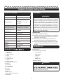
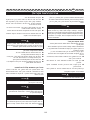
PACKING LIST
Dethatcher
Accessory bag (includes)
• cord retainer
• knob & bolt
• cable clip
• screws
• Battery key
User's Manual
WARNING
Do not attempt to modify this product or create ac-
cessories not recommended for use with this prod-
and could result in a hazardous condition leading to
possible serious personal injury.
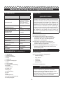
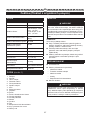
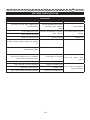
SPECIFICATIONS
Model 2504807
Voltage 40V
Vibration level
Right handle 4.293 m/s².
1,5 m/s²
Left handle 3.121 m/s²
1,5 m/s²
Sound pressure level 76.1 dB(A), k=3.0 dB(A)
Sound power level 89.6 dB(A), k=3.0 dB(A)
Guaranteed sound
power level 93 dB(A)
Speed 3,
600 RPM
Dethatching Path 14” (36 cm)
Dethatching depth 3/8” (1 cm)
Wheel size 7” (17.8 cm)
Weight (without
battery) 10.2 kg
Battery 29717/29727
Charger 2910907
DESCRIPTION
1. Handle bar
2. Bale lever
3. Upper handle
4. Knob
5. Cable clip
6. Lower handle
7. Wheel
8. Electrical cord
9. Safety lock-out button
10. Screw
11. Hex bolt
12. Flat washer
13. Lock washer
14. Lock
15. Spring
16. Pin
17. Battery key
18. Rear discharge opening
19. Grassbox

English (Original instructions)
EN
DE ES IT FR PT NL RU FI SV NO DA PL CS SK SV HR HU RO BG EL AR TR HE LT LV ET
3
WARNING
Stop the machine, and remove battery pack.
Make sure that all moving parts have come to a
complete stop. Failure to comply could result in ac-
cidental starting and possible serious personal injury.
WARNING
If any parts are damaged or missing do not operate
this product until the parts are replaced. Using a
product with damaged or missing parts could result
in serious personal injury.
INSTALLING THE LOWER HANDLE(See figure 2)
Insert the lower handle (6) into the housing hole.
lower handle to the housing using a star-head
screwdriver (not supplied).
INSTALLING THE UPPER HANDLE(See figure 2)
Position the upper handle so the holes line up with
the lower handle holes.
Insert the supplied hex bolt (11) through the hole
from the outside of the handlebar.
Thread the knob (4) onto the hex bolt (11) to
tighten securely into place.
INSTALLING THE GRASSBOX (See figure 3)
Lift the rear discharge door.
Lift the grassbox by its handle and place under the
are seated into the slots in the handle bracket.
the hooks on the grassbox will rest securely in the
slots on the handle brackets.
OPERATION
WARNING
Do not allow familiarity with products to make you
careless. Remember that a careless fraction of a
WARNING
Always wear eye protection. Failure to do so could
result in objects being thrown into your eyes resulting
in possible serious injury.
WARNING
destroy plastic which may result in serious personal inju-
ry. Only the parts shown on the parts list are intended to
be repaired or replaced by the customer. All other parts
should be replaced at an Authorized service center.
BATTERY REMOVAL (See figure 4)
Release the bale lever to stop the product.
Open the battery door to access the battery
compartment.
Remove the battery key.
Press in and hold the battery release button with
firm grip.
Remove battery pack from the product.
BATTERY INSTALLATION(See figure 4)
Lift and hold up the battery door.
Align the battery with the dethatcher’s battery port.
Make sure the battery release button snaps in
place and that battery is fully seated and secure in
the dethatcher before beginning operation.
Insert the battery key.
do not insert the battery key.
Close the door.
STARTING THE DETHATCHER
Press and hold the safety lock-out button. This
makes the bale switch operational.
Press the bale switch against to the handlebar to
operate.
STOPPING THE DETHATCHER
Release the bale.
MAINTENANCE
The dethatcher cylinder can cause injuries! Prior
the dethatcher cylinder has stopped. Wear heavy-
duty work gloves when making adjustments. If the
dethatcher cylinder is not yet worn but individual
identical replacement springs may be used.

English (Original instructions)
EN
DE ES IT FR PT NL RU FI SV NO DA PL CS SK SV HR HU RO BG EL AR TR HE LT LV ET
4
Replace the tine into position and slide the pin
back into place pressing the pin against a solid
surface to pressure it back into place.
DANGER! THE DETHATCHER CYLINDER
CAN CAUSE INJURIES.
battery pack and wait until the dethatcher cylinder has
stopped. Wear heavy-duty gloves for performing main-
tenance. The lawn dethatcher should be cleaned after
each use.
WARNING
-
PLACEMENT PARTS. USE OF ANY OTHER PARTS
MAY CREATE A HAZARD OR CAUSE PRODUCT
DAMAGE.
WARNING
GOGGLES OR SAFETY GLASSES AT ALL TIMES
WHEN OPERATING THIS UNIT. WEAR A FACE
MASK OR DUST MASK IN DUSTY LOCATIONS.
WARNING
-
FROM POWER SOURCE AND WAIT FOR ALL
MOVING PARTS TO STOP. FAILURE TO FOLLOW
THESE INSTRUCTIONS CAN RESULT IN SERIOUS
PERSONAL INJURY OR PROPERTY DAMAGE.
Avoid using solvents when cleaning plastic parts. Most
plastics are susceptible to damage fromvarious types of
commercial solvents and may be damaged by their use.
WARNING
-
-
RESULT IN SERIOUS PERSONAL INJURY. ONLY
THE PARTS SHOWN ON THE PARTS LIST ARE IN-
TENDED TO BE REPAIRED OR REPLACED BY THE
CUSTOMER. ALL OTHER PARTS SHOULD BE RE-
PLACED AT ANAUTHORIZED SERVICE CENTER.
WARNING
-
and wait until the dethatcher cylinder has stopped.
Failure to follow these instructions can result in seri-
ous personal injury or property damage.
WARNING
carrying out any maintenance.
REPLACING THE TINES (See figure 5 )
WARNING
off and remove the battery pack before performing
any maintenance.
Use only the manufacturer's original replacement parts.
sufficient time for moving parts to totally stop.
Turn the dethatcher over.
flat washer (13) and the lock washer (14) which
secure the tine casing. Remove the two nuts on the
opposite side with a star-head screwdriver.
Press the lock (15) on the edge of the shaft with a
slotted screwdriver to separate the tine casing from
the shaft.
Replace the worn or broken tines with new ones.
Fasten the tine casing back together using the flat
washer and the lock washer in their original order.
WARNING
All the screws to mount the halves of the tine holder
on their threads to prevent screws from loosening
during usage.
REPLACING THE TINES
Remove the tine cartridge as demonstrated on
Secure tine cartridge on a workbench.
Push out the pin using a screwdriver (Not Sup-
plied). This may require the use of a rubber mallet
if more strength is required.
Remove and discard the worn/broken tines.

English (Original instructions)
EN
DE ES IT FR PT NL RU FI SV NO DA PL CS SK SV HR HU RO BG EL AR TR HE LT LV ET
5
RISK OF INJURY AND PHYSICAL DAMAGE!
Do not clean the lawn dethatcher under running water
(particularly under high pressure).
Do not use hard or pointed objects for cleaning the
lawn dethatcher.
for storage by releasing the knobs.
does not become trapped. Store the lawn dethatcher
Turn the it off and remove the battery pack and wait
until the dethatcher cylinder has stopped.
Always clean the bottom of the dethatcher after
each use and before storage.
Carefully inspect all tines and cartridges for damage
and replace when required.
This device must not be disposed of with normal
household waste. It must bedisposed of in accordance
with local regulations.
DANGER!
The dethatcher cylinder can cause injuries.

English (Original instructions)
EN
DE ES IT FR PT NL RU FI SV NO DA PL CS SK SV HR HU RO BG EL AR TR HE LT LV ET
6
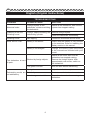
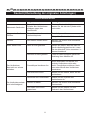
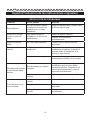
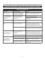
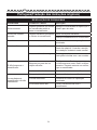
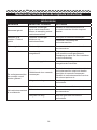
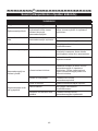
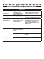
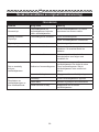
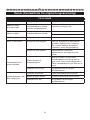
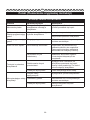
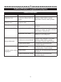
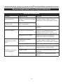
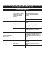
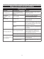
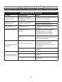
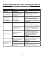
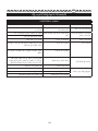
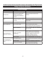
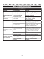
TROUBLESHOOTING
PROBLEM POSSIBLE CAUSE SOLUTION
Abnormal noise.
Foreign objects on the
dethatcher cylinder are hitting
the dethatcher.
cylinder has stopped rotating.
Clattering in the unit.
Whistling sound.
Foreign objects blocking the
dethatching cylinder.
Remove foreign objects.
Check the dethatcher immediately.
Whistling sound. Belt slipping. Contact an authorized service centre.
Motor will not s tart. Battery is not secure. Ensure that the battery is fully secured
in the machine. Refer to Installing the
Battery section in this manual.
Battery is not charged. Charge the battery pack according
to the instructions included with your
model.
The dethatcher is hard
to push.
Blocked by foreign objects.
dethatcher has stopped rotating.
Remove the foreign objects. After
the dethatcher.
The grass is too tall. Mow the lawn before dethatching.
Dethatching results are
not satisfactory.
Spring tine wear. Adjust the dethatcher cylinder.
Belt faulty. Contact an authorized service centre.
Lawn has grown too tall. Mow the lawn before using the
dethatcher.

Deutsch(Übersetzung der originalen Anleitungen)
7
EN
DE
ES IT FR PT NL RU FI SV NO DA PL CS SK SL HR HU RO BG EL AR TR HE LT LV ET
MONTAGE
WARNUNG
Dieses neue Produkt wurde teilweise montiert in
dem unten beschriebenen Zustand verschickt.
Prüfen Sie sorgfältig die nachfolgende Packliste, um
sicherzustellen, dass alle Elemente in der Verpack-
ung enthalten sind. Die Packliste führt alle losen El-
emente auf, die bei Versand nicht am Produkt mon-
tiert sind.Verwenden Sie dieses Produkt nicht, wenn
beim Auspacken auf der Packliste aufgeführte Teile
bereits an Ihr Produkt montiert sind. Rufen Sie die
unten stehende Kundendienst-Rufnummer an, um
Hilfe zu erhalten. Die Benutzung eines Produktes,
das möglicherweise falsch vormontiert wurde, kann
zu schweren Verletzungen führen.
AUSPACKEN
Dieses Produkt muss vor der ersten Benutzung
zusammengebaut werden.
Retire con cuidado el producto y los accesorios de
la caja. Asegúrese de que están incluidos todos
los elementos que figuran en la lista del paquete
de embalaje.
Inspeccione cuidadosamente el producto para
asegurarse de que hubo ninguna rotura o daño
durante el transporte.
No deseche el material del envase hasta que haya
inspeccionado cuidadosamente y haya utilizado
satisfactoriamente el producto.
PACKLISTE
Vertikutierer
Zubehörbeutel (enthält)
• Kabelhalterung
• Drehknauf und Bolzen
• Kabelklemme
• Schrauben
• Akkuschlüssel
Bedienungsanleitung
TECHNISCHE DATEN
Modell 2504807
Voltzahl 40V
Vibration
Rechter Griff 4.293
m/s². 1,5 m/s²
Linker Griff 3.121
m/s² 1,5 m/s²
Gemessener
Schalldruckpegel
76.1 dB(A), k=3.0
dB(A)
Gemessener
Schallleistungspegel
Garantierter
Schallleistungspegel
Drehzahl 3,
600 RPM
Vertikutierbreite 14” (36 cm)
Vertikutiertiefe 3/8” (1 cm)
Radgröße 7” (17.8 cm)
Gewicht (Akku nicht im
Lie ferumfang enthalten) 10.2 kg
Akku 29717/29727
ladegerät 2910907
BAUTEILE(Siehe Abbildung 1.)
1. Schubbügel
2. Bügelschalter
3. Oberer Griffbügel
4. Knopf
5. Kabelschelle
6. Unterer Handgriff
7. Rad
8. Netzkabel
9. Sicherungsknopf
10. Schraube
11. Sechskantschraube
12. Flache Unterlegscheibe
13. Sicherungsscheibe
14. Arretierung
15. Feder
16. Stift
17. Akkuschlüssel
18. Hintere Auswurföffnung
19. Knopf zur Höheneinstellung
89.6 dB(A),
k=3.0 dB(A)
93 dB(A)

Deutsch(Übersetzung der originalen Anleitungen)
8
EN
DE
ES IT FR PT NL RU FI SV NO DA PL CS SK SL HR HU RO BG EL AR TR HE LT LV ET
WARNUNG
nicht empfohlen ist. Sollten Sie während Wartung-
könnten dies schwere Personen- und Sachschäden
mit sich bringen.
WARNUNG
Schalten Sie das Gerät aus und entfernen Sie den
vollständig still stehen. Andernfalls könnte das Gerät
unabsichtlich gestartet werden und möglicherweise
schwere Verletzungen verursachen.
WARNUNG
Falls Teile fehlen oder beschädigt sind sollte das
Gerät nicht in Betrieb genommen werden bevor
alles korrekt ersetzt wurde. Die Verwendung eines
Produkts mit beschädigten oder fehlenden Teilen
kann zu schweren Verletzungen führen.
MONTAGE DES UNTEREN BÜGELS (Siehe
Abbildung 2)
Stecken Sie den unteren Bügel (6) in das Loch im
Gehäuse.
Befestigen Sie den unteren Bügel mit den
mitgelieferten Schrauben (10) und mithilfe eines
Schraubendrehers (nicht inbegriffen) am Gehäuse.
DIE INSTALLATION DES OBEREN
GRIFFS(Siehe Abbildung 2)
Löcher auf die des unteren Bügels ausgerichtet
sind.
Stecken Sie die Sechskantschraube (11) von der
Außenseite des Schubbügels durch das Loch.
Schrauben Sie den Schraubknopf (4) auf die
Position zu fixieren.
MONTAGE DES GRASFANGKORBES (Siehe
Abbildung 3)
Öffnen Sie die hintere Klappe zum Entleeren.
Heben Sie den Grasfangkorb am Handgriff an und
Haken an dem Grasfangkorb in den Schlitzen des
Griffbügels sitzen.
Lösen Sie die hintere Klappe. Bei richtiger
Montage sitzen die Haken des Grasfangkorbs
sicher in den Schlitzen an dem Griffbügel.
VERWENDUNG
WARNUNG
mit Ihrem Gerät vertraut gemacht haben. Denken
-
verursachen.
WARNUNG
Tragen Sie immer einen Augenschutz. Die Missa-
Fremdkörper in Ihre Augen spritzen und schwere
Augenverletzungen verursachen.
WARNUNG
-
tikteilen in kontakt geraten. Chemikalien können
was zu schweren verletzungen führen kann. Nur die
in der Teileliste aufgeführten Teile sind dazu bestim-
Alle anderen Teile sollten von einem autorisierten
Servicecenter ersetzt werden.
ENTNEHMEN DES AKKUS (Siehe Abbildung
4)
Zum Anhalten des Produkts lassen Sie den
Bügelhebel los.
dem Akkufach zu bekommen.
Entfernen Sie die Akkusicherung.
Drücken Sie die Entriegelungstaste der Batterie ein
und halten Sie sie fest.
Akku aus dem Produkt entfernen.
EINSETZEN DES AKKUS(Siehe Abbildung 4)
Heben Sie die Akkuabdeckung an und halten sie
hoch.
Richten Sie den Akku am Akkuanschluss des
Vertikutierers aus.
die Entriegelungstaste des Akkus einrastet
und dass der Akku vollständig und sicher im
Vertikutierer sitzt.

Deutsch(Übersetzung der originalen Anleitungen)
9
EN
DE
ES IT FR PT NL RU FI SV NO DA PL CS SK SL HR HU RO BG EL AR TR HE LT LV ET
Stecken Sie den Akkuschlüssel ein.
Wenn die Maschine nicht sofort benutzt werden
Schließen Sie die Klappe.
STARTEN DES VERTIKUTIERERS
Drücken und halten Sie die Auslösesperre.
Dadurch wird der Bügelschalter aktiviert.
Drücken Sie den Bügelschalter an den
AUSSCHALTEN DES VERTIKUTIERERS
Lassen Sie den Bügelschalter los.
WARTUNG UND PFLEGE
Die Walze des Vertikutierers kann Verletzungen
verursachen! Ziehen Sie den Stecker des Gerätes
wenn Sie Einstellungen am Gerät vornehmen. Wenn
die Walze des Vertikutierers noch nicht abgenutzt
ausgewechselt werden. Es dürfen nur baugleiche
Ersatzzinken verwendet werden.
WARNUNG
-
steht. Nichtbeachtung dieser Anweisungen kann zu
schweren Körperverletzungen oder Sachschäden
führen.
WARNUNG
-
führen.
AUSWECHSELN DER ZINKEN (Siehe abbil-
dung 5.)
WARNUNG
bevor Sie Wartungsarbeiten durchführen.
Verwenden Sie nur vom Hersteller empfohlene Origi-
nalersatzteile.
Schalten Sie das Gerät aus und entfernen Sie
komplett stillstehen.
Drehen Sie den Vertikutierer um.
Ent
Unterlegscheibe (13) und die Sicherungsscheibe
die zwei Muttern auf der gegenüberliegenden Seite
mit einem Schraubendreher.
Drücken Sie die Arretierung (15) am Rand der
Zinkengehäuse von der Welle zu trennen.
Ersetzen Sie abgenutzte oder defekte Zinken durch
neue.
Bauen Sie das Zinkengehäuse mithilfe der flachen
Unterlegscheibe und der Sicherungsscheibe in ihrer
ursprünglichen Reihenfolge wieder zusammen.
WARNUNG
Unterlegscheiben (13) und Sicherungsscheiben
Schrauben sich während des Gebrauchs lösen.
AUSWECHSELN DER ZINKEN (Siehe abbildung 6)
6 gezeigt.
Fixieren Sie die Zinkenkassette auf einer Werk-
bank.
Schieben Sie den Stift (17) mitilfe eines
Schraubendrehers (nicht inbegriffen) heraus.
Eventuell müssen Sie einen Gummihammer zu
Entfernen und entsorgen Sie abgenutzte/defekte
Zinken.
Setzen Sie die neuen Zinken ein und schieben Sie
den Stift (17) wieder an seinen Platz. Drücken Sie
mit Nachdruck in Position zu schieben.
GEFAHR! DIE WALZE DES
VERTIKUTIERERS KANN VERLETZUNGEN
VERURSACHEN.
-
das Gerät warten. Der Rasenvertikutierer sollte nach

Deutsch(Übersetzung der originalen Anleitungen)
10
EN
DE
ES IT FR PT NL RU FI SV NO DA PL CS SK SL HR HU RO BG EL AR TR HE LT LV ET
jedem Gebrauch gereinigt werden.
WARNUNG
VERWENDEN SIE BEI DER WARTUNG NUR
IDENTISCHE ERSATZTEILE. DER EINSATZ VON
ANDEREN TEILEN KANN EINE GEFAHR VERUR-
SACHEN ODER DAS PRODUKT BESCHLÄGT.
WARNUNG
WENN SIE DIESES GERÄT BENUTZEN TRAGEN
SIE IN STAUBIGER UMGEBUNG EINE GESICHTS-
ODER STAUBMASKE.
WARNUNG
UND ZIEHEN SIE DEN NETZSTECKER BEVOR
ODER WARTEN. NICHTBEACHTUNG DIESER
ANWEISUNGEN KANN ZU SCHWEREN KÖRPER-
VERLETZUNGEN ODER SACHSCHÄDEN FÜH-
REN.
Verwenden Sie keine Lösemittel zum Reinigen der
Kunststoffteile. Die meisten Kunststoffe können durch
im Handel erhältliche Lösemittel beschädigt werden.
Verwenden Sie einen sauberen Lappen für die Entfer-
WARNUNG
-
USW. MIT DEN PLASTIKTEILEN IN KONTAKT GER-
ATEN. CHEMIKALIEN KÖNNEN PLASTIK BESCHÄ-
ZU SCHWEREN VERLETZUNGEN FÜHREN KANN.
NUR DIE IN DER TEILELISTE AUFGEFÜHRTEN
-
PARIERT ODER AUSGEWECHSELT ZU WERDEN.
ALLE ANDEREN TEILE SOLLTEN VON EINEM AUTO-
RISIERTEN SERVICECENTER AUSGEWECHSELT
WERDEN.
GEFAHR VON VERLETZUNGEN UND
SACHSCHÄDEN!
Reinigen Sie den Rasenvertikutierer nicht unter
laufendem Wasser (insbesondere unter hohem Was-
serdruck).
Benutzen Sie keine harten oder spitzen Objekte zum
Reinigen des Rasenvertikutierers.
Der Rasenvertikutierer kann zum Aufbewahren zusam-
hierzu die Schraubknöpfe.
-
bel nicht eingeklemmt wird. Bewahren Sie den Rasen-
für Kinder unzugänglich auf.
Vertikutierers nicht mehr bewegt.
Reinigen Sie nach jedem Gebrauch und vor der
Lagerung immer die Unterseite des Vertikutierers.
Untersuchen Sie sorgfältig alle Zinken und
Kassetten auf Beschädigungen und ersetzen Sie
Dieses Gerät darf nicht mit den normalen Hausabfäl-
len entsorgt werden. Es muss unter Einhaltung der
regionalen Vorschriften entsorgt werden.
GEFAHR
Die Walze des Vertikutierers kann Verletzungen
verursachen.

Deutsch(Übersetzung der originalen Anleitungen)
11
EN
DE
ES IT FR PT NL RU FI SV NO DA PL CS SK SL HR HU RO BG EL AR TR HE LT LV ET
FEHLERBEHEBUNG
Problem Möglicher Grund Lösung
Abnormale Geräusche
Fremdkörper auf dem
Zylinder des Vertikutierers
schlagen gegen den
Vertikutierer.
Schalten Sie den Vertikutierer aus und
mehr dreht.
Klappern im Gerät.
Pfeifton.
Fremdkörper blockieren den
Vertikutierzylinder.
Fremdkörper entfernen.
Überprüfen Sie den Vertikutierer sofort.
Pfeifton. Der Riemen rutscht durch. Wenden Sie sich an eine autorisierte
Servicestelle.
Motor startet nicht. Akku ist nicht gesichert.
Gerät vollständig gesichert ist. Lesen
Sie den Abschnitt „Akku einsetzten“ in
diesem Handbuch.
Der Akku ist nicht geladen. Laden Sie das Akkupack gemäß der
Anleitung Ihres Modells auf.
Der Vertikutierer
lässt sich nur schwer
schieben.
Fremdkörper blockieren ihn.
sich der Vertikutierer nicht mehr
dreht. Fremdkörper entfernen. Nach
etwa einer Minute den Vertikutierer
einschalten.
Das Gras ist zu hoch.
vertikutieren.
Die Vertikutierresultate
sind unbefriedigend.
Verschleiß des Federzinken. Stellen Sie den Zylinder des
Vertikutierers ein.
Riemen ist defekt. Wenden Sie sich an eine autorisierte
Servicestelle.
Der Rasen ist zu hoch
gewachsen.
Mähen Sie den Rasen vor dem
Gebrauch des Vertikutierers.

Español(Traducción de las instrucciones originales)
12
EN DE
ES
IT FR PT NL RU FI SV NO DA PL CS SK SL HR HU RO BG EL AR TR HE LT LV ET
19. Caja de la hierba
MONTAJE
AVISO
Este nuevo producto ha sido transportado con un
montaje parcial, como se describe a continuación.
Examine detenidamente la lista de contenido in-
cluida a continuación para asegurarse de que to-
dos los elementos indicados estén presentes en el
embalaje. La lista de embalaje describe todos los
elementos sueltos no ensamblados en el producto
a su salida de fábrica.No utilice este producto si ya
está montado en el producto algún elemento de la
lista del paquete de embalaje cuando lo desembale.
Llame al número del departamento de atención al
cliente indicado a continuación si necesita asistencia
al respecto. La utilización de un producto que su-
puestamente haya sido preensamblado de manera
incorrecta podría dar lugar a lesiones físicas graves.
DESEMBALAJE
Es necesario montar este producto.
Retire con cuidado el producto y los accesorios de
la caja. Asegúrese de que están incluidos todos
los elementos que figuran en la lista del paquete
de embalaje.
Inspeccione cuidadosamente el producto para
asegurarse de que hubo ninguna rotura o daño
durante el transporte.
No deseche el material del envase hasta que haya
inspeccionado cuidadosamente y haya utilizado
satisfactoriamente el producto.
LISTA DE PIEZAS
Escarificador
Bolsa de accesorios que incluye lo siguiente:
• Sujeción para cable de alimentación
• Perilla y tornillo
• Clip del cable
• Tornillos
• Llave de la batería.
Manual de utilización
ESPECIFICACIONES
Modelo 2504807
Voltaje 40V
Vibration level
Mango derecho
4.293 m/s². 1,5 m/s²
Mango izquierdo
3.121 m/s² 1,5 m/s²
Nivel de presión sonora 76.1 dB(A), k=3.0
dB(A)
Nivel de potencia acústica
Nivel de potencia acústica
garantizado
Velocidad 3,
600 RPM
14” (36 cm)
Profundidad de 3/8” (1 cm)
Tamaño de las ruedas 7” (17.8 cm)
Gewicht (batería no
incluida) 10.2 kg
Batería 29717/29727
Cargador de pilas 2910907
DESCRIPTION
1. Manillar
2. Bale lever
3. Asa superior
4. Botón
5. Grapa de sujeción del cable
6. Baje el mango
7. Rueda
8. Cable de alimentación
9. Botón de desbloqueo de seguridad
10. Tornillo
11. Tornillo hexagonal
12. Arandela plana
13. Arandela de bloqueo
14. Seguro
15. Muelle
16. Pasador
17. Llave de la batería
18. Apertura trasera de descarga
93 dB(A)
89.6 dB(A), k=3.0 dB(A)

Español(Traducción de las instrucciones originales)
13
EN DE
ES
IT FR PT NL RU FI SV NO DA PL CS SK SL HR HU RO BG EL AR TR HE LT LV ET
AVISO
No intente modi car este producto o crear acceso-
rios que no fueron recomendados para usar con este
considerará como mal uso y podrá resultar en una
-
nes personales serias.
AVISO
Detenga la máquina y retire la batería. Asegúrese
de que todas las piezas móviles se hayan deteni-
do por completo. De no observarse esta instruc-
manera fortuita y provocar lesiones físicas graves.
AVISO
utilice este producto hasta que se hayan reem-
plazado las piezas. El uso de un producto al que le
producir lesiones personales graves.
INSTALACIÓN DE LA SECCIÓN INFERIOR
DEL MANILLAR (consulte la figura 2)
orificios previstos a tal efecto en la carcasa.
sirviéndose de un destornillador de estrella (no
suministrado).
INSTALACIÓN DE LA CAJA DE LA
HIERBA(consulte la figura 2)
manera que sus orificios queden alineados con los
Inserte el tornillo hexagonal suministrado (11)
a través del orificio desde el lado exterior del
manillar.
Rosque la perilla (4) en el tornillo hexagonal (12) y
apriétela para sujetar el manillar en su sitio.
INSTALACIÓN DE LA CAJA DE LA
HIERBA(consulte la figura 3)
Levante la puerta de descarga trasera.
Levante el colector de césped sujetándolo por el
descarga para que los ganchos del colector de
césped queden asentados en la barra de la puerta.
Suelte la puerta trasera de descarga. Cuando se
césped se extienden a través de las aberturas de
la puerta de descarga trasera.
FUNCIONAMIENTO
AVISO
Aun cuando esté familiarizado con el aparato no
deje de estar atento. No olvide nunca que basta con
AVISO
-
pos extraños a sus ojos y provocarle graves lesiones
oculares.
AVISO
No permita en ningún momento que las piezas de
-
ede ocasionar graves daños personales. Tan solo
aquellos elementos que se incluyen en la lista de
despiece podrán ser reparados o sustituidos por el
usuario. Cualquier otro elemento deberá sustituirlo
un Servicio Técnico Autorizado.
EXTRAER LA BATERÍA (consulte la figura 4)
Suelte la palanca de accionamiento para detener
el producto.
Abra la compuerta de la batería para tener acceso
a la batería.
Retire la llave de la batería.
batería con firmeza.
Saque la batería del producto.
INSTALAR LA BATERÍA(consulte la figura 4)
Levante y mantenga la cubierta de la batería
abierta.
Alinee la batería con el compartimento de la
batería del escarificador.
batería encaje su lugar y que la batería esté bien
instalada y asegurada en el escarificador antes de
iniciar cualquier trabajo.

Español(Traducción de las instrucciones originales)
14
EN DE
ES
IT FR PT NL RU FI SV NO DA PL CS SK SL HR HU RO BG EL AR TR HE LT LV ET
Inserte la llave de la batería.
no inserte la llave de la batería.
Cierre la puerta.
PUESTA EN MARCHA DEL ESCARIFICADOR
Abra la puerta del compartimiento de la batería.
operativa.
superior del manillar para poner en marcha la
herramienta.
APAGADO DEL ESCARIFICADOR
MANTENIMIENTO
¡El tambor del escarificador puede suponer un riesgo
de lesiones! Antes de efectuar cualquier ajuste en la
a que el tambor del escarificador se haya detenido por
completo. Utilice guantes de trabajo resistentes a la
hora de efectuar cualquier ajuste en la herramienta. Si
el tambor del escarificador aún no presenta desgaste
podrán sustituirse por otros idénticos.
AVISO
batería y espere a que el cilindro se haya detenido.
El incumplimiento de estas instrucciones puede re-
sultar en lesiones corporales graves o daños a la
propiedad.
AVISO
seguridad antes de proceder a efectuar cualquier
SUSTITUCIÓN DE LAS PÚAS (consulte la
figura 5 )
AVISO
y saque la batería antes de realizar cualquier tarea
de mantenimiento.
Utilice únicamente piezas de repuesto originales del
fabricante.
Detenga la máquina y retire la batería. Espere lo
de la herramienta se hayan detenido por completo.
Voltee el escarificador.
arandela plana (13) y la arandela de bloqueo (14)
que fijan la carcasa de las púas a la herramienta.
Utilice un destornillador de estrella para retirar las
dos tuercas presentes en el lado opuesto.
Utilice un destornillador plano para presionar el
seguro (15) presente en el borde del eje y poder así
separar de este la carcasa de púas.
Sustituya las púas desgastadas o rotas por otras
nuevas.
Vuelva a fijar la carcasa de púas en la herramienta
colocando la arandela plana y la arandela de
seguridad en sus respectivas posiciones originales.
AVISO
-
miento de las púas deberán contar con una arandela
plana (13) y una arandela de bloqueo (14) para evi-
-
ramienta.
SUSTITUCIÓN DE LAS PÚAS(consulte la
figura 6)
Desmonte el cartucho de púas según se muestra
púas en un banco de trabajo.
Utilice un destornillador (no suministrado) para
empujar el pasador y extraerlo de su sitio. Podrá
necesitar utilizar un mazo de goma en caso de que
el pasador ofrezca mayor resistencia de lo normal.
Retire y deseche las púas desgastadas o rotas.
Coloque las nuevas púas en su sitio y vuelva a
totalmente encajado en su sitio.
¡PELIGRO! EL TAMBOR DEL
ESCARIFICADOR PUEDE SUPONER UN
RIESGO DE LESIONES.
que el cilindro se haya detenido.Utilice guantes resis-

Español(Traducción de las instrucciones originales)
15
EN DE
ES
IT FR PT NL RU FI SV NO DA PL CS SK SL HR HU RO BG EL AR TR HE LT LV ET
tentes para llevar a cabo el mantenimiento. Deberá
uso.
AVISO
UTILICE SOLO RECAMBIOS ORIGINALES AL AR-
REGLAR LA MÁQUINA. EL USO DE OTRAS PIE-
ZAS PUEDE PROVOCAR RIESGOS O DAÑOS EN
EL PRODUCTO.
AVISO
PORTEZ DES LUNETTES DE SÉCURITÉ EN
TOUT TEMPS LORSQUE VOUS UTILISEZ CETTE
SOUFFLEUSE. PORTEZ UN ÉCRAN FACIAL OU
UN MASQUE ANTIPOUSSIÈRE DANS LES EN-
DROITS POUSSIÉREUX.
AVISO
-
-
PERE A QUE TODAS LAS PIEZAS MÓVILES SE
DETENGAN Y DESCONECTE EL ENCHUFE DE LA
TOMA DE CORRIENTE. EL INCUMPLIMIENTO DE
ESTAS INSTRUCCIONES PUEDE RESULTAR EN
LESIONES CORPORALES GRAVES O DAÑOS A
LA PROPIEDAD.
No utilice disolventes para limpiar las piezas de
plástico. La mayor parte de los plásticos pueden
resultar dañados con los disolventes que se venden
en el comercio.Utilice un paño limpio para retirar las
AVISO
NO PERMITA EN NINGÚN MOMENTO QUE LAS PIE-
ZAS DE PLÁSTICO ENTREN EN CONTACTO CON
-
QUE PUEDE OCASIONAR GRAVES DAÑOS PERSO-
NALES. TAN SOLO AQUELLOS ELEMENTOS QUE SE
INCLUYEN EN LA LISTA DE DESPIECE PODRÁN SER
REPARADOS O SUSTITUIDOS POR EL USUARIO.
CUALQUIER OTRO ELEMENTO DEBERÁ SUSTITU-
IRLO UN SERVICIO TÉCNICO AUTORIZADO.
¡RIESGO DE LESIONES FÍSICAS Y DAÑOS
MATERIALES EN LA HERRAMIENTA!
No utilice objetos duros o puntiagudos para limpiar su
-
dor para césped.
al que niños no puedan acceder.
a que el cilindro se haya detenido.
Asegúrese siempre de limpiar la parte inferior del
escarificador después de cada uso y antes de
proceder a guardarlo.
Examine minuciosamente todas las púas y
cartuchos por si presentasen daños y sustitúyalos
de ser necesario.
Esta herramienta no deberá desecharse junto con los
desecharse conforme a lo establecido por las norma-
tivas locales.
¡PELIGRO!
riesgo de lesiones.

Español(Traducción de las instrucciones originales)
16
EN DE
ES
IT FR PT NL RU FI SV NO DA PL CS SK SL HR HU RO BG EL AR TR HE LT LV ET
RESOLUCIÓN DE PROBLEMAS
Problema Causa posible Solución
Se han introduzco objetos
extraños en el cilindro del
golpeando.
el cilindro deje de girar.
Ruidos en la unidad.
Sonido a modo de
pitido.
Hay objetos extraños
bloqueando el cilindro del
Retire los objetos extraños.
inmediatamente.
Sonido a modo de
pitido.
La correa está patinando. Contacte con un servicio técnico
autorizado.
El motor no se pone en
marcha.
La batería no está bien
asegurada.
Asegúrese de que la batería está bien
instalada en la máquina. Consulte el
batería en este manual.
La batería no está cargada. Cargue la batería siguiendo las
instrucciones incluidas con su modelo.
delante.
Está bloqueado por objetos
extraños.
Apague el motor y espere a que el
los objetos extraños. Después de un
La hierba está demasiado
crecida.
buen resultado.
Desgaste de la púa de
resorte.
Fallo de la correa. Contacte con un servicio técnico
autorizado.
El césped está demasiado
crecido.
Corte el césped antes de usar el

Italiano(Traduzione dalle istruzioni originali)
17
EN DE ES
IT
FR PT NL RU FI SV NO DA PL CS SK SL HR HU RO BG EL AR TR HE LT LV ET
MONTAGGIO
AVVERTENZA
Questo prodotto viene venduto parzialmente mon-
tato nelle condizioni indicate di seguito.Controllare
accuratamente che nella confezione siano inclusi
tutti gli elementi elencati alla sezione Contenuto
della confezione; l'elenco descrive tutti i singoli el-
ementi non pre-assemblati.Non utilizzare il prodotto
se le parti sulla lista involucro sono già state montate
sul prodotto. Contattare il servizio clienti per ricevere
assistenza. L'uso di un prodotto pre-assemblato in
modo scorretto comporta il rischio di lesioni gravi.
RIMOZIONE IMBALLO
Questo prodotto deve essere montato.
Rimuovere attentamente il prodotto e i suoi
accessori dalla scatola. Assicurarsi che tutte le
parti indicate nell'apposita lista siano incluse.
Ispezionare il prodotto attentamente per assicurarsi
che non si siano verificati danni o rotture durante le
operazioni di trasporto.
Non smaltire il materiale dell'imballo fino a che il
prodotto non sia stato attentamente ispezionato e
messo in funzione.
LISTA PARTI
Scarificatore
Sacchetto degli accessori (include)
• fermacavo
• manopola e bullone
• Serracavo
• viti
• Chiave batteria
Manuale d’uso
AVVERTENZA
Non tentare di modif icare questo utensile o di creare
accessori non raccomandati per l’utilizzo con questo
prodotto. Tali modif iche equivalgono a un utilizzo
non consentito e possono causare situazioni perico-
lose in grado di provocare gravi lesioni f i siche.
SPECIFICHE
Modello 2504807
Voltaggio 40V
livello di vibrazioni
Manico destro 4.293
m/s². 1,5 m/s²
Manico sinistro 3.121
m/s² 1,5 m/s²
Livello di pressione
acustica misurato
76.1 dB(A), k=3.0
dB(A)
Livello di pressione
acustica garantito
Livello di potenza acustica
garantito
Velocità 3,
600 RPM
14” (36 cm)
3/8” (1 cm)
Dimensione ruota 7” (17.8 cm)
Peso (batteria non inclusa) 10.2 kg
Batteria 29717/29727
Caricatore 2910907
DESCRIPTION (Vedere Figura 1)
1. Impugnatura
2. Barra di avviamento
3. Manico superiore
4. Manopola
5. Fermacavo
6. Abbassare il manico
7. Ruota
8. Cavo di alimentazione
9. Pulsante di sbloccaggio di sicurezza
10. Vite
11. Dado esagonale
12. Rondella piatta
13. Rondella elastica
14. Blocco
15. Molla
16. Perno
17. Chiave batteria
18. Aperetura posteriore scarico
19. Scatola di raccolta erba
89.6 dB(A), k=3.0 dB(A)
93 dB(A)

Italiano(Traduzione dalle istruzioni originali)
18
EN DE ES
IT
FR PT NL RU FI SV NO DA PL CS SK SL HR HU RO BG EL AR TR HE LT LV ET
AVVERTENZA
l'assemblaggio non è terminato per evitare l'avvio
accidentale e il rischio di lesioni gravi.
AVVERTENZA
Nel caso in cui un componente manchi o sia
prima di averlo sostituito. L'utilizzo di un prodotto
con parti danneggiate o mancanti potrà causare
gravi lesioni personali.
INSTALLAZIONE DEL MANUBRIO
INFERIORE(Vedere Figura 2)
Inserire il manubrio inferiore (6) nel foro sull'unità
principale.
sull'unità principale usando un cacciavite a croce
(non fornito).
INSTALLAZIONE DEL MANICO
SUPERIORE(Vedere Figura 2)
Posizionare il manubrio superiore in modo tale che
i fori siano allineati con i fori sul manubrio inferiore.
Inserire il dado esagonale (11) fornito nel foro
dall'esterno del manubrio.
Avvitare la manopola (4) sul bullone esagonale
(11) e fissarla saldamente.
MONTAGGIO SCATOLA DI RACCOLTA
ERBA(Vedere Figura 3)
Alzare lo sportello di scarico posteriore.
Alzare il sacchetto raccoglierba dal manico e
posizionarlo sotto lo sportello di scarico posteriore
in modo che i ganci sul sacchetto di raccolta siano
correttamente agganciati sull'asta dello sportello.
Rilasciare la porta di scarico posteriore. Se
installati correttamente i ganci sul sacchetto
raccoglierba si estenderanno attraverso le aperture
nello sportello di scarico posteriore.
FUNZIONAMENTO
AVVERTENZA
dimestichezza con l'apparecchio. Non dimenticare
mai che basta un secondo di distrazione per ferirsi
in modo grave.
AVVERTENZA
Indossare sempre occhiali di protezione. La mancata
oculari.
AVVERTENZA
contatto con parti in plastica. Le sostanze chimiche po-
il che potrà risultare in gravi lesioni personali.Solo le parti
incluse nell'elenco delle parti possono essere riparate o
sostituite dall'operatore. Tutte le altre parti devono es-
sere sostituite da un centro di assistenza autorizzato.
PER RIMUOVERE IL GRUPPO BATTERIE
(Vedere Figura 4)
Rilasciare la barra di avanzamento per arrestare
l'apparecchio.
Aprire il vano di accesso al vano batteria.
Rimuovere la chiave della batteria.
Tenere saldamente premuto il pulsante di rilascio
della batteria.
Rimuovere la batteria dal prodotto.
PER INSTALLARE IL GRUPPO
BATTERIE(Vedere Figura 4)
Alzare e reggere il coperchio del vano batterie.
Allineare la batteria con la relativa presa
sull'apparecchio.
Assicurarsi che il pulsante di rilascio della
batteria scatti in posizione e che la batteria
sia completamente e saldamente inserita
nell'apparecchio prima dell'uso.
Inserire la chiave della batteria.
Se l’utensile non dovrà essere utilizzato
batteria.
Chiudere lo sportello.
AVVIAMENTO DELLO SCARIFICATORE
Premere e tenere premuto il tasto di sicurezza. Ciò
attiverà la barra di avviamento.
Premere la barra di avviamento contro
l'impugnatura per avviare lo scarificatore.
ARRESTO DELLO SCARIFICATORE
Rilasciare la barra di avviamento.

Italiano(Traduzione dalle istruzioni originali)
19
EN DE ES
IT
FR PT NL RU FI SV NO DA PL CS SK SL HR HU RO BG EL AR TR HE LT LV ET
MANUTENZIONE
Il rullo dello scarificatore può causare lesioni! Prima
scarificatore dalla rete elettrica e attendere che il
rullo si arresti. Indossare guanti robusti durante le
operazioni di regolazione. Se il rullo dello scarificatore
sostituirli. Utilizzare esclusivamente rebbi di ricambio
identici.
AVVERTENZA
-
cata osservanza di queste istruzioni potrà risultare in
gravi lesioni personali o danni alla proprietà.
AVVERTENZA
sicurezza prima di effettuare qualsiasi operazione di
manutenzione.
SOSTITUZIONE DEI REBBI (Vedere Figura 5)
AVVERTENZA
effettuare qualsiasi operazione di manutenzione.
Utilizzare esclusivamente parti di ricambio originali.
Arrestare l'apparecchio e rimuovere il gruppo
batteria. Attendere che le parti mobili si arrestino
completamente.
Capovolgere lo scarificatore.
(13) e la rondella elastica (14) che fissano il porta-
rebbio. Rimuovere i due dadi sul lato opposto con
un cacciavite a croce.
Premere il blocco (15) sul bordo del cilindro con un
cacciavite a taglio per separare il porta-rebbio dal
cilindro.
Sostituire i rebbi danneggiati o usurati con rebbi
nuovi.
Riposizionare il porta-rebbio usando la rondella
piatta e la rondella elastica nell'ordine originale.
AVVERTENZA
-
sere accompagnate da una rondella piatta (13) e
una rondella elastica (14) per evitare che si allentino
durante l'uso.
SOSTITUZIONE DEI REBBI(Figure 6)
Rimuovere la cartuccia come illustrato in Figura 6.
Conservare la cartuccia su un piano di lavoro.
Spingere il perno con un cacciavite (non fornito).
Per effettuare questa operazione potrebbe essere
necessario un martello in gomma.
Rimuovere e gettare i rebbi usurati/danneggiati.
Riposizionare il rebbio e reinserire il perno premen-
PERICOLO! IL RULLO DELLO
SCARIFICATORE PUÒ CAUSARE LESIONI!
rimuovere il gruppo batteria e attendere che il rullo
dello scarificatore si sia arrestato. Indossare guanti
robusti durante le operazioni di manutenzione. Pulire
AVVERTENZA
UTILIZZARE SOLO PARTI DI RICAMBIO IDEN-
TICHE. L’UTILIZZO DI PARTI DIVERSE POTRÀ
RAPPRESENTARE UN PERICOLO O CAUSARE
DANNI AL PRODOTTO.
AVVERTENZA
-
DOSSARE OCCHIALI O VISIERE DI PROTEZIONE
TUTTE LE VOLTE CHE SI METTE IN FUNZIONE
QUESTA UNITÀ. INDOSSARE UNA MASCHERA
PER IL VOLTO O PER LA POLVERE IN LUOGHI
POLVEROSI.
AVVERTENZA
PRIMA DI SVOLGERE LE OPERAZIONI DI PU-
LIZIA E RIPARAZIONE O DI CONTROLLARE
-
RARSI CHE TUTTE LE PARTI IN MOVIMENTO SI
SIANO FERMATE E SCOLLEGARE LA SPRINA
DALLA PRESA. LA MANCATA OSSERVANZA DI
QUESTE ISTRUZIONI POTRÀ RISULTARE IN
GRAVI LESIONI PERSONALI O DANNI ALLA PRO-
PRIETÀ.
Pagina se încarcă...
Pagina se încarcă...
Pagina se încarcă...
Pagina se încarcă...
Pagina se încarcă...
Pagina se încarcă...
Pagina se încarcă...
Pagina se încarcă...
Pagina se încarcă...
Pagina se încarcă...
Pagina se încarcă...
Pagina se încarcă...
Pagina se încarcă...
Pagina se încarcă...
Pagina se încarcă...
Pagina se încarcă...
Pagina se încarcă...
Pagina se încarcă...
Pagina se încarcă...
Pagina se încarcă...
Pagina se încarcă...
Pagina se încarcă...
Pagina se încarcă...
Pagina se încarcă...
Pagina se încarcă...
Pagina se încarcă...
Pagina se încarcă...
Pagina se încarcă...
Pagina se încarcă...
Pagina se încarcă...
Pagina se încarcă...
Pagina se încarcă...
Pagina se încarcă...
Pagina se încarcă...
Pagina se încarcă...
Pagina se încarcă...
Pagina se încarcă...
Pagina se încarcă...
Pagina se încarcă...
Pagina se încarcă...
Pagina se încarcă...
Pagina se încarcă...
Pagina se încarcă...
Pagina se încarcă...
Pagina se încarcă...
Pagina se încarcă...
Pagina se încarcă...
Pagina se încarcă...
Pagina se încarcă...
Pagina se încarcă...
Pagina se încarcă...
Pagina se încarcă...
Pagina se încarcă...
Pagina se încarcă...
Pagina se încarcă...
Pagina se încarcă...
Pagina se încarcă...
Pagina se încarcă...
Pagina se încarcă...
Pagina se încarcă...
Pagina se încarcă...
Pagina se încarcă...
Pagina se încarcă...
Pagina se încarcă...
Pagina se încarcă...
Pagina se încarcă...
Pagina se încarcă...
Pagina se încarcă...
Pagina se încarcă...
Pagina se încarcă...
Pagina se încarcă...
Pagina se încarcă...
Pagina se încarcă...
Pagina se încarcă...
Pagina se încarcă...
Pagina se încarcă...
Pagina se încarcă...
Pagina se încarcă...
Pagina se încarcă...
Pagina se încarcă...
Pagina se încarcă...
Pagina se încarcă...
Pagina se încarcă...
Pagina se încarcă...
Pagina se încarcă...
Pagina se încarcă...
Pagina se încarcă...
Pagina se încarcă...
Pagina se încarcă...
Pagina se încarcă...
Pagina se încarcă...
Pagina se încarcă...
Pagina se încarcă...
Pagina se încarcă...
Pagina se încarcă...
Pagina se încarcă...
Pagina se încarcă...
Pagina se încarcă...
Pagina se încarcă...
Pagina se încarcă...
Pagina se încarcă...
Pagina se încarcă...
Pagina se încarcă...
Pagina se încarcă...
Pagina se încarcă...
Pagina se încarcă...
Pagina se încarcă...
Pagina se încarcă...
Pagina se încarcă...
Pagina se încarcă...
Pagina se încarcă...
Pagina se încarcă...
Pagina se încarcă...
Pagina se încarcă...
Pagina se încarcă...
Pagina se încarcă...
Pagina se încarcă...
Pagina se încarcă...
Pagina se încarcă...
Pagina se încarcă...
Pagina se încarcă...
Pagina se încarcă...
Pagina se încarcă...
Pagina se încarcă...
Pagina se încarcă...
Pagina se încarcă...
Pagina se încarcă...
Pagina se încarcă...
Pagina se încarcă...
Pagina se încarcă...
Pagina se încarcă...
Pagina se încarcă...
Pagina se încarcă...
Pagina se încarcă...
Pagina se încarcă...
Pagina se încarcă...
Pagina se încarcă...
Pagina se încarcă...
Pagina se încarcă...
Pagina se încarcă...
Pagina se încarcă...
Pagina se încarcă...
Pagina se încarcă...
Pagina se încarcă...
Pagina se încarcă...
Pagina se încarcă...
Pagina se încarcă...
Pagina se încarcă...
-
 1
1
-
 2
2
-
 3
3
-
 4
4
-
 5
5
-
 6
6
-
 7
7
-
 8
8
-
 9
9
-
 10
10
-
 11
11
-
 12
12
-
 13
13
-
 14
14
-
 15
15
-
 16
16
-
 17
17
-
 18
18
-
 19
19
-
 20
20
-
 21
21
-
 22
22
-
 23
23
-
 24
24
-
 25
25
-
 26
26
-
 27
27
-
 28
28
-
 29
29
-
 30
30
-
 31
31
-
 32
32
-
 33
33
-
 34
34
-
 35
35
-
 36
36
-
 37
37
-
 38
38
-
 39
39
-
 40
40
-
 41
41
-
 42
42
-
 43
43
-
 44
44
-
 45
45
-
 46
46
-
 47
47
-
 48
48
-
 49
49
-
 50
50
-
 51
51
-
 52
52
-
 53
53
-
 54
54
-
 55
55
-
 56
56
-
 57
57
-
 58
58
-
 59
59
-
 60
60
-
 61
61
-
 62
62
-
 63
63
-
 64
64
-
 65
65
-
 66
66
-
 67
67
-
 68
68
-
 69
69
-
 70
70
-
 71
71
-
 72
72
-
 73
73
-
 74
74
-
 75
75
-
 76
76
-
 77
77
-
 78
78
-
 79
79
-
 80
80
-
 81
81
-
 82
82
-
 83
83
-
 84
84
-
 85
85
-
 86
86
-
 87
87
-
 88
88
-
 89
89
-
 90
90
-
 91
91
-
 92
92
-
 93
93
-
 94
94
-
 95
95
-
 96
96
-
 97
97
-
 98
98
-
 99
99
-
 100
100
-
 101
101
-
 102
102
-
 103
103
-
 104
104
-
 105
105
-
 106
106
-
 107
107
-
 108
108
-
 109
109
-
 110
110
-
 111
111
-
 112
112
-
 113
113
-
 114
114
-
 115
115
-
 116
116
-
 117
117
-
 118
118
-
 119
119
-
 120
120
-
 121
121
-
 122
122
-
 123
123
-
 124
124
-
 125
125
-
 126
126
-
 127
127
-
 128
128
-
 129
129
-
 130
130
-
 131
131
-
 132
132
-
 133
133
-
 134
134
-
 135
135
-
 136
136
-
 137
137
-
 138
138
-
 139
139
-
 140
140
-
 141
141
-
 142
142
-
 143
143
-
 144
144
-
 145
145
-
 146
146
-
 147
147
-
 148
148
-
 149
149
-
 150
150
-
 151
151
-
 152
152
-
 153
153
-
 154
154
-
 155
155
-
 156
156
-
 157
157
-
 158
158
-
 159
159
-
 160
160
-
 161
161
-
 162
162
-
 163
163
-
 164
164
-
 165
165
-
 166
166
-
 167
167
-
 168
168


