Ubiquiti PowerBeam PBE-5AC-500-ISO Ghid de inițiere rapidă
- Categorie
- Antene de rețea
- Tip
- Ghid de inițiere rapidă

5 GHz airMAX
®
ac Bridge with
500 mm RF Isolated Reflector
Model: PBE-5AC-500-ISO

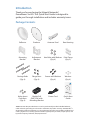
Introduction
Thank you for purchasing the Ubiquiti Networks®
PowerBeam®acISO. This Quick Start Guide is designed to
guide you through installation and includes warranty terms.
Package Contents
Reflector Radome Antenna Feed Rear Housing
Mounting
Bracket
Adjustment
Bracket
Hex Bolts with Washers
(Qty. 4)
Pole Clamp
(Qty. 2)
Carriage Bolts
(Qty. 4)
Flange Nuts
(Qty. 4)
Screws with Washers
(Qty. 4)
Washers
(Qty. 4)
5 GHz airMAX
®
ac Bridge with
500 mm RF Isolated Reflector
Model: PBE-5AC-500-ISO
Nylon Insert
Lock Nuts
(Qty. 4)
Gigabit PoE
(24V, 0.5A) with
Mounting Bracket
Power Cord Quick Start
Guide
TERMS OF USE: Ubiquiti radio devices must be professionally installed. Shielded Ethernet
cable and earth grounding must be used as conditions of product warranty. TOUGHCable
™
is
designed for outdoor installations. It is the professional installer’s responsibility to follow local
country regulations, including operation within legal frequency channels, output power, and
Dynamic Frequency Selection (DFS) requirements.

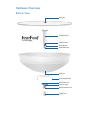
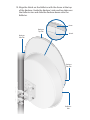
Hardware Overview
Bottom View
Cable Door
Rear Housing
Antenna Feed
Ethernet Port
Release Button Slot
Mounting Bracket
Release Button
Reflector
Alignment Pins
Reset Button
Radome
Technology

Reset Button To reset to factory defaults, press and hold the
Reset button for more than 10 seconds while the device is
poweredon. Alternatively, the device may be reset remotely
via a Reset button located on the bottom of the Gigabit
PoE adapter.
Release Button After you assemble the device, check the
Release button; it should be fully engaged in the Release Button
Slot of the Rear Housing. This ensures that the Antenna Feed is
locked into place. If you need to remove the Antenna Feed, you
must depress the Release button first.
LEDs
Power The Power LED will light blue when the
device is connected to a power source.
Ethernet The Ethernet LED will light steady blue
when an active Ethernet connection is made and
flash when there is activity.
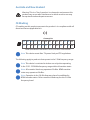
Signal In airOS®, you can modify the threshold
value for the wireless signal strength LEDs on the
Wireless tab under Signal LED Thresholds. Each LED
will light when the wireless signal strength is equal
to or greater than the LED’s threshold value. The
default threshold values for these LEDs are shown
below:
-65 dBm
-73 dBm
-80 dBm -94 dBm

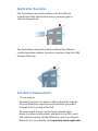
Application Examples
The PowerBeam mounted outdoors with the Reflector
installed provides directional outdoor coverage (gain is
reflector‑dependent).
The PowerBeam mounted outdoors without the Reflector
installed provides outdoor‑to‑indoor coverage using the 3 dBi
Antenna Feed only.
Installation Requirements
• 13 mm wrench
• Shielded Category 5 (or above) cabling should be used for
all wired Ethernet connections and should be grounded
through the AC ground of the PoE.
We recommend that you protect your networks from
harmful outdoor environments and destructive ESD events
with industrial‑grade, shielded Ethernet cable from Ubiquiti
Networks. For more details, visit www.ubnt.com/toughcable

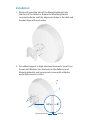
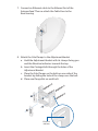
Installation
1. Align and insert the tabs of the Mounting Bracket into
the slots of the Reflector. Rotate the Mounting Bracket
counterclockwise until the alignment holes in the dish and
bracket align with each other.
2. For added support in high‑wind environments, insert four
Screws with Washers into the holes in the Reflector and
Mounting Bracket, and secure each screw with a Washer
and a Nylon Insert Lock Nut.
Mounting Bracket
Reflector

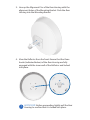
3. Line up the Alignment Pins of the Rear Housing with the
alignment holes of the Mounting Bracket. Push the Rear
Housing into the Mounting Bracket.
4. View the Reflector from the front. Ensure that the three
hooks (indicated below) of the Rear Housing are fully
engaged with the inner wall of the Reflector and locked
into place.
IMPORTANT: Before proceeding, lightly pull the Rear
Housing to confirm that it is locked into place.

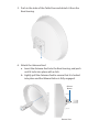
5. Push in the sides of the Cable Door and detach it from the
Rear Housing.
6. Attach the Antenna Feed.
a. Insert the Antenna Feed into the Rear Housing, and push
until it locks into place with a click.
b. Lightly pull the Antenna Feed to ensure that it is locked
into place and the Release Button is fully engaged.
Release
Button
Bottom View

7. Connect an Ethernet cable to the Ethernet Port of the
Antenna Feed. Then re‑attach the Cable Door to the
RearHousing.
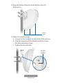
8. Attach the Pole Clamps to the Adjustment Bracket.
a. Hold the Adjustment Bracket with its clamps facing you
and the Elevation Indicators towards the top.
b. Insert the Carriage Bolts through the holes of the
Adjustment Bracket.
c. Place the Pole Clamps on the bolts on one side of the
bracket by sliding the hole of the clamp over the bolt.
d. Place one Flange Nut on each bolt.
Elevation
Indicator

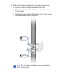
9. Mount the Adjustment Bracket on the pole and secure it.
a. Place the Adjustment Bracket against the pole.
b. Slide the slot of each Pole Clamp over the adjacent
Carriage Bolt.
c. Tighten the Flange Nuts of the bolts to 25 N · m to secure
the Adjustment Bracket to the pole.
25 N · m
25 N · m
Note: The mounting assembly can accommodate a
Ø 40 ‑ 80 mm pole.

10. Insert the Pivot Pins on the inside of the Adjustment Bracket
into the Mounting Bracket Slots.
Pivot Pin
(one on each side of
Adjustment Bracket)
Mounting
Bracket Slot

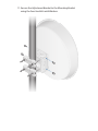
11. Secure the Adjustment Bracket to the Mounting Bracket
using the four Hex Bolts with Washers.

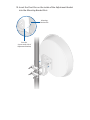
12. Align the Notch on the Reflector with the Arrow at the top
of the Radome. Guide the Radome’s side and top tabs over
the Reflector rim and slide the Radome down onto the
Reflector.
Arrow
Notch
Radome
Side Tab
Reflector
Rim
Radome
Side Tab
Radome
Top Tab

*640-00219-06*
640-00219-06
13. Snap the bottom three tabs of the Radome over the
Reflector rim.
Bottom
Tabs
14. Adjust the elevation angle.
a. Loosen the four Hex Bolts on both sides of the antenna.
b. Pivot the antenna until the Elevation Indicator shows
the desired elevation angle.
c. Tighten the four Hex Bolts.
10
20
Elevation
Indicator

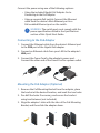
Connect the power using one of the following options:
• Using the included Gigabit PoE Adapter: Go to
Connecting to the PoE Adapter.
• Using a separate PoE switch: Connect the Ethernet
cable from the device’s Main Ethernet port to a
PoE‑enabled Ethernet port on the switch.
WARNING: The switch port must comply with the
power specifications listed in the Specifications
section of this Quick Start Guide.
Connecting to the PoE Adapter
1. Connect the Ethernet cable from the device’s Ethernet port
to the POE port of the Gigabit PoE adapter.
2. Connect an Ethernet cable from your LAN to the adapter’s
LAN port.
3. Connect the Power Cord to the adapter’s power port.
Connect the other end of the Power Cord to a power outlet.
Mounting the PoE Adapter (Optional)
1. Remove the PoE Mounting Bracket from the adapter, place
the bracket at the desired location, and mark the two holes.
2. Pre‑drill the holes if necessary, and secure the bracket
using two fasteners (not included).
3. Align the adapter’s slots with the tabs of the PoE Mounting
Bracket, and then slide the adapterdown.

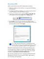
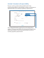
Accessing airOS
Verify connectivity in the airOS Configuration Interface.
1. Make sure that your host system is connected via Ethernet
to the device.
2. Configure the Ethernet adapter on your host system with a
static IP address on the 192.168.1.x subnet.
3. Launch your web browser and type https://192.168.1.20
in the address field. Press enter (PC) or return (Mac).
https://192.168.1.20
4. Enter ubnt in the Username and Password fields. Select
your Country and Language. You must agree to the Terms of
Use to use the product. Click Login.
500 ISO
Note: The Country setting for U.S. product versions
is restricted to a choice of Canada, Puerto Rico, or the
U.S. to ensure compliance with FCC/IC regulations.
The airOS Configuration Interface will appear, allowing you
to customize your settings as needed. For additional details
on the airOS Configuration Interface, refer to the User Guide
available at www.ubnt.com/download/airmax
You can also manage your device using the Ubiquiti Network
Management System. Setup using the UNMS
™
app requires
the U‑Installer, sold separately.

Installer Compliance Responsibility
Devices must be professionally installed and it is the
professional installer’s responsibility to make sure the device is
operated within local country regulatory requirements.
Since Ubiquiti Networks equipment can be paired with a
variety of antennas and cables, the Antenna and Output Power
fields are provided to the professional installer to assist in
meeting regulatory requirements.

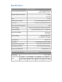
Specifications
PBE‑5AC‑500‑ISO
Dimensions (with Radome) 564 x 564 x 308 mm
(22.20 x 22.20 x 12.13")
Weight (Mount Included) 5.2 kg
(11.5 lb)
Gain 27 dBi
Networking Interface (1) 10/100/1000 Ethernet Port
Enclosure Outdoor UV Stabilized Plastic
Max. Power Consumption 8W
Power Supply 24V, 0.5A Gigabit PoE Adapter (Included)
Power Method Passive PoE (Pairs 4, 5+; 7, 8 Return)
Wind Survivability 200 km/h
(125 mph)
Wind Loading 984 N @ 200 km/h
(221.2 lbf @ 125 mph)
Certications CE, FCC, IC
Mounting Pole Mounting Kit Included
Operating Temperature ‑40 to 70° C (‑40 to 158° F)
Operating Humidity 5 to 95% Noncondensing
Shock and Vibrations ETSI300‑019‑1.4
Operating Frequency (MHz)
Worldwide 5150 ‑ 5875
USA
U-NII-1 U‑NII‑2A U‑NII‑2C U‑NII‑3
5150 ‑ 5250 5250 ‑ 5350 5470 ‑ 5725 5725 ‑ 5850

Safety Notices
1. Read, follow, and keep these instructions.
2. Heed all warnings.
3. Only use attachments/accessories specified by the manufacturer.
WARNING: Do not use this product in a location that can
be submerged by water.
WARNING: Avoid using this product during an electrical
storm. There may be a remote risk of electric shock from
lightning.
Electrical Safety Information
1. Compliance is required with respect to voltage, frequency, and current
requirements indicated on the manufacturer’s label. Connection to a
different power source than those specified may result in improper
operation, damage to the equipment or pose a fire hazard if the
limitations are not followed.
2. There are no operator serviceable parts inside this equipment. Service
should be provided only by a qualified service technician.
3. This equipment is provided with a detachable power cord which has
an integral safety ground wire intended for connection to a grounded
safety outlet.
a. Do not substitute the power cord with one that is not the provided
approved type. Never use an adapter plug to connect to a 2‑wire
outlet as this will defeat the continuity of the grounding wire.
b. The equipment requires the use of the ground wire as a part of the
safety certification, modification or misuse can provide a shock
hazard that can result in serious injury or death.
c. Contact a qualified electrician or the manufacturer if there
are questions about the installation prior to connecting the
equipment.
d. Protective earthing is provided by Listed AC adapter. Building
installation shall provide appropriate short‑circuit backup
protection.
e. Protective bonding must be installed in accordance with local
national wiring rules and regulations.

Limited Warranty
UBIQUITI NETWORKS, Inc (“UBIQUITI NETWORKS”) warrants that the
product(s) furnished hereunder (the “Product(s)”) shall be free from defects
in material and workmanship for a period of one (1) year from the date
of shipment by UBIQUITI NETWORKS under normal use and operation.
UBIQUITI NETWORKS’ sole and exclusive obligation and liability under
the foregoing warranty shall be for UBIQUITI NETWORKS, at its discretion,
to repair or replace any Product that fails to conform to the above
warranty during the above warranty period. The expense of removal and
reinstallation of any Product is not included in this warranty. The warranty
period of any repaired or replaced Product shall not extend beyond its
original term.
Warranty Conditions
The above warranty does not apply if the Product:
(I) has been modified and/or altered, or an addition made thereto,
except by Ubiquiti Networks, or Ubiquiti Networks’ authorized
representatives, or as approved by Ubiquiti Networks in writing;
(II) has been painted, rebranded or physically modified in any way;
(III) has been damaged due to errors or defects in cabling;
(IV) has been subjected to misuse, abuse, negligence, abnormal
physical, electromagnetic or electrical stress, including lightning
strikes, or accident;
(V) has been damaged or impaired as a result of using third party
firmware;
(VI) has no original Ubiquiti MAC label, or is missing any other original
Ubiquiti label(s); or
(VII) has not been received by Ubiquiti within 30 days of issuance of
the RMA.
In addition, the above warranty shall apply only if: the product has been
properly installed and used at all times in accordance, and in all material
respects, with the applicable Product documentation; all Ethernet cabling
runs use CAT5 (or above), and for outdoor installations, shielded Ethernet
cabling is used, and for indoor installations, indoor cabling requirements
are followed.
Returns
No Products will be accepted for replacement or repair without obtaining
a Return Materials Authorization (RMA) number from UBIQUITI NETWORKS
during the warranty period, and the Products being received at UBIQUITI
NETWORKS’ facility freight prepaid in accordance with the RMA process of
UBIQUITI NETWORKS. Products returned without an RMA number will not
be processed and will be returned freight collect or subject to disposal.
Information on the RMA process and obtaining an RMA number can be
found at: www.ubnt.com/support/warranty
Pagina se încarcă ...
Pagina se încarcă ...
Pagina se încarcă ...
Pagina se încarcă ...
Pagina se încarcă ...
Pagina se încarcă ...
Pagina se încarcă ...
Pagina se încarcă ...
-
 1
1
-
 2
2
-
 3
3
-
 4
4
-
 5
5
-
 6
6
-
 7
7
-
 8
8
-
 9
9
-
 10
10
-
 11
11
-
 12
12
-
 13
13
-
 14
14
-
 15
15
-
 16
16
-
 17
17
-
 18
18
-
 19
19
-
 20
20
-
 21
21
-
 22
22
-
 23
23
-
 24
24
-
 25
25
-
 26
26
-
 27
27
-
 28
28


Ubiquiti PowerBeam PBE-5AC-500-ISO Ghid de inițiere rapidă
- Categorie
- Antene de rețea
- Tip
- Ghid de inițiere rapidă
în alte limbi
Lucrări conexe
-
Ubiquiti LAP-120 Ghid de inițiere rapidă
-
-
-
Ubiquiti Networks PBM365 Specificație
-
-
-
Ubiquiti Networks NanoBeam NBE-M5-400 Ghid de inițiere rapidă
-
-
-
