Makita DTW1001 Manual de utilizare
- Categorie
- Unelte electrice
- Tip
- Manual de utilizare

DTW1001
DTW1002
DTW800
DTW1001XV
DTW1002XV
DTW800XV
EN Cordless Impact Wrench INSTRUCTION MANUAL 4
PL Akumulatorowy klucz
udarowy INSTRUKCJA OBSŁUGI 13
HU Akkumulátoros csavarkulcs HASZNÁLATI KÉZIKÖNYV 22
SK Akumulátorový razový
uťahovač NÁVOD NA OBSLUHU 31
CS Akumulátorový rázový
utahovák NÁVOD K OBSLUZE 40
UK Бездротовий ударний
гайковерт
ІНСТРУКЦІЯ З
ЕКСПЛУАТАЦІЇ 49
RO Maşină de înşurubat cu
impact cu acumulator MANUAL DE INSTRUCŢIUNI 58
DE Akku-Schlagschrauber BETRIEBSANLEITUNG 67

1
2
3
Fig.1
1
Fig.2
1
2
Fig.3
1
Fig.4
1
Fig.5
1
Fig.6
AB
1
Fig.7
1
2
3
4
5
Fig.8
2

1
2
Fig.9
2
3
1
Fig.10
A
Fig.11
1
2
Fig.12
2
1
3
Fig.13
1
2
3
Fig.14
Fig.15
3

4ENGLISH
ENGLISH (Original instructions)
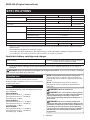
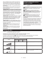
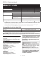
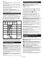
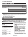
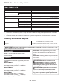
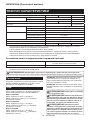
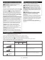
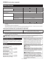
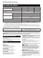
SPECIFICATIONS
Model:
DTW1001 / DTW1001XV DTW1002 / DTW1002XV DTW800 / DTW800XV
Fastening capacities Standard bolt M12 - M30 M12 - M24
High tensile bolt M10 - M24 M10 - M22
Square drive 19 mm 12.7 mm –
Drive shank –11.1 mm Hex.
No load speed Hard impact mode 0 - 1,800 min-1
Medium impact mode 0 - 1,000 min-1
Soft impact mode 0 - 900 min-1
Impacts per minute Hard impact mode 0 - 2,200 min-1
Medium impact mode 0 - 2,000 min-1
Soft impact mode 0 - 1,800 min-1
Overall length 229 mm
Rated voltage D.C. 18 V
Net weight 3.4 - 3.7 kg 3.3 - 3.6 kg 3.4 - 3.7 kg
• Due to our continuing program of research and development, the specications herein are subject to change
without notice.
• Specications may differ from country to country.
• The weight may differ depending on the attachment(s), including the battery cartridge. The lightest and heavi-
est combination, according to EPTA-Procedure 01/2014, are shown in the table.
Applicable battery cartridge and charger
Battery cartridge BL1815N / BL1820 / BL1820B / BL1830 / BL1830B / BL1840 /
BL1840B / BL1850 / BL1850B / BL1860B
Charger DC18RC / DC18RD / DC18RE / DC18SD / DC18SE / DC18SF
• Some of the battery cartridges and chargers listed above may not be available depending on your region of
residence.
WARNING: Only use the battery cartridges and chargers listed above. Use of any other battery cartridges
and chargers may cause injury and/or re.
Intended use
The tool is intended for fastening bolts and nuts.
Model DTW800 / DTW800XV: The tool is also intended
for drilling into wood.
Noise
The typical A-weighted noise level determined accord-
ing to EN62841:
Model DTW1001
Sound pressure level (LpA):98 dB(A)
Sound power level (LWA):109 dB (A)
Uncertainty (K) :3dB(A)
Model DTW1002
Sound pressure level (LpA):97 dB(A)
Sound power level (LWA):108 dB (A)
Uncertainty (K) :3dB(A)
Model DTW800
Sound pressure level (LpA):95 dB(A)
Sound power level (LWA):106 dB (A)
Uncertainty (K) :3dB(A)
NOTE: The declared noise emission value(s) has
been measured in accordance with a standard test
method and may be used for comparing one tool with
another.
NOTE: The declared noise emission value(s)
may also be used in apreliminary assessment of
exposure.
WARNING: Wear ear protection.
WARNING: The noise emission during actual
use of the power tool can differ from the declared
value(s) depending on the ways in which the
tool is used especially what kind of workpiece is
processed.
WARNING: Be sure to identify safety mea-
sures to protect the operator that are based on an
estimation of exposure in the actual conditions of
use (taking account of all parts of the operating
cycle such as the times when the tool is switched
off and when it is running idle in addition to the
trigger time).

5ENGLISH
Vibration
The vibration total value (tri-axial vector sum) deter-
mined according to EN62841:
Model DTW1001
Work mode: impact tightening of fasteners of the maxi-
mum capacity of the tool
Vibration emission (ah):15.5 m/s2
Uncertainty (K) :2.0 m/s2
Model DTW1002
Work mode: impact tightening of fasteners of the maxi-
mum capacity of the tool
Vibration emission (ah):18.0 m/s2
Uncertainty (K) :1.5 m/s2
Model DTW800
Work mode: impact tightening of fasteners of the maxi-
mum capacity of the tool
Vibration emission (ah):24.0 m/s2
Uncertainty (K) :2.0 m/s2
Work mode: drilling into wood
Vibration emission (ah):7.0 m/s2
Uncertainty (K) :1.5 m/s2
NOTE: The declared vibration total value(s) has been
measured in accordance with a standard test method
and may be used for comparing one tool with another.
NOTE: The declared vibration total value(s) may also
be used in apreliminary assessment of exposure.
WARNING: The vibration emission during
actual use of the power tool can differ from the
declared value(s) depending on the ways in which
the tool is used especially what kind of workpiece
is processed.
WARNING: Be sure to identify safety mea-
sures to protect the operator that are based on an
estimation of exposure in the actual conditions of
use (taking account of all parts of the operating
cycle such as the times when the tool is switched
off and when it is running idle in addition to the
trigger time).
EC Declaration of Conformity
For European countries only
The EC declaration of conformity is included as Annex A
to this instruction manual.
General power tool safety warnings
WARNING: Read all safety warnings, instruc-
tions, illustrations and specications provided
with this power tool. Failure to follow all instructions
listed below may result in electric shock, re and/or
serious injury.
Save all warnings and instruc-
tions for future reference.
The term "power tool" in the warnings refers to your
mains-operated (corded) power tool or battery-operated
(cordless) power tool.
Cordless impact wrench safety
warnings
1. Hold the power tool by insulated gripping
surfaces, when performing an operation
where the fastener may contact hidden wiring.
Fasteners contacting a"live" wire may make
exposed metal parts of the power tool "live" and
could give the operator an electric shock.
2. Wear ear protectors.
3. Check the impact socket carefully for wear,
cracks or damage before installation.
4. Hold the tool rmly.
5. Always be sure you have a rm footing.
Be sure no one is below when using the tool in
high locations.
6. The proper fastening torque may differ
depending upon the kind or size of the bolt.
Check the torque with a torque wrench.
7. Use auxiliary handle(s), if supplied with the
tool. Loss of control can cause personal injury.
8. Hold the power tool by insulated gripping
surfaces, when performing an operation where
the cutting accessory may contact hidden
wiring. Cutting accessory contacting a"live"
wire may make exposed metal parts of the power
tool "live" and could give the operator an electric
shock.
9. Keep hands away from rotating parts.
10. Do not touch the drill bit or the workpiece
immediately after operation; they may be
extremely hot and could burn your skin.
11. Some material contains chemicals which may
be toxic. Take caution to prevent dust inhala-
tion and skin contact. Follow material supplier
safety data.
SAVE THESE INSTRUCTIONS.
WARNING: DO NOT let comfort or familiarity
with product (gained from repeated use) replace
strict adherence to safety rules for the subject
product.
MISUSE or failure to follow the safety rules stated
in this instruction manual may cause serious
personal injury.
Important safety instructions for
battery cartridge
1. Before using battery cartridge, read all instruc-
tions and cautionary markings on (1) battery
charger, (2) battery, and (3) product using
battery.
2. Do not disassemble battery cartridge.
3. If operating time has become excessively
shorter, stop operating immediately. It may
result in a risk of overheating, possible burns
and even an explosion.
4. If electrolyte gets into your eyes, rinse them
out with clear water and seek medical atten-
tion right away. It may result in loss of your
eyesight.

6ENGLISH
5. Do not short the battery cartridge:
(1) Do not touch the terminals with any con-
ductive material.
(2) Avoid storing battery cartridge in a con-
tainer with other metal objects such as
nails, coins, etc.
(3) Do not expose battery cartridge to water
or rain.
A battery short can cause a large current
ow, overheating, possible burns and even a
breakdown.
6. Do not store the tool and battery cartridge in
locations where the temperature may reach or
exceed 50 °C (122 °F).
7. Do not incinerate the battery cartridge even if
it is severely damaged or is completely worn
out. The battery cartridge can explode in a re.
8. Be careful not to drop or strike battery.
9. Do not use a damaged battery.
10.
The contained lithium-ion batteries are subject to
the Dangerous Goods Legislation requirements.
For commercial transports e.g. by third parties,
forwarding agents, special requirement on pack-
aging and labeling must be observed.
For preparation of the item being shipped, consult-
ing an expert for hazardous material is required.
Please also observe possibly more detailed
national regulations.
Tape or mask off open contacts and pack up the
battery in such amanner that it cannot move
around in the packaging.
11. When disposing the battery cartridge, remove
it from the tool and dispose of it in a safe
place. Follow your local regulations relating to
disposal of battery.
12. Use the batteries only with the products
specied by Makita. Installing the batteries to
non-compliant products may result in are, exces-
sive heat, explosion, or leak of electrolyte.
13. If the tool is not used for a long period of time,
the battery must be removed from the tool.
SAVE THESE INSTRUCTIONS.
CAUTION: Only use genuine Makita batteries.
Use of non-genuine Makita batteries, or batteries that
have been altered, may result in the battery bursting
causing res, personal injury and damage. It will
also void the Makita warranty for the Makita tool and
charger.
Tips for maintaining maximum
battery life
1.
Charge the battery cartridge before completely dis-
charged. Always stop tool operation and charge the
battery cartridge when you notice less tool power.
2. Never recharge a fully charged battery car-
tridge. Overcharging shortens the battery
service life.
3.
Charge the battery cartridge with room tempera-
ture at 10 °C - 40 °C (50 °F - 104 °F). Let a hot
battery cartridge cool down before charging it.
4. Charge the battery cartridge if you do not use
it for a long period (more than six months).
FUNCTIONAL
DESCRIPTION
CAUTION: Always be sure that the tool is
switched off and the battery cartridge is removed
before adjusting or checking function on the tool.
Installing or removing battery
cartridge
CAUTION: Always switch off the tool before
installing or removing of the battery cartridge.
CAUTION: Hold the tool and the battery car-
tridge rmly when installing or removing battery
cartridge. Failure to hold the tool and the battery
cartridge rmly may cause them to slip off your hands
and result in damage to the tool and battery cartridge
and apersonal injury.
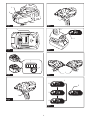
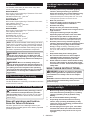
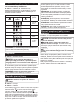
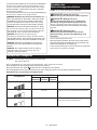
►Fig.1: 1. Red indicator 2. Button 3. Battery cartridge
To remove the battery cartridge, slide it from the tool
while sliding the button on the front of the cartridge.
To install the battery cartridge, align the tongue on the
battery cartridge with the groove in the housing and slip
it into place. Insert it all the way until it locks in place
with alittle click. If you can see the red indicator on the
upper side of the button, it is not locked completely.
CAUTION: Always install the battery cartridge
fully until the red indicator cannot be seen. If not,
it may accidentally fall out of the tool, causing injury to
you or someone around you.
CAUTION: Do not install the battery cartridge
forcibly. If the cartridge does not slide in easily, it is
not being inserted correctly.
Battery protection system
Lithium-ion battery with star marking
►Fig.2: 1. Star marking
Lithium-ion batteries with a star marking are equipped
with aprotection system. This system automatically
cuts off power to the tool to extend battery life.
The tool will automatically stop during operation if the
tool and/or battery are placed under one of the following
conditions:
Overloaded:
The tool is operated in a manner that causes it to draw
an abnormally high current.
In this situation, turn the tool off and stop the application
that caused the tool to become overloaded. Then turn
the tool on to restart.
If the tool does not start, the battery is overheated. In
this situation, let the battery cool before turning the tool
on again.
Low battery voltage:
The remaining battery capacity is too low and the tool
will not operate. In this situation, remove and recharge
the battery.

7ENGLISH
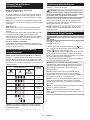
Indicating the remaining battery capacity
Only for battery cartridges with the indicator
►Fig.3: 1. Indicator lamps 2. Check button
Press the check button on the battery cartridge to indi-
cate the remaining battery capacity. The indicator lamps
light up for a few seconds.
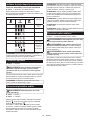
Indicator lamps Remaining
capacity
Lighted Off Blinking
75% to 100%
50% to 75%
25% to 50%
0% to 25%
Charge the
battery.
The battery
may have
malfunctioned.
NOTE: Depending on the conditions of use and the
ambient temperature, the indication may differ slightly
from the actual capacity.
Switch action
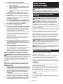
►Fig.4: 1. Switch trigger
CAUTION: Before installing the battery car-
tridge into the tool, always check to see that the
switch trigger actuates properly and returns to
the "OFF" position when released.
To start the tool, simply pull the switch trigger. Tool
speed is increased by increasing pressure on the switch
trigger. Release the switch trigger to stop.
NOTE: The tool automatically stops if you keep pull-
ing the switch trigger for about 6 minutes.
Lighting up the front lamp
CAUTION: Do not look in the light or see the
source of light directly.
►Fig.5: 1. Lamp
►Fig.6: 1. Button
To turn on the lamp status, press the button for
one second. To turn off the lamp status, press the but-
ton for one second again.
With the lamp status ON, pull the switch trigger to turn on
the lamp. To turn off, release it. The lamp goes out approx-
imately 10 seconds after releasing the switch trigger.
With the lamp status OFF, the lamp does not turn on
even if pulling the trigger.
NOTE: To conrm the lamp status, pull the trigger.
When the lamp lights up by pulling the switch trigger,
the lamp status is ON. When the lamp does not come
on, the lamp status is OFF.
NOTE: When the tool is overheated, the light ashes
for one minute, and then the LED display goes off. In
this case, cool down the tool before operating again.
NOTE: Use adry cloth to wipe the dirt off the lens of
the lamp. Be careful not to scratch the lens of lamp, or
it may lower the illumination.
NOTE: While pulling the switch trigger, the lamp
status cannot be changed.
NOTE: For approximately 10 seconds after releasing
the switch trigger, the lamp status can be changed.
Reversing switch action
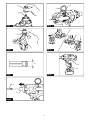
►Fig.7: 1. Reversing switch lever
CAUTION: Always check the direction of
rotation before operation.
CAUTION: Use the reversing switch only after
the tool comes to a complete stop. Changing the
direction of rotation before the tool stops may dam-
age the tool.
CAUTION: When not operating the tool,
always set the reversing switch lever to the neu-
tral position.
This tool has a reversing switch to change the direction
of rotation. Depress the reversing switch lever from the
A side for clockwise rotation or from the B side for coun-
terclockwise rotation.
When the reversing switch lever is in the neutral posi-
tion, the switch trigger cannot be pulled.

8ENGLISH
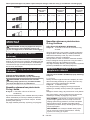
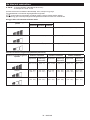
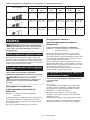
Changing the impact force
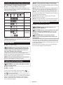
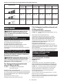
►Fig.8: 1. Changed in three steps 2. Hard 3. Medium
4. Soft 5. Button
You can change the impact in three steps: hard, medium and soft mode.
This allows a tightening suitable to the work.
Every time the button is pressed, the number of blows changes in three steps.
For approximately one minute after releasing the switch trigger, the impact force can be changed.
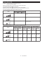
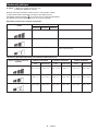
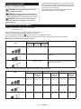
Specications of each impact force grade
Impact force grade displayed on
panel Maximum blows Application
DTW1001 /
DTW1001XV DTW1002 /
DTW1002XV
DTW800 /
DTW800XV
Hard 2,200 min-1 (/min) Tightening when force and speed are desired.
Medium 2,000 min-1 (/min) Tightening when you need good controlled power.
Soft 1,800 min-1 (/min) Tightening when you need ne adjustment with
small diameter bolt.
Impact force/bolt size corresponding chart (reference)
Impact force grade displayed on
panel DTW1001 / DTW1001XV DTW1002 / DTW1002XV DTW800 / DTW800XV
Standard bolt High tensile
bolt
Standard bolt High tensile
bolt
Standard bolt High tensile
bolt
Hard M20 - M30
(3/4″ -1-1/4″) M16 - M24
(5/8″ -1″) M20 - M30
(3/4″ -1-1/4″) M16 - M24
(5/8″ -1″) M20 - M24
(3/4″ -1″) M16 - M22
(5/8″ -7/8″)
Medium M16 - M24
(5/8″ -1″) M12 - M20
(1/2″ -3/4″) M16 - M24
(5/8″ -1″) M12 - M20
(1/2″ -3/4″) M14 - M20
(9/16″ -3/4″) M10 - M16
(3/8″ -5/8″)
Soft M12 - M20
(1/2″ -3/4″) M10 - M16
(3/8″ -5/8″) M12 - M20
(1/2″ -3/4″) M10 - M16
(3/8″ -5/8″) M12 - M16
(1/2″ -5/8″) M10 - M12
(3/8″ -1/2″)

9ENGLISH
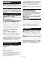
ASSEMBLY
CAUTION: Always be sure that the tool is
switched off and the battery cartridge is removed
before carrying out any work on the tool.
Selecting correct impact socket
Always use the correct size impact socket for bolts and
nuts. An incorrect size impact socket will result in inac-
curate and inconsistent fastening torque and/or damage
to the bolt or nut.
Installing or removing impact socket
Only for Model DTW1001 / DTW1002 / DTW1001XV /
DTW1002XV (optional accessory)
CAUTION: Make sure that the impact socket
and the mounting portion are not damaged before
installing the impact socket.
For impact socket without O-ring
and pin
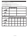
►Fig.9: 1. Impact socket 2. Square drive
Align the square of the impact socket with the square
drive and push the impact socket onto the square drive
until it locks into place. Tap it lightly if required.
To remove the impact socket, simply pull it off.
For impact socket with O-ring
and pin
Only for Model DTW1001 / DTW1001XV
►Fig.10: 1. Impact socket 2. O-ring 3. Pin
Move the O-ring out of the groove in the impact socket
and remove the pin from the impact socket. Fit the
impact socket onto the square drive so that the hole in
the impact socket is aligned with the hole in the square
drive.
Insert the pin through the hole in the impact socket and
square drive. Then return the O-ring to the original posi-
tion in the impact socket groove to retain the pin.
To remove the impact socket, follow the installation
procedures in reverse.
Installing or removing drill bit/
socket adapter
Only for Model DTW800 / DTW800XV (optional
accessory)
►Fig.11
A=11.2 mm
Use only the drill bit/socket adapter shown in the gure.
Do not use any other drill bit/socket adapter.
►Fig.12: 1. Drill bit 2. Sleeve
To install the drill bit, pull the sleeve in the direction of the
arrow and insert the drill bit into the sleeve as far as it will go.
Then release the sleeve to secure the drill bit.
To remove the drill bit, pull the sleeve in the direction of
the arrow and pull the drill bit out.
NOTE: If the drill bit is not inserted deep enough into
the sleeve, the sleeve will not return to its original
position and the drill bit will not be secured. In this
case, try re-inserting the drill bit according to the
instructions above.
NOTE: After inserting the drill bit, make sure that it is
rmly secured. If it comes out, do not use it.
Ring
Only for Model DTW800 / DTW800XV
►Fig.13: 1. Bracket 2. Ring 3. Screws
The ring is convenient for hanging the tool with hoist.
First, place the rope through the ring. Then hang the
tool up to the air with hoist.
CAUTION: Before using the ring, always
make sure that the bracket and ring are secured
and not damaged.
Installing hook
►Fig.14: 1. Groove 2. Hook 3. Screw
The hook is convenient for temporarily hanging the tool.
This can be installed on either side of the tool. To install
the hook, insert it into a groove in the tool housing
on either side and then secure it with two screws. To
remove, loosen the screws and then take it out.
OPERATION
CAUTION: Always insert the battery cartridge
all the way until it locks in place. If you can see the
red indicator on the upper side of the button, it is not
locked completely. Insert it fully until the red indicator
cannot be seen. If not, it may accidentally fall out of
the tool, causing injury to you or someone around
you.
►Fig.15
Hold the tool rmly and place the impact socket over
the bolt or nut. Turn the tool on and fasten for the proper
fastening time.
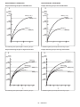
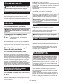
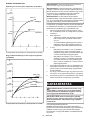
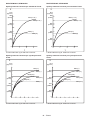
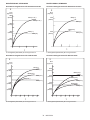
The proper fastening torque may differ depending upon
the kind or size of the bolt, the material of the workpiece
to be fastened, etc. The relation between fastening
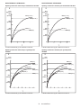
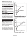
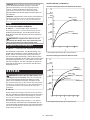
torque and fastening time is shown in the gures.

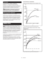
10 ENGLISH
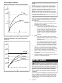
Model DTW1001 / DTW1001XV
Proper fastening torque for standard bolt
1
2
N•m
(kgf•cm)
800
600
400
200
(2040)
(4080)
(6120)
(8160)
1023
0
M24(1″)
M24(1″)
M30(1-1/4″)
M30(1-1/4″)
1. Fastening time (second) 2. Fastening torque
Proper fastening torque for high tensile bolt
1023456
0
800
600
400
200
(2040)
(4080)
(6120)
(8160)
N•m
(kgf•cm)
2
1
M24(1″)
M24(1″)
M22(7/8″)
M22(7/8″)
M20(3/4″)
M20(3/4″)
1. Fastening time (second) 2. Fastening torque
Model DTW1002 / DTW1002XV
Proper fastening torque for standard bolt
1
2
N•m
(kgf•cm)
800
600
400
200
(2040)
(4080)
(6120)
(8160)
1023
0
M24(1″)
M24(1″)
M30(1-1/4″)
M30(1-1/4″)
1. Fastening time (second) 2. Fastening torque
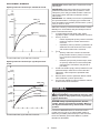
Proper fastening torque for high tensile bolt
1023456
0
800
600
400
200
(2040)
(4080)
(6120)
(8160)
N•m
(kgf•cm)
2
1
M24(1″)
M24(1″)
M22(7/8″)
M22(7/8″)
M20(3/4″)
M20(3/4″)
1. Fastening time (second) 2. Fastening torque

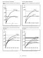
11 ENGLISH
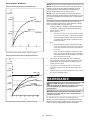
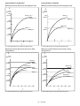
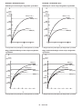
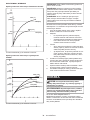
Model DTW800 / DTW800XV
Proper fastening torque for standard bolt
N•m
(kgf•cm)
1
1
02
3
0
400
200
(2040)
(4080)
M20(3/4″)
M20(3/4″)
M24(1″)
M24(1″)
2
1. Fastening time (second) 2. Fastening torque
Proper fastening torque for high tensile bolt
1023456
0
800
600
400
200
(2040)
(4080)
(6120)
(8160)
N•m
(kgf•cm)
1
2
M22(7/8″)
M20(3/4″)
M20(3/4″)
M16(5/8″)
M16(5/8″)
M22(7/8″)
1. Fastening time (second) 2. Fastening torque
NOTE: Hold the tool pointed straight at the bolt or nut.
NOTE: Excessive fastening torque may damage the
bolt/nut or impact socket. Before starting your job,
always perform atest operation to determine the
proper fastening time for your bolt or nut.
NOTE: If the tool is operated continuously until the
battery cartridge has discharged, allow the tool to rest
for 15 minutes before proceeding with afresh battery
cartridge.
The fastening torque is affected by awide variety of
factors including the following. After fastening, always
check the torque with a torque wrench.
1. When the battery cartridge is discharged almost
completely, voltage will drop and the fastening
torque will be reduced.
2. Impact socket
•Failure to use the correct size impact socket
will cause a reduction in the fastening torque.
• A worn impact socket (wear on the hex end
or square end) will cause areduction in the
fastening torque.
3. Bolt
• Even though the torque coefcient and the
class of bolt are the same, the proper fasten-
ing torque will differ according to the diame-
ter of bolt.
•Even though the diameters of bolts are the
same, the proper fastening torque will differ
according to the torque coefcient, the class
of bolt and the bolt length.
4. The use of the universal joint or the extension
bar somewhat reduces the fastening force of the
impact wrench. Compensate by fastening for a
longer period of time.
5. The manner of holding the tool or the material
of driving position to be fastened will affect the
torque.
6. Operating the tool at low speed will cause a reduc-
tion in the fastening torque.
MAINTENANCE
CAUTION: Always be sure that the tool is
switched off and the battery cartridge is removed
before attempting to perform inspection or
maintenance.
NOTICE: Never use gasoline, benzine, thinner,
alcohol or the like. Discoloration, deformation or
cracks may result.
To maintain product SAFETY and RELIABILITY,
repairs, any other maintenance or adjustment should
be performed by Makita Authorized or Factory Service
Centers, always using Makita replacement parts.

12
OPTIONAL
ACCESSORIES
CAUTION: These accessories or attachments
are recommended for use with your Makita tool
specied in this manual. The use of any other
accessories or attachments might present a risk of
injury to persons. Only use accessory or attachment
for its stated purpose.
If you need any assistance for more details regard-
ing these accessories, ask your local Makita Service
Center.
•Impact socket
• Drill bits (only for Model DTW800 /DTW800XV)
•Extension bar
• Universal joint
• Makita genuine battery and charger
NOTE: Some items in the list may be included in the
tool package as standard accessories. They may
differ from country to country.
ENGLISH

13 POLSKI
POLSKI (Instrukcja oryginalna)
DANE TECHNICZNE
Model:
DTW1001 / DTW1001XV DTW1002 / DTW1002XV DTW800 / DTW800XV
Zakresy dokręcania Śruba zwykła M12–M30 M12–M24
Śruba odużej wytrzymałości M10–M24 M10–M22
Zabierak kwadratowy 19 mm 12,7 mm –
Uchwyt gniazdowy –
Sześciokątny 11,1 mm
Prędkość bez obciążenia Tryb dużej siły udaru 0–1 800 min-1
Tryb średniej siły udaru 0–1 000 min-1
Tryb małej siły udaru 0–900 min-1
Liczba udarów na minutę Tryb dużej siły udaru 0–2 200 min-1
Tryb średniej siły udaru 0–2 000 min-1
Tryb małej siły udaru 0–1 800 min-1
Długość całkowita 229 mm
Napięcie znamionowe Prąd stały 18 V
Ciężar netto 3,4 - 3,7 kg 3,3 - 3,6 kg 3,4–3,7 kg
• W związku ze stale prowadzonym przez naszą rmę programem badawczo-rozwojowym niniejsze dane mogą
ulec zmianom bez wcześniejszego powiadomienia.
• Dane techniczne mogą różnić się wzależności od kraju.
• Masa może być różna wzależności od osprzętu, wtym akumulatora. Wtabeli przedstawiona jest najlżejsza i
najcięższa konguracja, zgodnie zprocedurą EPTA 01/2014.
Kompatybilne akumulatory i ładowarki
Akumulator BL1815N / BL1820 / BL1820B / BL1830 / BL1830B / BL1840 /
BL1840B / BL1850 / BL1850B / BL1860B
Ładowarka DC18RC / DC18RD / DC18RE / DC18SD / DC18SE / DC18SF
• Pewne zwymienionych powyżej akumulatorów iładowarek mogą być niedostępne wregionie zamieszkania
użytkownika.
OSTRZEŻENIE: Należy używać wyłącznie akumulatorów i ładowarek wymienionych powyżej.
Używanie innych akumulatorów iładowarek może stwarzać ryzyko wystąpienia obrażeń ciała lub pożaru.
Przeznaczenie
Narzędzie jest przeznaczone do dokręcania śrub i
nakrętek.
Model DTW800 /DTW800XV: Narzędzie jest przezna-
czone również do wiercenia wdrewnie.
Hałas
Typowy równoważny poziom dźwięku Aokreślony w
oparciu onormę EN62841:
Model DTW1001
Poziom ciśnienia akustycznego (LpA): 98 dB(A)
Poziom mocy akustycznej (LWA): 109 dB (A)
Niepewność (K): 3dB(A)
Model DTW1002
Poziom ciśnienia akustycznego (LpA): 97 dB(A)
Poziom mocy akustycznej (LWA): 108 dB (A)
Niepewność (K): 3dB(A)
Model DTW800
Poziom ciśnienia akustycznego (LpA): 95 dB(A)
Poziom mocy akustycznej (LWA): 106 dB (A)
Niepewność (K): 3dB(A)
WSKAZÓWKA: Deklarowana wartość emisji hałasu
została zmierzona zgodnie ze standardową metodą
testową imożna ją wykorzystać do porównywania
narzędzi.
WSKAZÓWKA: Deklarowaną wartość emisji hałasu
można także wykorzystać we wstępnej ocenie
narażenia.
OSTRZEŻENIE: Nosić ochronniki słuchu.
OSTRZEŻENIE: Poziom hałasu wytwa-
rzanego podczas rzeczywistego użytkowania
elektronarzędzia może się różnić od wartości
deklarowanej w zależności od sposobu użytko-
wania narzędzia, a w szczególności od rodzaju
obrabianego elementu.
OSTRZEŻENIE: W oparciu o szacowane
narażenie w rzeczywistych warunkach użytkowa-
nia należy określić środki bezpieczeństwa w celu
zapewnienia ochrony operatora (uwzględniając
wszystkie elementy cyklu działania, tj. czas, kiedy
narzędzie jest wyłączone i kiedy pracuje na biegu
jałowym, a także czas, kiedy jest włączone).

14 POLSKI
Drgania
Całkowita wartość poziomu drgań (suma wektorów w 3
osiach) określona zgodnie znormą EN62841:
Model DTW1001
Tryb pracy: dokręcanie udarowe śrub iwkrętów wmak-
symalnym zakresie możliwości narzędzia
Emisja drgań (ah): 15,5 m/s2
Niepewność (K): 2,0 m/s2
Model DTW1002
Tryb pracy: dokręcanie udarowe śrub iwkrętów wmak-
symalnym zakresie możliwości narzędzia
Emisja drgań (ah): 18,0 m/s2
Niepewność (K): 1,5 m/s2
Model DTW800
Tryb pracy: dokręcanie udarowe śrub iwkrętów wmak-
symalnym zakresie możliwości narzędzia
Emisja drgań (ah): 24,0m/s2
Niepewność (K): 2,0m/s2
Tryb pracy: wiercenie wdrewnie
Emisja drgań (ah): 7,0 m/s2
Niepewność (K): 1,5m/s2
WSKAZÓWKA: Deklarowana wartość poziomu
drgań została zmierzona zgodnie ze standardową
metodą testową imożna ją wykorzystać do porówny-
wania narzędzi.
WSKAZÓWKA: Deklarowaną wartość poziomu
drgań można także wykorzystać we wstępnej ocenie
narażenia.
OSTRZEŻENIE: Drgania wytwarzane pod-
czas rzeczywistego użytkowania elektronarzędzia
mogą się różnić od wartości deklarowanej w
zależności od sposobu użytkowania narzędzia,
a w szczególności od rodzaju obrabianego
elementu.
OSTRZEŻENIE: W oparciu o szacowane
narażenie w rzeczywistych warunkach użytkowa-
nia należy określić środki bezpieczeństwa w celu
zapewnienia ochrony operatora (uwzględniając
wszystkie elementy cyklu działania, tj. czas, kiedy
narzędzie jest wyłączone i kiedy pracuje na biegu
jałowym, a także czas, kiedy jest włączone).
Deklaracja zgodności WE
Dotyczy tylko krajów europejskich
Deklaracja zgodności WE jest dołączona jako załącznik
Ado niniejszej instrukcji obsługi.
Ogólne zasady bezpiecznej
eksploatacji elektronarzędzi
OSTRZEŻENIE: Należy zapoznać się z
ostrzeżeniami dotyczącymi bezpieczeństwa,
instrukcjami, ilustracjami i danymi technicz-
nymi dołączonymi do tego elektronarzędzia.
Niezastosowanie się do podanych poniżej instrukcji
może prowadzić do porażenia prądem, pożaru i/lub
poważnych obrażeń ciała.
Wszystkie ostrzeżenia i instruk-
cje należy zachować do wykorzy-
stania w przyszłości.
Pojęcie „elektronarzędzie", występujące wwymienio-
nych tu ostrzeżeniach, odnosi się do elektronarzędzia
zasilanego zsieci elektrycznej (z przewodem zasilają-
cym) lub do elektronarzędzia akumulatorowego (bez
przewodu zasilającego).
Ostrzeżenia dotyczące
bezpieczeństwa dla
akumulatorowego klucza
udarowego
1. Trzymać elektronarzędzie za izolowane
powierzchnie rękojeści podczas wykonywania
prac, przy których wkręcany wkręt lub śruba
mogą dotknąć niewidocznej instalacji elek-
trycznej. Zetknięcie wkrętu lub śruby zprzewo-
dem elektrycznym znajdującym się pod napięciem
spowoduje, że odsłonięte elementy metalowe
narzędzia również znajdą się pod napięciem, gro-
żąc porażeniem operatora prądem elektrycznym.
2. Nosić ochronniki słuchu.
3. Przed przystąpieniem do pracy sprawdzić
dokładnie gniazdo udarowe pod kątem zuży-
cia, pęknięć lub uszkodzeń.
4. Narzędzie należy trzymać mocno i pewnie.
5. Podczas pracy należy zadbać o dobre oparcie
dla nóg.
W przypadku pracy na pewnej wysokości
upewnić się, że na dole nie przebywają żadne
osoby.
6. Odpowiedni moment dokręcania zależy od
rodzaju i wielkości śruby. Moment dokrę-
cenia należy sprawdzać za pomocą klucza
dynamometrycznego.
7. Używać narzędzia z uchwytami pomocniczymi,
jeśli zostały dostarczone wraz z nim. Utrata
kontroli może spowodować obrażenia ciała.
8. Trzymać elektronarzędzie za izolowane
powierzchnie rękojeści podczas wykonywania
prac, przy których wiertło może dotknąć niewi-
docznej instalacji elektrycznej. Zetknięcie wier-
tła zprzewodem elektrycznym znajdującym się
pod napięciem może spowodować, że odsłonięte
elementy metalowe elektronarzędzia również
znajdą się pod napięciem, grożąc porażeniem
operatora prądem elektrycznym.
9. Trzymać ręce z dala od części obrotowych.
10. Nie dotykać wiertła ani części obrabianej od
razu po zakończeniu danej operacji; mogą one
być bardzo gorące i spowodować oparzenie
skóry.
11. Niektóre materiały zawierają substancje
chemiczne, które mogą być toksyczne.
Unikać wdychania pyłu i kontaktu ze skórą.
Przestrzegać przepisów bezpieczeństwa poda-
nych przez dostawcę materiałów.
ZACHOWAĆ NINIEJSZE
INSTRUKCJE.

15 POLSKI
OSTRZEŻENIE: NIE WOLNO pozwolić, aby
wygoda lub rutyna (nabyta w wyniku wielokrot-
nego używania urządzenia) zastąpiły ścisłe prze-
strzeganie zasad bezpieczeństwa obsługi.
NIEWŁAŚCIWE UŻYTKOWANIE narzędzia lub
niestosowanie się do zasad bezpieczeństwa
podanych w niniejszej instrukcji obsługi może
prowadzić do poważnych obrażeń ciała.
Ważne zasady bezpieczeństwa
dotyczące akumulatora
1. Przed użyciem akumulatora zapoznać się ze
wszystkimi instrukcjami i znakami ostrze-
gawczymi na (1) ładowarce, (2) akumulatorze
i (3) produkcie, w którym będzie używany
akumulator.
2. Akumulatora nie wolno rozbierać.
3. Jeśli czas działania uległ znacznemu skróce-
niu, należy natychmiast przerwać pracę. Może
bowiem dojść do przegrzania, ewentualnych
poparzeń, a nawet eksplozji.
4. W przypadku przedostania się elektrolitu do
oczu, przemyć je czystą wodą i niezwłocznie
uzyskać pomoc lekarską. Może on bowiem
spowodować utratę wzroku.
5. Nie doprowadzać do zwarcia akumulatora:
(1) Nie dotykać styków materiałami przewo-
dzącymi prąd.
(2) Unikać przechowywania akumulatora w
pojemniku z metalowymi przedmiotami,
takimi jak gwoździe, monety itp.
(3) Chronić akumulator przed deszczem lub
wodą.
Zwarcie prowadzi do przepływu prądu elek-
trycznego o dużym natężeniu i przegrzania
akumulatora, co w konsekwencji może grozić
poparzeniami a nawet awarią urządzenia.
6. Narzędzia i akumulatora nie wolno przecho-
wywać w miejscach, w których temperatura
osiąga bądź przekracza 50°C (122°F).
7. Akumulatorów nie wolno spalać, również tych
poważnie uszkodzonych lub całkowicie zuży-
tych. Akumulator może eksplodować w ogniu.
8. Chronić akumulator przed upadkiem i
uderzeniami.
9. Nie wolno używać uszkodzonego akumulatora.
10. Stanowiące wyposażenie akumulatory lito-
wo-jonowe podlegają przepisom dotyczącym
produktów niebezpiecznych.
Na potrzeby transportu komercyjnego, np. świad-
czonego przez rmy trzecie czy spedycyjne,
należy przestrzegać specjalnych wymagań w
zakresie pakowania ioznaczania etykietami.
Przygotowanie produktu do wysyłki wymaga
skonsultowania się ze specjalistą ds. materiałów
niebezpiecznych. Należy także przestrzegać
przepisów krajowych, które mogą być bardziej
szczegółowe.
Zakleić taśmą lub zaślepić otwarte styki akumula-
tora oraz zabezpieczyć go, aby nie mógł się prze-
suwać wopakowaniu.
11. Jeśli zajdzie konieczność utylizacji akumula-
tora, należy wyjąć go z narzędzia i przekazać
w bezpieczne miejsce. Postępować zgodnie z
przepisami lokalnymi dotyczącymi utylizacji
akumulatorów.
12. Używać akumulatorów tylko z produktami
określonymi przez rmę Makita. Zastosowanie
akumulatorów wniezgodnych produktach może
spowodować pożar, przegrzanie, wybuch lub
wyciek elektrolitu.
13. Jeśli narzędzie nie będzie używane przez dłuż-
szy czas, należy wyjąć z niego akumulator.
ZACHOWAĆ NINIEJSZE
INSTRUKCJE.
PRZESTROGA: Używać wyłącznie oryginal-
nych akumulatorów rmy Makita. Używanie nie-
oryginalnych akumulatorów rm innych niż Makita lub
akumulatorów, które zostały zmodykowane, może
spowodować wybuch akumulatora ipożar, obrażenia
ciała oraz zniszczenie mienia. Stanowi to również
naruszenie warunków gwarancji rmy Makita doty-
czących narzędzia iładowarki.
Wskazówki dotyczące zacho-
wania maksymalnej trwałości
akumulatora
1. Akumulator należy naładować zanim zostanie
do końca rozładowany. Po zauważeniu spadek
mocy narzędzia należy przerwać pracę i nała-
dować akumulator.
2. Nie wolno ładować powtórnie w pełni nałado-
wanego akumulatora. Przeładowanie akumula-
tora skraca jego trwałość.
3. Akumulator należy ładować w temperaturze
pokojowej w przedziale 10–40°C (50–104°F). W
przypadku gorącego akumulatora przed przy-
stąpieniem do ładowania należy poczekać, aż
ostygnie.
4. Akumulatory niklowo-wodorkowe należy nała-
dować po okresie długiego nieużytkowania
(dłuższego niż sześć miesięcy).

16 POLSKI
OPIS DZIAŁANIA
PRZESTROGA: Przed przystąpieniem do regu-
lacji lub przeglądu narzędzia upewnić się, że jest
ono wyłączone, a akumulator został wyjęty.
Wkładanie i wyjmowanie akumulatora
PRZESTROGA: Przed włożeniem lub wyjęciem
akumulatora należy zawsze wyłączyć narzędzie.
PRZESTROGA: Podczas wkładania lub wyjmo-
wania akumulatora należy mocno trzymać narzę-
dzie i akumulator. Wprzeciwnym razie mogą się one
wyślizgnąć zrąk, powodując uszkodzenie narzędzia
lub akumulatora iobrażenia ciała.
►Rys.1: 1. Czerwony wskaźnik 2. Przycisk
3. Akumulator
Aby wyjąć akumulator, przesuń przycisk znajdujący się
wprzedniej jego części iwysuń akumulator.
Aby włożyć akumulator, wyrównaj występ na akumulato-
rze zrowkiem wobudowie iwsuń go na swoje miejsce.
Akumulator należy wsunąć do oporu, aż się zatrzaśnie na
miejscu, co jest sygnalizowane delikatnym kliknięciem.
Jeśli wgórnej części przycisku jest widoczny czerwony
wskaźnik, akumulator nie został całkowicie zatrzaśnięty.
PRZESTROGA: Akumulator należy włożyć
do końca, tak aby czerwony wskaźnik nie był
widoczny. Wprzeciwnym razie może przypadkowo
wypaść znarzędzia, powodując obrażenia operatora
lub osób postronnych.
PRZESTROGA: Nie wkładać akumulatora na
siłę. Jeśli akumulator nie daje się swobodnie wsunąć,
oznacza to, że został włożony nieprawidłowo.
Układ zabezpieczenia akumulatora
Akumulator litowo-jonowy oznaczony gwiazdką
►Rys.2: 1. Znak gwiazdki
Akumulatory litowo-jonowe ze znakiem gwiazdki są
wyposażone wukład zabezpieczający. Układ ten auto-
matycznie odcina zasilanie narzędzia wcelu wydłuże-
nia żywotności akumulatora.
Narzędzie zostanie automatycznie zatrzymane pod-
czas pracy wnastępujących sytuacjach związanych z
narzędziem/akumulatorem:
Przeciążenie:
Narzędzie pracuje wsposób, który powoduje pobór
nadmiernie wysokiego prądu.
Wtakiej sytuacji należy wyłączyć narzędzie izaprze-
stać wykonywania czynności powodującej przeciążenie
narzędzia. Następnie należy włączyć narzędzie wcelu
jego ponownego uruchomienia.
Jeśli narzędzie nie uruchomi się, oznacza to, że aku-
mulator jest przegrzany. Wtakiej sytuacji, przed ponow-
nym uruchomieniem narzędzia należy odczekać, aż
akumulator ostygnie.
Niskie napięcie akumulatora:
Poziom naładowania akumulatora jest zbyt niski, aby
narzędzie mogło pracować. Wtakiej sytuacji należy
wyjąć akumulator igo naładować.
Wskazanie stanu naładowania
akumulatora
Tylko w przypadku akumulatorów ze wskaźnikiem
►Rys.3: 1. Lampki wskaźnika 2. Przycisk kontrolny
Nacisnąć przycisk kontrolny na akumulatorze wcelu
wyświetlenia stanu naładowania akumulatora. Lampki
wskaźnika zaświecą się przez kilka sekund.
Lampki wskaźnika Pozostała
energia
akumulatora
Świeci się Wyłączony Miga
75–100%
50–75%
25–50%
0–25%
Naładować
akumulator.
Akumulator
może nie
działać
poprawnie.
WSKAZÓWKA: Zależnie od warunków użytkowania
itemperatury otoczenia, wskazywany poziom może
nieznacznie się różnić od rzeczywistego stanu nała-
dowania akumulatora.
Działanie przełącznika
►Rys.4: 1. Spust przełącznika
PRZESTROGA: Przed włożeniem akumulatora
do narzędzia należy zawsze sprawdzić, czy spust
przełącznika działa prawidłowo i czy powraca do
położenia wyłączenia po jego zwolnieniu.
Wcelu uruchomienia narzędzia wystarczy pociągnąć
spust przełącznika. Prędkość narzędzia zwiększa się wraz
ze zwiększaniem nacisku na spust przełącznika. Wcelu
zatrzymania urządzenia należy zwolnić spust przełącznika.
WSKAZÓWKA: Narzędzie zatrzyma się automa-
tycznie, gdy spust przełącznika pozostanie wciśnięty
przez około 6min.
Włączanie lampki czołowej
PRZESTROGA: Nie patrzeć na światło ani
bezpośrednio na źródło światła.
►Rys.5: 1. Lampka
►Rys.6: 1. Przycisk
Wcelu włączenia trybu działania lampki oświetlenia
nacisnąć iprzytrzymać przez jedną sekundę przy-
cisk .Wcelu wyłączenia trybu działania lampki
oświetlenia ponownie nacisnąć iprzytrzymać przez
jedną sekundę przycisk .

17 POLSKI
Gdy tryb działania lampki oświetlenia jest włączony,
lampka oświetlenia włącza się po pociągnięciu spu-
stu przełącznika. Aby wyłączyć lampkę oświetlenia,
należy zwolnić spust przełącznika. Lampka oświetle-
nia wyłącza się po około 10 sod zwolnienia spustu
przełącznika.
Gdy tryb działania lampki oświetlenia jest wyłączony,
lampka oświetlenia nie włącza się po pociągnięciu
spustu przełącznika.
WSKAZÓWKA:Aby sprawdzić tryb działania lampki
oświetlenia, należy pociągnąć za spust przełącznika.
Jeśli po pociągnięciu za spust przełącznika lampka
oświetlenia włączy się, oznacza to, że tryb działania
lampki oświetlenia jest włączony. Jeśli lampka oświe-
tlenia nie włączy się, oznacza to, że tryb działania
lampki oświetlenia jest wyłączony.
WSKAZÓWKA: Wprzypadku przegrzania narzędzia,
lampka będzie migała przez jedną minutę, anastęp-
nie wyświetlacz LED zostanie wyłączony. Wtakiej
sytuacji należy poczekać, aż narzędzie ostygnie
przed dalszym jego użytkowaniem.
WSKAZÓWKA:Aby usunąć zabrudzenia zklosza
lampki, należy użyć suchej szmatki. Uważać, aby nie
zarysować klosza lampki, gdyż może to zmniejszyć
natężenie oświetlenia.
WSKAZÓWKA: Gdy spust przełącznika jest naci-
śnięty, nie można zmienić trybu działania lampki
oświetlenia.
WSKAZÓWKA: Tryb działania lampki oświetlenia
można zmienić po ok. 10 sod zwolnienia spustu
przełącznika.
Działanie przełącznika zmiany
kierunku obrotów
►Rys.7: 1. Dźwignia przełącznika zmiany kierunku
obrotów
PRZESTROGA: Przed przystąpieniem do pracy
należy zawsze sprawdzić ustawiony kierunek
obrotów.
PRZESTROGA: Przełącznika zmiany kie-
runku obrotów można użyć tylko po całkowitym
zatrzymaniu narzędzia. Zmiana kierunku obro-
tów przed zatrzymaniem się narzędzia grozi jego
uszkodzeniem.
PRZESTROGA: Gdy narzędzie nie jest uży-
wane, należy zawsze ustawić dźwignię prze-
łącznika zmiany kierunku obrotów w położeniu
neutralnym.
Omawiane narzędzie jest wyposażone wprzełącznik
umożliwiający zmianę kierunku obrotów. Wcelu uzy-
skania obrotów wprawą stronę należy wcisnąć dźwi-
gnię przełącznika zmiany kierunku obrotów po stronie
A, natomiast aby uzyskać obroty wlewą stronę, należy
wcisnąć dźwignię przełącznika po stronie B.
Gdy dźwignia przełącznika zmiany kierunku obrotów
znajduje się wpołożeniu neutralnym, spust przełącz-
nika jest zablokowany.
Zmiana siły udaru
►Rys.8: 1. Trzystopniowe ustawienie 2. Duża siła
3. Średnia siła 4. Mała siła 5. Przycisk
Dostępne są trzy stopnie ustawienia siły udaru: duża siła, średnia siła imała siła.
Umożliwia do dopasowanie siły dokręcania do rzeczywistych potrzeb.
Po każdym naciśnięciu przycisku następuje zmiana liczba udarów spośród jednego ztrzech ustawień.
Siłę udaru można zmienić po upływie ok. jednej minuty od zwolnienia spustu przełącznika.
Dane techniczne dotyczące stopnia siły udaru
Stopień siły udaru wyświetlany na
panelu Maksymalna częstotliwość udarów Zastosowanie
DTW1001 /
DTW1001XV DTW1002 /
DTW1002XV
DTW800 /
DTW800XV
Duża siła 2 200 min-1 (/min) Dokręcanie, gdy wymagana jest duża szybkość i
siła.
Średnia siła 2 000 min-1 (/min) Dokręcanie, gdy wymagana jest kontrolowana siła.
Mała siła 1 800 min-1 (/min) Dokręcanie, gdy wymagana jest dokładna regulacja
dla śrub omałej średnicy.

18 POLSKI
Tabela przedstawiająca siłę udaru odpowiednią dla danego rozmiaru śruby (o charakterze informacyjnym)
Stopień siły udaru wyświetlany
na panelu DTW1001 / DTW1001XV DTW1002 / DTW1002XV DTW800 / DTW800XV
Śruba zwykła Śruba o
dużej wytrzy-
małości
Śruba zwykła Śruba o
dużej wytrzy-
małości
Śruba zwykła Śruba o
dużej wytrzy-
małości
Duża siła M20 - M30
(3/4″ -1-1/4″) M16 - M24
(5/8″ -1″) M20 - M30
(3/4″ -1-1/4″) M16 - M24
(5/8″ -1″) M20 - M24
(3/4″ -1″) M16 - M22
(5/8″ -7/8″)
Średnia siła M16 - M24
(5/8″ -1″) M12 - M20
(1/2″ -3/4″) M16 - M24
(5/8″ -1″) M12 - M20
(1/2″ -3/4″) M14 - M20
(9/16″ -3/4″) M10 - M16
(3/8″ -5/8″)
Mała siła M12 - M20
(1/2″ -3/4″) M10 - M16
(3/8″ -5/8″) M12 - M20
(1/2″ -3/4″) M10 - M16
(3/8″ -5/8″) M12 - M16
(1/2″ -5/8″) M10 - M12
(3/8″ -1/2″)
MONTAŻ
PRZESTROGA: Przed przystąpieniem do prac
konserwacyjnych przy narzędziu upewnić się,
że jest ono wyłączone, a akumulator został wyjęty.
Wybór odpowiedniej nasadki
udarowej
Zawsze używać nasadek udarowych orozmiarze odpo-
wiednim do rozmiaru śrub inakrętek. Nasadka udarowa
oniewłaściwym rozmiarze prowadzi do niedokładnego
inierównomiernego momentu dokręcania i/lub uszko-
dzenia śruby lub nakrętki.
Zakładanie i zdejmowanie nasadki
udarowej
Tylko dla modelu DTW1001 / DTW1002 /
DTW1001XV / DTW1002XV (osprzęt dodatkowy)
PRZESTROGA: Przed założeniem nasadki
udarowej należy upewnić się, że sama nasadka
ani część mocująca nie są uszkodzone.
Nasadka udarowa bez pierścienia
O-ring i kołka
►Rys.9: 1. Nasadka udarowa 2. Zabierak
kwadratowy
Wyrównać kwadratowy otwór nasadki udarowej zzabie-
rakiem kwadratowym iwsunąć nasadkę na zabierak,
aż nasadka zablokuje się na swoim miejscu. Wrazie
potrzeby lekko puknąć.
Aby zdjąć nasadkę udarową, wystarczy je wyciągnąć.
Nasadka udarowa z pierścieniem
O-ring i kołkiem
Tylko dla modelu DTW1001 / DTW1001XV
►Rys.10: 1. Nasadka udarowa 2. Pierścień O-ring
3. Kołek
Wysunąć pierścień O-ring rowka wnasadce udarowej
iwyjąć kołek znasadki. Założyć nasadkę udarową na
zabieraku kwadratowym tak, aby otwór wnasadce
zrównał się zotworem wzabieraku.
Wsunąć kołek wotwór wnasadce izabieraku kwadra-
towym. Następnie zsunąć pierścień O-ring do rowka w
nasadce udarowej, aby zabezpieczyć kołek.
Aby zdjąć nasadkę udarową, należy wykonać czynności
procedury zakładania wodwrotnej kolejności.
Wkładanie i wyjmowanie wiertła /
adaptera do nasadek
Tylko dla modelu DTW800 / DTW800XV (osprzęt dodatkowy)
►Rys.11
A = 11,2 mm
Należy stosować wyłącznie wiertła /adaptery do nasa-
dek zkońcówką pokazaną na rysunku. Nie wolno uży-
wać innych wierteł /adapterów do nasadek.
►Rys.12: 1. Wiertło 2. Tuleja
Aby włożyć wiertło, pociągnąć za tuleję wkierunku
wskazanym strzałką iwsunąć wiertło jak najgłębiej do
tulei.
Następnie zwolnić tuleję, aby zamocować wniej wiertło.
Aby wyjąć wiertło, należy pociągnąć tuleję wkierunku
wskazanym strzałką iwyciągnąć zniej wiertło.
WSKAZÓWKA: Jeśli wiertło nie zostanie wsunięte
wystarczająco głęboko do tulei, tuleja nie wróci do
swojego pierwotnego położenia, awiertło nie będzie
dobrze zamocowane. Wtakim przypadku należy
spróbować ponownie włożyć wiertło zgodnie zpowyż-
szymi instrukcjami.
WSKAZÓWKA: Po wsunięciu wiertła należy upew-
nić się, że jest ono dobrze zamocowane. Jeśli się
wysuwa, nie należy go używać.

19 POLSKI
Pierścień
Tylko dla modelu DTW800 / DTW800XV
►Rys.13: 1. Uchwyt 2. Pierścień 3. Wkręty
Pierścień jest przydatny do zawieszenia narzędzia na
podnośniku. Najpierw przełożyć linę przez pierścień.
Następnie podwiesić narzędzie na podnośniku.
PRZESTROGA: Przed użyciem pierścienia
należy upewnić się, że uchwyt i pierścień są
dobrze przymocowane i nie są uszkodzone.
Zamontowanie zaczepu
►Rys.14: 1. Rowek 2. Zaczep 3. Wkręt
Zaczep służy do wygodnego, tymczasowego zawie-
szania narzędzia. Można go zamontować zjednej lub
zdrugiej strony narzędzia. Aby zamontować zaczep,
należy wsunąć go wrowek wobudowie narzędzia
znajdujący się zobu stron, anastępnie przykręcić go
dwoma wkrętami. Aby wymontować zaczep, należy
odkręcić wkręty iwyjąć zaczep.
OBSŁUGA
PRZESTROGA: Akumulator należy wsunąć
do oporu, aż wskoczy na swoje miejsce. Jeśli jest
widoczny czerwony wskaźnik wgórnej części przy-
cisku, akumulator nie został całkowicie zatrzaśnięty.
Należy go wsunąć do oporu, aż czerwony wskaźnik
przestanie być widoczny. Wprzeciwnym razie może
on przypadkowo wypaść znarzędzia, powodując
obrażenia operatora lub osób postronnych.
►Rys.15
Trzymać mocno narzędzie iumieścić nasadkę udarową
na śrubie lub nakrętce. Włączyć narzędzie idokręcać
przez odpowiedni czas.
Odpowiedni moment dokręcenia zależy od rodzaju i
rozmiaru śruby, materiału elementu, do którego wkręca
się śrubę itp. Zależność momentu dokręcenia iczasu
dokręcania pokazano na rysunkach.
Model DTW1001 / DTW1001XV
Właściwy moment dokręcenia dla zwykłych śrub
1
2
N•m
(kgf•cm)
800
600
400
200
(2040)
(4080)
(6120)
(8160)
1023
0
M24(1″)
M24(1″)
M30(1-1/4″)
M30(1-1/4″)
1. Czas dokręcania (s) 2. Moment dokręcenia
Właściwy moment dokręcenia dla śrub o dużej
wytrzymałości
1023456
0
800
600
400
200
(2040)
(4080)
(6120)
(8160)
N•m
(kgf•cm)
2
1
M24(1″)
M24(1″)
M22(7/8″)
M22(7/8″)
M20(3/4″)
M20(3/4″)
1. Czas dokręcania (s) 2. Moment dokręcenia

20 POLSKI
Model DTW1002 / DTW1002XV
Właściwy moment dokręcenia dla zwykłych śrub
1
2
N•m
(kgf•cm)
800
600
400
200
(2040)
(4080)
(6120)
(8160)
1023
0
M24(1″)
M24(1″)
M30(1-1/4″)
M30(1-1/4″)
1. Czas dokręcania (s) 2. Moment dokręcenia
Właściwy moment dokręcenia dla śrub o dużej
wytrzymałości
1023456
0
800
600
400
200
(2040)
(4080)
(6120)
(8160)
N•m
(kgf•cm)
2
1
M24(1″)
M24(1″)
M22(7/8″)
M22(7/8″)
M20(3/4″)
M20(3/4″)
1. Czas dokręcania (s) 2. Moment dokręcenia
Model DTW800 / DTW800XV
Właściwy moment dokręcenia dla zwykłych śrub
N•m
(kgf•cm)
1
1
02
3
0
400
200
(2040)
(4080)
M20(3/4″)
M20(3/4″)
M24(1″)
M24(1″)
2
1. Czas dokręcania (s) 2. Moment dokręcenia
Właściwy moment dokręcenia dla śrub o dużej
wytrzymałości
1023456
0
800
600
400
200
(2040)
(4080)
(6120)
(8160)
N•m
(kgf•cm)
1
2
M22(7/8″)
M20(3/4″)
M20(3/4″)
M16(5/8″)
M16(5/8″)
M22(7/8″)
1. Czas dokręcania (s) 2. Moment dokręcenia
Pagina se încarcă...
Pagina se încarcă...
Pagina se încarcă...
Pagina se încarcă...
Pagina se încarcă...
Pagina se încarcă...
Pagina se încarcă...
Pagina se încarcă...
Pagina se încarcă...
Pagina se încarcă...
Pagina se încarcă...
Pagina se încarcă...
Pagina se încarcă...
Pagina se încarcă...
Pagina se încarcă...
Pagina se încarcă...
Pagina se încarcă...
Pagina se încarcă...
Pagina se încarcă...
Pagina se încarcă...
Pagina se încarcă...
Pagina se încarcă...
Pagina se încarcă...
Pagina se încarcă...
Pagina se încarcă...
Pagina se încarcă...
Pagina se încarcă...
Pagina se încarcă...
Pagina se încarcă...
Pagina se încarcă...
Pagina se încarcă...
Pagina se încarcă...
Pagina se încarcă...
Pagina se încarcă...
Pagina se încarcă...
Pagina se încarcă...
Pagina se încarcă...
Pagina se încarcă...
Pagina se încarcă...
Pagina se încarcă...
Pagina se încarcă...
Pagina se încarcă...
Pagina se încarcă...
Pagina se încarcă...
Pagina se încarcă...
Pagina se încarcă...
Pagina se încarcă...
Pagina se încarcă...
Pagina se încarcă...
Pagina se încarcă...
Pagina se încarcă...
Pagina se încarcă...
Pagina se încarcă...
Pagina se încarcă...
Pagina se încarcă...
Pagina se încarcă...
-
 1
1
-
 2
2
-
 3
3
-
 4
4
-
 5
5
-
 6
6
-
 7
7
-
 8
8
-
 9
9
-
 10
10
-
 11
11
-
 12
12
-
 13
13
-
 14
14
-
 15
15
-
 16
16
-
 17
17
-
 18
18
-
 19
19
-
 20
20
-
 21
21
-
 22
22
-
 23
23
-
 24
24
-
 25
25
-
 26
26
-
 27
27
-
 28
28
-
 29
29
-
 30
30
-
 31
31
-
 32
32
-
 33
33
-
 34
34
-
 35
35
-
 36
36
-
 37
37
-
 38
38
-
 39
39
-
 40
40
-
 41
41
-
 42
42
-
 43
43
-
 44
44
-
 45
45
-
 46
46
-
 47
47
-
 48
48
-
 49
49
-
 50
50
-
 51
51
-
 52
52
-
 53
53
-
 54
54
-
 55
55
-
 56
56
-
 57
57
-
 58
58
-
 59
59
-
 60
60
-
 61
61
-
 62
62
-
 63
63
-
 64
64
-
 65
65
-
 66
66
-
 67
67
-
 68
68
-
 69
69
-
 70
70
-
 71
71
-
 72
72
-
 73
73
-
 74
74
-
 75
75
-
 76
76


Makita DTW1001 Manual de utilizare
- Categorie
- Unelte electrice
- Tip
- Manual de utilizare
în alte limbi
- slovenčina: Makita DTW1001 Používateľská príručka
- polski: Makita DTW1001 Instrukcja obsługi
Lucrări înrudite
-
Makita DTW1001 Manual de utilizare
-
-
Makita DTW300 Manual de utilizare
-
-
-
Makita WR100D Manual de utilizare
-
Makita DTD155 Manual de utilizare
-
-
-
Makita DTW700, DTW701 Cordless Impact Wrench Manual de utilizare