Makita DTW1001 Manual de utilizare
- Categorie
- Unelte electrice
- Tip
- Manual de utilizare

DTW1001
DTW1002
DTW800
EN Cordless Impact Wrench INSTRUCTION MANUAL 4
PL Akumulatorowy klucz
udarowy INSTRUKCJA OBSŁUGI 13
HU Akkumulátoros csavarkulcs HASZNÁLATI KÉZIKÖNYV 22
SK Akumulátorový razový
uťahovač NÁVOD NA OBSLUHU 31
CS Akumulátorový rázový
utahovák NÁVOD K OBSLUZE 40
UK Бездротовий ударний
гайковерт
ІНСТРУКЦІЯ З
ЕКСПЛУАТАЦІЇ 48
RO Maşină de înşurubat cu
impact cu acumulator MANUAL DE INSTRUCŢIUNI 57
DE Akku-Schlagschrauber BETRIEBSANLEITUNG 66

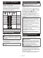
1
2
3
Fig.1
1
Fig.2
1
2
Fig.3
1
Fig.4
1
Fig.5
1
Fig.6
AB
1
Fig.7
1
2
3
4
5
Fig.8
2

1
2
Fig.9
2
3
1
Fig.10
A
Fig.11
1
2
Fig.12
2
1
3
Fig.13
1
2
3
Fig.14
Fig.15
3

4ENGLISH
ENGLISH (Original instructions)
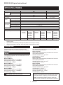
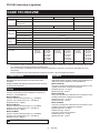
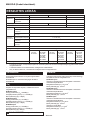
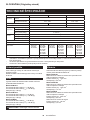
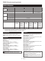
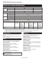
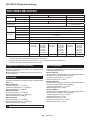
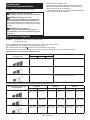
SPECIFICATIONS
Model: DTW1001 DTW1002 DTW800
Fastening
capacities
Standard bolt M12 - M30 M12 - M24
High tensile bolt M10 - M24 M10 - M22
Square drive 19 mm 12.7 mm –
Drive shank –11.1 mm Hex.
No load
speed
Impact mode (Hard) 0 - 1,800 min-1
Impact mode (Medium) 0 - 1,000 min-1
Impact mode (Soft) 0 - 900 min-1
Impacts
per minute
Impact mode (Hard) 0 - 2,200 min-1
Impact mode (Medium) 0 - 2,000 min-1
Impact mode (Soft) 0 - 1,800 min-1
Overall length 229 mm
Rated voltage D.C. 18 V
Battery cartridge BL1815N,
BL1820,
BL1820B
BL1830,
BL1830B,
BL1840,
BL1840B,
BL1850,
BL1850B,
BL1860B
BL1815N,
BL1820,
BL1820B
BL1830,
BL1830B,
BL1840,
BL1840B,
BL1850,
BL1850B,
BL1860B
BL1815N,
BL1820,
BL1820B
BL1830,
BL1830B,
BL1840,
BL1840B,
BL1850,
BL1850B,
BL1860B
Net weight 3.4 kg 3.7 kg 3.3 kg 3.6 kg 3.4 kg 3.7 kg
• Duetoourcontinuingprogramofresearchanddevelopment,thespecicationshereinaresubjecttochange
without notice.
• Specicationsandbatterycartridgemaydifferfromcountrytocountry.
• Weight, with battery cartridge, according to EPTA-Procedure 01/2003
Intended use
The tool is intended for fastening bolts and nuts.
Model DTW800: The tool is also intended for drilling
into wood.
Noise
The typical A-weighted noise level determined accord-
ing to EN60745:
Model DTW1001
Sound pressure level (LpA) : 98 dB(A)
Sound power level (LWA) : 109 dB (A)
Uncertainty (K) : 3 dB(A)
Model DTW1002
Sound pressure level (LpA) : 97 dB(A)
Sound power level (LWA) : 108 dB (A)
Uncertainty (K) : 3 dB(A)
Model DTW800
Sound pressure level (LpA) : 95 dB(A)
Sound power level (LWA) : 106 dB (A)
Uncertainty (K) : 3dB(A)
WARNING: Wear ear protection.
Vibration
The vibration total value (tri-axial vector sum) deter-
mined according to EN60745:
Model DTW1001
Work mode: impact tightening of fasteners of the maxi-
mum capacity of the tool
Vibration emission (ah) : 15.5 m/s2
Uncertainty (K) : 2.0 m/s2
Model DTW1002
Work mode: impact tightening of fasteners of the maxi-
mum capacity of the tool
Vibration emission (ah) : 18.0 m/s2
Uncertainty (K) : 1.5 m/s2
Model DTW800
Work mode: impact tightening of fasteners of the maxi-
mum capacity of the tool
Vibration emission (ah) : 24.0 m/s2
Uncertainty (K) : 2.0 m/s2
Work mode: drilling into wood
Vibration emission (ah) : 7.0 m/s2
Uncertainty (K) : 1.5 m/s2
NOTE:
The declared vibration emission value has been
measured in accordance with the standard test method
and may be used for comparing one tool with another.
NOTE:
The declared vibration emission value may
also be used in a preliminary assessment of exposure.

5ENGLISH
WARNING:
The vibration emission during actual
use of the power tool can differ from the declared emission
value depending on the ways in which the tool is used.
WARNING: Be sure to identify safety measures
to protect the operator that are based on an estima-
tion of exposure in the actual conditions of use (taking
account of all parts of the operating cycle such as
the times when the tool is switched off and when it is
running idle in addition to the trigger time).
EC Declaration of Conformity
For European countries only
Makita declares that the following Machine(s):
Designation of Machine: Cordless Impact Wrench
Model No./ Type: DTW1001, DTW1002, DTW800
Conforms to the following European Directives:
2006/42/EC
They are manufactured in accordance with the following
standard or standardized documents: EN60745
Thetechnicalleinaccordancewith2006/42/ECis
available from:
Makita, Jan-Baptist Vinkstraat 2, 3070, Belgium
13.5.2015
Yasushi Fukaya
Director
Makita, Jan-Baptist Vinkstraat 2, 3070, Belgium
General power tool safety warnings
WARNING:
Read all safety warnings and all
instructions. Failure to follow the warnings and instruc-
tionsmayresultinelectricshock,reand/orseriousinjury.
Save all warnings and instruc-
tions for future reference.
The term "power tool" in the warnings refers to your
mains-operated (corded) power tool or battery-operated
(cordless) power tool.
Cordless impact wrench safety
warnings
1. Hold power tool by insulated gripping sur-
faces, when performing an operation where
the fastener may contact hidden wiring.
Fasteners contacting a "live" wire may make
exposed metal parts of the power tool "live" and
could give the operator an electric shock.
2. Wear ear protectors.
3. Check the impact socket carefully for wear,
cracks or damage before installation.
4. Hold the tool rmly.
5. Always be sure you have a rm footing.
Be sure no one is below when using the tool in
high locations.
6. The proper fastening torque may differ
depending upon the kind or size of the bolt.
Check the torque with a torque wrench.
7. Use auxiliary handle(s), if supplied with the
tool.Lossofcontrolcancausepersonalinjury.
8. Hold power tool by insulated gripping sur-
faces, when performing an operation where
the cutting accessory may contact hidden
wiring. Cutting accessory contacting a "live"
wire may make exposed metal parts of the power
tool "live" and could give the operator an electric
shock.
9. Keep hands away from rotating parts.
10. Do not touch the drill bit or the workpiece
immediately after operation; they may be
extremely hot and could burn your skin.
11. Some material contains chemicals which may
be toxic. Take caution to prevent dust inhala-
tion and skin contact. Follow material supplier
safety data.
SAVE THESE INSTRUCTIONS.
WARNING: DO NOT let comfort or familiarity
with product (gained from repeated use) replace
strict adherence to safety rules for the subject
product.
MISUSE or failure to follow the safety rules stated
in this instruction manual may cause serious
personal injury.
Important safety instructions for
battery cartridge
1. Before using battery cartridge, read all instruc-
tions and cautionary markings on (1) battery
charger, (2) battery, and (3) product using
battery.
2. Do not disassemble battery cartridge.
3. If operating time has become excessively
shorter, stop operating immediately. It may
result in a risk of overheating, possible burns
and even an explosion.
4. If electrolyte gets into your eyes, rinse them
out with clear water and seek medical atten-
tion right away. It may result in loss of your
eyesight.
5. Do not short the battery cartridge:
(1) Do not touch the terminals with any con-
ductive material.
(2) Avoid storing battery cartridge in a con-
tainer with other metal objects such as
nails, coins, etc.
(3) Do not expose battery cartridge to water
or rain.
A battery short can cause a large current
ow, overheating, possible burns and even a
breakdown.
6. Do not store the tool and battery cartridge in
locations where the temperature may reach or
exceed 50 °C (122 °F).
7. Do not incinerate the battery cartridge even if
it is severely damaged or is completely worn
out. The battery cartridge can explode in a re.
8. Be careful not to drop or strike battery.
9. Do not use a damaged battery.

6ENGLISH
10. The contained lithium-ion batteries are subject
to the Dangerous Goods Legislation require-
ments.
For commercial transports e.g. by third parties,
forwarding agents, special requirement on pack-
aging and labeling must be observed.
For preparation of the item being shipped, consult-
ing an expert for hazardous material is required.
Please also observe possibly more detailed
national regulations.
Tape or mask off open contacts and pack up the
battery in such a manner that it cannot move
around in the packaging.
11. Follow your local regulations relating to dis-
posal of battery.
SAVE THESE INSTRUCTIONS.
CAUTION: Only use genuine Makita batteries.
Use of non-genuine Makita batteries, or batteries that
have been altered, may result in the battery bursting
causingres,personalinjuryanddamage.Itwill
also void the Makita warranty for the Makita tool and
charger.
Tips for maintaining maximum
battery life
1. Charge the battery cartridge before completely
discharged. Always stop tool operation and
charge the battery cartridge when you notice
less tool power.
2. Never recharge a fully charged battery car-
tridge. Overcharging shortens the battery
service life.
3. Charge the battery cartridge with room tem-
perature at 10 °C - 40 °C (50 °F - 104 °F). Let
a hot battery cartridge cool down before
charging it.
4. Charge the battery cartridge if you do not use
it for a long period (more than six months).
FUNCTIONAL
DESCRIPTION
CAUTION: Always be sure that the tool is
switched off and the battery cartridge is removed
before adjusting or checking function on the tool.
Installing or removing battery
cartridge
CAUTION: Always switch off the tool before
installing or removing of the battery cartridge.
CAUTION: Hold the tool and the battery car-
tridge rmly when installing or removing battery
cartridge. Failure to hold the tool and the battery
cartridgermlymaycausethemtoslipoffyourhands
and result in damage to the tool and battery cartridge
andapersonalinjury.
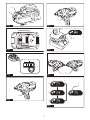
►Fig.1: 1. Red indicator 2. Button 3. Battery cartridge
To remove the battery cartridge, slide it from the tool
while sliding the button on the front of the cartridge.
To install the battery cartridge, align the tongue on the
battery cartridge with the groove in the housing and slip
it into place. Insert it all the way until it locks in place
with a little click. If you can see the red indicator on the
upper side of the button, it is not locked completely.
CAUTION: Always install the battery cartridge
fully until the red indicator cannot be seen. If not,
itmayaccidentallyfalloutofthetool,causinginjuryto
you or someone around you.
CAUTION: Do not install the battery cartridge
forcibly. If the cartridge does not slide in easily, it is
not being inserted correctly.
Battery protection system
Lithium-ion battery with star marking
►Fig.2: 1. Star marking
Lithium-ion batteries with a star marking are equipped
with a protection system. This system automatically
cuts off power to the tool to extend battery life.
The tool will automatically stop during operation if the
tool and/or battery are placed under one of the following
conditions:
Overloaded:
The tool is operated in a manner that causes it to draw
an abnormally high current.
In this situation, turn the tool off and stop the application
that caused the tool to become overloaded. Then turn
the tool on to restart.
If the tool does not start, the battery is overheated. In
this situation, let the battery cool before turning the tool
on again.
Low battery voltage:
The remaining battery capacity is too low and the tool
will not operate. In this situation, remove and recharge
the battery.

7ENGLISH
Indicating the remaining battery
capacity
Only for battery cartridges with "B" at the end of the
model number
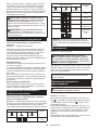
►Fig.3: 1. Indicator lamps 2. Check button
Press the check button on the battery cartridge to indi-
cate the remaining battery capacity. The indicator lamps
light up for few seconds.
Indicator lamps Remaining
capacity
Lighted Off Blinking
75% to 100%
50% to 75%
25% to 50%
0% to 25%
Charge the
battery.
The battery
may have
malfunctioned.
NOTE: Depending on the conditions of use and the
ambient temperature, the indication may differ slightly
from the actual capacity.
Switch action
►Fig.4: 1. Switch trigger
CAUTION: Before installing the battery car-
tridge into the tool, always check to see that the
switch trigger actuates properly and returns to
the "OFF" position when released.
To start the tool, simply pull the switch trigger. Tool
speed is increased by increasing pressure on the switch
trigger. Release the switch trigger to stop.
NOTE: The tool automatically stops if you keep pull-
ing the switch trigger for about 6 minutes.
Lighting up the front lamp
CAUTION: Do not look in the light or see the
source of light directly.
►Fig.5: 1. Lamp
►Fig.6: 1. Button
To turn on the lamp status, press the button for
one second. To turn off the lamp status, press the but-
ton for one second again.
With the lamp status ON, pull the switch trigger to turn
on the lamp. To turn off, release it. The lamp goes out
approximately 10 seconds after releasing the switch
trigger.
With the lamp status OFF, the lamp does not turn on
even if pulling the trigger.
NOTE:Toconrmthelampstatus,pullthetrigger.
When the lamp lights up by pulling the switch trigger,
the lamp status is ON. When the lamp does not come
on, the lamp status is OFF.
NOTE:Whenthetoolisoverheated,thelightashes
for one minute, and then the LED display goes off. In
this case, cool down the tool before operating again.
NOTE: Use a dry cloth to wipe the dirt off the lens of
the lamp. Be careful not to scratch the lens of lamp, or
it may lower the illumination.
NOTE: While pulling the switch trigger, the lamp
status cannot be changed.
NOTE: For approximately 10 seconds after releasing
the switch trigger, the lamp status can be changed.
Reversing switch action
►Fig.7: 1. Reversing switch lever
CAUTION: Always check the direction of
rotation before operation.
CAUTION: Use the reversing switch only after
the tool comes to a complete stop. Changing the
direction of rotation before the tool stops may dam-
age the tool.
CAUTION: When not operating the tool,
always set the reversing switch lever to the neu-
tral position.
This tool has a reversing switch to change the direction
of rotation. Depress the reversing switch lever from the
A side for clockwise rotation or from the B side for coun-
terclockwise rotation.
When the reversing switch lever is in the neutral posi-
tion, the switch trigger cannot be pulled.

8ENGLISH
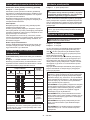
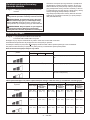
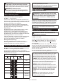
Changing the impact force
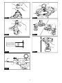
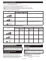
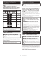
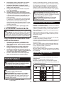
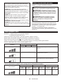
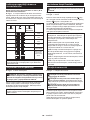
►Fig.8: 1. Changed in three steps 2. Hard 3. Medium
4. Soft 5. Button
You can change the impact in three steps: hard, medium and soft mode.
This allows a tightening suitable to the work.
Every time the button is pressed, the number of blows changes in three steps.
For approximately one minute after releasing the switch trigger, the impact force can be changed.
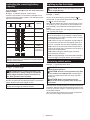
Specications of each impact force grade
Impact force grade displayed on
panel
Maximum blows Application
DTW1001 DTW1002 DTW800
Hard 2,200 min-1 (/min) Tightening when force and speed are desired.
Medium 2,000 min-1 (/min) Tightening when you need good controlled power.
Soft 1,800 min-1 (/min) Tighteningwhenyouneedneadjustmentwith
small diameter bolt.
Impact force/bolt size corresponding chart (reference)
Impact force grade displayed on
panel
DTW1001 DTW1002 DTW800
Standard bolt High tensile
bolt
Standard bolt High tensile
bolt
Standard bolt High tensile
bolt
Hard M20 - M30
(3/4″-1-1/4″)
M16 - M24
(5/8″-1″)
M20 - M30
(3/4″-1-1/4″)
M16 - M24
(5/8″-1″)
M20 - M24
(3/4″-1″)
M16 - M22
(5/8″-7/8″)
Medium M16 - M24
(5/8″-1″)
M12 - M20
(1/2″-3/4″)
M16 - M24
(5/8″-1″)
M12 - M20
(1/2″-3/4″)
M14 - M20
(9/16″-3/4″)
M10 - M16
(3/8″-5/8″)
Soft M12 - M20
(1/2″-3/4″)
M10 - M16
(3/8″-5/8″)
M12 - M20
(1/2″-3/4″)
M10 - M16
(3/8″-5/8″)
M12 - M16
(1/2″-5/8″)
M10 - M12
(3/8″-1/2″)
ASSEMBLY
CAUTION: Always be sure that the tool is
switched off and the battery cartridge is removed
before carrying out any work on the tool.
Selecting correct impact socket
Always use the correct size impact socket for bolts and
nuts. An incorrect size impact socket will result in inac-
curate and inconsistent fastening torque and/or damage
to the bolt or nut.
Installing or removing impact socket
Only for Model DTW1001,DTW1002 (optional
accessory)
CAUTION: Make sure that the impact socket
and the mounting portion are not damaged before
installing the impact socket.
For impact socket without O-ring and pin
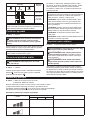
►Fig.9: 1. Impact socket 2. Square drive
Align the square of the impact socket with the square
drive and push the impact socket onto the square drive
until it locks into place. Tap it lightly if required.
To remove the impact socket, simply pull it off.

9ENGLISH
For impact socket with O-ring
and pin
Only for Model DTW1001
►Fig.10: 1. Impact socket 2. O-ring 3. Pin
Move the O-ring out of the groove in the impact socket
and remove the pin from the impact socket. Fit the
impact socket onto the square drive so that the hole in
the impact socket is aligned with the hole in the square
drive.
Insert the pin through the hole in the impact socket and
square drive. Then return the O-ring to the original posi-
tion in the impact socket groove to retain the pin.
To remove the impact socket, follow the installation
procedures in reverse.
Installing or removing drill bit/
socket adapter
Only for Model DTW800 (optional accessory)
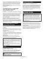
►Fig.11
A=11.2 mm
Useonlythedrillbit/socketadaptershowninthegure.
Do not use any other drill bit/socket adapter.
►Fig.12: 1. Drill bit 2. Sleeve
To install the drill bit, pull the sleeve in the direction of
the arrow and insert the drill bit into the sleeve as far as
it will go.
Then release the sleeve to secure the drill bit.
To remove the drill bit, pull the sleeve in the direction of
the arrow and pull the drill bit out.
NOTE: If the drill bit is not inserted deep enough into
the sleeve, the sleeve will not return to its original
position and the drill bit will not be secured. In this
case, try re-inserting the drill bit according to the
instructions above.
NOTE: After inserting the drill bit, make sure that it is
rmlysecured.Ifitcomesout,donotuseit.
Ring
Only for Model DTW800
►Fig.13: 1. Bracket 2. Ring 3. Screws
The ring is convenient for hanging the tool with hoist.
First, place the rope through the ring. Then hang the
tool up to the air with hoist.
CAUTION: Before using the ring, always
make sure that the bracket and ring are secured
and not damaged.
Installing hook
►Fig.14: 1. Groove 2. Hook 3. Screw
The hook is convenient for temporarily hanging the tool.
This can be installed on either side of the tool. To install
the hook, insert it into a groove in the tool housing
on either side and then secure it with two screws. To
remove, loosen the screws and then take it out.
OPERATION
CAUTION: Always insert the battery cartridge
all the way until it locks in place. If you can see the
red indicator on the upper side of the button, it is not
locked completely. Insert it fully until the red indicator
cannot be seen. If not, it may accidentally fall out of
thetool,causinginjurytoyouorsomeonearound
you.
►Fig.15
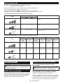
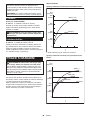
Holdthetoolrmlyandplacetheimpactsocketover
the bolt or nut. Turn the tool on and fasten for the proper
fastening time.
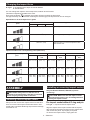
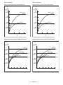
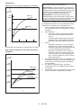
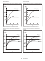
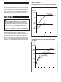
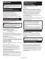
The proper fastening torque may differ depending upon
the kind or size of the bolt, the material of the workpiece
to be fastened, etc. The relation between fastening
torqueandfasteningtimeisshowninthegures.

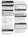
10 ENGLISH
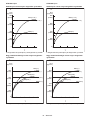
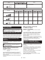
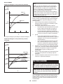
Model DTW1001
Proper fastening torque for standard bolt
1
2
N•m
(kgf•cm)
800
600
400
200
(2040)
(4080)
(6120)
(8160)
1023
0
M24(1″)
M24(1″)
M30(1-1/4″)
M30(1-1/4″)
1. Fastening time (second) 2. Fastening torque
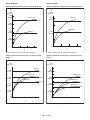
Proper fastening torque for high tensile bolt
1023456
0
800
600
400
200
(2040)
(4080)
(6120)
(8160)
N•m
(kgf•cm)
2
1
M24(1″)
M24(1″)
M22(7/8″)
M22(7/8″)
M20(3/4″)
M20(3/4″)
1. Fastening time (second) 2. Fastening torque
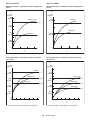
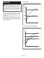
Model DTW1002
Proper fastening torque for standard bolt
1
2
N•m
(kgf•cm)
800
600
400
200
(2040)
(4080)
(6120)
(8160)
1023
0
M24(1″)
M24(1″)
M30(1-1/4″)
M30(1-1/4″)
1. Fastening time (second) 2. Fastening torque
Proper fastening torque for high tensile bolt
1023456
0
800
600
400
200
(2040)
(4080)
(6120)
(8160)
N•m
(kgf•cm)
2
1
M24(1″)
M24(1″)
M22(7/8″)
M22(7/8″)
M20(3/4″)
M20(3/4″)
1. Fastening time (second) 2. Fastening torque

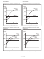
11 ENGLISH
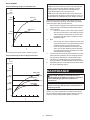
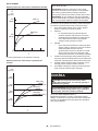
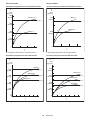
Model DTW800
Proper fastening torque for standard bolt
N•m
(kgf•cm)
1
1
02
3
0
400
200
(2040)
(4080)
M20(3/4″)
M20(3/4″)
M24(1″)
M24(1″)
2
1. Fastening time (second) 2. Fastening torque
Proper fastening torque for high tensile bolt
1023456
0
800
600
400
200
(2040)
(4080)
(6120)
(8160)
N•m
(kgf•cm)
1
2
M22(7/8″)
M20(3/4″)
M20(3/4″)
M16(5/8″)
M16(5/8″)
M22(7/8″)
1. Fastening time (second) 2. Fastening torque
NOTE: Hold the tool pointed straight at the bolt or nut.
NOTE: Excessive fastening torque may damage the
bolt/nutorimpactsocket.Beforestartingyourjob,
always perform a test operation to determine the
proper fastening time for your bolt or nut.
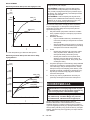
NOTE:
If the tool is operated continuously until the bat-
tery cartridge has discharged, allow the tool to rest for 15
minutes before proceeding with a fresh battery cartridge.
The fastening torque is affected by a wide variety of
factors including the following. After fastening, always
check the torque with a torque wrench.
1.
When the battery cartridge is discharged almost completely,
voltage will drop and the fastening torque will be reduced.
2. Impact socket
• Failure to use the correct size impact socket
will cause a reduction in the fastening torque.
• A worn impact socket (wear on the hex end
or square end) will cause a reduction in the
fastening torque.
3. Bolt
•
Eventhoughthetorquecoefcientandtheclass
of bolt are the same, the proper fastening torque
will differ according to the diameter of bolt.
• Even though the diameters of bolts are the
same, the proper fastening torque will differ
accordingtothetorquecoefcient,theclass
of bolt and the bolt length.
4.
Theuseoftheuniversaljointortheextensionbarsome-
what reduces the fastening force of the impact wrench.
Compensate by fastening for a longer period of time.
5.
The manner of holding the tool or the material of
driving position to be fastened will affect the torque.
6. Operating the tool at low speed will cause a reduc-
tion in the fastening torque.
MAINTENANCE
CAUTION: Always be sure that the tool is
switched off and the battery cartridge is removed
before attempting to perform inspection or
maintenance.
NOTICE: Never use gasoline, benzine, thinner,
alcohol or the like. Discoloration, deformation or
cracks may result.
To maintain product SAFETY and RELIABILITY,
repairs,anyothermaintenanceoradjustmentshould
be performed by Makita Authorized or Factory Service
Centers, always using Makita replacement parts.

12
OPTIONAL
ACCESSORIES
CAUTION: These accessories or attachments
are recommended for use with your Makita tool
specied in this manual. The use of any other
accessories or attachments might present a risk of
injurytopersons.Onlyuseaccessoryorattachment
for its stated purpose.
If you need any assistance for more details regard-
ing these accessories, ask your local Makita Service
Center.
• Impact socket
• Drill bits (only for Model DTW800)
• Extension bar
• Universaljoint
• Makita genuine battery and charger
NOTE: Some items in the list may be included in the
tool package as standard accessories. They may
differ from country to country.
ENGLISH

13
POLSKI (Instrukcja oryginalna)
DANE TECHNICZNE
Model: DTW1001 DTW1002 DTW800
Zakresy
dokręcania
Śrubazwykła M12–M30 M12–M24
Śrubaodużej
wytrzymałości
M10–M24 M10–M22
Zabierak kwadratowy 19 mm 12,7 mm –
Uchwyt gniazdowy –Sześciokątny11,1mm
Prędkość
bez
obciążenia
Trybudaru(dużasiła) 0–1 800 min-1
Trybudaru(średniasiła) 0–1 000 min-1
Trybudaru(małasiła) 0–900 min-1
Liczba
udarów na
minutę
Trybudaru(dużasiła) 0–2 200 min-1
Trybudaru(średniasiła) 0–2 000 min-1
Trybudaru(małasiła) 0–1 800 min-1
Długośćcałkowita 229 mm
Napięcieznamionowe Prądstały18V
Akumulator BL1815N,
BL1820,
BL1820B
BL1830,
BL1830B,
BL1840,
BL1840B,
BL1850,
BL1850B,
BL1860B
BL1815N,
BL1820,
BL1820B
BL1830,
BL1830B,
BL1840,
BL1840B,
BL1850,
BL1850B,
BL1860B
BL1815N,
BL1820,
BL1820B
BL1830,
BL1830B,
BL1840,
BL1840B,
BL1850,
BL1850B,
BL1860B
Ciężarnetto 3,4 kg 3,7 kg 3,3 kg 3,6 kg 3,4 kg 3,7 kg
• Wzwiązkuzestaleprowadzonymprzeznasząrmęprogramembadawczo-rozwojowymniniejszedanemogą
uleczmianombezwcześniejszegopowiadomienia.
• Winnychkrajachurządzeniemożemiećodmienneparametrytechniczneimożebyćwyposażonewinny
akumulator.
• MasaurządzeniawrazzakumulatoremobliczonazgodniezprocedurąEPTA01/2003
Przeznaczenie
Narzędziejestprzeznaczonedodokręcaniaśrubi
nakrętek.
ModelDTW800:Narzędziejestprzeznaczonerównież
do wiercenia w drewnie.
Hałas
TypowyrównoważnypoziomdźwiękuAokreślonyw
oparciuonormęEN60745:
Model DTW1001
Poziomciśnieniaakustycznego(LpA): 98 dB(A)
Poziommocyakustycznej(LWA): 109 dB (A)
Niepewność(K):3dB(A)
Model DTW1002
Poziomciśnieniaakustycznego(LpA): 97 dB(A)
Poziommocyakustycznej(LWA): 108 dB (A)
Niepewność(K):3dB(A)
Model DTW800
Poziomciśnieniaakustycznego(LpA): 95 dB(A)
Poziommocyakustycznej(LWA): 106 dB (A)
Niepewność(K):3dB(A)
OSTRZEŻENIE: Nosić ochronniki słuchu.
Drgania
Całkowitawartośćpoziomudrgań(sumawektoróww3
osiach)określonazgodnieznormąEN60745:
Model DTW1001
Trybpracy:dokręcanieudaroweśrubiwkrętówwmak-
symalnymzakresiemożliwościnarzędzia
Emisjadrgań(ah): 15,5 m/s2
Niepewność(K):2,0m/s2
Model DTW1002
Trybpracy:dokręcanieudaroweśrubiwkrętówwmak-
symalnymzakresiemożliwościnarzędzia
Emisjadrgań(ah): 18,0m/s2
Niepewność(K):1,5m/s2
Model DTW800
Trybpracy:dokręcanieudaroweśrubiwkrętówwmak-
symalnymzakresiemożliwościnarzędzia
Emisjadrgań(ah): 24,0m/s2
Niepewność(K):2,0m/s2
Tryb pracy: wiercenie w drewnie
Emisjadrgań(ah): 7,0m/s2
Niepewność(K):1,5m/s2
POLSKI

14 POLSKI
WSKAZÓWKA:Deklarowanawartośćwytwarzanych
drgańzostałazmierzonazgodniezestandardową
metodątestowąimożnająwykorzystaćdoporówny-
wanianarzędzi.
WSKAZÓWKA:Deklarowanąwartośćwytwarzanych
drgańmożnatakżewykorzystaćwewstępnejocenie
narażenia.
OSTRZEŻENIE: Drgania wytwarzane podczas
rzeczywistegoużytkowaniaelektronarzędziamogą
sięróżnićodwartoścideklarowanej,wzależnościod
sposobujegoużytkowania.
OSTRZEŻENIE: W oparciu o szacowane
narażeniewrzeczywistychwarunkachużytkowania
należyokreślićśrodkibezpieczeństwawceluochrony
operatora(uwzględniającwszystkieelementycyklu
działania,tj.czas,kiedynarzędziejestwyłączonei
kiedypracujenabiegujałowym,atakżeczas,kiedy
jestwłączone).
Deklaracja zgodności WE
Dotyczy tylko krajów europejskich
FirmaMakitaoświadcza,żeponiższeurządzenie(-a):
Oznaczenie maszyny: Akumulatorowy klucz udarowy
Model nr/typ: DTW1001, DTW1002, DTW800
Jestzgodnezwymogamiokreślonymiwnastępujących
dyrektywacheuropejskich:2006/42/EC
Jest/sąprodukowanezgodnieznastępującyminor-
mamilubdokumentaminormalizacyjnymi:EN60745
Dokumentacjatechnicznazgodnawwymaganiami
dyrektywy2006/42/ECjestdostępnaw:
Makita, Jan-Baptist Vinkstraat 2, 3070, Belgia
13.5.2015
Yasushi Fukaya
Dyrektor
Makita, Jan-Baptist Vinkstraat 2, 3070, Belgia
Ogólne zasady bezpiecznej
eksploatacji elektronarzędzi
OSTRZEŻENIE: Przeczytać wszystkie ostrze-
żenia bezpieczeństwa i wszystkie instrukcje.
Niezastosowaniesiędowspomnianychostrzeżeńi
instrukcjimożedoprowadzićdoporażeniaprądem
elektrycznym,pożarui/lubpoważnychobrażeńciała.
Wszystkie ostrzeżenia i instruk-
cje należy zachować do wykorzy-
stania w przyszłości.
Pojęcie„elektronarzędzie",występującewwymienio-
nychtuostrzeżeniach,odnosisiędoelektronarzędzia
zasilanegozsiecielektrycznej(zprzewodemzasilają-
cym)lubdoelektronarzędziaakumulatorowego(bez
przewoduzasilającego).
Ostrzeżenia dotyczące
bezpieczeństwa dla
akumulatorowego klucza
udarowego
1. Trzymać elektronarzędzie za izolowane
powierzchnie rękojeści podczas wykonywania
prac, przy których wkręcany wkręt lub śruba
mogą dotknąć niewidocznej instalacji elek-
trycznej.Zetknięciewkrętulubśrubyzprzewo-
demelektrycznymznajdującymsiępodnapięciem
spowoduje,żeodsłonięteelementymetalowe
narzędziarównieżznajdąsiępodnapięciem,gro-
żącporażeniemoperatoraprądemelektrycznym.
2. Nosić ochronniki słuchu.
3. Przed przystąpieniem do pracy sprawdzić
dokładnie gniazdo udarowe pod kątem zuży-
cia, pęknięć lub uszkodzeń.
4. Narzędzie należy trzymać mocno i pewnie.
5. Podczas pracy należy zadbać o dobre oparcie
dla nóg.
W przypadku pracy na pewnej wysokości
upewnić się, że na dole nie przebywają żadne
osoby.
6. Odpowiedni moment dokręcania zależy od
rodzaju i wielkości śruby. Moment dokrę-
cenia należy sprawdzać za pomocą klucza
dynamometrycznego.
7. Używać narzędzia z uchwytami pomocniczymi,
jeśli zostały dostarczone wraz z nim. Utrata
kontrolimożespowodowaćobrażeniaciała.
8. Trzymać elektronarzędzie za izolowane
powierzchnie rękojeści podczas wykonywania
prac, przy których wiertło może dotknąć niewi-
docznej instalacji elektrycznej.Zetknięciewier-
tłazprzewodemelektrycznymznajdującymsię
podnapięciemmożespowodować,żeodsłonięte
elementymetaloweelektronarzędziarównież
znajdąsiępodnapięciem,grożącporażeniem
operatoraprądemelektrycznym.
9. Trzymać ręce z dala od części obrotowych.
10. Nie dotykać wiertła ani części obrabianej od
razu po zakończeniu danej operacji; mogą one
być bardzo gorące i spowodować oparzenie
skóry.
11. Niektóre materiały zawierają substancje
chemiczne, które mogą być toksyczne.
Unikać wdychania pyłu i kontaktu ze skórą.
Przestrzegać przepisów bezpieczeństwa poda-
nych przez dostawcę materiałów.
ZACHOWAĆ NINIEJSZE
INSTRUKCJE.
OSTRZEŻENIE: NIE WOLNO pozwolić, aby
wygoda lub rutyna (nabyta w wyniku wielokrot-
nego używania urządzenia) zastąpiły ścisłe prze-
strzeganie zasad bezpieczeństwa obsługi.
NIEWŁAŚCIWE UŻYTKOWANIE narzędzia lub
niestosowanie się do zasad bezpieczeństwa
podanych w niniejszej instrukcji obsługi może
prowadzić do poważnych obrażeń ciała.

15 POLSKI
Ważne zasady bezpieczeństwa
dotyczące akumulatora
1.
Przed użyciem akumulatora zapoznać się ze
wszystkimi instrukcjami i znakami ostrzegaw-
czymi na (1) ładowarce, (2) akumulatorze i (3)
produkcie, w którym będzie używany akumulator.
2. Akumulatora nie wolno rozbierać.
3. Jeśli czas działania uległ znacznemu skróce-
niu, należy natychmiast przerwać pracę. Może
bowiem dojść do przegrzania, ewentualnych
poparzeń, a nawet eksplozji.
4.
W przypadku przedostania się elektrolitu do oczu,
przemyć je czystą wodą i niezwłocznie uzyskać pomoc
lekarską. Może on bowiem spowodować utratę wzroku.
5. Nie doprowadzać do zwarcia akumulatora:
(1) Nie dotykać styków materiałami przewo-
dzącymi prąd.
(2) Unikać przechowywania akumulatora w
pojemniku z metalowymi przedmiotami,
takimi jak gwoździe, monety itp.
(3)
Chronić akumulator przed deszczem lub wodą.
Zwarcie prowadzi do przepływu prądu elek-
trycznego o dużym natężeniu i przegrzania
akumulatora, co w konsekwencji może grozić
poparzeniami a nawet awarią urządzenia.
6. Narzędzia i akumulatora nie wolno przecho-
wywać w miejscach, w których temperatura
osiąga bądź przekracza 50°C (122°F).
7. Akumulatorów nie wolno spalać, również tych
poważnie uszkodzonych lub całkowicie zuży-
tych. Akumulator może eksplodować w ogniu.
8.
Chronić akumulator przed upadkiem i uderzeniami.
9. Nie wolno używać uszkodzonego akumulatora.
10.
Stanowiące wyposażenie akumulatory litowo-jonowe
podlegają przepisom dotyczącym produktów niebez-
piecznych.
Napotrzebytransportukomercyjnego,np.świadczonego
przezrmytrzecieczyspedycyjne,należyprzestrzegać
specjalnychwymagańwzakresiepakowaniaioznaczania
etykietami.
Przygotowanieproduktudowysyłkiwymagaskonsultowania
sięzespecjalistąds.materiałówniebezpiecznych.Należy
takżeprzestrzegaćprzepisówkrajowych,któremogąbyć
bardziejszczegółowe.
Zakleićtaśmąlubzaślepićotwartestykiakumulatoraoraz
zabezpieczyćgo,abyniemógłsięprzesuwaćwopakowaniu.
11. Postępować zgodnie z przepisami lokalnymi
dotyczącymi usuwania akumulatorów.
ZACHOWAĆ NINIEJSZE
INSTRUKCJE.
PRZESTROGA: Używać wyłącznie oryginal-
nych akumulatorów rmy Makita.Używanienie-
oryginalnychakumulatorówrminnychniżMakitalub
akumulatorów,którezostałyzmodykowane,może
spowodowaćwybuchakumulatoraipożar,obrażenia
ciałaorazzniszczeniemienia.Stanowitorównież
naruszeniewarunkówgwarancjirmyMakitadoty-
czącychnarzędziaiładowarki.
Wskazówki dotyczące zacho-
wania maksymalnej trwałości
akumulatora
1. Akumulator należy naładować zanim zostanie
do końca rozładowany. Po zauważeniu spadek
mocy narzędzia należy przerwać pracę i nała-
dować akumulator.
2. Nie wolno ładować powtórnie w pełni nałado-
wanego akumulatora. Przeładowanie akumula-
tora skraca jego trwałość.
3. Akumulator należy ładować w temperaturze
pokojowej w przedziale 10–40°C (50–104°F). W
przypadku gorącego akumulatora przed przy-
stąpieniem do ładowania należy poczekać, aż
ostygnie.
4. Akumulatory niklowo-wodorkowe należy nała-
dować po okresie długiego nieużytkowania
(dłuższego niż sześć miesięcy).
OPIS DZIAŁANIA
PRZESTROGA: Przed przystąpieniem do regu-
lacji lub przeglądu narzędzia upewnić się, że jest
ono wyłączone, a akumulator został wyjęty.
Wkładanie i wyjmowanie
akumulatora
PRZESTROGA: Przed włożeniem lub wyjęciem
akumulatora należy zawsze wyłączyć narzędzie.
PRZESTROGA: Podczas wkładania lub wyjmo-
wania akumulatora należy mocno trzymać narzę-
dzie i akumulator.Wprzeciwnymraziemogąsięone
wyślizgnąćzrąk,powodującuszkodzenienarzędzia
lubakumulatoraiobrażeniaciała.
►Rys.1: 1.Czerwonywskaźnik2. Przycisk
3. Akumulator
Abywyjąćakumulator,przesuńprzyciskznajdującysię
wprzedniejjegoczęściiwysuńakumulator.
Abywłożyćakumulator,wyrównajwystępnaakumu-
latorzezrowkiemwobudowieiwsuńgonaswoje
miejsce.Akumulatornależywsunąćdooporu,ażsię
zatrzaśnienamiejscu,cojestsygnalizowanedelikat-
nymkliknięciem.Jeśliwgórnejczęściprzyciskujest
widocznyczerwonywskaźnik,akumulatorniezostał
całkowiciezatrzaśnięty.
PRZESTROGA: Akumulator należy włożyć
do końca, tak aby czerwony wskaźnik nie był
widoczny.Wprzeciwnymraziemożeprzypadkowo
wypaśćznarzędzia,powodującobrażeniaoperatora
lub osób postronnych.
PRZESTROGA: Nie wkładać akumulatora na
siłę.Jeśliakumulatorniedajesięswobodniewsunąć,
oznaczato,żezostałwłożonynieprawidłowo.

16 POLSKI
Układ zabezpieczenia akumulatora
Akumulator litowo-jonowy oznaczony gwiazdką
►Rys.2: 1. Znak gwiazdki
Akumulatorylitowo-jonowezeznakiemgwiazdkisą
wyposażonewukładzabezpieczający.Układtenauto-
matycznieodcinazasilanienarzędziawceluwydłuże-
niażywotnościakumulatora.
Narzędziezostanieautomatyczniezatrzymanepod-
czaspracywnastępującychsytuacjachzwiązanychz
narzędziem/akumulatorem:
Przeciążenie:
Narzędziepracujewsposób,którypowodujepobór
nadmierniewysokiegoprądu.
Wtakiejsytuacjinależywyłączyćnarzędzieizaprze-
staćwykonywaniaczynnościpowodującejprzeciążenie
narzędzia.Następnienależywłączyćnarzędziewcelu
jegoponownegouruchomienia.
Jeślinarzędzienieuruchomisię,oznaczato,żeaku-
mulatorjestprzegrzany.Wtakiejsytuacji,przedponow-
nymuruchomieniemnarzędzianależyodczekać,aż
akumulator ostygnie.
Niskie napięcie akumulatora:
Poziomnaładowaniaakumulatorajestzbytniski,aby
narzędziemogłopracować.Wtakiejsytuacjinależy
wyjąćakumulatorigonaładować.
Wskazanie stanu naładowania
akumulatora
Tylko akumulatory oznaczone literą „B” na końcu
model
►Rys.3: 1.Lampkiwskaźnika2. Przycisk kontrolny
Nacisnąćprzyciskkontrolnynaakumulatorzewcelu
wyświetleniastanunaładowaniaakumulatora.Lampki
wskaźnikazaświecąsięprzezkilkasekund.
Lampki wskaźnika Pozostała
energia
akumulatora
Świeci się Wyłączony Miga
75–100%
50–75%
25–50%
0–25%
Naładować
akumulator.
Akumulator
możenie
działać
poprawnie.
WSKAZÓWKA:Zależnieodwarunkówużytkowania
itemperaturyotoczenia,wskazywanypoziommoże
nieznaczniesięróżnićodrzeczywistegostanunała-
dowania akumulatora.
Działanie przełącznika
►Rys.4: 1.Spustprzełącznika
PRZESTROGA: Przed włożeniem akumulatora
do narzędzia należy zawsze sprawdzić, czy spust
przełącznika działa prawidłowo i czy powraca do
położenia wyłączenia po jego zwolnieniu.
Wceluuruchomienianarzędziawystarczypociągnąć
spustprzełącznika.Prędkośćnarzędziazwiększasię
wrazzezwiększaniemnaciskunaspustprzełącznika.
Wceluzatrzymaniaurządzenianależyzwolnićspust
przełącznika.
WSKAZÓWKA:Narzędziezatrzymasięautoma-
tycznie,gdyspustprzełącznikapozostaniewciśnięty
przezokoło6min.
Włączanie lampki czołowej
PRZESTROGA: Nie patrzeć na światło ani
bezpośrednio na źródło światła.
►Rys.5: 1. Lampka
►Rys.6: 1. Przycisk
Wceluwłączeniatrybudziałanialampkioświetlenia
nacisnąćiprzytrzymaćprzezjednąsekundęprzy-
cisk .Wceluwyłączeniatrybudziałanialampki
oświetleniaponownienacisnąćiprzytrzymaćprzez
jednąsekundęprzycisk .
Gdytrybdziałanialampkioświetleniajestwłączony,
lampkaoświetleniawłączasiępopociągnięciuspu-
stuprzełącznika.Abywyłączyćlampkęoświetlenia,
należyzwolnićspustprzełącznika.Lampkaoświetle-
niawyłączasiępookoło10sodzwolnieniaspustu
przełącznika.
Gdytrybdziałanialampkioświetleniajestwyłączony,
lampkaoświetlenianiewłączasiępopociągnięciu
spustuprzełącznika.
WSKAZÓWKA:Abysprawdzićtrybdziałanialampki
oświetlenia,należypociągnąćzaspustprzełącznika.
Jeślipopociągnięciuzaspustprzełącznikalampka
oświetleniawłączysię,oznaczato,żetrybdziałania
lampkioświetleniajestwłączony.Jeślilampkaoświe-
tlenianiewłączysię,oznaczato,żetrybdziałania
lampkioświetleniajestwyłączony.
WSKAZÓWKA:Wprzypadkuprzegrzanianarzędzia,
lampkabędziemigałaprzezjednąminutę,anastęp-
niewyświetlaczLEDzostaniewyłączony.Wtakiej
sytuacjinależypoczekać,ażnarzędzieostygnie
przeddalszymjegoużytkowaniem.
WSKAZÓWKA:Abyusunąćzabrudzeniazklosza
lampki,należyużyćsuchejszmatki.Uważać,abynie
zarysowaćkloszalampki,gdyżmożetozmniejszyć
natężenieoświetlenia.
WSKAZÓWKA:Gdyspustprzełącznikajestnaci-
śnięty,niemożnazmienićtrybudziałanialampki
oświetlenia.
WSKAZÓWKA:Trybdziałanialampkioświetlenia
możnazmienićpook.10sodzwolnieniaspustu
przełącznika.

17 POLSKI
Działanie przełącznika zmiany
kierunku obrotów
►Rys.7: 1.Dźwigniaprzełącznikazmianykierunku
obrotów
PRZESTROGA:
Przed przystąpieniem do pracy
należy zawsze sprawdzić ustawiony kierunek obrotów.
PRZESTROGA:
Przełącznika zmiany kierunku
obrotów można użyć tylko po całkowitym zatrzy-
maniu narzędzia. Zmiana kierunku obrotów przed
zatrzymaniemsięnarzędziagrozijegouszkodzeniem.
PRZESTROGA:
Gdy narzędzie nie jest używane,
należy zawsze ustawić dźwignię przełącznika
zmiany kierunku obrotów w położeniu neutralnym.
Omawianenarzędziejestwyposażonewprzełącznik
umożliwiającyzmianękierunkuobrotów.Wceluuzy-
skaniaobrotówwprawąstronęnależywcisnąćdźwi-
gnięprzełącznikazmianykierunkuobrotówpostronie
A,natomiastabyuzyskaćobrotywlewąstronę,należy
wcisnąćdźwignięprzełącznikapostronieB.
Gdydźwigniaprzełącznikazmianykierunkuobrotów
znajdujesięwpołożeniuneutralnym,spustprzełącz-
nikajestzablokowany.
Zmiana siły udaru
►Rys.8: 1. Trzystopniowe ustawienie 2.Dużasiła
3.Średniasiła4.Małasiła5. Przycisk
Dostępnesątrzystopnieustawieniasiłyudaru:dużasiła,średniasiłaimałasiła.
Umożliwiadodopasowaniesiłydokręcaniadorzeczywistychpotrzeb.
Pokażdymnaciśnięciuprzycisku następujezmianaliczbaudarówspośródjednegoztrzechustawień.
Siłęudarumożnazmienićpoupływieok.jednejminutyodzwolnieniaspustuprzełącznika.
Dane techniczne dotyczące stopnia siły udaru
Stopień siły udaru wyświetlany na
panelu
Maksymalna częstotliwość udarów Zastosowanie
DTW1001 DTW1002 DTW800
Dużasiła 2 200 min-1 (/min) Dokręcanie,gdywymaganajestdużaszybkośći
siła.
Średniasiła 2 000 min-1 (/min) Dokręcanie,gdywymaganajestkontrolowanasiła.
Małasiła 1 800 min-1 (/min) Dokręcanie,gdywymaganajestdokładnaregulacja
dlaśrubomałejśrednicy.
Tabela przedstawiająca siłę udaru odpowiednią dla danego rozmiaru śruby (o charakterze informacyjnym)
Stopień siły udaru wyświetlany
na panelu
DTW1001 DTW1002 DTW800
Śruba zwykła Śruba o
dużej wytrzy-
małości
Śruba zwykła Śruba o
dużej wytrzy-
małości
Śruba zwykła Śruba o
dużej wytrzy-
małości
Dużasiła M20 - M30
(3/4″-1-1/4″)
M16 - M24
(5/8″-1″)
M20 - M30
(3/4″-1-1/4″)
M16 - M24
(5/8″-1″)
M20 - M24
(3/4″-1″)
M16 - M22
(5/8″-7/8″)
Średniasiła M16 - M24
(5/8″-1″)
M12 - M20
(1/2″-3/4″)
M16 - M24
(5/8″-1″)
M12 - M20
(1/2″-3/4″)
M14 - M20
(9/16″-3/4″)
M10 - M16
(3/8″-5/8″)
Małasiła M12 - M20
(1/2″-3/4″)
M10 - M16
(3/8″-5/8″)
M12 - M20
(1/2″-3/4″)
M10 - M16
(3/8″-5/8″)
M12 - M16
(1/2″-5/8″)
M10 - M12
(3/8″-1/2″)

18 POLSKI
MONTAŻ
PRZESTROGA: Przed przystąpieniem do prac
konserwacyjnych przy narzędziu upewnić się,
że jest ono wyłączone, a akumulator został wyjęty.
Wybór odpowiedniej nasadki
udarowej
Zawszeużywaćnasadekudarowychorozmiarzeodpo-
wiednimdorozmiaruśrubinakrętek.Nasadkaudarowa
oniewłaściwymrozmiarzeprowadzidoniedokładnego
inierównomiernegomomentudokręcaniai/lubuszko-
dzeniaśrubylubnakrętki.
Zakładanie i zdejmowanie nasadki
udarowej
Tylko dla modelu DTW1001,DTW1002 (osprzęt
dodatkowy)
PRZESTROGA: Przed założeniem nasadki
udarowej należy upewnić się, że sama nasadka
ani część mocująca nie są uszkodzone.
Nasadka udarowa bez pierścienia
O-ring i kołka
►Rys.9: 1. Nasadka udarowa 2. Zabierak
kwadratowy
Wyrównaćkwadratowyotwórnasadkiudarowejzzabie-
rakiemkwadratowymiwsunąćnasadkęnazabierak,
ażnasadkazablokujesięnaswoimmiejscu.Wrazie
potrzebylekkopuknąć.
Abyzdjąćnasadkęudarową,wystarczyjewyciągnąć.
Nasadka udarowa z pierścieniem
O-ring i kołkiem
Tylko dla modelu DTW1001
►Rys.10: 1. Nasadka udarowa 2.PierścieńO-ring
3.Kołek
WysunąćpierścieńO-ringrowkawnasadceudarowej
iwyjąćkołekznasadki.Założyćnasadkęudarowąna
zabieraku kwadratowym tak, aby otwór w nasadce
zrównałsięzotworemwzabieraku.
Wsunąćkołekwotwórwnasadceizabierakukwadra-
towym.NastępniezsunąćpierścieńO-ringdorowkaw
nasadceudarowej,abyzabezpieczyćkołek.
Abyzdjąćnasadkęudarową,należywykonaćczynności
proceduryzakładaniawodwrotnejkolejności.
Wkładanie i wyjmowanie wiertła /
adaptera do nasadek
Tylko dla modelu DTW800 (osprzęt dodatkowy)
►Rys.11
A = 11,2 mm
Należystosowaćwyłączniewiertła/adapterydonasa-
dekzkońcówkąpokazanąnarysunku.Niewolnouży-
waćinnychwierteł/adapterówdonasadek.
►Rys.12: 1.Wiertło2.Tuleja
Abywłożyćwiertło,pociągnąćzatulejęwkierunku
wskazanymstrzałkąiwsunąćwiertłojaknajgłębiejdo
tulei.
Następniezwolnićtuleję,abyzamocowaćwniejwiertło.
Abywyjąćwiertło,należypociągnąćtulejęwkierunku
wskazanymstrzałkąiwyciągnąćzniejwiertło.
WSKAZÓWKA:Jeśliwiertłoniezostaniewsunięte
wystarczającogłębokodotulei,tulejaniewrócido
swojegopierwotnegopołożenia,awiertłoniebędzie
dobrzezamocowane.Wtakimprzypadkunależy
spróbowaćponowniewłożyćwiertłozgodniezpowyż-
szymiinstrukcjami.
WSKAZÓWKA:Powsunięciuwiertłanależyupew-
nićsię,żejestonodobrzezamocowane.Jeślisię
wysuwa,nienależygoużywać.
Pierścień
Tylko dla modelu DTW800
►Rys.13: 1. Uchwyt 2.Pierścień3.Wkręty
Pierścieńjestprzydatnydozawieszenianarzędziana
podnośniku.Najpierwprzełożyćlinęprzezpierścień.
Następniepodwiesićnarzędzienapodnośniku.
PRZESTROGA: Przed użyciem pierścienia
należy upewnić się, że uchwyt i pierścień są
dobrze przymocowane i nie są uszkodzone.
Zamontowanie zaczepu
►Rys.14: 1. Rowek 2. Zaczep 3.Wkręt
Zaczepsłużydowygodnego,tymczasowegozawie-
szanianarzędzia.Możnagozamontowaćzjednejlub
zdrugiejstronynarzędzia.Abyzamontowaćzaczep,
należywsunąćgowrowekwobudowienarzędzia
znajdującysięzobustron,anastępnieprzykręcićgo
dwomawkrętami.Abywymontowaćzaczep,należy
odkręcićwkrętyiwyjąćzaczep.
OBSŁUGA
PRZESTROGA: Akumulator należy wsunąć
do oporu, aż wskoczy na swoje miejsce.Jeślijest
widocznyczerwonywskaźnikwgórnejczęściprzy-
cisku,akumulatorniezostałcałkowiciezatrzaśnięty.
Należygowsunąćdooporu,ażczerwonywskaźnik
przestaniebyćwidoczny.Wprzeciwnymraziemoże
onprzypadkowowypaśćznarzędzia,powodując
obrażeniaoperatoralubosóbpostronnych.
►Rys.15
Trzymaćmocnonarzędzieiumieścićnasadkęudarową
naśrubielubnakrętce.Włączyćnarzędzieidokręcać
przez odpowiedni czas.
Odpowiednimomentdokręceniazależyodrodzajui
rozmiaruśruby,materiałuelementu,doktóregowkręca
sięśrubęitp.Zależnośćmomentudokręceniaiczasu
dokręcaniapokazanonarysunkach.

19 POLSKI
Model DTW1001
Właściwy moment dokręcenia dla zwykłych śrub
1
2
N•m
(kgf•cm)
800
600
400
200
(2040)
(4080)
(6120)
(8160)
1023
0
M24(1″)
M24(1″)
M30(1-1/4″)
M30(1-1/4″)
1.Czasdokręcania(s)2.Momentdokręcenia
Właściwy moment dokręcenia dla śrub o dużej
wytrzymałości
1023456
0
800
600
400
200
(2040)
(4080)
(6120)
(8160)
N•m
(kgf•cm)
2
1
M24(1″)
M24(1″)
M22(7/8″)
M22(7/8″)
M20(3/4″)
M20(3/4″)
1.Czasdokręcania(s)2.Momentdokręcenia
Model DTW1002
Właściwy moment dokręcenia dla zwykłych śrub
1
2
N•m
(kgf•cm)
800
600
400
200
(2040)
(4080)
(6120)
(8160)
1023
0
M24(1″)
M24(1″)
M30(1-1/4″)
M30(1-1/4″)
1.Czasdokręcania(s)2.Momentdokręcenia
Właściwy moment dokręcenia dla śrub o dużej
wytrzymałości
1023456
0
800
600
400
200
(2040)
(4080)
(6120)
(8160)
N•m
(kgf•cm)
2
1
M24(1″)
M24(1″)
M22(7/8″)
M22(7/8″)
M20(3/4″)
M20(3/4″)
1.Czasdokręcania(s)2.Momentdokręcenia

20 POLSKI
Model DTW800
Właściwy moment dokręcenia dla zwykłych śrub
N•m
(kgf•cm)
1
1
02
3
0
400
200
(2040)
(4080)
M20(3/4″)
M20(3/4″)
M24(1″)
M24(1″)
2
1.Czasdokręcania(s)2.Momentdokręcenia
Właściwy moment dokręcenia dla śrub o dużej
wytrzymałości
1023456
0
800
600
400
200
(2040)
(4080)
(6120)
(8160)
N•m
(kgf•cm)
1
2
M22(7/8″)
M20(3/4″)
M20(3/4″)
M16(5/8″)
M16(5/8″)
M22(7/8″)
1.Czasdokręcania(s)2.Momentdokręcenia
WSKAZÓWKA:Narzędziepowinnobyćskierowane
nawprostśrubylubnakrętki.
WSKAZÓWKA:Nadmiernymomentdokręcania
możeuszkodzićśrubę/nakrętkęlubnasadkęuda-
rową.Przedprzystąpieniemdopracyzawszewyko-
naćpróbę,abyustalićwłaściwyczasdokręcaniadla
danejśrubylubnakrętki.
WSKAZÓWKA:Jeślinarzędziejestużywanebez
przerwyażdorozładowaniaakumulatora,należyje
odstawićna15minut,przedpodjęciempracyprzy
użyciuinnegonaładowanegoakumulatora.
Namomentdokręceniamawpływwieleczynników,
wtymnastępujące.Podokręceniunależyzawsze
sprawdzićmomentdokręceniazapomocąklucza
dynamometrycznego.
1. Gdyakumulatorjestprawiecałkowicierozłado-
wany,spadnienapięcieizmniejszysięmoment
dokręcenia.
2. Nasadka udarowa
• Użycienasadkiudarowejoniewłaściwym
rozmiarzepowodujezmniejszeniemomentu
dokręcania.
• Zużytanasadkaudarowa(zużycienakońcu
sześciokątnymlubkwadratowym)powoduje
zmniejszeniemomentudokręcania.
3. Śruba
• Nawetjeśliwspółczynnikmomentuiklasa
śrubysątakiesame,właściwymoment
dokręceniazależyodśrednicyśruby.
• Nawetjeśliśredniceśrubsątakiesame,
właściwymomentdokręceniazależyod
współczynnikamomentu,klasyśrubyoraz
oddługościśruby.
4. Używanieprzegubuuniwersalnegolubprzedłużki
możeniecozmniejszyćmomentdokręcaniaklu-
czaudarowego.Abytoskompensować,należy
dokręcaćśrubęlubnakrętkęprzezdłuższyczas.
5. Sposóbtrzymanianarzędzialubpołożenieprzy-
kręcanegomateriałumająwpływnawielkość
momentudokręcenia.
6. Pracaprzyniskichprędkościachobrotowych
powodujezmniejszeniemomentudokręcenia.
KONSERWACJA
PRZESTROGA: Przed przystąpieniem do prze-
glądu narzędzia lub jego konserwacji upewnić się,
że jest ono wyłączone, a akumulator wyjęty.
UWAGA: Nie stosować benzyny, rozpuszczalni-
ków, alkoholu itp. środków. Mogą one powodo-
wać odbarwienia, odkształcenia lub pęknięcia.
W celu zachowania odpowiedniego poziomu
BEZPIECZEŃSTWAiNIEZAWODNOŚCIproduktu
wszelkienaprawyiróżnegorodzajupracekonserwa-
cyjnelubregulacjepowinnybyćprzeprowadzaneprzez
autoryzowanylubfabrycznypunktserwisowynarzędzi
Makita,zawszezużyciemoryginalnychczęścizamien-
nych Makita.
Pagina se încarcă...
Pagina se încarcă...
Pagina se încarcă...
Pagina se încarcă...
Pagina se încarcă...
Pagina se încarcă...
Pagina se încarcă...
Pagina se încarcă...
Pagina se încarcă...
Pagina se încarcă...
Pagina se încarcă...
Pagina se încarcă...
Pagina se încarcă...
Pagina se încarcă...
Pagina se încarcă...
Pagina se încarcă...
Pagina se încarcă...
Pagina se încarcă...
Pagina se încarcă...
Pagina se încarcă...
Pagina se încarcă...
Pagina se încarcă...
Pagina se încarcă...
Pagina se încarcă...
Pagina se încarcă...
Pagina se încarcă...
Pagina se încarcă...
Pagina se încarcă...
Pagina se încarcă...
Pagina se încarcă...
Pagina se încarcă...
Pagina se încarcă...
Pagina se încarcă...
Pagina se încarcă...
Pagina se încarcă...
Pagina se încarcă...
Pagina se încarcă...
Pagina se încarcă...
Pagina se încarcă...
Pagina se încarcă...
Pagina se încarcă...
Pagina se încarcă...
Pagina se încarcă...
Pagina se încarcă...
Pagina se încarcă...
Pagina se încarcă...
Pagina se încarcă...
Pagina se încarcă...
Pagina se încarcă...
Pagina se încarcă...
Pagina se încarcă...
Pagina se încarcă...
Pagina se încarcă...
Pagina se încarcă...
Pagina se încarcă...
Pagina se încarcă...
-
 1
1
-
 2
2
-
 3
3
-
 4
4
-
 5
5
-
 6
6
-
 7
7
-
 8
8
-
 9
9
-
 10
10
-
 11
11
-
 12
12
-
 13
13
-
 14
14
-
 15
15
-
 16
16
-
 17
17
-
 18
18
-
 19
19
-
 20
20
-
 21
21
-
 22
22
-
 23
23
-
 24
24
-
 25
25
-
 26
26
-
 27
27
-
 28
28
-
 29
29
-
 30
30
-
 31
31
-
 32
32
-
 33
33
-
 34
34
-
 35
35
-
 36
36
-
 37
37
-
 38
38
-
 39
39
-
 40
40
-
 41
41
-
 42
42
-
 43
43
-
 44
44
-
 45
45
-
 46
46
-
 47
47
-
 48
48
-
 49
49
-
 50
50
-
 51
51
-
 52
52
-
 53
53
-
 54
54
-
 55
55
-
 56
56
-
 57
57
-
 58
58
-
 59
59
-
 60
60
-
 61
61
-
 62
62
-
 63
63
-
 64
64
-
 65
65
-
 66
66
-
 67
67
-
 68
68
-
 69
69
-
 70
70
-
 71
71
-
 72
72
-
 73
73
-
 74
74
-
 75
75
-
 76
76


Makita DTW1001 Manual de utilizare
- Categorie
- Unelte electrice
- Tip
- Manual de utilizare
în alte limbi
- slovenčina: Makita DTW1001 Používateľská príručka
- polski: Makita DTW1001 Instrukcja obsługi
Lucrări înrudite
-
Makita DTW1001 Manual de utilizare
-
-
Makita DTW300 Manual de utilizare
-
-
-
Makita DTW700, DTW701 Cordless Impact Wrench Manual de utilizare
-
Makita DTD155 Manual de utilizare
-
-
-