
PLEASE READ CAREFULLY BEFORE PROCEEDING
* Please keep this manual in a safe place for future reference.
WARNING
Always follow the basic precautions listed below to avoid the possibility of
serious injury or even death from electrical shock, short-circuiting,
damages, fire or other hazards. These precautions include, but are not
limited to, the following:
• This device contains no user-serviceable parts. Do not open the device or
attempt to disassemble the internal parts or modify them in any way. If it
should appear to be malfunctioning, discontinue use immediately and have it
inspected by qualified Yamaha service personnel.
• Do not expose the device to rain, use it near water or in damp or wet
conditions. If any liquid such as water seeps into the device, turn off the power
of the amplifier immediately and unplug the power cord from the AC outlet.
Then have the device inspected or repaired by qualified Yamaha service
personnel.
• Do not use burning items near the device. It may cause a fire.
• When one of the following problems occur, immediately turn off the power of
the amplifier.
- The power cord or plug becomes frayed or damaged.
- It emits unusual smells or smoke.
- Some object has been dropped into the device.
- There is a sudden loss of sound during use of the device.
- There are cracks or damage on the device.
Then have the device inspected by Yamaha service personnel.
CAUTION
Always follow the basic precautions listed below to avoid the possibility of
physical injury to you or others, or damage to the device or other property.
These precautions include, but are not limited to, the following:
• Do not place the device in an unstable position where it might accidentally fall
over and cause injuries.
• Do not place the device in a location where it may come into contact with
corrosive gases or salt air. Doing so may result in malfunction.
• Always consult a professional constructor if the device installation requires
construction work, and make sure to observe the following precautions.
- Choose mounting hardware and an installation location that can support the
weight of the device.
- Avoid locations that are exposed to constant vibration.
- Use the required tools to install the device.
- Inspect the device periodically.
• Before connecting the device to a power amplifier, turn off the power for all
devices. Before turning the power on or off for all devices, set all volume
levels to minimum. It may result in electric shock, hearing loss, or equipment
damage.
• Use only speaker cables for connecting speakers to the speaker jacks. Use of
other types of cables may result in fire.
PRECAUTIONS
Do not open
Water warning
Fire warning
If you notice any abnormality
Location
Connections
• Do not insert your fingers or hands in the moving part of the release lever/
bass reflex ports.
• Avoid inserting or dropping foreign objects (paper, plastic, metal, etc.) into any
gaps or openings on the device (vents, disc slots, ports, etc.) If this happens,
turn off the power of the amplifier immediately and unplug the power cord
from the AC outlet. Then have the device inspected by qualified Yamaha
service personnel.
• Do not use the speakers for a long period of time at a high or uncomfortable
volume level, since this can cause permanent hearing loss. If you experience
any hearing loss or ringing in the ears, consult a physician.
• Do not operate the device if the sound is distorting. Prolonged use in this
condition could cause overheating and result in fire.
• When choosing a power amplifier for use with this device, make sure that the
output power of the amplifier is lower than the power capacity of this device
(see General Specifications). If the output power is higher than the power
capacity, malfunction or fire may occur.
• Do not input excessively loud signals that may result in clipping in the
amplifier or cause the following:
- Feedback, when using a microphone
- Continuous and extremely loud sound from a musical instrument, etc.
- Continuous and excessive loud distorted sound
- Noise caused by plugging/unplugging the cable while the amplifier is turned
on
Even if the output power of the amplifier is lower than the power capacity of this
device (program), damage to the device, malfunction or fire may occur.
NOTICE
To avoid the possibility of malfunction/damage to the product or damage to other
property, follow the notices below.
●Handling and maintenance
• When using a high-impedance speaker connection, make sure the audio
signal is passed through an 80 Hz or above high-pass filter before being input
to the speakers.
• Do not expose the device to excessive dust or vibration, or extreme cold or
heat (such as in direct sunlight, near a heater, or in a car during the day), in
order to prevent the possibility of panel disfiguration, unstable operation, or
damage to the internal components.
• Do not place vinyl, plastic or rubber objects on the device, since this might
discolor the panel.
• When cleaning the device, use a dry and soft cloth. Do not use paint thinners,
solvents, cleaning fluids, or chemical-impregnated wiping cloths.
• Condensation can occur in the device due to rapid, drastic changes in
ambient temperature-when the device is moved from one location to another,
or air conditioning is turned on or off, for example. Using the device while
condensation is present can cause damage. If there is reason to believe that
condensation might have occurred, leave the device for several hours without
turning on power until the condensation has completely dried out.
• Be sure to observe the amplifier’s rated load impedance (see General
Specifications), particularly when connecting speakers in parallel. Connecting
an impedance load outside the amplifier’s rated range can damage the
amplifier.
• Protection Circuit
This speaker system has an internal protection circuit that shuts off the
speaker unit when an excessive input signal is applied.
If the speaker unit emits no sound, reduce the volume level of the amplifier
immediately. The sound will return automatically in several seconds.
• Air blowing out of the bass reflex ports is normal, and often occurs when the
speaker is handling program material with heavy bass content.
• Do not swing the speaker by its carrying band.
• Do not place the speaker face down with the grille attached, as deformation of
the grille may result.
• When placing the speaker face down, always place it on a flat surface.
• Do not touch the speaker driver unit.
●About this manual
• The illustrations as shown in this manual are for instructional purposes only.
• The company names and product names in this manual are the trademarks or
registered trademarks of their respective companies.
Yamaha cannot be held responsible for damage caused by improper use or
modifications to the device.
Handling caution
Unpacking
Unpack the contents and confirm that all the following items are included.
* The speaker cable and safety wire are not included.
General Specifications
*1: Half-space (2π)
*2: Calculated based on power rating and sensitivity, exclusive of power compression.
The contents of this manual apply to the latest specifications as of the printing date. Since Yamaha makes continuous improvements to the product, this manual may
not apply to the specifications of your particular product. To obtain the latest manual, access the Yamaha website then download the manual file. Since specifications,
equipment or separately sold accessories may not be the same in every locale, please check with your Yamaha dealer.
The dimensions are shown in “Technical Specifications”.
• Speaker × 2 • O-ring × 2 • Cutout Template × 1
• Grille × 2 • Tile Rail × 4 • Owner’s Manual (this manual)
• Euroblock Plug (4-pin, 5.08 mm pitch) × 2 • Screw × 4 • Technical Specifications (English only)
• Terminal Cover (with 3 screws) × 2
VXC5F/VXC5FW VXC3F/VXC3FW
Type Full range, Bass reflex
Component 4.5” (11.5 cm) Full range unit 3.5” (9 cm) Full range unit
Coverage angle (1 kHz – 4 kHz on average) *
1
130° conical 140° conical
Nominal impedance 8 Ω
Power rating NOISE 40 W 20 W
PGM 80 W 40 W
MAX 160 W 80 W
Sensitivity (1W, 1m) *
1
89 dB SPL 87 dB SPL
Maximum SPL (Calculated, 1m) *
2
111 dB SPL 106 dB SPL
Frequency range (-10 dB) *
1
60 Hz – 20 kHz 71 Hz – 20 kHz
Connector Euroblock (4 pin) × 1 (input: +/-, loop-thru: +/-)
Max. wire size 12 AWG
Transformer taps 70 V 30 W, 15 W, 7.5 W, 3.8 W 15 W, 7.5 W, 3.8 W, 1.9 W
100 V 30 W, 15 W, 7.5 W 15 W, 7.5 W, 3.8 W
Overload protection Full-range power limiting to protect network and transducers
Magnetically shielded No
Enclosure Shape Round
Cabinet material ABS V-0, 3.5 mm, black
Baffle material ABS V-0, 5 mm, black
Grille Material Powder coated perforated steel (t=0.6 mm)
Trim Ring: ABS V-0
Aperture ratio: 46%
Finish VXC5F/VXC3F : Black painting (approximate value: Munsell N3)
VXC5FW/VXC3FW : White painting (approximate value: Munsell 9.3)
Dimensions (Including grille) Ø324 × 143D mm (Ø12-13/16" × D 5-11/16") Ø285 × 112D mm (Ø11-1/4" × D 4-7/16")
Net weight (Including grille) 3.1 kg (6.8 lbs) 2.5 kg (5.5 lbs)
Cutout size Ø285 mm (Ø11-1/4") Ø247 mm (Ø9-3/4")
Required ceiling board thickness 5 mm – 37 mm
Conduit tube Ø15.4 mm – Ø21.3 mm
Packaging Packaged in pair
Connecting the Cable
CAUTION
• When connecting with low impedance, take note of the total impedance.
• When connecting with high impedance, the total input wattages of the connected speakers should lie within the margin of the rated input of the power
amplifier. For more information, refer to the description concerning high impedance connection at the following URL.
Yamaha Pro Audio site “Better Sound for Commercial Installations”: http://www.yamahaproaudio.com/global/en/training_support/better_sound/
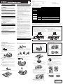
Using Loop-Through Terminals
For this method, cables are connected from terminals 1 and 4 to the
subsequent speaker. Cables with a thickness up to AWG 12 can be used. If
the Euroblock plug is disconnected from a speaker, all subsequent speakers
will not work. This can be useful to identify which speaker has a problem.
Paralleling Input Terminals
For this method, cables are connected to terminals 2 and 3 of each
speaker. Connect two cables to one terminal. Cables with a thickness up
to AWG 17 can be used. Since the cables are connected via Euroblock
plugs, subsequent speakers can work properly.
From amplifier or
previous speakers
To subsequent
speakers
To
subsequent
speakers
Euroblock
plug
Power
amplifier
Speaker
From amplifier or
previous speakers
To subsequent
speakers
Power
amplifier
Speaker
Euroblock
plug
To
subsequent
speakers
Installing the Speakers
Install the speakers onto the ceiling with the supplied hardware. Ensure that
the strength of the ceiling rail is sufficiently strong.
Illustrations in this manual are for the VXC3F. The installation method is the
same for other models.
CAUTION
When attaching the speakers, turn off the power amplifier.
Pre-installation (Preparation of the Cable)
• Use stranded wire for cables attached to the Euroblock plug. Strip their
insulation as shown in the figure and connect them.
Note
Do not plate stranded wires by solder. Doing so will cause the wire to
break.
• Make sure that the release lever of the baffle front is in the position as
shown in the figure below.
1 Put the supplied cutout template to the ceiling and draw a circle by
tracing it.
Make sure to use the cutout template so that hole is the correct
diameter.
Note
If you use a circular cutter, set the diameter with the cutout template.
2 Cut the hole by tracing the circle.
Be careful to prevent chips or powder entering your eyes while
cutting the hole.
1 Insert the two tile rails through the cut hole and place them on the
ceiling surface within your reach. Be sure that each tile rails are
oriented as shown below.
2 Insert the folded O-ring through the cut hole and open it in the ceiling.
3 Secure the O-ring and tile rails with supplied two screws through
either slot of both O-ring brackets.
1
Cut Out a Hole in the Ceiling
2
Install the Tile Rails and O-ring
About 7 mm (0.3 in.)
Maximum thickness of the cable 12 AWG
Release lever
O-ring
Tile rail
1 Pull the wiring from the amplifier through the cut hole of the ceiling.
2 Pass the cable through the terminal cover.
3 After loosening the terminal screws of the Euroblock plug with a flat-
blade screwdriver, insert the cable into each terminal and tighten the
screws. For the connection, refer to “Connecting the Cable”. Make
sure that cables cannot be pulled out.
Note
Use a flat-blade screwdriver with a blade less than 3 mm (0.1 in.).
4 Plug the connected Euroblock plug into the socket in the speaker.
5 Tighten the screw and then attach the terminal cover.
3
Connect the Wiring to the Connector
Euroblock plug
Terminal screw
Loosen
Flat-blade
screwdriver
Tighten
Less than 3 mm (0.1 in.)
1 Take care not to trap the cable, carrying band, or safety wire while
slowly pushing the speaker up into the ceiling.
Make sure the release lever is in the position of the figure below. If it
is set to the position of the figure, when all the Anti-Drop tabs cross
over the O-ring, the speaker is held temporarily.
2 While slightly lifting up the speaker, turn the screwdriver clockwise to
tighten the attachment screw.
The first turn of the attachment screw opens the clamp. Further turns
move the clamp down the channel to pull the speaker up into the
ceiling.
Note
When the clamp is difficult to open, turning the screwdriver halfway
counterclockwise once will make it easier to open the clamp.
CAUTION
• Do not over-tighten the attachment screw. Otherwise, the
attachment screw and clamp will break.
• Do not turn any screws other than attachment screw. Otherwise,
the speaker may fall or malfunction.
4
Fix the Speakers onto the Ceiling
For safety, use the screw hole on the speaker (M5 × 12 mm) and
connect the wire to an independent support point such as a joist.
Example of the connection using an eye bolt
CAUTION
Always take measures to prevent the speaker from falling down.
Use a safety wire of appropriate length. Should the speaker fall and the
wire is too long, the wire may snap due to excess strain.
Safety wire
Eye bolt
Screw hole
(M5 × 12 mm)
Anti-Drop tab
Carrying band
Release lever
Anti-Drop tab
Fixing screw
Clamp
Select the line voltage/impedance (100 V/70 V/8Ω) and power tap for
100 V/70 V line distributed system, by rotating the tap selector switch on
the front side of the speaker with a flat-blade screwdriver.
CAUTION
• The “X” position should not be selected. The 8Ω position should be
selected for 8Ω audio systems only. If the setting is incorrect, it may
cause malfunction of the speaker and amplifier.
• Make sure the amplifier is switched off before operating the tap selector
switch.
Attach the string to the speaker as shown in the figure, then fit the grille to
the magnets (6 places) on the baffle front.
CAUTION
The grille may fall down if it is attached inadequately. Attach it firmly.
Removing from the Ceiling
1 Loosen the fixing screw by turning the screw counterclockwise.
Loosen the screw and the clamp goes up, and as it reaches the top,
the clamp closes as shown in figure below.
2 While slightly lifting up the speaker, secure it by moving the release
lever of the baffle front to the direction of the arrow as shown in the
figure.
3 Remove the safety wire from the speaker that is detached from the
ceiling.
5
Set the Line Voltage/Impedance and Power
6
Attach the Grille
Clamp
Illustration indicates the setting at 15 W for 100 V
line and 7.5 W for 70 V line.
Magnet
Correctly attachedIncorrectly attached
Yamaha Pro Audio global web site:
http://www.yamahaproaudio.com/
Yamaha Manual Library:
http://www.yamaha.co.jp/manual/
Owner’s Manual
SPEAKER SYSTEM
English
ZP40630
EN DE
Auf der Rückseite befindet sich die deutsche Version der Bedienungsanleitung.
-
 1
1

Yamaha VXC5FW Manualul proprietarului
- Tip
- Manualul proprietarului
în alte limbi
- Türkçe: Yamaha VXC5FW El kitabı
- français: Yamaha VXC5FW Le manuel du propriétaire
- čeština: Yamaha VXC5FW Návod k obsluze
- русский: Yamaha VXC5FW Инструкция по применению
- English: Yamaha VXC5FW Owner's manual
- suomi: Yamaha VXC5FW Omistajan opas
- polski: Yamaha VXC5FW Instrukcja obsługi
- Deutsch: Yamaha VXC5FW Bedienungsanleitung
- italiano: Yamaha VXC5FW Manuale del proprietario
- español: Yamaha VXC5FW El manual del propietario
- svenska: Yamaha VXC5FW Bruksanvisning
- dansk: Yamaha VXC5FW Brugervejledning
- português: Yamaha VXC5FW Manual do proprietário
- Nederlands: Yamaha VXC5FW de handleiding
Lucrări conexe
-
Yamaha VXC4W Manualul proprietarului
-
Yamaha VXC6 Manualul proprietarului
-
-
-
-
-
-
Yamaha NS-IC600 Manual de utilizare
-
Yamaha VXS10STW Manualul proprietarului
-