Master B 35-70-100-150-300 Direct Oil Fired Heater Manual de utilizare
- Tip
- Manual de utilizare

USER AND MAINTENANCE MANUAL
B 35CEL B 65CEL B 95CEL B 145CEL
B 35CED B 70CED B 100CED B 150CED B 300CED
B 35CEG B 70CEG B 100CEG B 150CEG
| en | it | de | es | fr | nl | pt | da | fi | no | sv | pl | ru | cs | hu | sl | tr | hr | lt |
| lv | et | ro | sk | bg | uk | bs | el | zh | kk |
Cod. 4100.206 - Ed. 2023 / R. 08


NOTE:_____________________________________________________________________
____________________________________________________________________________
____________________________________________________________________________
____________________________________________________________________________
____________________________________________________________________________
____________________________________________________________________________
____________________________________________________________________________
____________________________________________________________________________
____________________________________________________________________________
____________________________________________________________________________
____________________________________________________________________________
____________________________________________________________________________
____________________________________________________________________________
____________________________________________________________________________
____________________________________________________________________________
____________________________________________________________________________
____________________________________________________________________________
____________________________________________________________________________
____________________________________________________________________________
____________________________________________________________________________
____________________________________________________________________________
____________________________________________________________________________
____________________________________________________________________________
____________________________________________________________________________
____________________________________________________________________________
____________________________________________________________________________
____________________________________________________________________________
____________________________________________________________________________
____________________________________________________________________________
____________________________________________________________________________
____________________________________________________________________________
____________________________________________________________________________
____________________________________________________________________________
____________________________________________________________________________
____________________________________________________________________________
____________________________________________________________________________
____________________________________________________________________________
____________________________________________________________________________
____________________________________________________________________________
____________________________________________________________________________

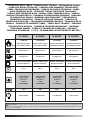
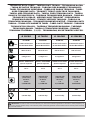
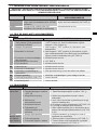
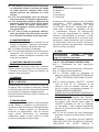
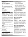
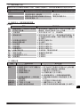
TECHNICAL DATA TABLE - TABELLA DATI TECNICI - TECHNISCHE DATEN
- TABLA DE DATOS TÉCNICOS - TABLEAU DES DONNEES TECHNIQUES -
TABEL TECHNISCHE GEGEVENS - TABELA DE DADOS TÉCNICOS - TABEL
OVER TEKNISKE DATA - TEKNISET TIEDOT SISÄLTÄVÄ TAULUKKO -
TABELL MED TEKNISKE DATA - TABELL ÖVER TEKNISKA DATA - TABELA
DANYCH TECHNICZNYCH - - TABULKA
TABULA - TEHNILISTE ANDMETE TABEL - TABEL DATE TEHNICE -
TECHNICKÝCH ÚDAJOV -
ҚӨ
B 35CEL B 65CEL B 95CEL B 145CEL
MAX
10 kW-кВт
8.600 kcal/h-ккал/ч
34.200 Btu/h-БТЕ/ч
18,5 kW-кВт
15.900 kcal/h-ккал/ч
63.100 Btu/h-БТЕ/ч
29 kW-кВт
25.000 kcal/h-ккал/ч
99.300 Btu/h-БТЕ/ч
44 kW-кВт
37.900 kcal/h-ккал/ч
150.500 Btu/h-БТЕ/ч
280 m³/h-м³/ч 400 m³/h-м³/ч 800 m³/h-м³/ч 900 m³/h-м³/ч
0,8 kg/h-кг/ч 1,5 kg/h-кг/ч 2,3 kg/h-кг/ч 3,5 kg/h-кг/ч
DIESEL-KEROSENE
дизель-керосин
DIESEL-KEROSENE
дизель-керосин
DIESEL-KEROSENE
дизель-керосин
DIESEL-KEROSENE
дизель-керосин
19 l-л 19 l-л 44 l-л 44 l-л
~220-240 V-В
(-15%÷10%)
50 Hz-Гц
0,35 A
0,08 kW-кВт
~220-240 V-В
(-15%÷10%)
50 Hz-Гц
0,8 A
0,18 kW-кВт
~220-240 V-В
(-15%÷10%)
50 Hz-Гц
1 A
0,23 kW-кВт
~220-240 V-В
(-15%÷10%)
50 Hz-Гц
1,2 A
0,28 kW-кВт
RPM 1425 2850 2850 2850
0,20 bar-бар 0,36 bar-бар 0,27 bar-бар 0,34 bar-бар
IMPORTANT: In order to have a correct function you must use an electrical generator in class G3 or more (frequency va-
riation ±1%, tension variation ±2%). The maximum power of electrical generator must be three time the nominal power of device
that you must connected.

B 35CED B 70CED
MAX
10 kW-кВт
8.600 kcal/h-ккал/ч
34.200 Btu/h-БТЕ/ч
20 kW-кВт
17.200 kcal/h-ккал/ч
68.300 Btu/h-БТЕ/ч
280 m³/h-м³/ч 400 m³/h-м³/ч
0,8 kg/h-кг/ч 1,6 kg/h-кг/ч
DIESEL-KEROSENE
дизель-керосин
DIESEL-KEROSENE
дизель-керосин
19 l-л 19 l-л
~220-240 V-В
(-15%÷10%)
50/60 Hz-Гц
0,35 A
0,08 kW-кВт
~220-240 V-В
(-15%÷10%)
50/60 Hz-Гц
0,8 A
0,18 kW-кВт
RPM 1425 2850
0,20 bar-бар 0,36 bar-бар
IMPORTANT: In order to have a correct function you must use an electrical generator in class G3 or more (frequency va-
riation ±1%, tension variation ±2%). The maximum power of electrical generator must be three time the nominal power of device
that you must connected.
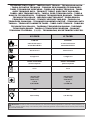
TECHNICAL DATA TABLE - TABELLA DATI TECNICI - TECHNISCHE DATEN
- TABLA DE DATOS TÉCNICOS - TABLEAU DES DONNEES TECHNIQUES -
TABEL TECHNISCHE GEGEVENS - TABELA DE DADOS TÉCNICOS - TABEL
OVER TEKNISKE DATA - TEKNISET TIEDOT SISÄLTÄVÄ TAULUKKO -
TABELL MED TEKNISKE DATA - TABELL ÖVER TEKNISKA DATA - TABELA
DANYCH TECHNICZNYCH - - TABULKA
TABULA - TEHNILISTE ANDMETE TABEL - TABEL DATE TEHNICE -
TECHNICKÝCH ÚDAJOV -
ҚӨ

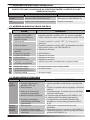
B 100CED B 150CED B 300CED
MAX
29 kW-кВт
25.000 kcal/h-ккал/ч
99.300 Btu/h-БТЕ/ч
44 kW-кВт
37.900 kcal/h-ккал/ч
150.500 Btu/h-БТЕ/ч
88 kW-кВт
75.800 kcal/h-ккал/ч
301.000 Btu/h-БТЕ/ч
800 m³/h-м³/ч 900 m³/h-м³/ч 1.800 m³/h-м³/ч
2,3 kg/h-кг/ч 3,5 kg/h-кг/ч 7 kg/h-кг/ч
DIESEL-KEROSENE
дизель-керосин
DIESEL-KEROSENE
дизель-керосин
DIESEL-KEROSENE
дизель-керосин
44 l-л 44 l-л 105 l-л
~220-240 V-В
(-15%÷10%)
50 Hz-Гц
1 A
0,23 kW-кВт
~220-240 V-В
(-15%÷10%)
50/60 Hz-Гц
1,2 A
0,28 kW-кВт
~220-240 V-В
(-15%÷10%)
50/60 Hz-Гц
2,4 A
0,56 kW-кВт
~220-240 V-В
(-15%÷10%)
60 Hz-Гц
1 A
0,23 kW-кВт
RPM 2850 2850 2850
0,27 bar-бар 0,34 bar-бар 0,40 bar-бар
IMPORTANT: In order to have a correct function you must use an electrical generator in class G3 or more (frequency va-
riation ±1%, tension variation ±2%). The maximum power of electrical generator must be three time the nominal power of device
that you must connected.
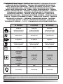
TECHNICAL DATA TABLE - TABELLA DATI TECNICI - TECHNISCHE DATEN
- TABLA DE DATOS TÉCNICOS - TABLEAU DES DONNEES TECHNIQUES -
TABEL TECHNISCHE GEGEVENS - TABELA DE DADOS TÉCNICOS - TABEL
OVER TEKNISKE DATA - TEKNISET TIEDOT SISÄLTÄVÄ TAULUKKO -
TABELL MED TEKNISKE DATA - TABELL ÖVER TEKNISKA DATA - TABELA
DANYCH TECHNICZNYCH - - TABULKA
TABULA - TEHNILISTE ANDMETE TABEL - TABEL DATE TEHNICE -
TECHNICKÝCH ÚDAJOV -
ҚӨ

B 35CEG B 70CEG B 100CEG B 150CEG
MAX
10 kW-кВт
8.600 kcal/h-ккал/ч
34.200 Btu/h-БТЕ/ч
20 kW-кВт
17.200 kcal/h-ккал/ч
68.300 Btu/h-БТЕ/ч
29 kW-кВт
25.000 kcal/h-ккал/ч
99.300 Btu/h-БТЕ/ч
44 kW-кВт
37.900 kcal/h-ккал/ч
150.500 Btu/h-БТЕ/ч
280 m³/h-м³/ч 400 m³/h-м³/ч 800 m³/h-м³/ч 900 m³/h-м³/ч
0,8 kg/h-кг/ч 1,6 kg/h-кг/ч 2,3 kg/h-кг/ч 3,5 kg/h-кг/ч
DIESEL-KEROSENE
дизель-керосин
DIESEL-KEROSENE
дизель-керосин
DIESEL-KEROSENE
дизель-керосин
DIESEL-KEROSENE
дизель-керосин
19 l-л 19 l-л 44 l-л 44 l-л
~220-240 V-В
(-15%÷10%)
50 Hz-Гц
0,35 A
0,08 kW-кВт
~220-240 V-В
(-15%÷10%)
50 Hz-Гц
0,8 A
0,18 kW-кВт
~220-240 V-В
(-15%÷10%)
50 Hz-Гц
1 A
0,23 kW-кВт
~220-240 V-В
(-15%÷10%)
50 Hz-Гц
1,2 A
0,28 kW-кВт
RPM 1425 2850 2850 2850
0,20 bar-бар 0,36 bar-бар 0,27 bar-бар 0,34 bar-бар
IMPORTANT: In order to have a correct function you must use an electrical generator in class G3 or more (frequency va-
riation ±1%, tension variation ±2%). The maximum power of electrical generator must be three time the nominal power of device
that you must connect.
TECHNICAL DATA TABLE - TABELLA DATI TECNICI - TECHNISCHE DATEN
- TABLA DE DATOS TÉCNICOS - TABLEAU DES DONNEES TECHNIQUES -
TABEL TECHNISCHE GEGEVENS - TABELA DE DADOS TÉCNICOS - TABEL
OVER TEKNISKE DATA - TEKNISET TIEDOT SISÄLTÄVÄ TAULUKKO -
TABELL MED TEKNISKE DATA - TABELL ÖVER TEKNISKA DATA - TABELA
DANYCH TECHNICZNYCH - - TABULKA
TABULA - TEHNILISTE ANDMETE TABEL - TABEL DATE TEHNICE -
TECHNICKÝCH ÚDAJOV -
ҚӨ

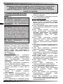
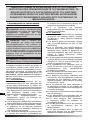
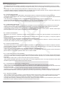
FIGURES - FIGURE - ABBILDUNGEN - FIGURAS - FIGURES - FIGUREN - FI-
GURAS - FIGURER - KUVAT - FIGURER - BILDER - RYSUNKI - OB-
SLIKE - -
ONISED -
-
7
1
2
34
56
8
9 10
1

FIGURES - FIGURE - ABBILDUNGEN - FIGURAS - FIGURES - FIGUREN - FI-
GURAS - FIGURER - KUVAT - FIGURER - BILDER - RYSUNKI - OB-
SLIKE - -
ONISED -
-
7
1
2
34
56
8
9 10
1

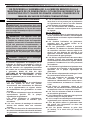
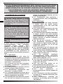
IMPORTANT: READ AND UNDERSTAND THIS OPERATIONAL MANUAL
BEFORE PERFORMING ASSEMBLY, COMMISSIONING OR MAINTENANCE
ON THIS HEATER. INCORRECT USE OF THE HEATER CAN CAUSES
SERIOUS INJURY.
KEEP THIS MANUAL FOR FURTHER REFERENCE.
1. INFORMATION REGARDING
SAFETY
WARNINGS
IMPORTANT: This air heater has
been designed for mobile and temporary
professional applications. It has not been
designed for domestic use nor for thermal
comfort of human.
IMPORTANT: This appliance is not
intended for use by persons (including
children) with reduced physical, senso-
ry and mental capacities or with lack of
experience or knowledge unless super-
vised by a person responsible for their
safety. Children must be supervised to
make sure they neither do nor play with
the appliance.
DANGER: Suocation by carbon
monoxide can be fatal.
The rst symptoms of suocation by
carbon monoxide are similar to those of
u with headache, light-headedness and/or
nausea. These symptoms could be caused
by the faulty functioning of the heater. IF
THESE SYMPTOMS SHOULD OCCUR, DO
OUTDOORS IMMEDIATELY and have the
generator repaired by a technical after-
sales centre.
►►1.1. TOPPING-UP:
►1.1.1. Sta in charge of top-up must be
qualied and understand the manufac-
turer’s instructions and the Standards in
force regarding safe top-up of the heat-
ers.
►1.1.2. Only use the type of fuel express-
ly specied on the heater identication
plate.
►1.1.3. Before topping-up, switch the heat-
er o and wait for it to cool down.
►1.1.4. The fuel storage tanks must be in a
separate structure.
►1.1.5. All fuel tanks must be at a minimum
safety distance from the heater, accord-
ing to the Standards in force.
►1.1.6. The fuel must be kept in rooms
where the oor does not allow penetra-
tion and dripping of the same onto ames
below, which can cause ignition.
►1.1.7. The fuel must be stored in compli-
ance with the Standard in force.
►►1.2. SAFETY:
►1.2.1. Never use the heater in rooms
where petrol, solvents for paints or other
highly inammable vapours are present.
►1.2.2. During use of the heater, follow
all local regulations and the Standard in
force.
►1.2.3. The heaters in proximity of tarpau-
lin, curtains or other similar covering
materials, must be situated at a safe dis-
tance from the same. It is advised to use
re-proof covering material.
►1.2.4. Only use in well-ventilated areas.
Set-up a suitable opening according to
the Laws in force, with the purpose of in-
troducing fresh air from outdoors.
►1.2.5. Power the heater only with current
that has voltage and frequency specied
on the heater identication plate.
►1.2.6. Only use extensions with three
wires, appropriately connected to earth.
►1.2.7. Minimum safety distances recom-
mended, running between the heater and
the inammable substances are: front
output = 2,5 m; side, at top and on rear =
1,5 m.
►1.2.8. Put the heater in hot mode or run-
ning, on a stable level surface, in a way to
prevent the risk of re.
►1.2.9. Keep animals at a safe distance
from the heater.
►1.2.10. Disconnect the heater from the
mains socket when not in use.
►1.2.11. When it is controlled by a
thermostat, the heater can switch on at
any time.
►1.2.12. Never use the heater in frequently
inhabited rooms, or in the bedroom.
►1.2.13. Never block the air vent (rear side)
or the air outlet (front side) of the heater.
en
it
de
es
fr
nl
pt
da
no
sv
pl
ru
cs
hu
sl
tr
hr
lt
lv
et
ro
sk
bg
uk
bs
el
zh

►1.2.14. When the heater is hot or connected
to the mains electricity or functioning, it
must never be moved, handled, topped-
up or subject to any maintenance
interventions.
►1.2.15. Do not duct the air entering or
exiting the heater.
►1.2.16. Keep the hot parts of the heater at
an adequate distance from inammable
or termolabile materials (including the
power supply cable).
►1.2.17. If the power supply cable is
damaged, it must be replaced by the
technical after-sales centre, in order to
prevent all risks.
2.1. Remove all packaging materials used
to wrap and deliver the heater and dispose
of them in compliance with the Standards in
force.
2.2. Extract all articles from the packaging.
2.3. Control for any damage undergone
during transport. If the heater appears
damaged, inform the dealer, where the
purchase was made, immediately.
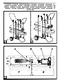
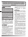
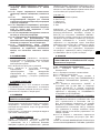
3. ASSEMBLY (29-44 kW)
(SEE FIG. 1)
These models have wheels and handle/s de-
pending on the model. These components,
complete with relative nuts and bolts, are situ-
ated in the heater box.
4. FUEL
WARNING: The heater only functions
with DIESEL or KEROSENE.
Only use diesel or kerosene, to prevent the risk
solvents for paints, alcohol or other highly
Use non-toxic anti-freeze additives in the case
of very low temperatures.
The series of compressor products has a wide
range of power. Models are available with
chambers. For heaters with a double combustion
chamber, the two combustion chambers can
be used simultaneously for maximum power,
or a single combustion chamber can be used
for intermediate power.
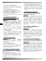
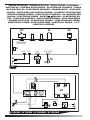
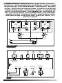
(SEE FIG. 2)
A. Combustion chamber and heads,
B. Fan,
C. Motor,
D. Compressor,
E. Tank.
The compressor (D) started by the motor
(C) compresses the air, which through the
atomising nozzle, sucks up the fuel from the
contact with the igniter, the atomised fuel
ignites inside the combustion chamber (A).
The combustion products are mixed with the
the fan (B) and pushed towards the outside of
the heater. A photoresistance, connected to
a circuit board, constantly checks the correct
functioning of the heater, stopping the cycle in
the event of anomalies.
6. FUNCTIONING
WARNING: Thoroughly read the
”INFORMATION REGADRING SAFETY”,
before switching the heater on.
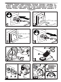
►►6.1. SWITCHING THE HEATER ON:
6.1.1. Follow all instructions relative to safety.
6.1.2. Check the presence of fuel in the tank.
6.1.3. Close the tank cap.
6.1.4. Connect the power supply plug to
6.1.5.
should switch-on within a few seconds. If
the heater does not start, consult the “13.
CHAMBER: To use the heater at maximum
(I). To use the heater at intermediate power
selecting ignition of the single chamber are
on the control panel and on the combustion
chamber.
6.1.6. For the models with room thermostat,
check the position of the knob (SEE FIG.
9-10).
OFF DUE TO THE LACK OF FUEL, TOP-UP
PAR. 6.2).
en
it
de
es
fr
nl
pt
da
no
sv
pl
ru
cs
hu
sl
tr
hr
lt
lv
et
ro
sk
bg
uk
bs
el
zh

►►6.2. RESETTING THE HEATER:
5-4).
►►6.3. SWITCHING THE HEATER OFF:
6.3.1.
(O) position (SEE FIG. 5).
6.3.2. Disconnect the heater from the mains
electricity (SEE FIG. 6).
technical service center)
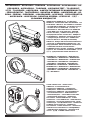
(SEE FIG. 7)
TO BE RESTORED WITH WEAR OF THE
HEATER.
7.1.
identify the correct pressure (Bar - PSI - kPa)
of your heater.
7.2. Remove the screw/cap of the manometer
connection (A).
7.3. Assemble the manometer (not supplied,
7.4. Switch the heater on.
7.5. Act on the regulation screw by turning it
clockwise to increase the pressure and anti-
clockwise to decrease it (B).
7.6. Remove the manometer and restore the
screw/cap (A).
8. CLEANING THE TANK FILTER
(SEE FIG. 8)
8.1. Remove the cap (A) from the tank.
8.2.
8.3.
attention not to damage it.
8.4.
8.5. Close the cap (A).
FOLLOWED.
9.1. Empty the fuel tank (some models have
a draining cap on the bottom of the tank. In
this case, remove the drain cap and empty
the fuel).
9.2. If the presence of residues is noted, pour
9.3. Close the tank cap and/or the draining
cap and dispose of the fuel appropriately
according to the Standards in force.
9.4. In order to keep the heater in the best
way possible, it must be kept on a level
surface to prevent the escape of fuel and in
a dry place away from any possible external
threats.
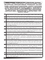
10. ROOM THERMOSTAT
►►10.1. MODELS PRE-SET FOR REMOTE
ROOM THERMOSTAT:
(SEE FIG. 9)
For models preset for remote room thermostat,
remove the cover connected to the heater
(A), connect the thermostat (B) (optional) and
set the desired room temperature. The room
the set temperature has been reached. If the
temperature drops below the set temperature,
the heater will automatically turn itself on again.
►►10.2. MODELS WITH ROOM
THERMOSTAT INSTALLED ON THE
CONTROL PANEL:
(SEE FIG. 10)
For models with room thermostat installed on
the control panel, when the knob (B) is turned
display (A) for a few seconds, after which the
display shows the room temperature. When the
knob (B) is turned completely to the right, the
works continuously.
►►10.3. MODELS PRE-SET FOR REMOTE
ROOM THERMOSTAT AND ROOM
THERMOSTAT INSTALLED ON THE
CONTROL PANEL:
(SEE FIG. 9-10)
For models preset for remote room thermostat
and room thermostat installed on the control
panel, remove the cover connected to the
heater (SEE A FIG. 9) and connect the
thermostat (SEE B FIG. 9) (optional). For
correct heater operation, completely turn the
knob to the right (SEE B FIG. 10), the display
the desired temperature on the remote room
thermostat.
en
it
de
es
fr
nl
pt
da
no
sv
pl
ru
cs
hu
sl
tr
hr
lt
lv
et
ro
sk
bg
uk
bs
el
zh

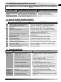
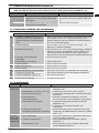
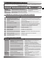
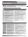
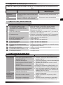
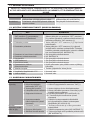
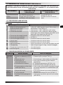
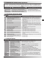
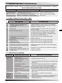
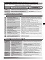
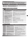
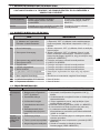
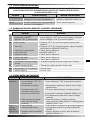
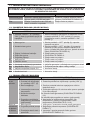
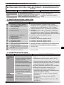
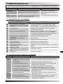
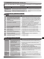
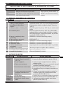
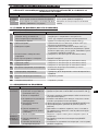
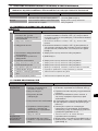
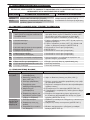
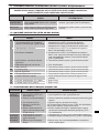
WARNING: BEFORE PERFORMING ANY MAINTENANCE OR REPAIRS, DISCONNECT
THE POWER SUPPLY CABL FROM THE MAINS AND MAKE SURE THAT THE HEATER IS
COLD.
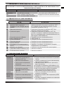
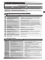
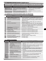
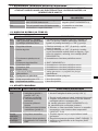
MAINTENANCE FREQUENCY
Fuel tank Empty and rinse the tank with clean
fuel every 150-200 working hours
Empty and rinse the tank with
clean fuel (SEE PAR. 9)
Filters Clean or replace every 500 working
hours or when necessary
Contact the technical service
center
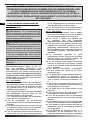
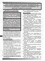
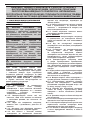
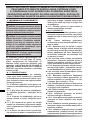
(SEE FIG. 10)
CAUSE SOLUTION
F0 1.
plugged in
1. After disconnecting the heater, see that the
F1
2. Fuel is contaminated
3. Photocell is dirty or damaged
5. Ignition error
3. Contact the technical service center
4. SEE PAR. 8
5. Contact the technical service center
F2 1. Interrupted cable
2. Sensor is damaged
1. Contact the technical service center
2. Contact the technical service center
F3 1. Internal heater overheating
F4 1. Incorrect voltage 1. Check voltage of your electric supply system
LO 1. External temperature below -5°C
CH 1. Continuous operation
13. TROUBLESHOOTING
The heater
does not
start
1. Generator blocked
2.
position (0)
3.
4. Temperature sensor override
5. Control card blocked
6. Incorrect setting of the room
thermostat (where present)
1. Reset the heater (SEE PAR. 6.2)
2.
position
3. Insert the power supply cable into the
mains socket correctly
4. Wait at least ten minutes then try to run
ignition again
5a. Reset the heater (SEE PAR. 6.2)
5b. Identify the display error (where present)
6. Act on the room thermostat, taking it to a
higher temperature than that of the work
environment (SEE FIG. 9-10)
The motor
starts but
not triggered
1.
2. Incorrect pump pressure
3. Presence of foreign
substances in the tank
1. Top-up fuel and reset the heater
2. Regulate the pressure of the compressor
(SEE PAR. 7)
3.
PAR. 9)
en
it
de
es
fr
nl
pt
da
no
sv
pl
ru
cs
hu
sl
tr
hr
lt
lv
et
ro
sk
bg
uk
bs
el
zh

IMPORTANTE: LEGGERE E COMPRENDERE QUESTO MANUALE
OPERATIVO PRIMA DI EFFETTUARE L’ASSEMBLAGGIO, LA MESSA
IN FUNZIONE O LA MANUTENZIONE DI QUESTO RISCALDATORE.
L’USO ERRATO DEL RISCALDATORE PUÒ CAUSARE LESIONI GRAVI.
CONSERVARE QUESTO MANUALE A TITOLO DI FUTURO RIFERIMENTO.
1. INFORMAZIONI SULLA SICUREZZA
AVVERTENZE
IMPORTANTE: Questo riscaldatore
d’aria è stato progettato per applicazioni
professionali mobili e temporanee. Non è
destinato all’uso domestico, né al comfort
termico delle persone.
IMPORTANTE: Questo apparecchio non
è adatto all’uso da parte di persone (incluse
bambini) con capacità siche, sensoriali e
mentali ridotte, o inesperte, a meno che non
vengano supervisionate da una persona re-
ponsabile per la loro sicurezza. I bambini
devono essere controllati, per assicurarsi
che non giochino con l’apparecchio.
PERICOLO: L’asssia da ossido di
carbonio può risultare fatale.
I primi sintomi di asssia da ossido di car-
bonio assomigliano a quelli dell’inuenza,
con cefalee, capogiri e/o nausea. Tali sintomi
potrebbero essere causati dal funzionamento
difettoso del riscaldatore. NEL CASO SI PRE-
SENTASSERO QUESTI SINTOMI, USCIRE IM-
MEDIATAMENTE ALL’APERTO e far riparare il
riscaldatore dal centro assistenza tecnica.
►►1.1. RIFORNIMENTO:
►1.1.1. Il personale incaricato del rifornimen-
to, deve essere qualicato ed avere totale
dimestichezza con le istruzioni del fabbri-
cante e con la normativa vigente in merito al
rifornimento sicuro dei riscaldatori.
►1.1.2. Usare solamente il tipo di combustibi-
le espressamente specicato sulla targhetta
identicativa del riscaldatore.
►1.1.3. Prima di eettuare il rifornimento,
spegnere il riscaldatore, ed attendere che si
rareddi.
►1.1.4. Le cisterne di magazzinaggio del car-
burante devono trovarsi in una struttura se-
parata.
►1.1.5. Tutti i serbatoi del combustibile, de-
vono trovarsi ad una distanza minima di
sicurezza dal riscaldatore, secondo norme
vigenti.
►1.1.6. Il combustibile va conservato in lo-
cali il cui pavimento non permetta la pe-
netrazione ed il gocciolio dello stesso su
amme sottostanti, che possano causarne
l’accensione.
►1.1.7. La conservazione del combustibile va
eettuata in conformità alla normativa vi-
gente.
►►1.2. SICUREZZA:
►1.2.1. Non usare mai il riscaldatore in locali
nei quali siano presenti benzina, solventi per
vernici o altri vapori altamente inammabili.
►1.2.2. Durante l’uso del riscaldatore, attener-
si a tutte le ordinanze locali ed alla norma-
tiva vigente.
►1.2.3. I riscaldatori usati in prossimità di te-
loni, tende o altri materiali simili di coper-
tura, devono essere situati a distanza di si-
curezza da essi. Si consiglia anche di usare
materiali di copertura di tipo ignifugo.
►1.2.4. Usare solamente in aree ben ventilate.
Predisporre un’apertura adeguata secondo
le norme vigenti, allo scopo di immettere
aria fresca dall’esterno.
►1.2.5. Alimentare il riscaldatore solamente
con corrente avente tensione e frequenza
specicate sulla targhetta identicativa del
riscaldatore.
►1.2.6. Usare solamente prolunghe a tre li
opportunamente collegate a massa.
►1.2.7. Distanze minime di sicurezza, con-
sigliate, intercorrente tra il riscaldatore e le
sostanze inammabili sono: uscita anterio-
re = 2,5 m; di lato, in alto e sul retro = 1,5 m.
►1.2.8. Porre il riscaldatore caldo, o in fun-
zione, su una supercie stabile e livellata, in
modo da evitare i rischi di incendio.
►1.2.9. Tenere gli animali a distanza di si-
curezza dal riscaldatore.
►1.2.10. Scollegare il riscaldatore dalla presa
di rete, quando non lo si usa.
►1.2.11. Quando è controllato da un termo-
stato, il riscaldatore può accendersi in qual-
siasi momento.
►1.2.12. Non usare mai il riscaldatore in stan-
ze frequentemente abitate né, in camere da
letto.
►1.2.13. Non bloccare mai la presa dell’aria
(lato posteriore), né l’uscita dell’aria (lato
anteriore) del riscaldatore.
►1.2.14. Quando il riscaldatore è caldo, o col-
legato alla rete elettrica, o in funzione non
en
it
de
es
fr
nl
pt
da
no
sv
pl
ru
cs
hu
sl
tr
hr
lt
lv
et
ro
sk
bg
uk
bs
el
zh

deve mai essere spostato, maneggiato, ri-
fornito né soggetto ad alcun intervento di
manutenzione.
►1.2.15. Non canalizzare l’aria né in entrata e
nè in uscita del riscaldatore.
►1.2.16. Mantenere una adeguata distanza da
materiali inammabili, o termolabili (comp-
reso il cavo di alimentezione) dalle parti cal-
de del riscaldatore.
►1.2.17. Se il cavo di alimentazione risulta
danneggiato, deve essere sostituito dal cen-
tro assistenza tecnica, in modo da prevenire
ogni rischio.
2. DISIMBALLAGGIO
2.1. Rimuovere tutti i materiali di imballaggio
usati per confezionare e spedire il riscaldatore
e smaltirli secondo le norme vigenti.
2.2. Estrarre tutti gli articoli dall’imballo.
2.3. Controllare eventuali danni subiti durante il
trasporto. Se il riscaldatore appare danneggia-
to, informare immediatamente il concessionario
presso il quale è stato acquistato.
3. ASSEMBLAGGIO (29-44 kW)
(VEDI FIG. 1)
maniglia a seconda del modello. Tali componenti,
completi della relativa bulloneria di montaggio,
sono situati nella scatola del riscaldatore.
4. COMBUSTIBILE
AVVERTENZA: Il riscaldatore funziona solo
con DIESEL o KEROSENE.
Usare solamente diesel o kerosene, per evitare ri-
di benzina, nafta, solventi per vernici, alcool o altri
Usare additivi antigelo non tossici in caso di tem-
perature molto basse.
La serie di prodotti a compressore ha un ampia
gamma di potenzialità e sono disponibili modelli
a singola camera di combustione e modelli a
i riscaldatori a doppia camera di combustione
si possono usare contemporaneamente le due
camere di combustione per la massima potenza,
oppure una singola camera di combustione per la
potenza intermedia.
(VEDI FIG. 2)
A. Camera e testa combustione,
B. Ventola,
C. Motore,
D. Compressore,
E. Serbatoio.
Il compressore (D) messo in funzione dal motore
(C) comprime l’aria, che attraverso l’ugello
nebulizzatore, aspira il combustibile dal serbatoio
nebulizzato, a contatto con l’accenditore, si
incendia all’interno della camera di combustione
(A). I prodotti della combustione vengono
dalla rotazione della ventola (B) e spinti verso
l’esterno del riscaldatore. Una fotoresistenza,
collegata ad una scheda elettronica di controllo,
del riscaldatore, arrestando il ciclo in caso di
anomalie.
6. FUNZIONAMENTO
AVVERTENZA: Leggere attentamente le
”INFORMAZIONI SULLA SICUREZZA”,
prima di accendere il riscaldatore.
►►6.1. ACCENSIONE DEL RISCALDATORE:
6.1.1. Seguire tutte le istruzioni relative alla
sicurezza.
6.1.2. Controllare la presenza di combustibile
nel serbatoio.
6.1.3. Chiudere il tappo del serbatoio.
6.1.4. Collegare la spina di alimentazione
“
6.1.5. Portare l’interruttore “
posizione “
dovrebbe accendersi entro pochi secondi. Se il
riscaldatore non si avvia, consultare il paragrafo
“13.
Per utilizzare il riscaldatore
alla massima potenza portare entrambi gli
mentre per utilizzare la potenza intermedia
camera di combustione si trovano i riferimenti
per gestire e selezionare l’accensione della
singola camera.
6.1.6. Per i modelli con termostato ambiente,
FIG. 9-10).
DEL COMBUSTIBILE, RABBOCCARE IL
SERBATOIO E RESETTARE IL RISCALDATORE
(VEDI PARAG. 6.2).
en
it
de
es
fr
nl
pt
da
no
sv
pl
ru
cs
hu
sl
tr
hr
lt
lv
et
ro
sk
bg
uk
bs
el
zh

►►6.2. RESET DEL RISCALDATORE:
riaccendere il generatore (VEDI FIG. 5-4).
►►6.3. SPEGNIMENTO DEL
RISCALDATORE:
6.3.1. Portare l’interruttore “
posizione “.
6.3.2. Scollegare il riscaldatore dalla rete
elettrica (VEDI FIG. 6).
centro di assistenza)
(VEDI FIG. 7)
COMPRESSORE.
“
la corretta pressione (Bar - PSI - kPa) del vostro
riscaldatore.
7.2. Rimuovere la vite/tappo dell’attacco
manometro (A).
7.3. Montare il manometro (non in dotazione,
vedi “
7.4. Accendere il riscaldatore.
7.5. Agire sulla vite di regolazione ruotando in
senso orario per aumentare la pressione e in
senso antiorario per diminuirla (B).
7.6. Rimuovere il manometro e ripristinare la
vite/tappo (A).
(VEDI FIG. 8)
FILTRO SERBATOIO.
8.1. Rimuovere il tappo (A) del serbatoio.
facendo attenzione a non danneggiarlo.
8.5. Chiudere il tappo (A).
9.1. Svuotare il serbatoio dal combustibile (alcuni
modelli sono dotati di un tappo di scarico posto
sul fondo del serbatoio. In tal caso, rimuovere il
tappo di scarico e svuotare il combustibile).
9.2. Se si nota la presenza di residui, versare
combustibile pulito nel serbatoio e scaricare
nuovamente.
9.3. Chiudere il tappo del serbatoio e/o
eventualmente il tappo di scarico e smaltire il
combustibile in modo appropriato e secondo le
norme vigenti.
si consiglia di mantenerlo in posizione livellata,
per evitare la fuoriuscita del combustibile e di
conservalo in un luogo asciutto, e al riparo da
possibili danni esterni.
10. TERMOSTATO AMBIENTE
►►10.1. MODELLI CON PREDISPOSIZIONE
TERMOSTATO AMBIENTE REMOTO:
(VEDI FIG. 9)
Per i modelli con predisposizione termostato
ambiente remoto, rimuovere il tappo collegato
al riscaldatore (A), connettere il termostato (B)
(optional) e impostare la temperatura ambiente
desiderata. Il termostato ambiente remoto disattiva
completamente il riscaldatore una volta raggiunta
la temperatura impostata. Se la temperatura
scende sotto la temperatura impostata, il
riscaldatore si riattiva automaticamente.
►►10.2. MODELLI CON TERMOSTATO
AMBIENTE INSTALLATO SUL PANNELLO
COMANDI:
(VEDI FIG. 10)
Per i modelli con termostato ambiente installato
sul pannello comandi, ruotando la manopola (B),
la temperatura desiderata inizierà a lampeggiare
sul display (A) per alcuni secondi, in seguito il
display visualizzera la temperatura ambiente.
Ruotando completamente la manopola (B) verso
destra, sul display (A) compare “CH“ a quel punto
il riscaldatore funzionera in continuo.
►►10.3. MODELLI CON PREDISPOSIZIONE
TERMOSTATO AMBIENTE REMOTO E
TERMOSTATO AMBIENTE INSTALLATO SUL
PANNELLO COMANDI:
(VEDI FIG. 9-10)
Per i modelli con predisposizione termostato
ambiente remoto e termostato ambiente installato
sul pannello comandi, rimuovere il tappo collegato
al riscaldatore (VEDI A FIG. 9) e connettere il
termostato (VEDI B FIG. 9) (optional). Per un
corretto funzionamento del riscaldatore, ruotare
completamente la manopola verso destra (VEDI
B FIG. 10), sul display (VEDI A FIG. 10) compare
“CH“ e impostare la temperatura desiderata sul
termostato ambiente remoto.
en
it
de
es
fr
nl
pt
da
no
sv
pl
ru
cs
hu
sl
tr
hr
lt
lv
et
ro
sk
bg
uk
bs
el
zh

AVVERTENZA: PRIMA SI EFFETTUARE QUALSIASI MANUTENZIONE O RIPARAZIONE,
SCOLLEGARE IL CAVO DI ALIMENTAZIONE DALLA RETE ELETTRICA, ED ASSICURARSI CHE IL
RISCALDATORE SIA FREDDO.
FREQUENZA MANUTENZIONE
Serbatoio del
combustibile
Pulire ogni 150-200 ore di lavoro o a
seconda delle necessità
Svuotare e risciacquare il serbatoio con
combustibile pulito (VEDI PARAG. 9)
Filtri Pulire o sostituire ogni 500 ore di
lavoro o a seconda delle necessità
Rivolgersi al centro di assistenza tecnica
(VEDI A FIG. 10)
CAUSA SOLUZIONE
F0 1. L’interuttore “
posizione “
riscaldatore viene collegato alla rete
elettrica
1. Dopo aver scollegato il riscaldatore dalla rete
elettrica posizionare l’interrutore in posizione “
(0), ricollegare la spina alla rete elettrica e portare
l’interuttore in posizione “
F1 1. Mancanza carburante
2. Carburante sporco
3.
4. Filtro carburante sporco
5. Errore accensione
1. Posizionare l’interrutore in posizione “
riempire il serbatoio di carburante
2. Posizionare l’interrutore in posizione “
svuotare e riempire il serbatoio di carburante. Pulire il
danneggiarlo (VEDI PARAG. 8)
3. Rivolgersi al centro di assistenza tecnica
4. VEDI PARAG. 8
5. Rivolgersi al centro di assistenza tecnica
F2 1. Terminale interrotto
2. Sensore difettoso
1. Rivolgersi al centro di assistenza tecnica
2. Rivolgersi al centro di assistenza tecnica
F3 1. Riscaldatore in sovratemperatura
interna
1. Spegnere il riscaldatore, ed attendere il completo
F4 1. Tensione non adeguata 1.
LO 1. Temperatura esterna inferiore a -5°C 1.
CH 1. Funzionamento in continuo 1.
Il riscaldatore
non parte
1. Riscaldatore in blocco
2. Interruttore di acensione in
posizione “
3. Mancanza alimentazione
4. Limite sensore temperatura
intervenuto
5. Scheda di controllo in blocco
6. Impostazione errata del
termostato ambiente (dove
presente)
1. Resettare il riscaldatore (VEDI PARAG. 6.2)
2. Portare l’interruttore di accensione in posizione
“
3. Inserire correttamente il cavo di alimentazione
alla presa di rete elettrica
4. Attendere almeno dieci minuti e riprovare la
fase di accensione
5a. Resettare il riscaldatore (VEDI PARAG. 6.2)
(dove presente)
6. Agire sul termostato ambiente, portandolo
ad una temperatura superiore a quella
dell’ambiente di lavoro (VEDI FIG. 9-10)
Il motore
parte ma la
innesca
1. Mancanza combustibile
2. Pressione errata della pompa
3. Presenza di sostanza estranee
nel serbatoio
1. Rifornire combustibile ed eventualmente
resettare il riscaldatore
2. Regolare la pressione del compressore (VEDI
PARAG. 7)
3. Svuotare e riempire il serbatoio con carburante
pulito (VEDI PARAG. 9)
en
it
de
es
fr
nl
pt
da
no
sv
pl
ru
cs
hu
sl
tr
hr
lt
lv
et
ro
sk
bg
uk
bs
el
zh

WICHTIGER HINWEIS: DIESE BEDIENUNGSANLEITUNG MUSS VOR
ZUSAMMENBAU, INBETRIEBNAHME BZW. WARTUNG DES HEIZGERÄTES
GELESEN UND VERSTANDEN WORDEN SEIN. FALSCHER GEBRAUCH
DES HEIZGERÄTES KANN ZU SCHWEREN VERLETZUNGEN FÜHREN.
BEWAHREN SIE DIESE ANLEITUNG ZUM SPÄTEREN NACHSCHLAGEN
GUT AUF.
1. SICHERHEITSHINWEISE
WARNHINWEISE
WICHTIGER: Dieses Luftheizgerät wurde
für mobile und temporäre professionelle
Anwendungen entwickelt. Es wurde weder
für den häuslichen Gebrauch noch für
den thermischen Komfort des Menschen
entwickelt.
WICHTIGER HINWEIS: Dieses Gerät ist
nicht geeignet für den Gebrauch durch Per-
sonen (einschließlich Kindern) mit begrenz-
ten körperlichen, sensorischen und geistigen
Fähigkeiten bzw. ohne ausreichende Fach-
kenntnis, es sei denn, sie werden durch eine
für ihre Sicherheit verantwortliche Person
beaufsichtigt. Kinder sind zu beaufsichtigen,
damit sie nicht mit dem Gerät spielen.
VORSICHT: Kohlenmonoxid kann zum
Tod durch Ersticken führen.
Die ersten Anzeichen einer
Kohlenmonoxidvergiftung sind denen von
Grippe mit Kopfschmerzen, Schwindel bzw.
Übelkeit ähnlich. Diese Symptome können
auf eine Betriebsstörung des Heizgeräts
zurückzuführen sein. SOLLTEN DIESE
SYMPTOME AUFTRETEN, SOFORT INS
FREIE GEHEN und das Heizgerät durch den
Kundendienst reparieren lassen.
►►1.1. NACHFÜLLEN DES BRENNSTOFFS:
►1.1.1. Das mit dem Nachfüllen des Brennstos
beauftragte Personal muss gut ausgebildet
und mit den Anweisungen des Herstellers
und den geltenden Vorschriften zum sicheren
Nachfüllen von Brennsto in Heizgeräte
vertraut sein.
►1.1.2. Verwenden Sie nur die ausdrücklich
auf dem Typenschild des Heizgerätes
angegebene Brennstoart.
►1.1.3. Vor dem Nachfüllen ist das Heizgerät
abzuschalten und muss abgekühlt sein.
►1.1.4. Die Brennstoagerbehälter müssen
sich in einem getrennten Gebäude benden.
►1.1.5. Alle Brennstotanks müssen sich
gemäß geltenden Vorschriften in einem
sicheren Abstand vom Heizgerät benden.
►1.1.6. Der Brennsto ist in Räumen zu lagern,
deren Fußböden so abgedichtet sind, dass
ein Eindringen und Tropfen des Brennstos
auf oene Flammen darunter nicht möglich
ist, denn dadurch könnte es zum Entzünden
des Brennstos kommen.
►1.1.7. Die Lagerung des Brennstos muss
gemäß geltenden Vorschriften erfolgen.
►►1.2. SICHERHEIT:
►1.2.1. Heizgerät niemals in Räumen benutzen,
in denen sich Benzin, Lösungsmittel für
Farben oder andere hoch entzündliche
Dämpfe benden.
►1.2.2. Während des Betriebs des Heizgeräts
sind alle örtlichen Bestimmungen und
geltenden Vorschriften zu beachten.
►1.2.3. Beim Betrieb des Heizgerätes ist ein
Sicherheitsabstand von Planen, Vorhängen
oder ähnlichen Materialien einzuhalten. Es
wird auch empfohlen, Abdeckungen aus
nicht brennbarem Material zu verwenden.
►1.2.4. Nur in gut belüfteten Bereichen
verwenden. Es ist eine nach den geltenden
Vorschriften ausreichende Önung zur
Zuführung von Frischluft von außen
vorzusehen.
►1.2.5. Die Stromversorgung des Heizgeräts
muss die auf dem Typenschild des
Heizgerätes angegebene Spannung und
Frequenz aufweisen.
►1.2.6. Nur dreiadrige, ordnungsgemäß
geerdete Verlängerungskabel benutzen.
►1.2.7. Empfohlene Mindest-
Sicherheitsabstände zwischen Heizgerät
und brennbaren Stoen: Vorderseite = 2,5 m;
seitlich, oben und hinten = 1,5 m.
►1.2.8. Das Heizgerät muss, wenn es heiß
oder in Betrieb ist, auf einer stabilen und
ebenen Fläche stehen, um Brandgefahren zu
vermeiden.
►1.2.9. Halten Sie Haustiere in einem sicheren
Abstand vom Heizgerät.
►1.2.10. Trennen Sie das Heizgerät vom
Stromnetz, wenn Sie es nicht benutzen.
►1.2.11. Wenn das Heizgerät über einen
Thermostaten gesteuert wird, kann es sich
jederzeit einschalten.
►1.2.12. Benutzen Sie das Heizgerät niemals in
stark frequentierten Wohnräumen, und auch
nicht in Schlafzimmern.
en
it
de
es
fr
nl
pt
da
no
sv
pl
ru
cs
hu
sl
tr
hr
lt
lv
et
ro
sk
bg
uk
bs
el
zh

►1.2.13. Niemals die Luftzufuhr (Rückseite)
oder die Luftaustrittsönung (Vorderseite)
des Heizgeräts blockieren.
►1.2.14. Wenn das Heizgerät heiß oder an das
Stromnetz angeschlossen oder in Betrieb ist,
darf es niemals bewegt oder nachgefüllt oder
gewartet werden.
►1.2.15. Weder Luftzufuhr noch Luftaustritt
des Heizgeräts dürfen über Kanäle geleitet
werden.
►1.2.16. Zwischen brennbaren bzw.
wärmeempndlichen Stoen (einschließlich
des Netzkabels) und den heißen Teilen
des Geräts ist ein ausreichender Abstand
einzuhalten.
►1.2.17. Wenn das Netzkabel beschädigt
ist, muss es durch den Kundendienst
ausgetauscht werden, um Gefahren
auszuschließen.
2.1. Entfernen Sie alle für Verpackung und
Versand des Heizgeräts verwendeten Materialien
und entsorgen Sie diese vorschriftsgemäß.
2.2.
2.3. Kontrollieren Sie, ob Transportschäden
vorliegen. Wenn das Gerät beschädigt ist, sofort
den Vertragshändler informieren, bei dem es
erworben wurde.
3. ZUSAMMENBAU (29-44 kW)
(SIEHE ABB. 1)
Diese Modelle besitzen je nach Modell Räder und
Schrauben zur Montage im Karton des Heizgeräts.
4. BRENNSTOFF
WARNHINWEIS: Das Heizgerät arbeitet nur
mit DIESEL oder KEROSIN.
Nur winter diesel unter 5C.
Verwenden Sie nur Diesel oder Kerosin, um Brand-
oder Explosionsgefahren zu vermeiden. Benutzen
Verwenden Sie bei sehr niedrigen Temperaturen
ungiftige Frostschutzzusätze.
5. FUNKTIONSGRUNDSÄTZE
Die Baureihen der Verdichterprodukte verfügen über
eine große Bandbreite an Leistungen. Die Modelle
sind sowohl mit einzelner als auch mit doppelter
angrenzender Verbrennungskammer erhältlich. Bei
Heizgeräten mit doppelter Verbrennungskammer
gleichzeitig für maximale Leistung oder nur eine
einzige Verbrennungskammer für eine mittlere
Leistungsstufe verwendet werden.
(SIEHE ABB. 2)
A. Brennkammer und -kopf,
B. Gebläse,
C. Motor,
D. Kompressor,
E. Tank.
Der Kompressor (D) wird durch Motor (C)
angetrieben und verdichtet die Luft, die über die
in der Brennkammer (A). Die Verbrennungsprodukte
werden mit dem Raumluftstrom vermischt, der
durch den Betrieb des Gebläses (B) erzeugt
wird, und aus dem Heizgerät ausgestoßen. Über
der Steuerelektronik verbunden ist, wird ständig
der Betrieb des Heizgerätes überwacht und bei
6. BEDIENUNG
WARNHINWEIS: Vor dem Ein schal ten/
Zünden des Heizgerätes sind die “SICHER-
HEITSHINWEISE” aufmerksam durchzulesen.
►►6.1. INBETRIEBNAHME DES
HEIZGERÄTES:
6.1.1. Beachten Sie sämtliche Sicherheitshinweise.
6.1.2.
6.1.3. Schließen Sie den Tankdeckel.
6.1.4.
6.1.5.
(SIEHE ABB. 4). Das Heizgerät sollte sich
innerhalb weniger Sekunden einschalten. Sollte
das Heizgerät nicht starten, schauen Sie in
Abschnitt „13. FEHLERSUCHE“ nach.
MODELLE MIT DOPPELTER
Um das Heizgerät
mit maximaler Leistung zu verwenden, beide
Heizgerät auf einer mittleren Leistungsstufe zu
und auf der Verbrennungskammer sind Hinweise
einzelnen Kammer angebracht.
6.1.6. Bei Modellen mit Raumthermostat die
Stellung des Reglerknopfes kontrollieren (SIEHE
ABB. 9-10).
en
it
de
es
fr
nl
pt
da
no
sv
pl
ru
cs
hu
sl
tr
hr
lt
lv
et
ro
sk
bg
uk
bs
el
zh

►►6.2. RESET DES HEIZGERÄTES:
Bei Modellen mit automatischem „RESET“ das
Heizgerät aus- und wieder einschalten (SIEHE
ABB. 5-4).
►►6.3. ABSCHALTEN DES HEIZGERÄTES:
6.3.1.
(SIEHE ABB. 5).
6.3.2. Heizgerät vom Stromnetz nehmen (SIEHE
ABB. 6).
7. REGELUNG DES DRUCKS DES
anrufen)
(SIEHE ABB. 7)
7.1.
Ihres Heizgerätes.
7.2. Entfernen Sie Schraube/Verschluss des
Manometeranschlusses (A).
7.3. Manometer anbauen (nicht mitgeliefert,
7.4. Heizgerät einschalten.
7.5.
nach rechts drehen und nach links, um ihn zu
verringern (B).
7.6. Manometer entfernen und Schraube/
Verschluss (A) wieder anbringen.
8. REINIGEN DES
BRENNSTOFFFILTERS
(SIEHE ABB. 8)
8.1. Tankdeckel (A) entfernen.
8.2. Filter (B) aus dem Tank nehmen.
8.3.
reinigen.
8.4. Filter (B) wieder in den Tank einsetzen.
8.5. Tankdeckel (A) schließen.
9. LAGERUNG UND
9.1.
Modelle haben einen Entleerungsverschluss
am Boden des Tanks. In diesem Fall den
Entleerungsverschluss entfernen und den
9.2. Sollten Reste zurückbleiben, sauberen
9.3. Tankdeckel und gegebenenfalls
in geeigneter Weise und vorschriftsgemäß
entsorgen.
9.4. Das Heizgerät sollte am besten in gerader
Stellung gelagert werden, um das Austreten
trockenen Ort, geschützt vor äußerlichen
Beschädigungen.
10. RAUMTHERMOSTAT
►►10.1. MODELLE, DIE FÜR EINEN
EXTERNEN RAUMTHERMOSTAT
VOREINGESTELLT SIND:
(SIEHE ABB. 9)
Für Modelle, die für einen externen Raumthermostat
voreingestellt sind, die mit dem Heizgerät (A)
verbundene Abdeckung entfernen, den Thermostat
(B) anschließen (optional) und die gewünschte
Raumtemperatur einstellen. Der Raumthermostat
sorgt für eine komplette Abschaltung des Heizgeräts
sobald die eingestellte Temperatur erreicht wird.
Wenn die Temperatur unter den eingestellten
Temperaturwert sinkt, wird das Heizgerät
automatisch wieder in Betrieb genommen.
►►10.2. MODELLE MIT AUF DER
BEDIENTAFEL INSTALLIERTEM
RAUMTHERMOSTAT:
(SIEHE ABB. 10)
Bei den Modellen, die über einen auf der
Bedientafel installierten Raumthermostat verfügen,
blinkt nach Drehen des Knopfs (B) die gewünschte
Temperatur einige Sekunden lang auf dem Display
(A), anschließend wird auf dem Display die
Raumtemperatur angezeigt. Wird der Knopf (B)
ganz nach rechts gedreht, wird am Display (A) „CH“
angezeigt, anschließend arbeitet das Heizgerät
kontinuierlich.
►►10.3. MODELLE, DIE FÜR EINEN
EXTERNEN RAUMTHERMOSTAT UND EINEN
AUF DER BEDIENTAFEL INSTALLIERTEN
RAUMTHERMOSTAT VOREINGESTELLT SIND:
(SIEHE ABB. 9-10)
Für Modelle, die für einen externen Raumthermostat
und einen auf der Bedientafel installierten
Raumthermostat voreingestellt sind, die mit dem
Heizgerät (A) verbundene Abdeckung entfernen
(SIEHE A ABB. 9) und den Thermostat (SIEHE
B ABB. 9) anschließen (optional). Für den
einwandfreien Betrieb des Heizgeräts den Knopf
ganz nach rechts drehen (SIEHE B ABB. 10), am
Display (SIEHE A ABB. 10) wird „CH“ angezeigt,
anschließend kann die gewünschte Temperatur am
externen Raumthermostat eingestellt werden.
en
it
de
es
fr
nl
pt
da
no
sv
pl
ru
cs
hu
sl
tr
hr
lt
lv
et
ro
sk
bg
uk
bs
el
zh
Pagina se încarcă...
Pagina se încarcă...
Pagina se încarcă...
Pagina se încarcă...
Pagina se încarcă...
Pagina se încarcă...
Pagina se încarcă...
Pagina se încarcă...
Pagina se încarcă...
Pagina se încarcă...
Pagina se încarcă...
Pagina se încarcă...
Pagina se încarcă...
Pagina se încarcă...
Pagina se încarcă...
Pagina se încarcă...
Pagina se încarcă...
Pagina se încarcă...
Pagina se încarcă...
Pagina se încarcă...
Pagina se încarcă...
Pagina se încarcă...
Pagina se încarcă...
Pagina se încarcă...
Pagina se încarcă...
Pagina se încarcă...
Pagina se încarcă...
Pagina se încarcă...
Pagina se încarcă...
Pagina se încarcă...
Pagina se încarcă...
Pagina se încarcă...
Pagina se încarcă...
Pagina se încarcă...
Pagina se încarcă...
Pagina se încarcă...
Pagina se încarcă...
Pagina se încarcă...
Pagina se încarcă...
Pagina se încarcă...
Pagina se încarcă...
Pagina se încarcă...
Pagina se încarcă...
Pagina se încarcă...
Pagina se încarcă...
Pagina se încarcă...
Pagina se încarcă...
Pagina se încarcă...
Pagina se încarcă...
Pagina se încarcă...
Pagina se încarcă...
Pagina se încarcă...
Pagina se încarcă...
Pagina se încarcă...
Pagina se încarcă...
Pagina se încarcă...
Pagina se încarcă...
Pagina se încarcă...
Pagina se încarcă...
Pagina se încarcă...
Pagina se încarcă...
Pagina se încarcă...
Pagina se încarcă...
Pagina se încarcă...
Pagina se încarcă...
Pagina se încarcă...
Pagina se încarcă...
Pagina se încarcă...
Pagina se încarcă...
Pagina se încarcă...
Pagina se încarcă...
Pagina se încarcă...
Pagina se încarcă...
Pagina se încarcă...
Pagina se încarcă...
Pagina se încarcă...
Pagina se încarcă...
Pagina se încarcă...
Pagina se încarcă...
Pagina se încarcă...
Pagina se încarcă...
Pagina se încarcă...
Pagina se încarcă...
Pagina se încarcă...
Pagina se încarcă...
Pagina se încarcă...
Pagina se încarcă...
Pagina se încarcă...
Pagina se încarcă...
Pagina se încarcă...
Pagina se încarcă...
Pagina se încarcă...
Pagina se încarcă...
Pagina se încarcă...
Pagina se încarcă...
Pagina se încarcă...
Pagina se încarcă...
Pagina se încarcă...
Pagina se încarcă...
Pagina se încarcă...
Pagina se încarcă...
Pagina se încarcă...
Pagina se încarcă...
Pagina se încarcă...
Pagina se încarcă...
Pagina se încarcă...
Pagina se încarcă...
Pagina se încarcă...
Pagina se încarcă...
Pagina se încarcă...
Pagina se încarcă...
Pagina se încarcă...
Pagina se încarcă...
Pagina se încarcă...
Pagina se încarcă...
Pagina se încarcă...
Pagina se încarcă...
Pagina se încarcă...
Pagina se încarcă...
Pagina se încarcă...
-
 1
1
-
 2
2
-
 3
3
-
 4
4
-
 5
5
-
 6
6
-
 7
7
-
 8
8
-
 9
9
-
 10
10
-
 11
11
-
 12
12
-
 13
13
-
 14
14
-
 15
15
-
 16
16
-
 17
17
-
 18
18
-
 19
19
-
 20
20
-
 21
21
-
 22
22
-
 23
23
-
 24
24
-
 25
25
-
 26
26
-
 27
27
-
 28
28
-
 29
29
-
 30
30
-
 31
31
-
 32
32
-
 33
33
-
 34
34
-
 35
35
-
 36
36
-
 37
37
-
 38
38
-
 39
39
-
 40
40
-
 41
41
-
 42
42
-
 43
43
-
 44
44
-
 45
45
-
 46
46
-
 47
47
-
 48
48
-
 49
49
-
 50
50
-
 51
51
-
 52
52
-
 53
53
-
 54
54
-
 55
55
-
 56
56
-
 57
57
-
 58
58
-
 59
59
-
 60
60
-
 61
61
-
 62
62
-
 63
63
-
 64
64
-
 65
65
-
 66
66
-
 67
67
-
 68
68
-
 69
69
-
 70
70
-
 71
71
-
 72
72
-
 73
73
-
 74
74
-
 75
75
-
 76
76
-
 77
77
-
 78
78
-
 79
79
-
 80
80
-
 81
81
-
 82
82
-
 83
83
-
 84
84
-
 85
85
-
 86
86
-
 87
87
-
 88
88
-
 89
89
-
 90
90
-
 91
91
-
 92
92
-
 93
93
-
 94
94
-
 95
95
-
 96
96
-
 97
97
-
 98
98
-
 99
99
-
 100
100
-
 101
101
-
 102
102
-
 103
103
-
 104
104
-
 105
105
-
 106
106
-
 107
107
-
 108
108
-
 109
109
-
 110
110
-
 111
111
-
 112
112
-
 113
113
-
 114
114
-
 115
115
-
 116
116
-
 117
117
-
 118
118
-
 119
119
-
 120
120
-
 121
121
-
 122
122
-
 123
123
-
 124
124
-
 125
125
-
 126
126
-
 127
127
-
 128
128
-
 129
129
-
 130
130
-
 131
131
-
 132
132
-
 133
133
-
 134
134
-
 135
135
-
 136
136
-
 137
137
-
 138
138
-
 139
139
-
 140
140


Master B 35-70-100-150-300 Direct Oil Fired Heater Manual de utilizare
- Tip
- Manual de utilizare
în alte limbi
Lucrări înrudite
-
MCS Master B 70CEG Manualul proprietarului
-
Master CEL CED CEG 2014 Manualul proprietarului
-
-
-
-
-
-
Master BV 471S Manual de utilizare
-
-