Yamaha DME Manual de utilizare
- Categorie
- Instrumente muzicale
- Tip
- Manual de utilizare
Acest manual este potrivit și pentru

DME Setup Manual 1
DME Setup Manual
This manual describes the process of setting up a DME system, from making the initial DME processor settings
(DME64N / DME24N / DME8i-C / DME8o-C / DME4io-C / DME8i-ES / DME8o-ES / DME4io-ES) to synchronizing with
the DME Designer application installed on a computer.
n For details about the DME units refer to the manual supplied with the specific device, and for details about the DME Designer
application refer to the pdf-format DME Designer manual.
n In this document the term “DME” will refer to the DME64N, DME24N, DME8i-C, DME8o-C, DME4io-C, DME8i-ES, DME8o-ES and
DME4io-ES, while the term “DME Satellite” will refer only to the DME8i-C, DME8o-C, DME4io-C, DME8i-ES, DME8o-ES and DME4io-ES.
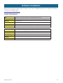
Workflow
Software Installation
● DME Designer and DME-N Network Driver installation (page 3).
● USB-MIDI Driver installation (page 4).
DME Network Setup (page 6)
Connecting via a USB cable and setting the DME IP address and Device Group Master/Slave status from the
DME Designer.
Computer to DME Connection (page 8)
The procedures for connecting a single DME unit to a computer as well as for connecting multiple DME units to a
computer in the same subnet are described. Refer to the DME manual for information on audio connection and
further network connection details.
Computer Network Setup
These settings must be made properly when connecting a computer to DME units via an Ethernet cable.
● Computer TCP/IP settings (page 9).
● DME-N Network Driver settings (page 11).
DME Designer Operation
● Creating Configurations (page 12).
Explains the process of launching the DME Designer application and combining and connecting various
audio components to create configurations.
● Going Online (page 14)
Explains how to go online and transfer configurations created using the DME Designer application to DME
devices.
Troubleshooting (page 17)
Appendix
● DME64N/24N Network Setup via Panel Operation (page 19).
● DME-N Network Driver Setup Details (page 20).

DME Setup Manual 2
Begin by downloading the DME Designer Combo Installer and the USB-MIDI Driver from the “Downloads” page on
the Yamaha Pro Audio website.
http://www.yamahaproaudio.com/
System Requirements
Software Installation
OS
Windows
®
XP Professional/XP Home Edition/2000 Professional
CPU
1 GHz or higher Intel
®
Core
™
/Pentium
®
/Celeron
®
family processor
Memory
256 MB or more
Hard disk space
300 MB or more
Display
1,280 x 1,024 pixels or higher; High Color 16-bit or higher
Other
Mouse, 100Base-TX/10Base-T Ethernet or USB connection
OS
Windows
®
Vista Ultimate/Business/Enterprise
CPU
1.4 GHz or higher Intel
®
Core
™
/Pentium
®
/Celeron
®
family processor
Memory
1 GB or more
Hard disk space
300 MB or more
Display
1,280 x 1,024 pixels or higher; High Color 16-bit or higher
Other
Mouse, 100Base-TX/10Base-T Ethernet or USB connection

DME Setup Manual 3
●●●●●●●●●●●●●●●●●●●●●●●●●●●●●●●●●●●●●●●●●●●●●●●●●●●●●●●●●●●●●●●●●●●●●●●●●●●●●●●
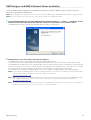
DME Designer and DME-N Network Driver Installation
Install the DME Designer application and DME-N Network Driver from the DME Designer Combo Installer by
following the procedure outlined below.
n The following procedure is applicable even if an older version of the DME Designer and/or DME-N Network Driver is already installed.
n Be sure to read the license agreement at the end of this document before installing this software.
1 Open the downloaded and extracted “DME Designer Combo Installer V*.*.*” folder (*.*.* will be the version
number on the actual file), and double-click the “setup.exe” file located in the “Installer” folder.
The DME Designer Combo Installer setup dialog window will appear on the display.
2 Follow the on-screen instructions to install the software.
The DME Designer will be installed first, followed by the DME-N Network Driver.
If a previous version of the DME Designer and/or DME Network Driver exists on the computer, the older software will be
uninstalled before installation of the new software begins. After the older software has been uninstalled, you will be asked to
restart the computer. In this case the computer must be restarted before the installation process can continue. The installer
will automatically be re-launched and the installation will continue after the computer has been restarted.
The software will be installed in a “DME Designer” folder in the “Program Files\YAMAHA\OPT Tools” folder (default).
n Refer to the pdf-format DME Designer manual for operating instructions. The manual is not installed by the installer. Download the
manual separately from the “Downloads” page on the Yamaha Pro Audio website.
http://www.yamahaproaudio.com/
n DME Designer V3 cannot communicate with DME devices using firmware version 2 or earlier. If you are using DME Designer V3, be
sure to update the DME device firmware to the latest version that can be downloaded from Yamaha Pro Audio website.
http://www.yamahaproaudio.com/
n The installer will launch automatically when the computer is restarted after the uninstall process, but in rare cases the installer may
be hidden by the task bar. In such cases click this icon to continue the installation.

DME Setup Manual 4
●●●●●●●●●●●●●●●●●●●●●●●●●●●●●●●●●●●●●●●●●●●●●●●●●●●●●●●●●●●●●●●●●●●●●●●●●●●●●●●
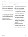
USB-MIDI Driver Installation
n You can also refer to the installation guide supplied with the driver for detailed installation procedures.
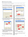
■ Windows Vista
1 Start the computer and log on with
administrator privileges while power to the DME
is off.
2 Connect the computer to the DME unit via a USB
cable.
3 Turn the DME power on: “Found New Hardware”
will be displayed.
4 Select [Locate and install driver software
(recommended)] ➞ [Don’t search online].
5 When a message appears prompting you to
insert the supplied disc, select [I don’t have the
disc. Show me other options.] ➞ [Browse my
computer for driver software (advanced).] ➞
[Browse], specify the downloaded and extracted
“Driver” folder, then click [OK].
6 Click [Next] to start installation.
7 When a message appears indicating that the
driver has been successfully installed, click
[Finish].
The driver has been installed.
■ Windows XP
1 Start the computer and log on with
administrator privileges while power to the DME
is off.
2 Select [Start] ➞ [Control Panel], and then
“Switch to Classic View” in the upper left of the
display to show all control panels and icons.
3 Select [System] ➞ [Hardware] ➞ [Driver Signing]
➞ [File Signature Verification], and check the
radio button to the left of “Ignore—Install all
files, regardless of file signature” and click [OK].
Restore this setting to its original state after the
installation has been completed.
4 While the DME power is still off, connect the
computer to the DME unit via a USB cable.
5 Turn the DME power on, and the “Found New
Hardware Wizard” message will appear
automatically.
6 Select [Install from a list or specific location
(Advanced).] ➞ [Search for the best driver in
these locations], check only [Include this
location in the search], click [Browse] to specify
the downloaded and extracted “Driver” folder,
then click [OK].
7 Click [Next] to start the installation.
8 When a message appears indicating that the
driver has been successfully installed, click
[Finish].
9 Restart the computer when a message appears
prompting you to do so.
The driver has been installed.

DME Setup Manual 5
■ Windows 2000
1 Start the computer and log on with
administrator privileges while power to the DME
is off.
2 Select [My Computer] ➞ [Control Panel] ➞
[System] ➞ [Hardware] ➞ [Driver Signing] ➞
[File Signature Verification] and check the radio
button to the left of “Ignore—Install all files,
regardless of file signature” and click [OK].
Restore this setting to its original state after the
installation has been completed.
3 While the DME power is still off, connect the
computer to the DME unit via a USB cable.
4 Turn the DME power on, and the “Found New
Hardware Wizard” message will appear
automatically.
Click [Next].
5 Select [Search for a suitable driver for my device
(recommended)] ➞ [Specify a location], click
[Browse] to specify the downloaed and
extracted “Driver” folder, then click [OK].
6 Click [Next] to start the installation.
7 When a message appears indicating that the
driver has been successfully installed, click
[Finish].
8 Restart the computer when a message appears
prompting you to do so.
The driver has been installed.

DME Setup Manual 6
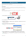
After connecting the computer to the DME unit via a USB cable, the Device Group and IP address for each DME
unit can be individually set from the DME Designer.
n These parameters can also be set directly via the panel controls and displays of the DME64N and DME24N (page 19).
Device Group
When a system uses multiple DME units, the DME units can be controlled from the DME Designer application in
Device Groups. Since all devices in a group are controlled via the Device Group Master, one device in each group
must be assigned as the master device.
IP Address
All devices to be included in the same group must be assigned the same network address. The Device Group
Master is specified by its host address.
1 While the DME power is off, connect the computer to the DME unit via a USB cable.
2 Turn the DME power on.
3 Click [Start] ➞ [All Programs] ➞ [YAMAHA OPT Tools] ➞ [DME Designer] ➞ [DME Designer] to launch the
DME Designer application.
4 Click the MIDI Setup button to open the MIDI dialog box.
n If you can’t locate the MIDI Setup button on the display, it is most probably hiding in the taskbar. Double-click it to open the MIDI
dialog box.
5 Select the “YAMAHA USB IN 0-1” or “Yamaha DME NETWORK-1” input port in the [In] field, and the
“YAMAHA USB OUT 0-1” or “Yamaha DME NETWORK-1” output port in the [Out] field, and click [OK].
n If the DME port does not appear in the MIDI dialog box, check that the DME device’s power is turned on, and re-launch the DME
Designer application.
DME Network Setup
Network address Host address
USB cable

DME Setup Manual 7
6
From the DME Designer main panel, click [Port] in the [Setup] menu to open the Port dialog box.
7 Select “YAMAHA USB OUT 0-1” or “Yamaha DME NETWORK-1” in the [Tx] field, and “YAMAHA USB IN 0-
1” or “Yamaha DME NETWORK-1” in the [Rx] field, and click [OK].
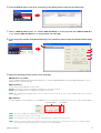
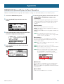
8 In the main panel window click [Network Setup] in the [Hardware] menu to open the Network Setup dialog
box.
9 Make the following network settings, then click [OK].
1 MIDI Port List (Tx/Rx)
Select “YAMAHA USB OUT 0-1/YAMAHA USB IN 0-1” or “Yamaha DME NETWORK-1/Yamaha DME NETWORK-1” as the
DME port for the network settings.
2 Master/Slave
Selects Device Group Master or Slave status.
Master: One device must be assigned as the Master in each Device Group.
Slave: All other DME devices in the group should be set to Slave.
n When DME64N/24N and DME Satellite units are combined in a Device Group, be sure to assign a DME Satellite unit as the Group
Master.
3 IP Address
Set the IP addresses of the DME devices. All DME devices in the same Device Group must be set to the same network address.
n When only one DME device (Master) is used, set the IP address to “192.168.0.2”.
n The subnet mask is fixed at “255.255.255.0”.
n The host address can be set from 2 to 253 for the Master device, and from 3 to 253 for Slaves.
n Always use a private address (192.168.0.2. through 192.168.255.253) unless it is absolutely necessary to use a global address.
Consult with the network administrator if it is necessary to use a global address.
1
2
3
4
5
Network address
Host address

DME Setup Manual 8
4 Master ID
When a device is assigned as a Slave in Master/Slave (2) above, this sets the host address for the Master device in that
group. This parameter cannot be set for the Master device.
5 Link Mode
Make sure that “100Base-TX” is selected.
10 If the system includes multiple DME devices, repeat the above settings for each individual device.
Refer to the DME manual for information on audio connection and further network connection details.
n If you will be using CobraNet™ for audio connections, the required bundle numbers and related settings must be made via the DME
Designer application.
n If you will be using EtherSound™ for audio connections, the routing and other EtherSound settings must be made via the AuviTran AVS-
ESMonitor software available from the AuviTran website:
http://www.auvitran.com/view.php?products_AVS-ESMonitor.php
Directly Connecting a Single DME Device to a Computer
When only one DME device is to be controlled, connect the device to the computer via a USB cable as described
in “DME Network Setup” on page 6.
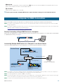
Connecting Multiple DME Devices to a Computer in the Same Subnet
Connect multiple DME devices to the computer via a switching hub and Ethernet cables.
n It is possible to connect the computer to the Device Group Master using a USB cable.It is also possible to connect the computer to a
Slave DME using a USB cable if a DME Satellite is assigned as the Device Group Master.
n Use a switching hub that is capable of 100Base-TX operation.
n The maximum length of cables that can be used to connect DME units to a switching hub is 100 meters. Proper operation at this length,
however, will depend on the quality of the hub and cables used, and cannot be guaranteed.
n Use CAT5 STP (shielded twisted pair) type cable to maximize resistance to electromagnetic interference.
Computer to DME Connection
USB cable
Group Master
DME Satellite (IP Address: 192.168.0.2)
Device Group
Ethernet cable
Ethernet cable
Ethernet straight cable
Ethernet straight cable
DME Satellite
(IP Address: 192.168.0.3)
(Master ID: 2)
DME64N/24N
(IP Address: 192.168.0.250)
(Master ID: 2)
Computer
(IP Address: 192.168.0.100)
Switching hub

DME Setup Manual 9
These settings must be made when DME devices are connected via Ethernet cables.
●●●●●●●●●●●●●●●●●●●●●●●●●●●●●●●●●●●●●●●●●●●●●●●●●●●●●●●●●●●●●●●●●●●●●●●●●●●●●●●
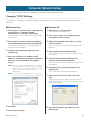
Computer TCP/IP Settings
The computer’s IP address and TCP/IP filtering must be set up to allow network communication with the DME
device(s).
■ Windows Vista
1 Select [Start] ➞ [Control Panel] ➞ [Network and
Sharing Center] ➞ [Manage network
connections] ➞ [Local Area Connection].
The “Local Area Connection Properties” dialog box will
be displayed.
2 Select [Internet Protocol Version 4 (TCP/Ipv4)]
on the [Networking] tab, then click [Properties].
The “Internet Protocol Version 4 (TCP/IPv4) Properties”
dialog box will be displayed.
3 Click [Use the following IP address] on the
[General] tab.
4 Enter your computer’s IP address into [IP
address], the Gateway’s IP address into [Default
gateway], and “255.255.255.0” into [Subnet
mask].
n When the computer and DME devices are connected in
the same subnet as described on page 8, the network
address must be set to that same address as the DME
devices, while the host address must be set to a
different value.
n
When the computer and DME devices are connected in
the same subnet, Set the gateway IP host address to 254.
5 Click [OK].
6 Restart your computer
■ Windows XP
1 Select [Start] ➞ [Control Panel].
The “Control Panel” is displayed.
2 If the “Control Panel” is in Category display,
click [Switch to Classic View].
3 Double-click [Network Connections] ➞ [Local
Area Connection].
The “Local Area Connection Status” dialog box will be
displayed.
4 Click [Properties] on the [General] tab.
The “Local Area Connection Properties” dialog box will
be displayed.
5 Select [Internet Protocol (TCP/IP)] on the
[General] tab, then click [Properties].
The “Internet Protocol (TCP/IP) Properties” dialog box will
be displayed.
6 Click [Advanced...], then [Properties] on the
[Options] tab.
The “TCP/IP Filtering” dialog will be displayed.
7 Select “Permit All” for TCP Ports, then click
[OK].
The display returns to the “Advanced TCP/IP Settings”
dialog. Click [OK] to return to the “Internet Protocol (TCP/
IP) Properties” dialog.
8 Click [Use the following IP address] on the
[General] tab.
Computer Network Setup

DME Setup Manual 10
9 Enter your computer’s IP address into [IP
address], the Gateway’s IP address into [Default
gateway], and “255.255.255.0” into [Subnet
mask].
n When the computer and DME devices are connected in
the same subnet as described on page 8, the network
address must be set to that same address as the DME
devices, while the host address must be set to a
different value.
n
When the computer and DME devices are connected in
the same subnet, Set the gateway IP host address to 254.
10 Click [OK].
11 Restart your computer.
■ Windows 2000
1 Select [Start] ➞ [Settings] ➞ [Control Panel] ➞
[Network and Dial-Up Connections] ➞ [Local
Area Connection].
The “Local Area Connection Status” dialog box will be
displayed.
2 Steps 4 and after are the same as for Windows
XP.

DME Setup Manual 11
●●●●●●●●●●●●●●●●●●●●●●●●●●●●●●●●●●●●●●●●●●●●●●●●●●●●●●●●●●●●●●●●●●●●●●●●●●●●●●●
DME-N Network Driver Settings
In order for the computer to recognize the DME device(s), it is necessary to register the IP address and device
name of the DME device that is the Device Group Master.
1
Connect the DME device(s) to the computer as
described on
page 8
, and turn the DME power on.
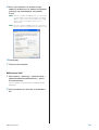
2 Double-click [Start] ➞ [Control Panel] ➞ [DME-N
Network Driver] to open the DME-N Network
Driver dialog box.
3 Click the [Advanced Settings] button to open the
“Advanced Settings” dialog box.
DME devices connected to the network can be
automatically detected via this dialog box.
4 Enter the IP address range over which you
would like to automatically detect connected
DME devices in the [Detect from] and [Detect to]
fields, and click [Start].
Automatic DME device detection will begin.
5 When automatic DME device detection has
finished, check the [Add] box of the DME device
that is to function as the Device Group Master,
and click [Add to Device List].
The “Advanced Settings” dialog box will close and return
to the “DME-N Network Driver” dialog box.
n If the IP address was not automatically detected,
register the DME device manually (page 20).
6 Select the DME unit that is to function as the
Device Group Master from the Target Device
List, enter the Device Name and Device Port No.,
and click the [Apply] button.
Device Name
Displayed as the port name in DME Designer.
Device Port No. (MIDI port number)
Set to “1.” “2” is also available for DME64N/24N devices.
7 Click the [Save and Close] button to close the
dialog box.

DME Setup Manual 12
●●●●●●●●●●●●●●●●●●●●●●●●●●●●●●●●●●●●●●●●●●●●●●●●●●●●●●●●●●●●●●●●●●●●●●●●●●●●●●●
Creating Configurations
The process of launching the DME Designer application and combining and connecting various audio components
to create configurations is described below. The DME device(s) can be disconnected from the computer while
creating configurations.
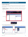
1 Click [Start] ➞ [All Programs] ➞ [YAMAHA OPT Tools] ➞ [DME Designer] ➞ [DME Designer] to launch the
DME Designer application.
When the DME Designer is launched a new project will be created and a new zone (Zone 1) will appear in the designer
window.
If the designer window shown above does not appear, click the main panel window [Show/Hide] button to reveal it.
2 Place the appropriate DME objects in the designer window.
Select the required DME objects from the Toolkit window on the left of the display. Objects can be dragged and dropped into
the zone window, or double-clicked to place them in the current zone.
n Where required set the device group or sampling rate via the dialog box that appears when placing DME objects.
n If the sampling rate set here and the actual sampling rate set for the DME operation are different, excessive DSP may be required
and operation may not be possible. Be sure to match the sampling rates.
DME Designer Operation
Main Panel Window
Designer Window
Drag and Drop, or
Double-click

DME Setup Manual 13
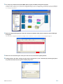
3 As necessary double-click placed DME object to open the DME configuration window.
Individual audio components can be placed and wired together as necessary to create “configurations” in the configuration
window. For this example you can leave the configuration empty. Refer to the DME Designer manual for detailed information
on creating configurations.
4 Select the [Scene Manager] item from the main panel window [Tools] menu to open the Scene Manager
dialog box.
The specified configuration parameter settings can be saved as a “scene” via the Scene Manager dialog box.
5 Select the row containing the scene you want to save, and click the [Store] button.
6 Configurations and other settings can be saved as project files (“.daf” extension) by selecting the [Save
As] command from the main panel window [File] menu.

DME Setup Manual 14
●●●●●●●●●●●●●●●●●●●●●●●●●●●●●●●●●●●●●●●●●●●●●●●●●●●●●●●●●●●●●●●●●●●●●●●●●●●●●●●
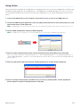
Going Online
After connecting the computer to the DME devices and going online, you can transfer configurations created using
the DME Designer application to the DME devices. The DME devices and DME Designer are “online” when they
are connected and able to communicate with each other. DME devices can also be controlled in real-time when
online.
1 Connect the DME devices to the computer as described on page 8, and turn the DME power on.
2 Launch the DME Designer application, select the [Open] command from the main panel [File] menu, and
open the previously saved project file.
n The DME Designer can also be launched and the project file automatically loaded by simply double-clicking the project file icon.
3 Click the MIDI Setup button to open the MIDI dialog box.
n If the DME ports are not displayed, check that the DME power is on and re-launch the DME Designer application.
4 Select the input and output ports to be used to control the Device Group Master, then click [OK].
When connected via USB select “YAMAHA USB IN 0-1” or “Yamaha DME NETWORK-1”, and “YAMAHA USB OUT 0-1” or
“Yamaha DME NETWORK-1”, and when connected via Ethernet select the device name specified via the DME-N Network
Driver (page 11).
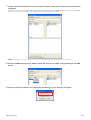
5 Select the [Port] item from the main panel window [Setup] menu to open the Port dialog box.
6 Select the output and input ports specified in step 4 in the [Tx] and [Rx] fields, and the appropriate
Device Group in the [Device Group] field, then click [OK].

DME Setup Manual 15
7 Click the [Synchronization] item in the main panel window [Tools] menu to open the Synchronization
dialog box.
DME objects placed in the DME Designer application will be displayed in the [DME Designer] list on the left, and DME
devices connected to the network will be displayed in the [Network] list on the right.
n If multiple Device Groups have been set up, select the Device Group to be synchronized from the [Group] list.
8 Click the [DME Designer] list [IP Address] field, and select the IP address corresponding to the DME
device.
9 Click the [Go On-line] button, and a dialog box confirming the sync direction will appear.

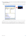
DME Setup Manual 16
10 Select the [DME Designer -> Device] button, then click [OK] and the DME Designer configuration will be
transferred to the DME device.
When synchronization has finished the [Go On-line] button will be grayed out and the main panel window [On-line] button
will light.
n When a configuration has already been transferred to a DME unit, we recommend using the [DME Designer <- Device] button for
synchronization. The transfer time is faster than using the [DME Designer -> Device] button. However, if the configuration has
been edited it is necessary to use the [DME Designer -> Device] button.
To go offline either click the main panel window [On-line] button or the [Go Off-line] button in the Synchronization dialog
box.
For more in-depth information on using the DME Designer application for system design, refer to the pdf-format
DME Designer manual. If you will be using CobraNet for audio connections, the required bundle numbers and
related settings must be made via the DME Designer application. If you will be using EtherSound for audio
connections, the routing and other EtherSound settings must be made via the AuviTran AVS-ESMonitor software.

DME Setup Manual 17
The USB-MIDI Driver cannot be installed.
• Is the USB cable connected correctly?
• Is the USB function enabled on your computer?
When you connect the DME to the computer for the first
time, if the “Add New Hardware Wizard” does not appear,
the USB function on the computer may be disabled.
Perform the following steps.
1 Select [Start] → [Control Panel] (→ [System] →
[Hardware]) → [Device Manager].
The “Device Manager” window appears.
2 Make sure that no “!” or “x” marks appear at “Universal
serial bus controller” or “USB Root Hub.”
If you see the “!” or “x” mark, the USB controller is
disabled. Refer to the owner’s manual of your computer
for details.
• Is any unknown device registered?
If driver installation fails, the DME will be shown as an
“Unknown device,” and you will not be able to install the
driver. Delete the “Unknown device” by following the steps
below.
1 Select [Start] → [Control Panel] (→ [System] →
[Hardware]) → [Device Manager].
The “Device Manager” window appears.
2 Look for “Other devices.”
3 If you find “Other devices,” double-click it to extend the
tree to look for “Unknown device.” If one appears,
select it and click the [Remove] button.
4 Remove the USB cable from the DME, and make the
connection again.
5 Install the driver again according to the instructions
described on page 4.
When controlling the DME from your
computer via USB, the DME does not
operate correctly.
• Did you install the USB-MIDI driver?
• Is the USB cable connected correctly?
•Have you selected an appropriate port in the DME
Designer?
Make sure that the settings in the DME Designer have the
combination of “YAMAHA USB IN 0-1” (Yamaha DME
NETWORK-1) and “YAMAHA USB OUT 0-1” (Yamaha DME
NETWORK-1). The combination of “YAMAHA USB IN 0-2”
and “YAMAHA USB OUT 0-2” can also be used for the
DME64N/24N. Settings combining different port numbers
(i.e., “YAMAHA USB IN 0-1” and “YAMAHA USB OUT 0-2,”
or “YAMAHA USB IN 0-2” and “YAMAHA USB OUT 0-1”)
cannot be used.
• Is the USB-MIDI Driver Thru ON/OFF parameter set
to “OFF”?
Go to [Start] → [Control Panel] → [Yamaha USB-MIDI
Driver] and make sure that the [Thru ON/OFF] parameter is
set to “OFF”.
•Have you selected the same USB ports in both the
DME Designer and another MIDI application?
Change the port setting so that the DME Designer and the
other MIDI applications use different ports.
• Does the number of registered MIDI devices exceed
the Windows limit?
The Windows operating system allows a maximum of 10
MIDI device drivers to be installed and registered. In some
cases changing the USB port to which a device is
connected can cause it to be recognized as a different
device, thereby “artificially” exceeding the limit. If MIDI
doesn't function properly try uninstalling and then re-
installing the USB-MIDI Driver.
• Are you using the latest USB-MIDI Driver supporting
DME?
The latest driver supporting DME can be downloaded from
the Yamaha website.
http://www
.yamahaproaudio.com/
• Did you launch DME Designer after connecting a
USB cable and turning the device ON?
Be sure to connect the USB cable and turn the device on
before launching DME Designer.
•Was the USB cable disconnected during operation?
If the USB cable is accidentally disconnected, DME
designer will not recognize the device even if the cable is
reconnected. You will have to restart DME Designer.
Troubleshooting

DME Setup Manual 18
When controlling the DME from your
computer via Ethernet, the DME does not
operate correctly.
• Is the Ethernet cable connected correctly?
• Is the DME-N Network Driver set up appropriately?
Did you enter an appropriate IP address?
• Is the computer network setup appropriate?
Select [Start] → [Control Panel] → [Network Connections]
→ [Local Area Connection], and confirm the network
setup.
• Are the settings of DME and peripheral network
devices (including switching hubs) appropriate?
Refer to the relevant owner’s manuals for the DME and
peripheral network devices (including switching hubs) for
details.
•Have you selected an appropriate network port in the
DME Designer?
• Are you using the latest DME-N Network Driver
supporting DME?
The latest driver supporting DME can be downloaded from
the Yamaha website.
http://www
.yamahaproaudio.com/
• Do you have security software running on your
system?
Try to disable the security software once. Set it to allow use
of TCP port 12300 on the network card being used by the
DME-N Network Driver.
Cannot suspend or resume the computer
correctly.
• Do not suspend the computer while the DME
Designer is running.
If you are using Windows 2000, you may not be able to
suspend/resume normally, depending on the particular
environment (USB Host Controller, etc.). (Even so, simply
disconnecting and connecting the USB cable will allow
you to use the DME functions again.)
To install one of either the DME Designer
software or DME-N Network Driver:
The software or driver can be individually installed by
double-clicking the “Setup.exe” file located in the
downloaded and extracted “Installer\DMEDesigner_”
or “Installer\Networkdrv_” folder.
To uninstall the DME Designer software:
The DME Designer software can be uninstalled either
via [Start] → [Control Panel] → [Add or Remove
Programs], or via [Start] → [Program Files] →
[YAMAHA OPT Tools] → [DME Designer] → [Uninstall].
To uninstall the DME-N Network Driver:
The DME-N Network Driver can be uninstalled via
[Start] → [Control Panel] → [Add or Remove
Programs].
To uninstall the USB-MIDI Driver:
The USB-MIDI Driver can be uninstalled by double-
clicking the “uninstall.exe” file located in the
downloaded and decompressed “Uninstall” folder.

DME Setup Manual 19
●●●●●●●●●●●●●●●●●●●●●●●●●●●●●●●●●●●●●●●●●●●●●●●●●●●●●●●●●●●●●●●●●●●●●●●●●●●●●●●
DME64N/24N Network Setup via Panel Operation
DME64N and DME24N device group and IP address settings can be made directly via the device’s panel.
1 Turn on the DME64N/24N power.
2 Press the [HOME] key to display the main
screen.
3 Press and hold the [UTILITY] key for more than 2
seconds to display the Utility screen.
4 Press the [UTILITY] a few times until the Net
page appears.
5 Use the [▲] and [▼] keys to move the cursor to
the parameters listed below and press the
[ENTER] key.
The corresponding editing dialog will appear. Make the
settings indicated for each parameter below, and press
the [ENTER] key each time to confirm and enter the
settings.
1 Master/Slave
Selects Device Group Master or Slave status.
Master: One device must be assigned as the Master in
each Device Group.
Slave: All other DME devices in the group should be set
to Slave.
n When DME64N/24N and DME Satellite units are
combined in a Device Group, be sure to assign a DME
Satellite unit as the group Master.
2 IP Address
Set the IP addresses of the DME devices. All DME
devices in the same Device Group must be set to the
same network address.
n When only one DME device (Master) is used, set the IP
address to “192.168.0.2”.
n The subnet mask is fixed at “255.255.255.0”.
n The host address can be set from 2 to 253 for the Master
device, and from 3 to 253 for Slaves.
n Always use a private address (192.168.0.2. through
192.168.255.253) unless it is absolutely necessary to
use a global address. Consult with the network
administrator if it is necessary t use a global address.
3 Master ID
When a device is assigned as a Slave in Master/Slave
(1) above, this sets the host address for the Master
device in that group. This parameter cannot be set for the
Master device.
4 Link Mode
Make sure that “100Base-TX” is selected.
Appendix
1
2
3
4
Network address Host address

DME Setup Manual 20
●●●●●●●●●●●●●●●●●●●●●●●●●●●●●●●●●●●●●●●●●●●●●●●●●●●●●●●●●●●●●●●●●●●●●●●●●●●●●●●
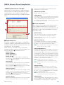
DME-N Network Driver Setup Details
“DME-N Network Driver” Window
Select [Start] → [Control Panel] → [DME-N Network
Driver] to open the “DME-N Network Driver” window.
The parameters in this window set up the device
information to communicate with the DME-N Network
Driver.
1 Target Device List
The name, IP address, MAC address, and MIDI port
number of all devices registered to communicate with
the DME-N Network Driver are shown in this list. Click
the title bars to sort accordingly.
When a device is selected in the list, information
related to that device will be viewed and edited in the
Device information (2) area below the list.
Device Name
Device IP Address
Device MAC Address
Device Port No.
The name, IP address, MAC address, and MIDI port
number of the corresponding device. Refer to the Device
information (2) area for details.
[New] Button
Click this button to add a new device to the list. Edit the
device’s parameters as required via the fields in the
Device information (2) area below the list, the click the
[APPLY] button to add the specified device.
[Duplicate] Button
This button adds a device to the list by copying the data
from the currently selected device. Edit the new device’s
parameters as required via the fields in the Device
information (2) area below the list, then click the [APPLY]
button to add the specified device.
[Remove] Button
Deletes the selected device from the list. If the removed
device is not the lowest device in the list, all devices
below the removed device will be shifted upward to
maintain the continuity of the list.
[Remove ALL] Button
Deletes all devices from the list.
[Undo] Button
This button provides a one-step undo function that allows
you to undo a single operation and revert to the previous
state. The [Undo] button will be grayed out and
inaccessible immediately after an undo operation or after
the control panel is launched.
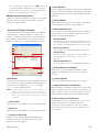
2 Device information
When a device that is registered for communication
with the DME-N Network Driver is selected in the
Target Device List, the communication parameters for
that device can be viewed and edited in the device
information fields.
[Device Name]
This is the name of the device selected in the Target
Device List. The initial default settings are “UNIT1”
through “UNIT256”, but the name can be edited as
required in this field.
[Device IP Address]
The IP address of the device selected in the Target
Device List can be set via these fields. Refer to page 7
for details on checking and setting its IP address.
n The IP address must be set properly or communication
with the device will not be possible.
[Device MAC Address]
The MAC (Media Access Control) address of the device
selected in the Target Device List can be set via these
fields. The MAC address of each device is permanently
assigned when the device is manufactured and cannot
be changed. The MAC address parameter is included to
prevent data from being sent to the wrong device if the IP
address in inadvertently set incorrectly. Refer to page 7
for details on checking its MAC address.
n The MAC address must be set properly or
communication with the device will not be possible.
n The MAC address of the connected device cannot be
changed.
[Device Port No.]
The MIDI port number of the device selected in the
Target Device List can be set via this menu. The MIDI
port number also functions as device ID number. It can
be set to “1” or “2” for DME64N/24N units. It should be
set to “1” for DME Satellite units.
n The MIDI port number must be set properly or
communication with the device will not be possible.
[Apply] Button
Click the [Apply] button after editing the Device Name,
Device IP Address, Device MAC Address, or Device Port
No. parameters to actually apply the changes. Also,
3
1
2
Pagina se încarcă...
Pagina se încarcă...
-
 1
1
-
 2
2
-
 3
3
-
 4
4
-
 5
5
-
 6
6
-
 7
7
-
 8
8
-
 9
9
-
 10
10
-
 11
11
-
 12
12
-
 13
13
-
 14
14
-
 15
15
-
 16
16
-
 17
17
-
 18
18
-
 19
19
-
 20
20
-
 21
21
-
 22
22


Yamaha DME Manual de utilizare
- Categorie
- Instrumente muzicale
- Tip
- Manual de utilizare
- Acest manual este potrivit și pentru
în alte limbi
- Türkçe: Yamaha DME Kullanım kılavuzu
- français: Yamaha DME Manuel utilisateur
- čeština: Yamaha DME Uživatelský manuál
- русский: Yamaha DME Руководство пользователя
- English: Yamaha DME User manual
- polski: Yamaha DME Instrukcja obsługi
- Deutsch: Yamaha DME Benutzerhandbuch
- italiano: Yamaha DME Manuale utente
- español: Yamaha DME Manual de usuario
- svenska: Yamaha DME Användarmanual
- dansk: Yamaha DME Brugermanual
- português: Yamaha DME Manual do usuário
- Nederlands: Yamaha DME Handleiding
Lucrări înrudite
-
Yamaha v4 Manual de utilizare
-
Yamaha DME Designer Manual de utilizare
-
-
-
-
-
-
-
-