Yamaha YST-SW015 Manualul proprietarului
- Categorie
- Difuzoare
- Tip
- Manualul proprietarului

YST-SW015
Subwoofer System
Enceinte a caisson de grave
OWNER’S MANUAL
MODE D’EMPLOI
BEDIENUNGSANLEITUNG
BRUKSANVISNING
MANUALE DI ISTRUZIONI
MANUAL DE INSTRUCCIONES
GEBRUIKSAANWIJZING
G
1-YST-SW015PRE-c 03.2.28, 7:16 PM1

● Nonskid pads
● Patins anti-dérapages
● Rutschfeste Auflagen
● Glidskyddsdynor
● Piedini antisdrucciolevoli
● Almohadillas antideslizantes
● Niet-glijdende steunen
UNPACKING Please check to make sure all listed items are included.
DEBALLAGE Veuillez vous assurer que tous les articles répertoriés sont bien présents.
AUSPACKEN Überprüfen Sie bitte, ob alle aufgelisteten Teile im Lieferumfang enthalten sind.
UPPACKNING Kontrollera att alla delar i förteckningen finns med.
DISIMBALLAGGIO Assicuratevi che tutti gli elementi elencati siano inclusi.
DESEMBALAJE Por favor asegúrese de que todos los elementos listados estén incluidos.
UITPAKKEN Controleer of alle hieronder afgebeelde voorwerpen in de doos zitten.
For U.K. customers
If the socket outlets in the home are not suitable for the plug
supplied with this appliance, it should be cut off and an
appropriate 3 pin plug fitted. For details, refer to the
instructions described below.
Note: The plug severed from the mains lead must be
destroyed, as a plug with bared flexible cord is hazardous if
engaged in a live socket outlet.
SPECIAL INSTRUCTIONS FOR U.K. MODEL
IMPORTANT:
THE WIRES IN MAINS LEAD ARE COLOURED IN
ACCORDANCE WITH THE FOLLOWING CODE:
Blue: NEUTRAL
Brown: LIVE
As the colours of the wires in the mains lead of this
apparatus may not correspond with the coloured
markings identifying the terminals in your plug, proceed
as follows: The wire which is coloured BLUE must be
connected to the terminal which is marked with the letter
N or coloured BLACK. The wire which is coloured
BROWN must be connected to the terminal which is
marked with the letter L or coloured RED. Making sure
that neither core is connected to the earth terminal of the
three pin plug.
1-YST-SW015PRE-c 03.2.28, 7:16 PM2

English
E-1
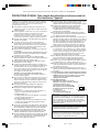
Please read the following operating precautions before use.
YAMAHA will not be held responsible for any damage
and/or injury caused by not following the cautions below.
●
To assure the finest performance, please read this manual
carefully. Keep it in a safe place for future reference.
● Install this unit in a cool, dry, clean place – away from
windows, heat sources, sources of excessive vibration,
dust, moisture and cold. Avoid sources of humming
(transformers, motors). To prevent fire or electrical
shock, do not expose this unit to rain or water.
● Never open the cabinet. If something drops into the set,
contact your dealer.
● The voltage to be used must be the same as that
specified on the rear panel. Using this unit with a higher
voltage than specified is dangerous and may cause a
fire and/or electric shock.
● To reduce the risk or fire or electric shock, do not expose
this unit to rain or moisture.
● Do not use force on switches, controls or connection
wires. When moving the unit, first disconnect the power
plug and the wires connected to other equipment. Never
pull the wires themselves.
●
When not planning to use this unit for a long period (i.e. vacation,
etc.), disconnect the AC power plug from the wall outlet.
● To prevent lightning damage, disconnect the AC power
plug when there is an electric storm.
● Since this unit has a built-in power amplifier, heat will
radiate from the rear panel. Place the unit apart from the
walls, allowing enough spaces above, behind and on
both sides of the unit to prevent fire or damage.
Furthermore, do not position with the rear panel facing
down on the floor or other surfaces.
<For U.K. and Europe models>
Be sure to allow spaces of at least 20 cm above, behind
and on both sides of the unit.
● Do not cover the rear panel of this unit with a
newspaper, a tablecloth, a curtain, etc. in order not to
obstruct heat radiation. If the temperature inside the unit
rises, it may cause fire, damage to the unit and/or
personal injury.
●
Do not place small metallic objects on this unit.
Otherwise, the object may fall, possibly causing an injury.
● Do not place the following objects on this unit:
Glass, china, etc.
If glass etc. falls by vibrations and breaks, it may cause
personal injury.
A burning candle etc.
If the candle falls by vibrations, it may cause fire and
personal injury.
A vessel with water in it
If the vessel falls by vibrations and water spills, it may cause
damage to the unit, and/or you may get an electric shock.
● Do not place this unit where foreign objects such as
water drips might fall. It might cause a fire, damage to
this unit, and/or personal injury.
● Never place a fragile object near the YST port of this
unit. If the object falls or drops by the air pressure, it may
cause damage to the unit and/or personal injury.
● Never put a hand or a foreign object into the YST port
located on the front of this unit. When moving this unit,
do not hold the port as it might cause personal injury
and/or damage to this unit.
● Never open the cabinet. It might cause an electric shock
since this unit uses a high voltage. It might also cause
personal injury and/or damage to this unit.
●
When using a humidifier, be sure to avoid condensation
inside this unit by allowing enough spaces around this unit
or avoiding excess humidification. Condensation might
cause a fire, damage to this unit, and/or electric shock.
● Super-bass frequencies reproduced by this unit may
cause a turntable to generate a howling sound. In such a
case, move this unit away from the turntable.
● This unit may be damaged if certain sounds are
continuously outputted at high volume level. For
example, if 20 Hz–50 Hz sine waves from a test disc,
bass sounds from electronic instruments, etc. are
continuously outputted, or when the stylus of a turntable
touches the surface of a disc, reduce the volume level to
prevent this unit from being damaged.
● If you hear distorted noise (i.e., unnatural, intermittent
“rapping” or “hammering” sounds) coming from this unit,
reduce the volume level. Extremely loud playing of a
movie soundtrack’s low frequency, bass-heavy sounds
or similarly loud popular music passages can damage
this speaker system.
● Vibration generated by super-bass frequencies may
distort images on a TV. In such a case, move this unit
away from the TV set.
● Do not attempt to clean this unit with chemical solvents
as this might damage the finish. Use a clean, dry cloth.
● Be sure to read the “TROUBLESHOOTING” section
regarding common operating errors before concluding
that the unit is faulty.
● Install this unit near the wall outlet and where the AC
power plug can be reached easily.
● Secure placement or installation is the owner’s
responsibility.
YAMAHA shall not be liable for any accident caused
by improper placement or installation of speakers.
● VOLTAGE SELECTOR
(For China, Korean and General models)
The voltage selector switch on the rear panel of this
unit must be set for your local main
voltage BEFORE plugging this unit
into the AC main supply. Voltages
are 110-120/220-240 V AC, 50/60 Hz.
Standby mode
If the POWER switch is set to the ON position and the
AUTO STANDBY switch is set to the HIGH or LOW
position, this unit turns into the standby mode when no
signal is received by this unit for 7 to 8 minutes.
In this state, this unit is designed to consume a very
small quantity of power.
This unit is not disconnected from the AC power source
as long as it is connected to the wall outlet, even if this
unit itself is turned off. In this state, this unit is designed
to consume a very small quantity of power.
This unit features a magnetically shielded design, but
there is still a chance that placing it too close to a TV set
might impair picture color. Should this happen, move this
unit away from the TV set.
CAUTION: Read this before operating your unit.
Thank you for selecting this YAMAHA Subwoofer System.
110V
–
120V 220V
–
240V
VOLTAGE
SELECTOR
2-SW015_G(E) cau(03.1.19)a 8/2/06, 6:39 PM1

E-2
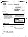
CONTENTS
UNPACKING ................ Inside of Front Cover
CAUTION .................................................. 1
FEATURES ............................................... 2
SPECIFICATIONS ................................... 2
PLACEMENT ............................................ 3
CONNECTIONS....................................... 4
CONTROLS AND THEIR
FUNCTIONS ............................................ 5
AUTOMATIC POWER-SWITCHING
FUNCTION............................................... 6
ADJUSTING THE SUBWOOFER
BEFORE USE .......................................... 7
Frequency characteristics...................... 8
ADVANCED YAMAHA ACTIVE
SERVO TECHNOLOGY ........................... 9
TROUBLESHOOTING ............................ 10
FEATURES
● This subwoofer system employs Advanced Yamaha
Active Servo Technology which YAMAHA has developed
for reproducing higher quality super-bass sound. (Refer to
page 9 for details on Advanced Yamaha Active Servo
Technology.) This super-bass sound adds a more
realistic, theater-in-the-home effect to your stereo system.
● For the effective use of the subwoofer, the subwoofer’s
super-bass sound should be matched to the sounds of
your main speakers. You can create the best sound
quality for various listening conditions by using the HIGH
CUT control and the PHASE switch.
● The Automatic power-switching function saves you the
trouble of pressing the STANDBY/ON button to turn the
power on or turn it to the STANDBY mode.
● You can select bass effect suitable for the source by
using the B.A.S.S. button.
QD-Bass Technology
QD-Bass (Quatre Dispersion Bass) technology uses
square, pyramid-shaped reflective plates to radiate the
sound in four horizontal directions.
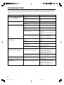
SPECIFICATIONS
Type ............... Advanced Yamaha Active Servo Technology
Magnetic shielding type
Driver ....................................... 16 cm (6-1/2”) cone woofer
Amplifier Output .................................................. 70 W/5Ω
Frequency Response ............................... 30 Hz to 200 Hz
Power Supply
U.S.A. and Canada models .................... AC 120V, 60 Hz
U.K. and Europe models ........................ AC 230V, 50 Hz
Australia model....................................... AC 240V, 50 Hz
China, Korean and General models
....................................... AC 110-120/220-240V, 50/60 Hz
Power Consumption ................................................. 70 W
Standby Power Consumption ................................. 0.8 W
Dimensions (W x H x D) ..... 280 mm x 325 mm x 320 mm
(11” x 12-13/16” x 12-5/8”)
Weight ................................................ 9.2 kg (20 lbs. 4 oz.)
* Specifications are subject to change without notice due to
product improvements.
2-SW015(E) (03.1.19)a 03.2.28, 7:16 PM2

English
E-3
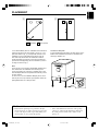
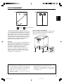
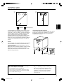
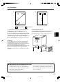
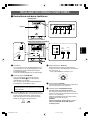
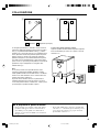
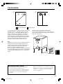
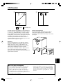
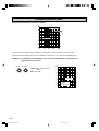
PLACEMENT
It is recommended to place the subwoofer on the outside of
either the right or the left main speaker. (See fig. Å .) The
placement shown in fig. ı is also possible, however, if the
subwoofer system is placed directly facing the wall, the
bass effect may die because the sound from it and the
sound reflected by the wall may cancel out each other. To
prevent this from happening, face the subwoofer system at
an angle as shown in fig. Å.
Note
There may be a case that you cannot obtain enough super-
bass sounds from the subwoofer when listening in the
center of the room. This is because “standing waves” have
been developed between two parallel walls and they cancel
the bass sounds.
In such a case, face the subwoofer obliquely to the wall. It
also may be necessary to break up the parallel surfaces by
placing bookshelves etc. along the walls.
( : subwoofer, : main speaker)
Use the non-skid pads
Put the provided non-skid pads at the four corners on the
bottom of the subwoofer to prevent the subwoofer from
moving by vibrations etc.
ı
Å
SUBWOOFER SYSTEM YST-SW015
S
TA
N
D
B
Y/O
N
B
.A.S
.S.
H
IG
H C
U
T
5
0
–
1
50Hz
V
O
LU
M
E
0
–
10
■ About this manual
• This manual is printed prior to production. Design
and specifications are subject to change in part for the
reason of the improvement in operativity ability, and
others. In this case, the product has priority.
• Some of the illustrations and names of the package
contents etc. written in this manual may differ from
the actual products and the names written on the
package etc.
2-SW015(E) (03.1.19)a 03.2.28, 7:16 PM3

E-4
SPLIT SUBWOOFER
SUBWOOFER
(LOW PASS)
INPUT
/MONO
OFF LOW HIGH
AUTO
STANDBY
NORM REV
PHASE
POWER
ON
OFF
110V
–
120V 220V
–
240V
VOLTAGE
SELECTOR
INPUT
/MONO
OFF LOW HIGH
AUTO
STANDBY
NORM REV
PHASE
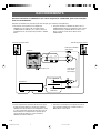
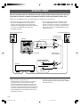
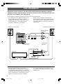
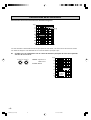
Notes
● Some amplifiers have line output terminals labeled PRE
OUT. When you connect the subwoofer to the PRE OUT
terminals of the amplifier, make sure that the amplifier
has at least two sets of PRE OUT terminals. If the
amplifier has only one set of PRE OUT terminals, do not
connect the subwoofer to the PRE OUT terminals.
● When connecting to a monaural line output terminal of
the amplifier, connect the L/MONO INPUT terminal.
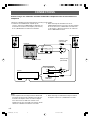
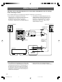
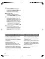
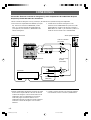
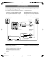
CONNECTIONS
Caution: Plug in the subwoofer and other audio/video components after all connections are
completed.
Subwoofer
Amplifier
● To connect with a YAMAHA DSP amplifier (or AV
receiver), connect the SUBWOOFER (or LOW PASS etc.)
terminal on the rear of the DSP amplifier (or AV receiver)
to the L/MONO INPUT terminal of the subwoofer.
Connect the subwoofer to the line output (pin jack) terminal(s) of the amplifier.
● When connecting the subwoofer to the SPLIT
SUBWOOFER terminals on the rear of the DSP amplifier,
be sure to connect the L/MONO INPUT terminal to the
“L” side and the R INPUT terminal to the “R” side of the
SPLIT SUBWOOFER terminals.
Audio pin cable
(not included)
Left main speaker
Right main speaker
To AC outlet
Subwoofer cable
(not included)
2-SW015(E) (03.1.19)a 03.2.28, 7:16 PM4

English
E-5
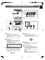
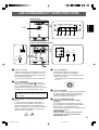
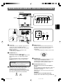
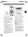
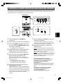
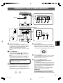
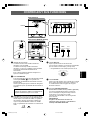
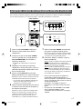
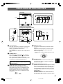
CONTROLS AND THEIR FUNCTIONS
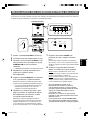
1 Power indicator
Lights up in green while the subwoofer is on.
Lights up in red while the subwoofer is set in the
standby mode by the operation of the automatic power-
switching function.
Goes off when the subwoofer is set in the standby
mode.
2 STANDBY/ON button
Press this button to turn on the power when the
POWER (
7) switch is set in the ON position. (The
power indicator lights up in green.)
Press again to set the subwoofer in the standby mode.
(The power indicator goes off.)
Standby mode
The subwoofer is still using a small amount of power
in this mode.
3 B.A.S.S. (Bass Action Selector System) button
When this button is pressed in to the MUSIC position,
the bass sound in audio software is well reproduced.
By pressing the button again so that it pops out at the
MOVIE position, the bass sound in video software is
well reproduced.
INPUT
/MONO
OFF LOW HIGH
AUTO
STANDBY
NORM REV
PHASE
POWER
ON
OFF
110V
–
120V 220V
–
240V
VOLTAGE
SELECTOR
SUBWOOFER SYSTEM YST-SW015
STANDBY/ON B.A.S.S. HIGH CUT
50
–
150Hz
VOLUME
0
–
10
INPUT
/MONO
OFF LOW HIGH
AUTO
STANDBY
NORM REV
PHASE
SUBWOOFER SYSTEM YST-SW015
STANDBY/ON B.A.S.S. HIGH CUT
50
–
150Hz
VOLUME
0
–
10
POWER
ON
OFF
110V
–
120V 220V
–
240V
VOLTAGE
SELECTOR
24513
98 0
7
6
Rear panel (General model)
Front panel
Port
MOVIE MUSIC
4 HIGH CUT control
Adjusts the high frequency cut off point.
Frequencies higher than the frequency selected by this
control are all cut off (and no output).
* One graduation of this control represents 10 Hz.
5 VOLUME control
Adjusts the volume level. Turn the control clockwise to
increase the volume, and counterclockwise to
decrease the volume.
6 VOLTAGE SELECTOR switch
(For China, Korean and General models)
If the preset setting of the switch is incorrect, set the
switch to the proper voltage range (220V-240V or
110V-120V) of your area.
Consult your dealer if you are unsure of the correct
setting.
WARNING
Be sure to unplug the subwoofer before setting the
VOLTAGE SELECTOR switch correctly.
50 Hz
60 Hz
70 Hz
80 Hz
90 Hz
140 Hz
130 Hz
120 Hz
110 Hz
100 Hz
150 Hz
2-SW015(E) (03.1.19)a 03.2.28, 7:17 PM5

E-6
7 POWER switch
Normally, set this switch to the ON position to use the
subwoofer. In this state, you can turn on the subwoofer
or turn the subwoofer into the standby mode by
pressing the STANDBY/ON (
2) button. Set this switch
to the OFF position to completely cut off the
subwoofer’s power supply from the AC line.
8 INPUT terminals
Used to input line level signals from the amplifier.
(Refer to “CONNECTIONS” for details.)
9 AUTO STANDBY (HIGH/LOW/OFF) switch
This switch is originally set to the OFF position. By
setting this switch to the HIGH or LOW position, the
subwoofer’s automatic power-switching function
operates as described below. If you do not need this
function, leave this switch in the OFF position.
* Make sure to change the setting of this switch only
when the subwoofer is set in the standby mode by
pressing the STANDBY/ON (
2) button.
0 PHASE switch
Normally this switch is to be set to the REV (reverse)
position. However, according to the listening condition
or your preference, there may be a case when better
sound quality is obtained by setting this switch to the
NORM (normal) position. Select the better position by
monitoring the sound.
AUTOMATIC POWER-SWITCHING FUNCTION
IIf the source being played is stopped and the input signal is
cut off for 7 to 8 minutes, the subwoofer automatically
switches to the standby mode. (When the subwoofer
switches to the standby mode by the automatic power-
switching function, the power indicator lights up in red.)
When you play a source again, the power of the subwoofer
turns on automatically by sensing audio signals input to the
subwoofer.
This function operates by sensing a certain level of low
frequency input signal. Usually set the AUTO STANDBY
switch to the LOW position. However, if this function does
not operate smoothly, set the switch to the HIGH position. In
the HIGH position, the power will turn on even with a low
level of input signal. But please be aware that the subwoofer
may not switch to the standby mode when there is an
extremely low input signal.
* The power might turn on unexpectedly by sensing noise
from other appliances. If that occurs, set the AUTO
STANDBY switch to the OFF position and use the
STANDBY/ON button to switch the power between on
and in the standby mode manually.
* This function detects the low-frequency components
below 200 Hz of the input signals (i.e., the explosion in
the action movie, the sound of the bass guitar or the bass
drum, etc.).
* The minutes required to switch the subwoofer to the
standby mode might change by sensing noise from other
appliances.
This function is available only when the power of the
subwoofer is on (by pressing the STANDBY/ON button).
2-SW015(E) (03.1.19)a 03.2.28, 7:17 PM6

English
E-7
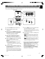
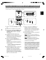
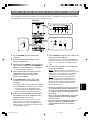
1 Set the VOLUME control to minimum (0).
2 Turn on the power of all the other
components.
3 Make sure that the POWER switch is set to
the ON position, then press the STANDBY/
ON button to turn on the subwoofer.
* The Power indicator lights up in green.
4 Play a source containing low-frequency
components and adjust the amplifier’s
volume control to the desired listening level.
5 Adjust the HIGH CUT control to the position
where the desired response can be
obtained.
Normally, set the control to the main speaker’s rated
minimum reproducible frequency*.
* The main speaker’s rated minimum reproducible
frequency can be looked up in the speakers’ catalog
or owner’s manual.
6 Increase the volume gradually to adjust the
volume balance between the subwoofer and
the main speakers.
Normally, set the control to the level where you can
obtain a little more bass effect than when the subwoofer
is not used. If the desired response cannot be obtained,
adjust the HIGH CUT control and the VOLUME control
again.
Before using the subwoofer, adjust the subwoofer to obtain the optimum volume and tone balance between the subwoofer and
the main speakers by following the procedures described below.
7 Set the PHASE switch to the position which
gives you the better bass sound.
Normally, set the switch to the REV (reverse) position. If
the desired response cannot be obtained, set the switch
to the NORM (normal) position.
8 Select “MOVIE” or “MUSIC” according to the
played source.
MOVIE: When a movie type source is played, the low-
frequency effects are enhanced to allow the listener
enjoy more powerful sound. (The sound will be thicker
and deeper.)
MUSIC: When an ordinary music source is played, the
excessive low-frequency components are cut off to
make the sound clearer. (The sound will be lighter and
reproduces the melody line more clearly.)
• Once the volume balance between the subwoofer and
the main speakers is adjusted, you can adjust the
volume of your whole sound system by using the
amplifier’s volume control.
However, if you change the main speakers to others,
you must make this adjustment again.
• For adjusting the VOLUME control, the HIGH CUT
control and the PHASE switch, refer to “Frequency
characteristics” on the next page.
ADJUSTING THE SUBWOOFER BEFORE USE
INPUT
/MONO
OFF LOW HIGH
AUTO
STANDBY
NORM REV
PHASE
POWER
ON
OFF
110V
–
120V 220V
–
240V
VOLTAGE
SELECTOR
SUBWOOFER SYSTEM YST-SW015
STANDBY/ON B.A.S.S. HIGH CUT
50
–
150Hz
VOLUME
0
–
10
INPUT
/MONO
OFF LOW HIGH
AUTO
STANDBY
NORM REV
PHASE
SUBWOOFER SYSTEM YST-SW015
STANDBY/ON B.A.S.S. HIGH CUT
50
–
150Hz
VOLUME
0
–
10
POWER
ON
OFF
1, 6583
3
7
Rear panel
Front panel
2-SW015(E) (03.1.19)a 03.2.28, 7:17 PM7

E-8
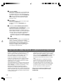
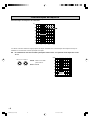
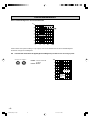
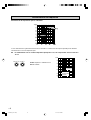
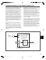
This subwoofer’s frequency characteristics
EX. When combined with an 3.5” or 4” (8 cm or 10 cm) acoustic suspension, 2 way system main
speakers
The figures below show the optimum adjustment of each control and the frequency characteristics when this subwoofer is
combined with a typical main speaker system.
Frequency characteristics
100
PHASE–Set to the REV
(reverse) position.
B.A.S.S.–MOVIE
HIGH CUT50
–
150Hz VOLUME
0
–
10
20 50 100 200 500Hz
40
50
60
70
80
90
100 dB
YST-SW005
YST-SW015
Main
speaker’s
response
2-SW015(E) (03.1.19)a 03.2.28, 7:17 PM8

English
E-9
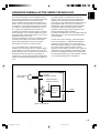
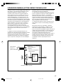
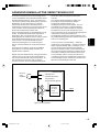
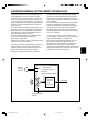
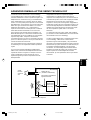
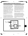
ADVANCED YAMAHA ACTIVE SERVO TECHNOLOGY
The theory of Yamaha Active Servo Technology has been
based upon two major factors, the Helmholtz resonator and
negative-impedance drive. Active Servo Processing
speakers reproduce the bass frequencies through an “air
woofer”, which is a port or opening in the speaker’s cabinet.
This opening is used instead of, and performs the functions
of, a woofer in a conventionally designed speaker system.
Thus, signals of low amplitude within the cabinet can,
according to the Helmholtz resonance theory, be outputted
from this opening as waves of great amplitude if the size of
the opening and the volume of the cabinet are in the correct
proportion to satisfy a certain ratio.
In order to accomplish this, moreover, the amplitudes within
the cabinet must be both precise and of sufficient power
because these amplitudes must overcome the “load”
presented by the air that exists within the cabinet.
Thus it is this problem that is resolved through the
employment of a new design in which the amplifier supplies
special signals. If the electrical resistance of the voice coil
could be reduced to zero, the movement of the speaker unit
would become linear with respect to signal voltage. To
accomplish this, a special negative-impedance output-drive
amplifier for subtracting output impedance of the amplifier is
used.
By employing negative-impedance drive circuits, the
amplifier is able to generate precise, low-amplitude, low-
frequency waves with superior damping characteristics.
These waves are then radiated from the cabinet opening as
high-amplitude signals. The system can, therefore, by
employing the negative-impedance output drive amplifier
and a speaker cabinet with the Helmholtz resonator,
reproduce an extremely wide range of frequencies with
amazing sound quality and less distortion.
The features described above, then, are combined to be the
fundamental structure of the conventional Yamaha Active
Servo Technology.
Our new Active Servo Technology — Advanced Yamaha
Active Servo Technology — adopted Advanced Negative
Impedance Converter (ANIC) circuits, which allows the
conventional negative impedance converter to dynamically
vary in order to select an optimum value for speaker
impedance variation. With this new ANIC circuits, Advanced
Yamaha Active Servo Technology can provide more stable
performance and improved sound pressure compared with
the conventional Yamaha Active Servo Technology, resulting
in more natural and dynamic bass reproduction.
High-amplitude
bass sound
Cabinet
Port
Air woofer
(Helmholtz resonator)
Active Servo
Processing
Amplifier
Signals
Signals of low amplitude
Advanced Negative-
impedance Converter
2-SW015(E) (03.1.19)a 03.2.28, 7:17 PM9

E-10
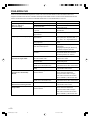
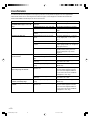
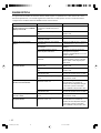
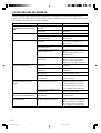
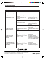
TROUBLESHOOTING
Refer to the chart below when this unit does not function properly. If the problem you are experiencing is not listed below or if
the instructions given below do not help, disconnect the power cable and contact your authorized YAMAHA dealer or service
center.
Problem
Power is not supplied even
though the STANDBY/ON button
is set to the ON position.
No sound.
Sound level is too low.
The subwoofer does not turn on
automatically.
The subwoofer does not turn into
the standby mode automatically.
The subwoofer turns into the
standby mode unexpectedly.
The subwoofer turns on
unexpectedly.
What to Do
Connect it securely.
Set the POWER switch to the ON
position.
Turn the VOLUME control to the right.
Connect them securely.
Connect them correctly, that is L (left) to
L, R (right) to R, “+” to “+” and “–” to “–”.
Set the switch to the other position.
Play a source sound with bass
frequencies.
Set the HIGH CUT control to a higher
position.
Reposition the subwoofer or break up
the parallel surface by placing
bookshelves etc. along the walls.
Set the POWER switch to the ON
position.
Set the STANDBY/ON button to the ON
position.
Set the AUTO STANDBY switch to the
“HIGH” or “LOW” position.
Set the AUTO STANDBY switch to the
“HIGH” position.
Move the subwoofer further away from
such appliances and/or reposition the
connected speaker cables.
Otherwise, set the AUTO STANDBY
switch to the “OFF” position.
Set the AUTO STANDBY switch to the
“HIGH” or “LOW” position.
Set the AUTO STANDBY switch to the
“HIGH” position.
Move the subwoofer farther away from
such appliances and/or reposition the
connected speaker cables.
Otherwise, set the AUTO STANDBY
switch to the “OFF” position.
Cause
The power plug is not securely
connected.
The POWER switch is set to the OFF
position.
The VOLUME control is set to 0.
Speaker cables are not connected
securely.
Speaker cables are not connected
correctly.
Setting of the PHASE switch is not
proper.
A source sound with few bass
frequencies is played.
It is influenced by standing waves.
The POWER switch is set to the OFF
position.
The STANDBY/ON button is set to the
OFF position.
The AUTO STANDBY switch is set to
the OFF position.
The level of input signal is too low.
There is an influence of noise
generated from external appliances etc.
The AUTO STANDBY switch is set to
the OFF position.
The level of input signal is too low.
There is an influence of noise
generated from external appliances etc.
2-SW015(E) (03.1.19)a 03.2.28, 7:17 PM10

Français
F-1
Veuillez lire les précautions suivantes avant toute utilisation.
YAMAHA ne se tiendra pas responsable d’aucun dommage
et/ou d’aucune blessure causés en ne suivant pas les
avertissements ci-sessous.
●
Pour garantir les meilleures performances possibles, lire ce
manuel avec attention. Le garder dans un endroit sûr pour une
utilisation ultérieure.
●
Installer l’appareil dans un endroit frais, sec et propre, loin de fenêtres,
sources de chaleur et d’endroits où les vibrations, la poussière,
l’humidité ou le froid sont importants. Eviter les sources de
bourdonnements (transformateurs, moteurs). Pour éviter les incendies
ou électrocution, ne pas exposer l’appareil à la pluie ni à l’humidité.
●
Ne jamais ouvrir le coffret. Si un objet pénètre dans l’appareil,
contacter son revendeur.
●
Le voltage à utiliser doit être le même que celui spécifié sur le
panneau arrière. Utiliser l’appareil avec un plus haut voltage que
spécifié est dangeraux et peut causer un feu et/ou une électrocution.
●
Afin d’éviter tout risque d’incendie ou d’électrocution, ne pas
exposer l’appareil à la pluie ni à l’humidité.
●
Ne pas forcer les commutateurs, les touches ou les câbles de
raccordement.
Lors du déplacement de l’appareil, d’abord débrancher la prise
d’alimentation et les câbles le raccordant à d’autres appareils.
Ne jamais tirer sur les cordons.
●
Lorsqu’on prévoit de ne pas utiliser cet appareil pendant
longtemps (pendant les vacances, par exemple), débrancher le
cordon d’alimentation CA de la prise murale.
●
Pour prévenir tout dégât dû à la foudre, débrancher la prise
d’alimentation CA en cas d’orage.
●
Cet appareil possédant un amplificateur intégré, de la chaleur sera
irradiée par le panneau arrière. Par conséquent, placer l’appareil à une
certaine distance des murs, en laissant suffisamment d’espace au-
dessus, derrière et des deux côtés de l’appareil afin d’éviter tout risque
de dommage ou d’incendie. Ne pas positionner non plus cet appareil
dos au plancher ou à une autre surface.
<Modèles pour le Royaume-Uni et l’Europe>
Laisser un espace d’au moins 20 cm au-dessus, derrière et
des deux côtés de l’appareil.
●
Ne pas couvrir le panneau arrière de cet appareil avec un journal, une
nappe, un rideau, etc., afin de ne pas empêcher le rayonnement de
chaleur. Si la température s’élève à l’intérieur de l’appareil, ceci risque
de causer un incendie, d’endommager l’appareil et/ou de provoquer
des blessures corporelles.
●
Ne pas placer de petits objets métalliques sur l’appareil. Ils
pourraient tomber et risqueraient de causer une blessure.
●
Ne placez pas les objets suivants sur l’appareil:Verres,
porcelaine, etc.
Si les verres, etc., tombent sous l’effet des vibrations et se
rompent, ceci risque de causer des blessures.
Une bougie allumée, etc.
Si la bougie tombe sous l’effet des vibrations, ceci risque de
causer un incendie et des blessures.
Un récipient contenant de l’eau
Si le récipient tombe sous l’effet des vibrations et que l’eau
se répand, ceci risque d’endommager l’appareil et/ou de
causer une électrocution.
●
Ne pas placer l’appareil dans un endroit où des corps étrangers
comme des gouttes d’eau peuvent tomber. Ceci peut causer un
feu, des dommages à l’appareil et/ou une blessure corporelle.
●
Ne jamais placer d’objet fragile à proximité du port YST de
l’appareil. Si l’objet tombe à cause de la pression d’air, il peut
entraîner des dommages à l’appareil et/ou des blessures.
●
Ne jamais introduire la main ou tout corps étranger dans le port
YST situé sur l’avant de l’appareil. Lors du déplacement de cet
appareil, ne pas le tenir par le port, cela peut entraîner des
blessures et/ou endommager l’appareil.
●
Ne jamais ouvrir le coffret. Cet appareil utilisant un haut voltage,
cela peut entraîner une décharge électrique. Cela peut
également entraîner des blessures et/ou endommager l’appareil.
●
En utilisant un humidificateur, éviter la condensation
à l’intérieur de l’appareil en libérant la place autour
de l’appareil ou en évitant l’humidification extrême.
La condensation peut causer un feu, des dommages à
l’appareil et/ou une électrocution.
●
Les sons de très basse fréquence produits par cet appareil
peuvent provoquer un sifflement sur le tourne-disque. Dans ce
cas, éloigner cet appareil du tourne-disque.
●
Cet appareil pourra se trouver endommagé si certains sons se
trouvent émis à haut volume de façon continue. Par exemple, si
des ondes sinusoïdales de 20 – 50 Hz d’un disque d’essai, des
sons de basse fréquence d’un instrument électronique, etc.
sont émis continuellement, ou lorsque l’aiguille d’un tourne-
disque est posée sur un disque en rotation, il faut réduire le
volume sonore afin que cet appareil ne soit pas endommagé.
●
Si une distorsion se fait entendre (par exemple des petits coups
secs intermittents ou un “martèlement”) sur cet appareil, diminuer
le niveau sonore. La lecture à très haut volume des sons de basse
ou des sons de basses fréquences de la bande sonore d’un film,
ou de passages de musique populaire de forte intensité, sont
susceptibles d’endommager ce système d’enceintes.
●
Les vibrations provenant des fréquences très basses peuvent
causer de la distorsion sur l’image d’un téléviseur placé à
proximité. Si c’est la cas, éloigner l’appareil du téléviseur.
●
Ne pas essayer de nettoyer l’appareil avec des diluants chimiques,
ceci endommagerait le fini. Utiliser un chiffon propre et sec.
●
Bien lire la section “EN CAS DE DIFFICULTES” concernant les
erreurs de fonctionnement communes avant de conclure que
votre appareil est en panne.
●
Installez cet appareil à proximité de la prise secteur et à un
emplacement où la fiche du câble d’alimentation est facilement
accessible.
●
Le propriétaire du système est entièrement responsable du
bon positionnement et de la bonne installation du système.
YAMAHA décline toute responsabilité en cas d’accident
causé par un positionnement ou une installation
inadéquats des enceintes.
●
VOLTAGE SELECTOR
(Interrupteur de sélection de tension)
(Modèles pour la Chine, la Corée et général)
Le sélecteur de tension sur le
panneau arrière de cet appareil doit
être réglé sur la tension locale AVANT
de brancher l’appareil sur une prise
de courant CA.
Les tensions sont de
110-120/220-240 V CA, 50/60 Hz.
Mode veille
Si l’interrupteur POWER est mis sur la position ON et le
commutateur AUTO STANDBY sur la position HIGH ou
LOW, cet appareil passe en mode veille lorsqu’aucun
signal ne parvient à cet appareil pendant 7 ou 8 minutes.
Dans cet état, l’appareil consomme une très faible
quantité de courant.
Cet appareil n’est pas déconnecté du secteur tant qu’il
reste branché á la prise de courant. En pareil cas, celui-
ci consomme une faible quantité d’électricité.
Bien que cet appareil soit doté d’un blindage
magnétique, il est possible que la couleur des images
d’un téléviseur placé à proximité en soit affectée. Dans
ce cas, éloigner cet appareil du téléviseur.
PRECAUTIONS D’USAGE: Tenir compte des précautions ci-dessous avant de
faire fonctionner l’appareil.
Nous vous remercions d’avoir porté votre choix sur ce subwoofer de YAMAHA.
110V
–
120V 220V
–
240V
VOLTAGE
SELECTOR
3-SW015 G(F) Cau(03.2.28)a 8/25/06, 1:18 PM1

F-2
TABLE DES MATIERES
DEBALLAGE
........................Intérieur du couvercle avant
PRECAUTIONS D’USAGE .......................1
CARACTERISTIQUES ............................. 2
CARACTERISTIQUES TECHNIQUES
..... 2
POSITIONNEMENT .................................. 3
RACCORDEMENTS .................................4
LES COMMANDES ET LEURS
FONCTIONS ............................................ 5
FONCTION DE COMMUTATION DE
L’ALIMENTATION AUTOMATIQUE ......... 6
REGLAGE DU SUBWOOFER AVANT
L’UTILISATION ......................................... 7
Caractéristiques de fréquence .............. 8
ADVANCED YAMAHA ACTIVE SERVO
TECHNOLOGY ........................................ 9
EN CAS DE DIFFICULTES..................... 10
CARACTERISTIQUES
● Ce subwoofer utilise la Advanced Yamaha Active Servo
Technology mise au point par YAMAHA pour une
reproduction des basses fréquences de meilleure qualité.
(Reportez-vous à la page 9 pour plus de détails sur la
technologie Advanced Yamaha Active Servo Technology.)
Le son à super basses ajoute plus de réalisme, et un
effet cinéma-à-domicile à votre système stéréo.
● Pour utiliser au mieux les possibilités de ce subwoofer,
les basses fréquences de ce subwoofer doivent être
harmonisées avec les sons des enceintes principales. De
plus, il est possible d’optimiser la qualité sonore suivant
les conditions d’écoute au moyen de la commande HIGH
CUT et du commutateur PHASE.
● La fonction de commutation d’alimentation automatique
Technologie QD-Bass
La technologie QD-Bass (Quatre Dispersion Bass)
utilise des plaques réfléchissantes carrées, de forme
pyramidale pour rayonner le son dans les quatre
directions horizontales.
évite d’appuyer sur la touche STANDBY/ON pour allumer
et pour mettre l’appareil en mode STANDBY.
● Il est possible de sélectionner un effet de basses
convenant à la source à l’aide de la touche B.A.S.S.
CARACTERISTIQUES TECHNIQUES
Type ............... Advanced Yamaha Active Servo Technology
Type à blindage magnétique
Pilote .............................. Enceinte grave en cône de 16 cm
Sortie de l’amplificateur ....................................... 70W/5Ω
Réponse en fréquence .............................. 30 Hz à 200 Hz
Alimentation
Modèles pour les Etats-Unis et le Canada
.................................................................. CA 120V, 60 Hz
Modèles pour le Royaume-Uni et l’Europe
.................................................................. CA 230V, 50 Hz
Modèle pour l’Australie .......................... CA 240V, 50 Hz
Modèles pour la Chine, la Corée et général
....................................... CA 110-120/220-240V, 50/60 Hz
Consommation ............................................................ 70W
Consommation en veille ............................................ 0,8W
Dimensions (L x H x P) ....... 280 mm x 325 mm x 320 mm
Poids ......................................................................... 9,2 kg
* Noter que toutes les caractéristiques techniques sont
modifiables sans préavis.
3-SW015(F)(03.2.28)a 03.2.28, 7:17 PM2

Français
F-3
POSITIONNEMENT
Il est recommandé de placer le subwoofer sur le côté
extérieur de l’enceinte principale droite ou gauche. (Voir fig.
Å.) Il est également possible de positionner les enceintes
comme indiqué sur la fig. ı; cependant, si le subwoofer est
placé directement contre le mur, l’effet de basse pourra se
trouver supprimé car le son émis par l’enceinte et le son
renvoyé par le mur s’annuleront mutuellement. Pour éviter
ce problème, placer le subwoofer à angle oblique par
rapport au mur, comme indiqué sur la fig. Å.
Remarque
Les sons de très basses fréquences du subwoofer peuvent
quelquesfois être trop faiblement perçus à partir d’une
position d’écoute en milieu de pièce. Les ondes renvoyées
par deux murs parallèles peuvent en effet s’annuler
mutuellement et supprimer les sons de basses.
Dans un tel cas, diriger le subwoofer obliquement par
rapport au mur. Il peut être également nécessaire de
modifier le parallélisme des surfaces murales en plaçant
des étagères, etc. le long des murs.
( : subwoofer, : enceintes principales)
ı
Å
Utiliser les tampons anti-dérapage
Mettre les tampons anti-dérapage fournis aux quatre coins
du bas du subwoofer afin d’empêcher le subwoofer de
bouger sous l’effet des vibrations, etc.
S
U
B
W
O
O
F
E
R
S
Y
S
T
E
M
Y
S
T
-S
W
0
1
5
STANDBY/ON
B.A.S.S.
HIGH CUT
5
0
–
1
5
0
H
z
VOLUME
0
–
1
0
■ Quelques ¡mots sur ce mode d’emploi
• Ce mode d’emploi a été imprimé avant la fabrication
du système. La présentation et les caractéristiques de
ce dernier peuvent être modifiées pour des raisons de
simplicité de fonctionnement, ou des raisons
similaires. Ce sont des cas où le système a la priorité
sur le mode d’emploi.
• Certaines illustrations et noms du contenu de
l’emballage, etc., apparaissant dans ce mode d’emploi
peuvent différer du produit réel et de ceux qui figurent
sur l’emballage, etc.
3-SW015(F)(03.2.28)a 03.2.28, 7:17 PM3

F-4
SPLIT SUBWOOFER
SUBWOOFER
(LOW PASS)
INPUT
/MONO
OFF LOW HIGH
AUTO
STANDBY
NORM REV
PHASE
POWER
ON
OFF
110V
–
120V 220V
–
240V
VOLTAGE
SELECTOR
INPUT
/MONO
OFF LOW HIGH
AUTO
STANDBY
NORM REV
PHASE
Remarques
● Certains amplificateurs possèdent des bornes de sortie
de ligne nommées PRE OUT. Lorsque l’on raccorde le
subwoofer aux bornes PRE OUT de l’amplificateur, veiller
à ce que l’amplificateur possède au moins deux jeux de
bornes PRE OUT. Si l’amplificateur ne possède qu’un
seul jeu de bornes PRE OUT, ne pas raccorder le
subwoofer aux bornes PRE OUT.
RACCORDEMENTS
Attention: Brancher le subwoofer et les autres composants audio/vidéo après avoir accompli
tous les raccordements.
Raccorder le subwoofer à la (aux) borne(s)de sortie de ligne (prise à broche) de l’amplificateur.
Subwoofer
Amplificateur
●
Pour effectuer le raccordement à un amplificateur
YAMAHA DSP (ou récepteur AV), raccorder la borne
SUBWOOFER (ou LOW PASS, etc.) située à l’arrière de
l’amplificateur DSP (ou récepteur AV) à la borne L/MONO
INPUT.
● Lorsqu’on raccorde le subwoofer aux bornes SPLIT
SUBWOOFER à l’arrière de l’amplificateur DSP, veiller à
raccorder la borne L/MONO INPUT au côté “L” et les
bornes R INPUT au côté “R” des bornes SPLIT
SUBWOOFER.
Câble pour subwoofer
(non compris)
Enceinte principale gauche
Enceintes principale droite
● Pour faire un raccordement à une borne de sortie de
ligne mono de l’amplificateur, raccorder la borne L/
MONO INPUT à cette borne.
Câble de fiche
Cinch audio
(non compris)
Vers une prise CA
3-SW015(F)(03.2.28)a 03.2.28, 7:17 PM4

Français
F-5
1 Voyant d’alimentation
S’allume en vert lorsque le subwoofer est sous tension.
S’allume en rouge lorsque le subwoofer est mis en
mode veille par action de la fonction de commutation
de l’alimentation automatique.
S’éteint lorsque le subwoofer est mis en mode veille.
2 Touche STANDBY/ON
Appuyez sur cette touche pour allumer l’appareil
lorsque le commutateur POWER (
7) est en position
ON. (Le témoin d’alimentation s’allume en vert.)
Appuyez de nouveau dessus pour mettre le subwoofer
en mode veille. (Le témoin d’alimentation s’éteint.)
Mode veille
Le subwoofer consomme encore un peu de courant
dans ce mode.
3 Touche B.A.S.S. (Système de sélection d’action de
basses)
Les sons de basses des logiciels audio seront
particulièrement bien reproduits si cette touche est
placée en position MUSIC. Si l’on appuie dessus
encore une fois de façon à la faire ressortir en position
MOVIE, ce seront les sons de basses des logiciels
vidéo qui seront bien reproduits.
4 Commande HIGH CUT
Ajuste le point de coupure haute fréquence.
Les fréquences supérieures à la fréquence
sélectionnée à l’aide de cette commande sont toutes
coupées (pas de sortie).
* Une graduation de cette commande correspond
à 10 Hz.
5 Commande VOLUME
Régle le niveau de volume. Tourner la commande dans
le sens des aiguilles d’une montre pour augmenter
le niveau de volume, et dans le sens inverse des
aiguilles d’une montre pour le diminuer.
6 Interrupteur VOLTAGE SELECTOR
(Modèles pour la Chine, la Corée et général
seulement)
Si le réglage d’usine de l’interrupteur est incorrect,
placer l’interrupteur sur la plage de tension correcte
(220V-240V ou 110-120V) pour votre pays.
Si vous avez des doutes concernant le réglage correct,
consultez votre revendeur.
AVERTISSEMENT
Veiller absolument à débrancher le subwoofer
avant de régler correctement l’interrupteur
VOLTAGE SELECTOR.
LES COMMANDES ET LEURS FONCTIONS
INPUT
/MONO
OFF LOW HIGH
AUTO
STANDBY
NORM REV
PHASE
POWER
ON
OFF
110V
–
120V 220V
–
240V
VOLTAGE
SELECTOR
SUBWOOFER SYSTEM YST-SW015
STANDBY/ON B.A.S.S. HIGH CUT
50
–
150Hz
VOLUME
0
–
10
INPUT
/MONO
OFF LOW HIGH
AUTO
STANDBY
NORM REV
PHASE
SUBWOOFER SYSTEM YST-SW015
STANDBY/ON B.A.S.S. HIGH CUT
50
–
150Hz
VOLUME
0
–
10
POWER
ON
OFF
110V
–
120V 220V
–
240V
VOLTAGE
SELECTOR
24513
98 0
7
6
Panneau arrière (Modèle général)
Panneau avant
Event
MOVIE MUSIC
50 Hz
60 Hz
70 Hz
80 Hz
90 Hz
140 Hz
130 Hz
120 Hz
110 Hz
100 Hz
150 Hz
3-SW015(F)(03.2.28)a 03.2.28, 7:17 PM5

F-6
En outre, le subwoofer passe automatiquement en mode
veille si la source en cours de lecture est arrêtée er
que le signal d’entrée est coupé pendant 7 à 8 minutes.
(Lorsque le subwoofer passe en mode de veille
à cause de la fonction de surveillance automatique
de puissance, l’indicateur de marche s’allume en rouge.)
Lors de la relecture d’une source, le subwoofer se met
automatiquement sous tension en détectant les signaux
audio envoyés vers le subwoofer.
Cette fonction fonctionne en captant un certain niveau de
signal d’entrée basse fréquence. Réglez le commutateur
AUTO STANDBY sur la position LOW. Toutefois, si cette
fonction ne fonctionne pas correctement, réglez le
commutateur sur la position HIGH. En position HIGH,
l’appareil s’allumera même avec un faible niveau de signal
d’entrée. Mais gardez bien à l’esprit que le subwoofer peut
ne pas se mettre en mode veille lorsque le signal d’entrée
est extrêmement faible.
*L’appareil peut s’allumer exceptionnellement en captant
du bruit venant d’autres appareils. Si cela se produit,
réglez le commutateur AUTO STANDBY en position OFF
et utilisez la touche STANDBY/ON pour commuter
manuellement l’alimentation entre allumé et le mode
veille.
* Cette fonction détecte les composantes de basse
fréquence de moins de 200 Hz du signal d’entrée
(par ex. les sons d’explosion dans un film d’action,
le son d’une basse ou d’une caisse de batterie, etc.).
* Le nombre de minutes nécessaires à la commutation
en mode de veille peut changer en cas de captage
de bruit en provenance d’autres équipements.
Cette fonction est utilisable seulement lorsque
le subwoofer est sous tension (avec la touche
STANDBY/ON).
FONCTION DE COMMUTATION DE L’ALIMENTATION AUTOMATIQUE
7 Interrupteur POWER
Normalement, cet interrupteur est sur la position ON
pour mettre le subwoofer sous tension. Dans cet état,
le subwoofer peut être mis sous tension ou mis en
mode veille en appuyant sur la touche STANDBY/ON
(
2). Placer cet interrupteur en position OFF pour
couper complètement l’alimentation du subwoofer
de la ligne secteur.
8 Bornes INPUT
Elles servent à entrer les signaux du niveau de ligne
provenant de l’amplificateur.
(Se référer à la section “CONNEXIONS” pour
les détails.)
9 Commutateur AUTO STANDBY (HIGH/LOW/OFF)
Cet interrupteur est mis sur la position OFF
initialement. En mettant ce commutateur sur la position
HIGH ou LOW, la fonction de commutation
d’alimentation automatique au subwoofer fonctionne
comme expliqué ci-dessous. Si cette fonction n’est pas
nécessaire, laisser cet interrupteur en position OFF.
* Assurez-vous de ne changer le réglage de ce
commutateur que lorsque le subwoofer est réglé en
mode veille en appuyant sur la touche STANDY/ON
(
2).
0 Interrupteur PHASE
Normalement, cet interrupteur est sur la position REV
(inverse.) Cependant, en fonction des conditions
d’écoute ou de vos goûts particuliers, il est également
possible d’obtenir un son de meilleure qualité en
plaçant cet interrupteur en position NORM (normal).
Sélectionner le réglage qui vous convient le plus
en surveillant le son attentivement.
3-SW015(F)(03.2.28)a 03.2.28, 7:17 PM6

Français
F-7
1 Mettre la commande VOLUME au minimum
(0).
2 Mettre tous les composants sous tension.
3 S’assurer que l’interrupteur POWER est sur
la position ON, puis appuyer sur la touche
STANDBY/ON pour mettre le subwoofer
sous tension.
*L’indicateur d’alimentation s’allume en vert.
4 Reproduire une source contenant des
composantes de basse fréquence et mettre
la commande de volume de l’amplificateur
sur le niveau d’écoute désiré.
5 Ajuster la commande HIGH CUT à la
position à laquelle la réponse désirée peut
être obtenue.
Ordinairement, régler la commande sur la fréquence
nominale la plus petite* qui peut être reproduite par les
enceintes principales.
* La fréquence nominale la plus petite des enceintes
principales est indiquée dans le catalogue ou le
mode d’emploi des enceintes.
6 Augmenter progressivement le volume afin
de régler l’équilibre de volume entre le
subwoofer et les enceintes principales.
Ordinairement, régler la commande au niveau où vous
obtenez un peu plus d’effet de basse que lorsque ce
subwoofer n’est pas utilisé. Si la réponse souhaitée ne
peut pas être obtenue, régler à nouveau la commande
HIGH CUT et la commande VOLUME.
Avant d’utiliser le subwoofer, régler celui-ci pour obtenir l’équilibre de volume et de tonalité optimum entre le subwoofer et les
enceintes principales en suivant les procédures indiquées ci-dessous.
7 Régler le commutateur PHASE sur la
position restituant au mieux le grave.
Ordinairement, régler le commutateur sur la position
REV (phase inversée). S’il n’est pas possible d’obtenir
la réponse souhaitée, régler le commutateur sur la
position NORM (phase normale).
8 Choisir “MOVIE” ou “MUSIC” en fonction de
la source reproduite.
MOVIE: Quand une source vidéo est reproduite, les
effets basse fréquence sont accentués pour permettre
la reproduction d’un son plus puissant. (Le sont est plus
lourd et plus profond.)
MUSIC: Quand une source audio ordinaire est
reproduite, les composantes excessives des basses
fréquences sont coupées pour rendre le son plus clair.
(Le son est plus clair et permet une meilleure
reproduction de la ligne mélodique.)
• Une fois le réglage de l’équilibre de volume entre le
subwoofer et les enceintes principales accompli, il
est possible de régler le son global de la chaîne en
utilisant la commande de volume de l’amplificateur.
Toutefois, si l’on met d’autres enceintes à la place
des enceintes principales, il faut refaire ce réglage.
• En ce qui concerne le réglage de la commande
VOLUME, de la commande HIGH CUT et de
l’interrupteur PHASE, se reporter à la section
“Caractéristiques de fréquence” à la page suivante.
REGLAGE DU SUBWOOFER AVANT L’UTILISATION
Panneau avant
INPUT
/MONO
OFF LOW HIGH
AUTO
STANDBY
NORM REV
PHASE
POWER
ON
OFF
110V
–
120V 220V
–
240V
VOLTAGE
SELECTOR
SUBWOOFER SYSTEM YST-SW015
STANDBY/ON B.A.S.S. HIGH CUT
50
–
150Hz
VOLUME
0
–
10
INPUT
/MONO
OFF LOW HIGH
AUTO
STANDBY
NORM REV
PHASE
SUBWOOFER SYSTEM YST-SW015
STANDBY/ON B.A.S.S. HIGH CUT
50
–
150Hz
VOLUME
0
–
10
POWER
ON
OFF
1, 6583
3
7
Panneau arrière
3-SW015(F)(03.2.28)a 03.2.28, 7:17 PM7

F-8
100
20 50 100 200 500Hz
40
50
60
70
80
90
100 dB
YST-SW005
Caractéristiques de fréquence du subwoofer
EX. En combinaison avec des enceintes principales à deux voies, à suspension acoustique de 8 cm ou
10 cm
PHASE – Mettre sur le mode
phase inverse.
B.A.S.S.–MOVIE
Les chiffres ci-dessous montrent le réglage optimal de chaque commande et les caractéristiques des fréquences lorsque ce
subwoofer est associé à des enceintes principales classiques.
Réponse de
l’enceinte
principale
YST-SW015
Caractéristiques de fréquence
HIGH CUT50
–
150Hz VOLUME 0
–
10
3-SW015(F)(03.2.28)a 03.2.28, 7:17 PM8
Pagina se încarcă ...
Pagina se încarcă ...
Pagina se încarcă ...
Pagina se încarcă ...
Pagina se încarcă ...
Pagina se încarcă ...
Pagina se încarcă ...
Pagina se încarcă ...
Pagina se încarcă ...
Pagina se încarcă ...
Pagina se încarcă ...
Pagina se încarcă ...
Pagina se încarcă ...
Pagina se încarcă ...
Pagina se încarcă ...
Pagina se încarcă ...
Pagina se încarcă ...
Pagina se încarcă ...
Pagina se încarcă ...
Pagina se încarcă ...
Pagina se încarcă ...
Pagina se încarcă ...
Pagina se încarcă ...
Pagina se încarcă ...
Pagina se încarcă ...
Pagina se încarcă ...
Pagina se încarcă ...
Pagina se încarcă ...
Pagina se încarcă ...
Pagina se încarcă ...
Pagina se încarcă ...
Pagina se încarcă ...
Pagina se încarcă ...
Pagina se încarcă ...
Pagina se încarcă ...
Pagina se încarcă ...
Pagina se încarcă ...
Pagina se încarcă ...
Pagina se încarcă ...
Pagina se încarcă ...
Pagina se încarcă ...
Pagina se încarcă ...
Pagina se încarcă ...
Pagina se încarcă ...
Pagina se încarcă ...
Pagina se încarcă ...
Pagina se încarcă ...
Pagina se încarcă ...
Pagina se încarcă ...
Pagina se încarcă ...
Pagina se încarcă ...
Pagina se încarcă ...
-
 1
1
-
 2
2
-
 3
3
-
 4
4
-
 5
5
-
 6
6
-
 7
7
-
 8
8
-
 9
9
-
 10
10
-
 11
11
-
 12
12
-
 13
13
-
 14
14
-
 15
15
-
 16
16
-
 17
17
-
 18
18
-
 19
19
-
 20
20
-
 21
21
-
 22
22
-
 23
23
-
 24
24
-
 25
25
-
 26
26
-
 27
27
-
 28
28
-
 29
29
-
 30
30
-
 31
31
-
 32
32
-
 33
33
-
 34
34
-
 35
35
-
 36
36
-
 37
37
-
 38
38
-
 39
39
-
 40
40
-
 41
41
-
 42
42
-
 43
43
-
 44
44
-
 45
45
-
 46
46
-
 47
47
-
 48
48
-
 49
49
-
 50
50
-
 51
51
-
 52
52
-
 53
53
-
 54
54
-
 55
55
-
 56
56
-
 57
57
-
 58
58
-
 59
59
-
 60
60
-
 61
61
-
 62
62
-
 63
63
-
 64
64
-
 65
65
-
 66
66
-
 67
67
-
 68
68
-
 69
69
-
 70
70
-
 71
71
-
 72
72


Yamaha YST-SW015 Manualul proprietarului
- Categorie
- Difuzoare
- Tip
- Manualul proprietarului
în alte limbi
- Türkçe: Yamaha YST-SW015 El kitabı
- français: Yamaha YST-SW015 Le manuel du propriétaire
- русский: Yamaha YST-SW015 Инструкция по применению
- English: Yamaha YST-SW015 Owner's manual
- suomi: Yamaha YST-SW015 Omistajan opas
- Deutsch: Yamaha YST-SW015 Bedienungsanleitung
- italiano: Yamaha YST-SW015 Manuale del proprietario
- español: Yamaha YST-SW015 El manual del propietario
- svenska: Yamaha YST-SW015 Bruksanvisning
- dansk: Yamaha YST-SW015 Brugervejledning
- Nederlands: Yamaha YST-SW015 de handleiding
Lucrări conexe
-
Yamaha NS-P436 Manualul proprietarului
-
-
Yamaha YST-SW105 Manualul proprietarului
-
Yamaha NS-SW210 Manualul proprietarului
-
-
-
-
-
Yamaha YST-SW225 Manualul proprietarului
-