Whirlpool AKR 638 IX Program Chart
- Categorie
- Hote pentru aragaz
- Tip
- Program Chart

5019 318 33165
AKR 638
KARTA INSTALACYJNA
Minimalna odległość od palników: 43 cm (od palników elektrycznych), 65 cm (od palników
gazowych, olejowych lub węglowych). Jeżeli w instrukcjach instalacji kuchenki gazowej
przewidziana została większa odległość, należy ją zastosować Podczas montażu należy
przestrzegać kolejności numeracji (1
Ö
2
Ö
3
Ö
.....) oraz odpowiednich instrukcji. Nie
podłączać urządzenia do zasilania, zanim nie zostanie zakończony całkowicie jego montaż.
POPIS INSTALACE
Minimální vzdálenost od sporáků: 43 cm (elektrické sporáky), 65 cm (sporáky na plyn, naftu
nebo uhlí). Jestliže je v pokynech k instalaci plynového spotřebiče určena větší vzdálenost,
než je uvedená vzdálenost, je nutné ji dodržet. Při montáži sledujte číslování (1
Ö
2
Ö
3
Ö
.....)
a příslušné pokyny. Spotřebič připojte k elektrické síti až po úplném dokončení instalace.
SCHÉMA INŠTALÁCIE
Minimálna vzdialenost' od sporáka: 43 cm (elektrické sporáky), 65 cm (plynové sporáky,
sporáky na naftu alebo uhlie). Ak pokyny na inštaláciu plynovej varnej dosky určujú väčšiu
vzdialenost' ako je tu špecifikovaná, dodržiavajte ich. Pri montáži postupujte podľa číslic
(1
Ö
2
Ö
3
Ö
.....) a príslušných pokynov. Spotrebič nezapájajte do siete, kým nie je inštalácia
úplne ukončená.
ÜZEMBE HELYEZÉSI ÚTMUTATÓ
A tűzhelytől való minimális távolság: 43 cm (elektromos tűzhely), 65 cm (gáz-, olaj- vagy
széntüzelésű tűzhely). Amennyiben a gáztűzhely üzembe helyezési útmutatója nagyobb
távolságot ír elő, úgy azt kell betartani. A felszereléshez kövesse a számozást
(1
Ö
2
Ö
3
Ö
.....) és a vonatkozó utasításokat. A készüléket csak akkor szabad áram alá
helyezni, ha a beüzemelés már megtörtént.
СХЕМА УСТАНОВКИ
Минимальное расстояние до конфорок: 43 см (электрические конфорки), 65 см
(газовые, керосиновые или угольные). Если инструкцией по установке газовой
плиты предусмотрено большее расстояние, то необходимо соблюдать данные
инструкции. Последовательность действий при монтаже должна
соответствовать нумерации (1
Ö
2
Ö
3
Ö
.....) и приведенным инструкциям. Не
подключайте прибор к сети до тех пор, пока его установка не будет полностью
закончена.
КАРТА ЗА ИНСТАЛИРАНЕ
Минимално разстояние от печки: 43 см (електрически печки), 65 см (печки с газ,
нафта или въглища). Ако в инструкциите на устройството за готвене на газ е
указано по-голямо разстояние за тази спецификация, трябва да се изпълнява
това разстояние. За монтаж следвайте номерацията (1
Ö
2
Ö
3
Ö
.....) и
съответните инструкции. Не включвайте захранването на уреда, докато
инсталирането не е завършено докрай.
FIȘA DE INSTALARE
Distanţa minimă de la arzătoare: 43 cm (arzătoare electrice), 65 cm (arzătoare pe bază de
gaze, motorină sau cărbune). Dacă instrucţiunile de instalare ale mașinii de gătit cu gaz
specifică o distanţă mai mare decât cea indicată, trebuie să ţineţi cont de ea. Pentru
montare urmaţi numerotarea (1
Ö
2
Ö
3
Ö
.....) și instrucţiunile corespunzătoare. Nu branșaţi
aparatul la curent până când nu terminaţi definitiv operaţia de instalare.
INSTALLATION DATA SHEET
Minimum height above cooker: 43 cm (electric cookers), 65 cm (gas, gas oil or coal
cookers). If the installation instructions for a gas cooker specify a greater distance,
then this distance must be observed. To assemble follow the numbers (1
Ö
2
Ö
3
Ö
.....)
and relative instructions. Do not connect the hood to the electrical power supply until
installation is completed.
PL
CZ
SK
H
RUS
BG
RO
GB
31833165.fm Page 1 Thursday, April 28, 2005 6:00 PM

5019 318 33165
AKR 638
Preliminary information for installing the hood:
Disconnect the power supply at the domestic mains switch before carrying out electrical connections.
The hood is designed to be installed inside a wall unit.
Install the hood inside a suitably sized wall unit.
To this end, follow the indications in figure 1, which provides tips for safe installation and for any openings to be made in the
bottom of the wall unit for the hood body, and at the top for the exhaust pipe, the power supply cable and for access to the
electronic card that controls hood operation (ACCESS RESTRICTED TO QUALIFIED TECHNICIANS ONLY).
Warning!
The 4 side spacers (2 each side) supplied with the hood should be used if the wall unit for the hood is over 6 mm wider than
the hood motor body.
The spacers must be mounted on the outside of the hood body, in alignment with the holes for fixing the screws to the wall
unit (Fig. 1-A).
1. Measure the depth of the wall unit (including the door), as the casing of 37 mm in the hood covers a depth of up to
315 mm. For larger sizes, request a casing of 75 mm (accessory).
2. Connect the exhaust pipe connector B above the hood body (Fig. 2).
For Filter Version only:
fit deflector F on the exhaust pipe connector (Fig. 2).
3. Fit the template supplied first on the right and then on the left (Fig. 3), and drill as indicated (3 blind holes, two Ø 2 mm
holes, and one Ø 5 mm hole).
WARNING!
The lower rear edge of the template must match the lower rear edge of the wall unit.
4. Fit the hood body inside the wall unit (after removing the filter grille, Fig. 4), and secure temporarily by means of the side
springs D (Fig. 5) to be inserted in the Ø 5 mm blind holes; to do so, press the side springs inwards using a screwdriver.
5. Secure the hood body definitively to the sides of the wall unit by means of 4 screws (E - Fig. 4 - two per side). Fix the
screws from the inside of the hood body to the unit through the 4 Ø 2 mm blind holes previously drilled (see step 3).
6. Loosen the 2 screws L (one per side, Fig. 6), adjust the drawer so that the front section is flush with the wall-unit and
then tighten the two screws.
7. Fix the drawer to the cupboard with 2 screws M (fig.6), using two of the 4 holes available and checking that the screws
go through to the cupboard.
8. Refit the grease filter, connect the hood to the power supply and exhaust pipe, and check for correct hood operation.
INSTALLATION - ASSEMBLY INSTRUCTIONS
PL SK H RUS
CZ
BG RO GB
31833165.fm Page 28 Thursday, April 28, 2005 6:00 PM

5019 318 33165
AKR 638
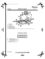
PRODUCT SHEET
CONTROL PANEL
A.
Light ON/OFF switch.
B.
ON/OFF and speed 1 selector switch
(small amount of steam and fumes).
C.
Speed 2 selector switch
(medium amount of steam and fumes).
C+D.
Speed 3 selector switch
(large amount of steam and fumes).
1. Control panel.
2. Grease filter.
3. Grease filter handle.
4. Halogen bulbs.
5. Steam deflector screen.
6. Steam deflector runners.
7. Air outlet (filter version).
8. Casing (two sizes provided).
9. Fixing points to wall unit.
10. Door for inspecting the extraction unit (ACCESS RESTRICTED TO QUALIFIED TECHNICIANS ONLY).
PL SK H RUS
CZ
BG RO GB
31833165.fm Page 29 Thursday, April 28, 2005 6:00 PM

5019 318 33165
AKR 638
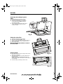
Fitting the carbon filter
1. Disconnect the electrical power supply.
2. Remove the grease filter (f1-f2 - Fig. 8).
3. Insert the carbon filter under the top clips T (Fig. 9.1).
Secure in place with the bottom clips S (Fig. 9.2).
4. Refit the grease filter.
Reverse the above procedure to remove
the carbon filter.
Replacing bulbs
1. Disconnect the electrical power supply. Wait until the
bulbs have cooled down.
2. Use a small screwdriver or any other suitable tool to
prise off the lamp.
Replace it with a PHILIPS STANDARD LINE code
425409 halogen bulb or with a new 12 V 20 W 30° Ø 35
12 V GU4 bulb.
3. Fit the new bulb, proceeding in reverse order.
Fig. 8
Removing and washing the grease
filters
Wash the grease filter at least once a month.
1. Disconnect the electrical power supply.
2. Remove the grease filters - Fig. 8: pull the
spring release handle (f1-f2) downwards,
then remove the filter.
3. After cleaning the grease filter refit in reverse
order, making sure the entire extraction
surface is covered.
Fig. 9.1
Fig. 9.2
T
T
S
S
PL SK H RUS
CZ
BG RO GB
31833165.fm Page 30 Thursday, April 28, 2005 6:00 PM
-
 1
1
-
 2
2
-
 3
3
-
 4
4


Whirlpool AKR 638 IX Program Chart
- Categorie
- Hote pentru aragaz
- Tip
- Program Chart
în alte limbi
- English: Whirlpool AKR 638 IX
- slovenčina: Whirlpool AKR 638 IX
Lucrări înrudite
-
Whirlpool AKR 950 IX WP Program Chart
-
Whirlpool AKR 638 IX Program Chart
-
-
Whirlpool AKR 951 IX WP Program Chart
-
-
-
Whirlpool AKR 957 IX WP Program Chart
-
Whirlpool AKR 420 AV-1 Manualul utilizatorului
-
-
Whirlpool AKR 995 IX Program Chart