Hach Flow Cell FC 48/10 USC Ghid de inițiere rapidă
- Tip
- Ghid de inițiere rapidă

DOC273.98.90651
Flow Cell FC 48/10 USC
09/2018, Edition 1
Quick start guide
Kurzanleitung
Guida rapida all'uso
Guide de démarrage rapide
Guía de inicio rápido
Hurtigstartguide
Beknopte handleiding
Skrócona instrukcja obsługi
Rövid útmutató
Ghid de iniţiere rapidă

1
Table of Contents
1 English FlowCell FC 48/10 USC ............................................................... 3
2 Deutsch FlowCell FC 48/10 USC ........................................................... 13
3 Italiano FlowCell FC 48/10 USC ............................................................. 23
4 Français FlowCell FC 48/10 USC .......................................................... 33
5 Español FlowCell FC 48/10 USC ........................................................... 43
6 Dansk FlowCell FC 48/10 USC ............................................................... 53
7 Nederlands FlowCell FC 48/10 USC ..................................................... 63
8 Polski FlowCell FC 48/10 USC ................................................................ 73
9 Magyar FlowCell FC 48/10 USC ............................................................. 83
10 Română FlowCell FC 48/10 USC ........................................................ 93

Table of Contents
2

3
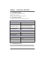
1 English FlowCell FC 48/10 USC
1.1 Legal information
Manufacturer: TriOS Mess- und Datentechnik GmbH
Distributor: Hach Lange GmbH
The translation of the manual is approved by the manufacturer.
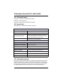
1.2 Specifications
Specifications are subject to change without notice.
1.3 General information
In no event will the manufacturer be liable for direct, indirect, special, incidental or
consequential damages resulting from any defect or omission in this manual. The
manufacturer reserves the right to make changes in this manual and the products it
describes at any time, without notice or obligation. Revised editions are found on
the manufacturer’s website.
ENERGY SUPPLY
Voltage supply
12–24 V DC (± 10%)
Power consumption
≤ 15 W
Control connection
Trigger input to initiate ultrasonic cleaning (galvanically
isolated); Control voltage 5–24 V DC; Connection via
M5-connector (a suitable M5 connection cable with open end
is included in the delivery)
Power cable
M5-connector with optional DC power adapter cable and
suitable 230 V power supply
AMBIENT
Operating temperature
1 to 40 °C (33.8 to 104 °F)
Storage temperature
–20 to 70 °C (–4 to 158 °F)
Protection type
IP 64
MECHANICS
Dimensions (W/H/D)
115 x 136 x 90 mm (4.53 x 5.35 x 3.54 in.)
Weight
1 kg (2.20 lb)
Materials
Polyoxymethylene (POM) housing
Certification
CE compliant

FlowCell FC 48/10 USC
4 English
1.3.1 Safety information
Please read this entire manual before unpacking, setting up, or operating this
equipment. Pay attention to all danger and caution statements. Failure to do so
could result in serious injury to the operator or damage to the equipment.
Make sure that the protection provided by this equipment is not impaired, do not
use or install this equipment in any manner other than that specified in this manual.
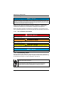
1.3.2 Use of hazard information
1.3.3 Precautionary labels
Read all labels and tags attached to the instrument. Personal injury or damage to
the instrument could occur if not observed. A symbol, if noted on the instrument, will
be included with a danger or caution statement in the manual.
NOTICE
The manufacturer is not responsible for any damages due to misapplication or misuse of
this product including, without limitation, direct, incidental and consequential damages, and
disclaims such damages to the full extent permitted under applicable law. The user is solely
responsible to identify critical application risks and install appropriate mechanisms to protect
processes during a possible equipment malfunction.
DANGER
Indicates a potentially or imminently hazardous situation which, if not avoided, will result in
death or serious injury.
WARNING
Indicates a potentially or imminently hazardous situation which, if not avoided, could result in
death or serious injury.
CAUTION
Indicates a potentially hazardous situation which, if not avoided, could result in minor or
moderate injury.
NOTICE
Indicates a situation that is not related to personal injury.
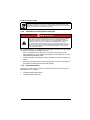
This symbol, if noted on the instrument, references the instruction manual for
operation and/or safety information.
Electrical equipment marked with this symbol may not be disposed of in
European domestic or public disposal systems. Return old or end-of-life
equipment to the manufacturer for disposal at no charge to the user.

FlowCell FC 48/10 USC
English 5
1.3.4 Chemical and Biological Safety
Normal operation of this device may require the use of chemicals or samples that
are biologically unsafe.
• Observe all cautionary information printed on the original solution containers
and safety data sheets prior to their use.
• Dispose of all consumed solutions in accordance with the local and national
regulations and laws.
• Select the type of protective equipment suitable to the concentration and
quantity of the dangerous material being used.
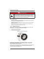
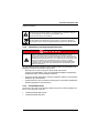
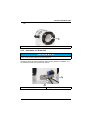
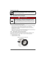
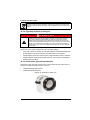
1.3.5 Product overview
The FlowCell FC 48/10 USC is suitable for NX7500 optical sensors with a path
length of up to 10 mm. There are two versions available:
• LXZ529.99.0002A without panel
• LXZ529.99.0003A with panel
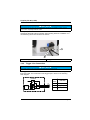
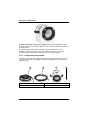
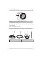
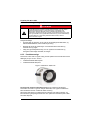
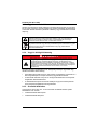
Figure 1 FlowCell FC 48/10 USC
FlowCell with integrated ultra sonic cleaning: In addition to the standard
FlowCell, Hach now also offers an ultrasonic FlowCell which combines the
bypass-installation with direct cleaning.
Fouling on the measurement windows can be prevented by the use of ultrasound.
The condition of the optical path can be monitored at any time through the
monitoring window and the lighting unit.
DANGER
Chemical or biological hazards. If this instrument is used to monitor a
treatment process and/or chemical feed system for which there are regulatory
limits and monitoring requirements related to public health, public safety, food
or beverage manufacture or processing, it is the responsibility of the user of
this instrument to know and abide by any applicable regulation and to have
sufficient and appropriate mechanisms in place for compliance with applicable
regulations in the event of malfunction of the instrument.

FlowCell FC 48/10 USC
6 English
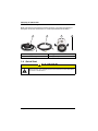
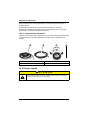
1.3.6 Product components
Make sure that all components have been received. If any items are missing or
damaged, contact the manufacturer or a sales representative immediately.
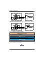
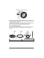
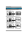
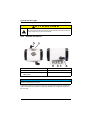
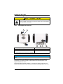
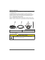
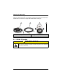
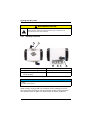
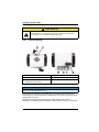
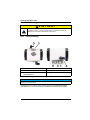
1.4 Quick Start
1 Power supply 2 Trigger line
3 FlowCell incl. fittings 4 Alignment pin
CAUTION
Multiple hazards. Only qualified personnel must conduct the tasks described in
this section of the document.
3
4
21

FlowCell FC 48/10 USC
English 7
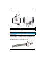
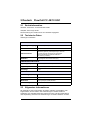
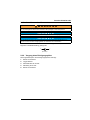
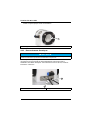
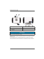
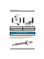
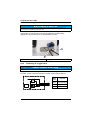
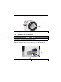
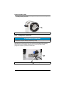
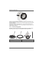
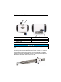
1.4.1 FlowCell design
The Ultrasonic FlowCell is used for cleaning of the measurement windows with
severe dirt contamination. It is suitable for photometers with a path length of up to
10 mm.
The FlowCell provides a light source on the inside which can be activated by
pressing the light button on the side of the housing. When cleaning is in process a
blue LED is used, if cleaning is inactive the light will be white.
1 Outlet for 6 mm hose 2 Monitoring window
3 Inlet for 8 mm hose 4 Power supply
5 Trigger connection to initiate
cleaning
6 Light button
NOTICE
Before setting to work, the FlowCell has to be mounted correctly on the sensor and be filled
with water completely.
3
1 2
4
5
6

FlowCell FC 48/10 USC
8 English
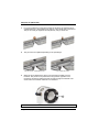
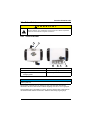
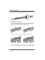
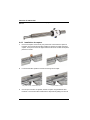
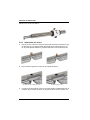
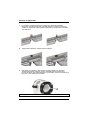
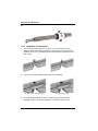
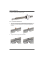
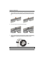
1.4.2 Installation of the sensor
1. For correct positioning of the sensor inside the FlowCell, an alignment pin is
supplied that has to be installed at the bottom of the optical path of the sensor.
The pin can easily be tightened and adjusted by using a small coin.
2. The pin has to be adjusted depending on the path length.
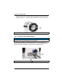
3. When the pin is adjusted, the sensor can be inserted carefully into the
FlowCell. The pin has to be positioned in the guidance opposite to the
monitoring window and will then be led correctly through the FlowCell. The
sensor has to be inserted until there is a resistance.
90° for 10 mm, 2 mm and 0,3 mm 0° for 5 mm and 1 mm
1 Guidance
1

FlowCell FC 48/10 USC
English 9
1.4.3 Connection of electronics
It is a prerequisite that the sensor and FlowCell are installed and mounted correctly
and that the FlowCell is filled completely before starting electronic installation. For
commissioning follow the instructions as follows:
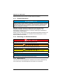
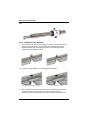
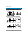
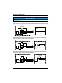
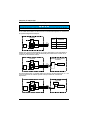
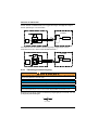
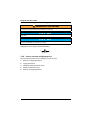
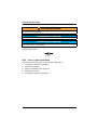
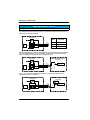
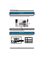
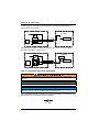
1.4.4 Trigger Line Connection
The trigger line has three connections that leads out of the FlowCell through a
three-wire cable. The construction of the trigger input is shown in the following
block diagram.
NOTICE
FlowCell electronics can only be installed after the sensor is installed correctly and the
Flow-Cell is completely filled with water.
1 Power supply 2 Trigger line
NOTICE
The trigger signal must be applied for at least 100 ms (debouncing)!
1
2
FlowCell
μC
DC
DC
blue
white
brown
Wire
color
Function
blue
white
brown
+5 V (isolated)
Trigger input
GND (isolated)

FlowCell FC 48/10 USC
10 English
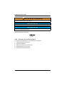
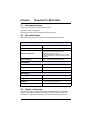
To trigger a cleaning process there are two options: You can use the 5 V signal that
is led out of the FlowCell to realize a triggering over an external switch contact.
Alternatively an external signal voltage of 5 to 24 V DC (in reference to GND-line)
can be put on the “Trigger input” line.
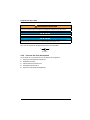
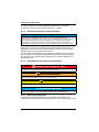
1.4.5 Connection of power supply
The power supply is connected through the power socket of the FlowCell like it is
shown in the following polarity illustration.
WARNING
Electrical shock and fire hazards. Make sure that the supplied cord and non-locking plug
meet the applicable country code requirements.
NOTICE
The manufacturer recommends to use only the supplied power supply.
NOTICE
For the power supply of the FlowCell electronics, a power supply unit of 12 to 24 V DC with
an output cable with at least 15 W is needed.
FlowCell
External measurement
controller
Cleaning cycle
Trigger
μC
DC
DC
blue
white
brown
FlowCell
External measurement
controller
Cleaning cycle
Trigger
+5..24 VDC
GND
μC
DC
DC
blue
white
brown
2,1 x 5,5
–
+

FlowCell FC 48/10 USC
English 11
1.4.6 Process of a cleaning cycle
The program sequence of a cleaning cycle is as follows:
1. Wait for trigger event
2. Trigger activated
3. Ultrasound active for 30 sec.
4. Cool-down for 60 sec.
5. Wait for trigger event

FlowCell FC 48/10 USC
12 English

13
2 Deutsch FlowCell FC 48/10 USC
2.1 Rechtsinformation
Hersteller: TriOS Mess- und Datentechnik GmbH
Vertreiber: Hach Lange GmbH
Die Übersetzung des Handbuchs ist vom Hersteller freigegeben.
2.2 Technische Daten
Änderungen vorbehalten.
2.3 Allgemeine Informationen
Der Hersteller ist nicht verantwortlich für direkte, indirekte, versehentliche oder
Folgeschäden, die aus Fehlern oder Unterlassungen in diesem Handbuch
entstanden. Der Hersteller behält sich jederzeit und ohne vorherige Ankündigung
oder Verpflichtung das Recht auf Verbesserungen an diesem Handbuch und den
ENERGIEVERSORGUNG
Spannungsversorgung
12–24 V DC (± 10%)
Stromverbrauch
≤ 15 W
Steueranschluss
Triggereingang zum Start der Ultraschallreinigung
(galvanisch getrennt), Steuerspannung 5–24 V DC
Anschluss über M5-Anschluss (ein geeignetes
M5-Anschlusskabel mit offenem Ende ist in
der Lieferung enthalten)
Netzkabel
M5-Anschluss mit optionalem Gleichstrom-Netzadapterkabel
und geeigneter 230 V-Stromversorgung
UMGEBUNGSTEMPERATUR
Operating temperature
1 bis 40 °C (33.8 bis 104 °F)
Lagertemperatur
–20 bis 70 °C (–4 bis 158 °F)
Schutztyp
IP 64
MECHANIK
Abmessungen (B/H/T)
115 x 136 x 90 mm (4.53 x 5.35 x 3.54 in.)
Gewicht
1 kg (2.20 lb)
Materialien
Polyoxymethylen (POM) Gehäuse
Zertifizierungen
CE-konform

FlowCell FC 48/10 USC
14
hierin beschriebenen Produkten vor. Überarbeitete Ausgaben der
Bedienungsanleitung sind auf der Hersteller-Webseite erhältlich.
2.3.1 Sicherheitshinweise
Bitte lesen Sie dieses Handbuch komplett durch, bevor Sie dieses Gerät
auspacken, aufstellen oder bedienen. Beachten Sie alle Gefahren- und
Warnhinweise. Nichtbeachtung kann zu schweren Verletzungen des Bedieners
oder Schäden am Gerät führen.
Stellen Sie sicher, dass die durch dieses Messgerät bereitgestellte Sicherheit nicht
beeinträchtigt wird. Verwenden bzw. installieren Sie das Messsystem nur wie in
diesem Handbuch beschrieben.
2.3.2 Bedeutung von Gefahrenhinweisen
2.3.3 Warnhinweise
Lesen Sie alle am Gerät angebrachten Aufkleber und Hinweise. Nichtbeachtung
kann Verletzungen oder Beschädigungen des Geräts zur Folge haben.
H I N W E I S
Der Hersteller ist nicht für Schäden verantwortlich, die durch Fehlanwendung oder
Missbrauch dieses Produkts entstehen, einschließlich, aber ohne Beschränkung auf direkte,
zufällige oder Folgeschäden, und lehnt jegliche Haftung im gesetzlich zulässigen Umfang
ab. Der Benutzer ist selbst dafür verantwortlich, schwerwiegende Anwendungsrisiken zu
erkennen und erforderliche Maßnahmen durchzuführen, um die Prozesse im Fall von
möglichen Gerätefehlern zu schützen.
G E F A H R
Kennzeichnet eine mögliche oder drohende Gefahrensituation, die, wenn sie nicht
vermieden wird, zum Tod oder zu schweren Verletzungen führt.
W A R N U N G
Kennzeichnet eine mögliche oder drohende Gefahrensituation, die, wenn sie nicht
vermieden wird, zum Tod oder zu schweren Verletzungen führen kann.
V O R S I C H T
Kennzeichnet eine mögliche Gefahrensituation, die zu geringeren oder moderaten
Verletzungen führen kann.
H I N W E I S
Kennzeichnet eine Situation, die, wenn sie nicht vermieden wird, das Gerät beschädigen
kann. Informationen, die besonders beachtet werden müssen.

FlowCell FC 48/10 USC
15
Im Handbuch wird in Form von Warnhinweisen auf die am Gerät angebrachten
Symbole verwiesen.
2.3.4 Chemische und biologische Sicherheit
Der Normalbetrieb dieses Gerätes erfordert möglicherweise die Verwendung von
biologisch unsicheren Chemikalien oder Proben.
• Beachten Sie vor dem Umgang mit diesen Stoffen alle auf den
Original-Lösungsbehältern und in den Sicherheitsdatenblättern abgedruckten
Gefahrenhinweise und Sicherheitsinformationen.
• Entsorgen Sie alle gebrauchten Lösungen gemäß den örtlichen und nationalen
Bestimmungen und Gesetzen.
• Wählen Sie die für die Konzentration und Menge des verwendeten gefährlichen
Materials geeignete Schutzausrüstung..
2.3.5 Produktübersicht
FlowCell FC 48/10 USC ist für NX7500 optische Sensoren mit einer Weglänge von
bis zu 10 mm geeignet. Versionen:
• LXZ529.99.0002A without panel
• LXZ529.99.0003A with panel
Dies ist das Sicherheits-Warnsymbol. Befolgen Sie alle Sicherheitshinweise im
Zusammenhang mit diesem Symbol, um Verletzungen zu vermeiden. Wenn es
am Gerät angebracht ist, beachten Sie die Betriebs- oder
Sicherheitsinformationen im Handbuch.
Elektrogeräte, die mit diesem Symbol gekennzeichnet sind, dürfen nicht im
normalen öffentlichen Abfallsystem entsorgt werden. Senden Sie Altgeräte an
den Hersteller zurück. Dieser entsorgt die Geräte ohne Kosten für den Benutzer.
G E F A H R
Chemische und biologische Risiken. Wird das Gerät dazu verwendet, ein
Verfahren und/oder eine chemische Zuleitung zu überwachen, für das
vorgeschriebene Grenzwerte und Überwachungsvorschriften im Bereich der
öffentlichen Sicherheit, der Gesundheit oder im Bereich der Lebensmittel- oder
Getränkeherstellung bestimmt wurden, so unterliegt es der Verantwortung des
Benutzers des Geräts, alle solche Bestimmungen zu kennen und diese
einzuhalten und für ausreichende und entsprechende Vorsorgemaßnahmen
zur Einhaltung der für den Fall einer Fehlfunktion des Geräts bestehenden
Bestimmung zu sorgen.

16
Abbildung 2 FlowCell FC 48/10 USC
FlowCell mit integrierter Ultraschallreinigung: Zusätzlich zur Standard-FlowCell
bietet Hach jetzt auch eine Ultraschall-FlowCell an, die die Bypass-Installation mit
einer direktenReinigung kombiniert.
Verschmutzungen auf den Messfenstern können durch den Einsatz von Ultraschall
verhindert werden. Der Zustand des Lichtwegs kann jederzeit durch das
Überwachungsfenster und die Beleuchtungseinheit überwacht werden.
2.3.6 Produktkomponenten
Stellen Sie sicher, dass Sie alle Teile erhalten haben. Wenn Komponenten fehlen
oder beschädigt sind, kontaktieren Sie bitte umgehend den Hersteller oder
Verkäufer.
1 Stromversorgung 2 Triggerleitung
3 FlowCell inkl. Armatur 4 Ausrichtungsstift
3
4
21

FlowCell FC 48/10 USC
17
2.4 Schnellstart
2.4.1 FlowCell Aufbau
Die Ultrasonic FlowCell wird zur Reinigung stark verschmutzter Messfenster
verwendet. Sie ist für Photometer mit einer Weglänge von bis zu 10 mm geeignet.
FlowCell bietet eine Lichtquelle im Inneren, die durch Drücken des Lichtknopfs an
der Gehäuseseite aktiviert werden kann. Während des Reinigungsvorgangs
V O R S I C H T
Mehrere Gefahren. Nur qualifiziertes Personal sollte die in diesem Kapitel des
Dokuments beschriebenen Aufgaben durchführen.
1 Auslass für 6 mm Schlauch 2 Überwachungsfenster
3 Einlass für 8 mm Schlauch 4 Stromversorgung
5 Trigger-Anschluss zum
Reinigungsstart
6 Lichtknopf
H I N W E I S
Vor der Inbetriebnahme muss FlowCell korrekt auf dem Sensor montiert und vollständig mit
Wasser gefüllt sein.
3
1 2
4
5
6

FlowCell FC 48/10 USC
18
leuchtet eine blaue LED; wenn die Reinigung ausgeschaltet ist, ist die Leuchte
weiß.
2.4.2 Installation des Sensors
1. Zur korrekten Positionierung des Sensors im Inneren der FlowCell wird ein
Ausrichtungsstift eingesetzt, der am Boden des Lichtwegs des Sensors
installiert werden muss. Der Stift kann einfach mit einer kleinen Münze
festgezogen und eingestellt werden.
2. Der Stift ist in Abhängigkeit von der Weglänge einzustellen.
3. Wenn der Stift eingestellt wird, kann der Sensor vorsichtig in die FlowCell
eingesetzt werden. Der Stift muss in der Führung gegenüber dem
Überwachungsfenster positioniert werden und wird dann korrekt durch die
90° für 10 mm, 2 mm und 0,3 mm 0° für 5 mm und 1 mm

FlowCell FC 48/10 USC
19
FlowCell geführt. Der Sensor muss eingesetzt werden, bis er auf Widerstand
trifft.
2.4.3 Anschluss von Elektronik
It is a prerequisite that the sensor and FlowCell are installed and mounted correctly
and that the FlowCell is filled completely before starting electronic installation. For
commissioning follow the instructions as follows:
1 Führung
H I N W E I S
FlowCell-Elektronik kann erst installiert werden, nachdem der Sensor korrekt installiert
wurde und die FlowCell vollständig mit Wasser gefüllt ist.
1 Stromversorgung 2 Triggerleitung
1
1
2
Pagina se încarcă ...
Pagina se încarcă ...
Pagina se încarcă ...
Pagina se încarcă ...
Pagina se încarcă ...
Pagina se încarcă ...
Pagina se încarcă ...
Pagina se încarcă ...
Pagina se încarcă ...
Pagina se încarcă ...
Pagina se încarcă ...
Pagina se încarcă ...
Pagina se încarcă ...
Pagina se încarcă ...
Pagina se încarcă ...
Pagina se încarcă ...
Pagina se încarcă ...
Pagina se încarcă ...
Pagina se încarcă ...
Pagina se încarcă ...
Pagina se încarcă ...
Pagina se încarcă ...
Pagina se încarcă ...
Pagina se încarcă ...
Pagina se încarcă ...
Pagina se încarcă ...
Pagina se încarcă ...
Pagina se încarcă ...
Pagina se încarcă ...
Pagina se încarcă ...
Pagina se încarcă ...
Pagina se încarcă ...
Pagina se încarcă ...
Pagina se încarcă ...
Pagina se încarcă ...
Pagina se încarcă ...
Pagina se încarcă ...
Pagina se încarcă ...
Pagina se încarcă ...
Pagina se încarcă ...
Pagina se încarcă ...
Pagina se încarcă ...
Pagina se încarcă ...
Pagina se încarcă ...
Pagina se încarcă ...
Pagina se încarcă ...
Pagina se încarcă ...
Pagina se încarcă ...
Pagina se încarcă ...
Pagina se încarcă ...
Pagina se încarcă ...
Pagina se încarcă ...
Pagina se încarcă ...
Pagina se încarcă ...
Pagina se încarcă ...
Pagina se încarcă ...
Pagina se încarcă ...
Pagina se încarcă ...
Pagina se încarcă ...
Pagina se încarcă ...
Pagina se încarcă ...
Pagina se încarcă ...
Pagina se încarcă ...
Pagina se încarcă ...
Pagina se încarcă ...
Pagina se încarcă ...
Pagina se încarcă ...
Pagina se încarcă ...
Pagina se încarcă ...
Pagina se încarcă ...
Pagina se încarcă ...
Pagina se încarcă ...
Pagina se încarcă ...
Pagina se încarcă ...
Pagina se încarcă ...
Pagina se încarcă ...
Pagina se încarcă ...
Pagina se încarcă ...
Pagina se încarcă ...
Pagina se încarcă ...
Pagina se încarcă ...
Pagina se încarcă ...
Pagina se încarcă ...
Pagina se încarcă ...
-
 1
1
-
 2
2
-
 3
3
-
 4
4
-
 5
5
-
 6
6
-
 7
7
-
 8
8
-
 9
9
-
 10
10
-
 11
11
-
 12
12
-
 13
13
-
 14
14
-
 15
15
-
 16
16
-
 17
17
-
 18
18
-
 19
19
-
 20
20
-
 21
21
-
 22
22
-
 23
23
-
 24
24
-
 25
25
-
 26
26
-
 27
27
-
 28
28
-
 29
29
-
 30
30
-
 31
31
-
 32
32
-
 33
33
-
 34
34
-
 35
35
-
 36
36
-
 37
37
-
 38
38
-
 39
39
-
 40
40
-
 41
41
-
 42
42
-
 43
43
-
 44
44
-
 45
45
-
 46
46
-
 47
47
-
 48
48
-
 49
49
-
 50
50
-
 51
51
-
 52
52
-
 53
53
-
 54
54
-
 55
55
-
 56
56
-
 57
57
-
 58
58
-
 59
59
-
 60
60
-
 61
61
-
 62
62
-
 63
63
-
 64
64
-
 65
65
-
 66
66
-
 67
67
-
 68
68
-
 69
69
-
 70
70
-
 71
71
-
 72
72
-
 73
73
-
 74
74
-
 75
75
-
 76
76
-
 77
77
-
 78
78
-
 79
79
-
 80
80
-
 81
81
-
 82
82
-
 83
83
-
 84
84
-
 85
85
-
 86
86
-
 87
87
-
 88
88
-
 89
89
-
 90
90
-
 91
91
-
 92
92
-
 93
93
-
 94
94
-
 95
95
-
 96
96
-
 97
97
-
 98
98
-
 99
99
-
 100
100
-
 101
101
-
 102
102
-
 103
103
-
 104
104


Hach Flow Cell FC 48/10 USC Ghid de inițiere rapidă
- Tip
- Ghid de inițiere rapidă
în alte limbi
- français: Hach Flow Cell FC 48/10 USC Guide de démarrage rapide
- English: Hach Flow Cell FC 48/10 USC Quick start guide
- polski: Hach Flow Cell FC 48/10 USC Skrócona instrukcja obsługi
- Deutsch: Hach Flow Cell FC 48/10 USC Schnellstartanleitung
- italiano: Hach Flow Cell FC 48/10 USC Guida Rapida
- español: Hach Flow Cell FC 48/10 USC Guía de inicio rápido
- dansk: Hach Flow Cell FC 48/10 USC Hurtig start guide
- Nederlands: Hach Flow Cell FC 48/10 USC Snelstartgids