Asus B250 MINING EXPERT Manual de utilizare
- Categorie
- Plăci de bază
- Tip
- Manual de utilizare

Motherboard
B250 MINING EXPERT

ii
E13594
Second Edition
October 2017
Copyright © 2017 ASUSTeK COMPUTER INC. All Rights Reserved.
No part of this manual, including the products and software described in it, may be reproduced,
transmitted, transcribed, stored in a retrieval system, or translated into any language in any form or by any
means, except documentation kept by the purchaser for backup purposes, without the express written
permission of ASUSTeK COMPUTER INC. (“ASUS”).
Product warranty or service will not be extended if: (1) the product is repaired, modied or altered, unless
such repair, modication of alteration is authorized in writing by ASUS; or (2) the serial number of the
product is defaced or missing.
ASUS PROVIDES THIS MANUAL “AS IS” WITHOUT WARRANTY OF ANY KIND, EITHER EXPRESS
OR IMPLIED, INCLUDING BUT NOT LIMITED TO THE IMPLIED WARRANTIES OR CONDITIONS OF
MERCHANTABILITY OR FITNESS FOR A PARTICULAR PURPOSE. IN NO EVENT SHALL ASUS, ITS
DIRECTORS, OFFICERS, EMPLOYEES OR AGENTS BE LIABLE FOR ANY INDIRECT, SPECIAL,
INCIDENTAL, OR CONSEQUENTIAL DAMAGES (INCLUDING DAMAGES FOR LOSS OF PROFITS,
LOSS OF BUSINESS, LOSS OF USE OR DATA, INTERRUPTION OF BUSINESS AND THE LIKE),
EVEN IF ASUS HAS BEEN ADVISED OF THE POSSIBILITY OF SUCH DAMAGES ARISING FROM ANY
DEFECT OR ERROR IN THIS MANUAL OR PRODUCT.
SPECIFICATIONS AND INFORMATION CONTAINED IN THIS MANUAL ARE FURNISHED FOR
INFORMATIONAL USE ONLY, AND ARE SUBJECT TO CHANGE AT ANY TIME WITHOUT NOTICE,
AND SHOULD NOT BE CONSTRUED AS A COMMITMENT BY ASUS. ASUS ASSUMES NO
RESPONSIBILITY OR LIABILITY FOR ANY ERRORS OR INACCURACIES THAT MAY APPEAR IN THIS
MANUAL, INCLUDING THE PRODUCTS AND SOFTWARE DESCRIBED IN IT.
Products and corporate names appearing in this manual may or may not be registered trademarks or
copyrights of their respective companies, and are used only for identication or explanation and to the
owners’ benet, without intent to infringe.
Offer to Provide Source Code of Certain Software
This product contains copyrighted software that is licensed under the General Public License (“GPL”),
under the Lesser General Public License Version (“LGPL”) and/or other Free Open Source Software
Licenses. Such software in this product is distributed without any warranty to the extent permitted by the
applicable law. Copies of these licenses are included in this product.
Where the applicable license entitles you to the source code of such software and/or other additional data,
you may obtain it for a period of three years after our last shipment of the product, either
(1) for free by downloading it from http://support.asus.com/download
or
(2) for the cost of reproduction and shipment, which is dependent on the preferred carrier and the location
where you want to have it shipped to, by sending a request to:
ASUSTeK Computer Inc.
Legal Compliance Dept.
15 Li Te Rd.,
Beitou, Taipei 112
Taiwan
In your request please provide the name, model number and version, as stated in the About Box of the
product for which you wish to obtain the corresponding source code and your contact details so that we
can coordinate the terms and cost of shipment with you.
The source code will be distributed WITHOUT ANY WARRANTY and licensed under the same license as
the corresponding binary/object code.
This offer is valid to anyone in receipt of this information.
ASUSTeK is eager to duly provide complete source code as required under various Free Open Source
Software licenses. If however you encounter any problems in obtaining the full corresponding source
code we would be much obliged if you give us a notication to the email address [email protected], stating
the product and describing the problem (please DO NOT send large attachments such as source code
archives, etc. to this email address).

iii
Contents
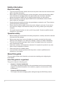
Safety information ...................................................................................... iv
About this guide ......................................................................................... iv
Package contents ....................................................................................... vi
B250 MINING EXPERT specications summary ...................................... vi
Chapter 1: Product introduction
Motherboard overview ............................................................................. 1-1
Central Processing Unit (CPU) ................................................................ 1-6
System memory ........................................................................................ 1-7
Expansion slots ........................................................................................ 1-8
Chapter 2: BIOS information
BIOS setup program ................................................................................. 2-1
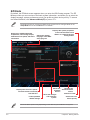
EZ Mode ..................................................................................................... 2-2
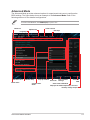
Advanced Mode ........................................................................................ 2-3
Exit menu ................................................................................................... 2-4
Appendix
Notices .......................................................................................................A-1
ASUS contact information .......................................................................A-4

iv
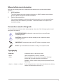
Safety information
Electrical safety
• To prevent electrical shock hazard, disconnect the power cable from the electrical outlet
before relocating the system.
• When adding or removing devices to or from the system, ensure that the power cables
for the devices are unplugged before the signal cables are connected. If possible,
disconnect all power cables from the existing system before you add a device.
• Before connecting or removing signal cables from the motherboard, ensure that all
power cables are unplugged.
• Seek professional assistance before using an adapter or extension cord. These devices
could interrupt the grounding circuit.
• Ensure that your power supply is set to the correct voltage in your area. If you are not
sure about the voltage of the electrical outlet you are using, contact your local power
company.
• If the power supply is broken, do not try to x it by yourself. Contact a qualied service
technician or your retailer.
Operation safety
• Before installing the motherboard and adding components, carefully read all the manuals
that came with the package.
• Before using the product, ensure all cables are correctly connected and the power
cables are not damaged. If you detect any damage, contact your dealer immediately.
• To avoid short circuits, keep paper clips, screws, and staples away from connectors,
slots, sockets and circuitry.
• Avoid dust, humidity, and temperature extremes. Do not place the product in any area
where it may be exposed to moisture.
• Place the product on a stable surface.
• If you encounter technical problems with the product, contact a qualied service
technician or your retailer.
About this guide
This user guide contains the information you need when installing and conguring the
motherboard.
How this guide is organized
This guide contains the following parts:
• Chapter 1: Product introduction
This chapter describes the features of the motherboard and the new technology it
supports. It includes descriptions of the switches, jumpers, and connectors on the
motherboard.
• Chapter 2: BIOS information
This chapter discusses changing system settings through the BIOS Setup menus.

v
Where to nd more information
Refer to the following sources for additional information and for product and software
updates.
1. ASUS websites
The ASUS website provides updated information on ASUS hardware and software
products. Refer to the ASUS contact information.
2. Optional documentation
Your product package may include optional documentation, such as warranty yers,
that may have been added by your dealer. These documents are not part of the
standard package.
Conventions used in this guide
To ensure that you perform certain tasks properly, take note of the following symbols used
throughout this manual.
DANGER/WARNING: Information to prevent injury to yourself when
completing a task.
CAUTION: Information to prevent damage to the components when
completing a task
IMPORTANT: Instructions that you MUST follow to complete a task.
NOTE: Tips and additional information to help you complete a task.
Typography
Bold text Indicates a menu or an item to select.
Italics
Used to emphasize a word or a phrase.
<Key> Keys enclosed in the less-than and greater-than sign
means that you must press the enclosed key.
Example: <Enter> means that you must press the Enter or
Return key.
<Key1> + <Key2> + <Key3> If you must press two or more keys simultaneously, the key
names are linked with a plus sign (+).

vi
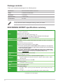
B250 MINING EXPERT specications summary
(continued on the next page)
Package contents
Check your motherboard package for the following items.
Motherboard
ASUS B250 MINING EXPERT motherboard
Cables
2 x Serial ATA 6.0 Gb/s cables
Accessories
1 x I/O Shield
Application DVD 1 x Support DVD
Documentation User Guide
If any of the above items is damaged or missing, contact your retailer.
CPU
LGA1151 socket for Intel
®
7th/6th Generation Core™ i7 / i5 / i3, Pentium
®
, and
Celeron
®
processors
Supports Intel
®
14nm CPU
Supports Intel
®
Turbo Boost Technology 2.0*
* The Intel
®
Turbo Boost Technology 2.0 support depends on the CPU types.
** Refer to www.asus.com for Intel
®
CPU support list.
Chipset Intel
®
B250 Chipset
Memory
2 x DIMMs, maximum 32GB, DDR4 2400*/2133**MHz, non-ECC, un-buffered
memory***
Dual-channel memory architecture
Supports Intel
®
Extreme Memory Prole (XMP)
* Due to Intel
®
chipset limitation, DDR4 2400MHz memory frequency is only supported
by 7th Generation Intel
®
processors. Higher memory modules will run at the maximum
transfer rate of DDR4 2400MHz.
** Due to Intel
®
chipset limitation, DDR4 2133MHz and higher memory modules on 6th
Generation Intel
®
processors will run at the maximum transfer rate of DDR4 2133MHz.
*** Refer to www.asus.com for the Memory QVL(Qualied Vendors List)
Expansion
slots
1 x PCI Express x16 slot (at x16 mode)
18 x PCI Express x1 slots
Graphics
Integrated graphics processor - Intel
®
HD Graphics support
- Supports HDMI with maximum resolution of 4096 x 2160 @ 24Hz / 2560 x
1600 @ 60Hz
Maximum shared memory of 1024 MB
Storage
Intel
®
B250 Chipset:
- 4 x SATA 6.0 Gb/s ports (gray)
LAN Intel
®
I219V Gigabit LAN
USB
Intel
®
B250 Chipset
- 6 x USB 3.1 Gen 1 ports (2 ports at mid-board; 4 ports at back panel, blue,
Type A)
- 4 x USB 2.0/1.1 ports (2 ports at mid-board; 2 ports at back panel)

vii
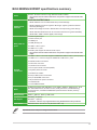
B250 MINING EXPERT specications summary
Audio
Realtek
®
ALC887 8-channel* High Denition Audio CODEC
* Use a chassis with HD audio module in the front panel to support an 8-channel audio
output.
ASUS special
features
ASUS 5X PROTECTION III
- ASUS SafeSlot Core: Fortied PCIe Slot prevents damage
- ASUS LANGuard: Protects against LAN surges, lightning strikes and static-
electricity discharges
- ASUS Overvoltage Protection: World-class circuit-protecting power design
- ASUS Stainless Steel Back I/O: 3X corrosion-resistance for greater durability
- ASUS DIGI+ VRM: 6 Phase digital power design
Rear panel I/O
ports
1 x PS/2 keyboard port
1 x PS/2 mouse port
1 x HDMI port
1 x LAN (RJ-45) port
4 x USB 3.1 Gen 1 ports
2 x USB 2.0/1.1 ports
3 x Audio jacks support 8-channel audio output
* Use a chassis with HD audio module in the front panel to support an 8-channel audio
output.
Internal
connectors
1 x USB 3.1 Gen 1 connector supports additional 2 USB 3.1 Gen 1 ports (19-pin)
1 x USB 2.0/1.1 connector supports additional 2 USB 2.0/1.1 ports
4 x SATA 6.0Gb/s connectors
1 x CPU Fan connector
1 x Chassis Fan connector
1 x Front panel audio connector(AAFP)
1 x System panel connector
1 x S/PDIF out header
3 x 24-pin EATX power connectors
3 x 4-pin AUXPWR connectors
1 x 8-pin EATX 12V power connector
1 x COM header
1 x Clear CMOS header
BIOS
64 Mb Flash ROM, UEFI AMI BIOS, PnP, DMI3.0, WfM2.0, SM BIOS 3.0, ACPI
6.0, ASUS EZ Flash 3, F6 Qfan Control, F3 My Favorites, Last Modied log,
F12 PrintScreen, and ASUS DRAM SPD (Serial Presence Detect) memory
information
Manageability WfM 2.0, DMI 3.0, WOL by PME, PXE
OS Support
Windows
®
10 (64-bit)
Windows
®
7 (64-bit)*
* Windows
®
7 64-bit is only supported when using 6th Generation Intel
®
processors.
Form Factor ATX form factor: 12.0 in x 9.1 in (30.5 cm x 23.1 cm)
Specications are subject to change without notice.

ASUS B250 MINING EXPERT
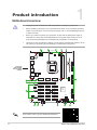
1-1
Product introduction
1
Motherboard overview
• Unplugthepowercordfromthewallsocketbeforetouchinganycomponent.
• Beforehandlingcomponents,useagroundedwriststraportouchasafelygrounded
objectorametalobject,suchasthepowersupplycase,toavoiddamagingthemdue
tostaticelectricity.
• Beforeyouinstallorremoveanycomponent,ensurethattheATXpowersupplyis
switchedofforthepowercordisdetachedfromthepowersupply.Failuretodoso
maycauseseveredamagetothemotherboard,peripherals,orcomponents.
• Unplugthepowercordbeforeinstallingorremovingthemotherboard.Failuretodoso
cancauseyouphysicalinjuryanddamagetomotherboardcomponents.
Place this
side towards
the rear of the
chassis
®
DDR4 DIMM_A1 (64bit, 288-pin module)
DDR4 DIMM_B1 (64bit, 288-pin module)
DIGI+
EPU
ASM
1167
ALC
887
CHA_FAN
CPU_FAN
CLRTC
64Mb
BIOS
SPDIF_OUT
AUXPWR_A3
AUXPWR_A2
AUXPWR_A1
PANEL
AAFP
COM
EATX12V
LGA1151
EATXPWR_AEATXPWR_BEATXPWR_C
Intel
®
B250
Lithium Cell
CMOS Power
U31G1_56
USB78
AUDIO
Super
I/O
A01 A02 A03
A04 A05 A06
B07 B08 B09
B10 B11 B12
C13 C14 C15
C16 C17 C18
PCIEX16_A1
USB910
LAN_U31G1_34
LANGuard
Intel
I219V
HDMI
KBMS
23.1cm(9.1in)
30.5cm(12.0in)
SATA6G_3 SATA6G_4
SATA6G_2 SATA6G_1
U31G1_12
1
6
7101112
1
13
14
1 42 53
9 8
ScantheQRcodetogetthedetailedpindenitions.

1-2
Chapter 1: Product introduction
Intel
®
LGA1151 CPU socket
InstallIntel
®
LGA1151CPUintothissurfacemountLGA1151socket,whichis
designedfor7th/6thGenerationIntel
®
Core™i7/i5/i3,Pentium
®
,andCeleron
®
processors.
Formoredetails,refertoCentral Processing Unit (CPU).
CPU and chassis fan connectors (4-pin CPU_FAN, 4-pin CHA_FAN)
Connectthefancablestothefanconnectorsonthemotherboard,ensuringthatthe
blackwireofeachcablematchesthegroundpinoftheconnector.
Donotforgettoconnectthefancablestothefanconnectors.Insufcientairowinside
thesystemmaydamagethemotherboardcomponents.Thesearenotjumpers!Donot
placejumpercapsonthefanconnectors!TheCPU_FANconnectorsupportsaCPUfan
ofmaximum1A(12W)fanpower.
DDR4 DIMM slots
Install2GB,4GB,8GB,and16GBunbufferednon-ECCDDR4DIMMsintothese
DIMMsockets.
• Tomakeyourbuildmorestable,whenusing8ormoreminingcards,we
recommendthatyouinstall4GBmemorymodulesandchangethesizeofthe
virtualmemorypagingleto20GB.
• Formoredetails,refertoSystem memory.
ATX power connectors (24-pin EATXPWR_A/B/C, 8-pin EATX12V, 4-pin
AUXPWR_A1/A2/A3)
CorrectlyorienttheATXpowersupplyplugsintotheseconnectorsandpushdown
rmlyuntiltheconnectorscompletelyt.
• Inordertofullysupport19graphiccardsmining,werecommendthatyouuse3
powersupplyunits(PSU)thataredesignedforminingwithsufcient12Vpower
plugsandprovideaminimumpowerof3750Wintotal(2*1250W+1*1350Ware
recommended).
• AUXPWR_A1/A2/A3mustbeconnectedtothesamepowersupplypluggedinthe
24-pinEATXPWR_Aconnector.
• WerecommendthatyouuseaPSUwithhigherpoweroutputwhenconguringa
systemwithmorepower-consumingdevicesorwhenyouintendtoinstalladditional
devices.Thesystemmaybecomeunstableormaynotbootupifthepoweris
inadequate.
•
Ifyouareuncertainabouttheminimumpowersupplyrequirementforyoursystem,
refertotheRecommendedPowerSupplyWattageCalculatorathttp://support.
asus.com/PowerSupplyCalculator/PSCalculator.aspx?SLanguage=en-usfor
details.

ASUS B250 MINING EXPERT
1-3
System panel connector (20-5 pin F_PANEL)
Thisconnectorsupportsseveralchassis-mountedfunctions.
Intel
®
B250 Serial ATA 6.0Gb/s connectors (7-pin SATA6G_1~4)
TheseconnectorsconnecttoSerialATA6.0Gb/sharddiskdrivesviaSerialATA
6.0Gb/ssignalcables.
USB 2.0 connector (10-1 pin USB910)
ConnectaUSBmodulecabletothisconnector,theninstallthemoduletoaslot
openingatthebackofthesystemchassis.TheseUSBconnectorscomplywith
USB2.0specicationsandsupportsupto480Mbpsconnectionspeed.
Serial port connector (10-1 pin COM)
Connecttheserialportmodulecabletothisconnector,theninstallthemoduletoa
slotopeningatthebackofthesystemchassis.
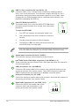
Clear RTC RAM (2-pin CLRTC)
ThisheaderallowsyoutocleartheCMOSRTCRAMdataof
thesystemsetupinformationsuchasdate,time,andsystem
passwords.
To erase the RTC RAM:
1. TurnOFFthecomputerandunplugthepowercord.
2. Useametalobjectsuchasascrewdrivertoshortthe
twopins.
3. PlugthepowercordandturnONthecomputer.
4. Holddownthe<Del>keyduringthebootprocessand
enterBIOSsetuptore-enterdata.
CLRTC
+3V_BAT
GND
PIN 1
Ifthestepsabovedonothelp,removetheonboardbatteryandshortthetwopinsagain
tocleartheCMOSRTCRAMdata.AfterclearingtheCMOS,reinstallthebattery.
Digital audio connector (4-1 pin SPDIF_OUT)
ConnecttheS/PDIFOutmodulecabletothis
connector,theninstallthemoduletoaslot
openingatthebackofthesystemchassis.
SPDIF_OUT
+5V
SPDIFOUT
GND
PIN 1
USB 3.1 Gen 1 connector (20-1 pin U31G1_12)
ConnectaUSB3.1Gen1moduletothisconnectorforadditionalUSB3.1
Gen1frontorrearpanelports.ThisconnectorcomplieswithUSB3.1Gen1
specicationsandprovidefasterdatatransferspeedsofupto5Gbps,faster
chargingtimeforUSB-chargeabledevices,optimizedpowerefciency,and
backwardcompatibilitywithUSB2.0.

1-4
Chapter 1: Product introduction
Front panel audio connector (10-1 pin AAFP)
Thisconnectorisforachassis-mountedfrontpanelaudioI/Omodulethatsupports
eitherHDAudioorlegacyAC`97audiostandard.Connectoneendofthefront
panelaudioI/Omodulecabletothisconnector.
• Werecommendthatyouconnectahigh-denitionfrontpanelaudiomoduletothis
connectortoavailofthemotherboard’shigh-denitionaudiocapability.
• Ifyouwanttoconnectahigh-denitionfrontpanelaudiomoduletothisconnector,
settheFrontPanelTypeitemintheBIOSsetupto[HDAudio].Ifyouwantto
connectanAC’97frontpanelaudiomoduletothisconnector,settheitemto
[AC97].Bydefault,thisconnectorissetto[HDAudio].
PCI Express x16 slot
ThismotherboardsupportsonePCIExpressx16graphiccardsthatcomplywith
thePCIExpressspecications.
PCI Express x1 slots
ThismotherboardhaseighteenPCIExpressx1slotsthatsupportPCIExpress
x1networkcards,SCSIcards,andothercardsthatcomplywiththePCIExpress
specications.
Formoredetails,refertoExpansion slots.
1. PS/2 Mouse port.ThisportconnectstoaPS/2mouse.
2. USB 2.0 ports.These4-pinUniversalSerialBus(USB)portsareforUSB2.0/1.1
devices.
3. HDMI port.ThisportisforaHigh-DenitionMultimediaInterface(HDMI)connector,
andisHDCPcompliantallowingplaybackofHDDVD,Blu-ray,andotherprotected
content.
4. LAN (RJ-45) port.ThisportallowsGigabitconnectiontoaLocalAreaNetwork(LAN)
throughanetworkhub.
5 64
7
3
2
8
1
9
1.2.2 Rear panel connectors

ASUS B250 MINING EXPERT
1-5
5. Line In port (light blue).Thisportconnectstothetape,CD,DVDplayer,orother
audiosources.
6. Line Out port (lime).Thisportconnectstoaheadphoneoraspeaker.Inthe4.1,
5.1and7.1-channelcongurations,thefunctionofthisportbecomesFrontSpeaker
Out.
7. Microphone port (pink).Thisportconnectstoamicrophone.
Refertotheaudiocongurationtableforthefunctionoftheaudioportsin2.1,4.1,5.1,or
7.1-channelconguration.
LAN port
Speed
LED
Activity Link
LED
Activity/Link LED Speed LED
Status Description Status Description
Off Nolink OFF 10Mbpsconnection
Orange Linked ORANGE 100Mbpsconnection
Orange
(Blinking)
Dataactivity GREEN 1Gbpsconnection
Orange
(Blinkingthen
steady)
Readytowake
upfromS5mode
- -
LAN port LED indications
8. USB 3.1 Gen 1 ports (blue, Type A).These9-pinUniversalSerialBus(USB)ports
areforUSB3.1Gen1devices.
• USB3.1Gen1devicescanonlybeusedfordatastorage.
• WestronglyrecommendthatyouconnectUSB3.1Gen1devicestoUSB3.1Gen1
portsforfasterandbetterperformancefromyourUSB3.1Gen1devices.
• DuetothedesignoftheIntel
®
200serieschipset,allUSBdevicesconnectedtothe
USB2.0andUSB3.1Gen1portsarecontrolledbythexHCIcontroller.Somelegacy
USBdevicesmustupdatetheirrmwareforbettercompatibility.
9. PS/2 Keyboard port.ThisportconnectstoaPS/2keyboard.
Audio 2.1, 4.1, 5.1 or 7.1-channel conguration
Port
Headset
2.1-channel
4.1-channel 5.1-channel 7.1-channel
LightBlue(Rearpanel) LineIn RearSpeakerOut RearSpeakerOut RearSpeakerOut
Lime(Rearpanel) LineOut FrontSpeakerOut FrontSpeakerOut FrontSpeakerOut
Pink(Rearpanel) MicIn MicIn Bass/Center Bass/Center
Lime(Frontpanel) - - - SideSpeakerOut
To congure a 7.1-channel audio output:
UseachassiswithHDaudiomoduleinthefrontpaneltosupporta7.1-channelaudio
output.

1-6
Chapter 1: Product introduction
Central Processing Unit (CPU)
ThismotherboardcomeswithasurfacemountLGA1151socket
designedforthe7th/6thGenerationIntel
®
Core™i7/Core™i5/Core™
i3,Pentium
®
andCeleron
®
processors.
UnplugallpowercablesbeforeinstallingtheCPU.
• EnsurethatyouinstallthecorrectCPUdesignedfortheLGA1151socketonly.DO
NOTinstallaCPUdesignedforLGA1150,LGA1155andLGA1156socketsonthe
LGA1151socket.
• Uponpurchaseofthemotherboard,ensurethatthePnPcapisonthesocketand
thesocketcontactsarenotbent.ContactyourretailerimmediatelyifthePnPcap
ismissing,orifyouseeanydamagetothePnPcap/socketcontacts/motherboard
components.
• Keepthecapafterinstallingthemotherboard.ASUSwillprocessReturnMerchandise
Authorization(RMA)requestsonlyifthemotherboardcomeswiththecaponthe
LGA1151socket.
• Theproductwarrantydoesnotcoverdamagetothesocketcontactsresultingfrom
incorrectCPUinstallation/removal,ormisplacement/loss/incorrectremovalofthePnP
cap.
Installing the CPU
1
4
ApplytheThermalInterfaceMaterialtotheCPUheatsinkandCPUbeforeyouinstallthe
heatsinkandfanifnecessary.
2
3
A
B
A
B
C
D
5
4
4
5

ASUS B250 MINING EXPERT
1-7
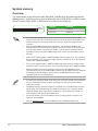
System memory
Overview
ThismotherboardcomeswithtwoDoubleDataRate4(DDR4)DualInlineMemoryModule
(DIMM)sockets.ADDR4moduleisnotcheddifferentlyfromaDDR,DDR2,orDDR3module.
DONOTinstallaDDR,DDR2,orDDR3memorymoduletotheDDR4slot.
• YoumayinstallvaryingmemorysizesinChannelAandChannelB.Thesystem
mapsthetotalsizeofthelower-sizedchannelforthedual-channelconguration.Any
excessmemoryfromthehigher-sizedchannelisthenmappedforsingle-channel
operation.
• AlwaysinstallDIMMswiththesameCASlatency.Foroptimalcompatibility,we
recommendthatyouinstallmemorymodulesofthesameversionordatecode(D/C)
fromthesamevendor.Checkwiththeretailertogetthecorrectmemorymodules.
• AccordingtoIntel
®
CPUspec,DIMMvoltagebelow1.4Visrecommendedtoprotect
theCPU.
• DuetoIntel
®
chipsetlimitation,DDR42400MHzmemoryfrequencyisonlysupported
by7thGenerationIntel
®
processors.Highermemorymoduleswillrunatthemaximum
transferrateofDDR42400MHz.
• DuetoIntel
®
chipsetlimitation,DDR42133MHzandhighermemorymoduleson6th
GenerationIntel
®
processorswillrunatthemaximumtransferrateofDDR42133MHz.
• Memorymoduleswithmemoryfrequencyhigherthan2133/2400MHzandits
correspondingtimingortheloadedX.M.P.ProleisnottheJEDECmemorystandard.
ThestabilityandcompatibilityofthesememorymodulesdependontheCPU’s
capabilitiesandotherinstalleddevices.
• Tomakeyourbuildmorestable,whenusing8ormoreminingcards,werecommend
thatyouinstall4GBmemorymodulesandchangethesizeofthevirtualmemory
pagingleto20GB.
• ThedefaultmemoryoperationfrequencyisdependentonitsSerialPresenceDetect
(SPD),whichisthestandardwayofaccessinginformationfromamemorymodule.
Underthedefaultstate,somememorymodulesforoverclockingmayoperateata
lowerfrequencythanthevendor-markedvalue.
• Forsystemstability,useamoreefcientmemorycoolingsystemtosupportafull
memoryload(2DIMMs).
• Refertowww.asus.comforthelatestMemoryQVL(QualiedVendorsList)
Channel Sockets
ChannelA DIMM_A1
ChannelB DIMM_B1
DIMM_A1
DIMM_B1

1-8
Chapter 1: Product introduction
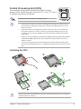
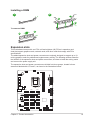
Installing a DIMM
1 2
To remove a DIMM
B
A
B
A
A
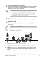
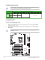
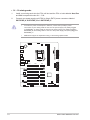
Expansion slots
ThismotherboardcomeswithonePCIex16andeighteen(18)PCIex1expansioncard
slotsthatsupportgraphicscards,networkcards,andothercardsthatcomplywithPCIe
specications.
Theaddedexpansionslotsandpowerconnectorsareuniquelydesignedtosupportupto19
mininggraphicscardsforprofessionalcryptocurrencymining.Thefollowingsectionsdescribe
thelocationoftheexpansionslotsandpowerconnectors,andhowtoinstalltheminingcards
andconnectthepowersupplyunit.
Theexpansionslotsandpowerconnectorsaredividedintothreegroups,locatedinthree
areasandlabeledwithA,BandC,asshownintheillustrationsbelow.
®
AUXPWR_A1
EATXPWR_AEATXPWR_BEATXPWR_C
C13
AUXPWR_A3
C14 C15
C16 C17 C18
A01 A02 A03
A04 A05 A06
PCIEX16_A1
AUXPWR_A2
B07 B08 B09
B10 B11 B12

ASUS B250 MINING EXPERT
1-9
Unplugthepowercordbeforeaddingorremovingexpansioncards.Failuretodosomay
causeyouphysicalinjuryanddamagemotherboardcomponents.
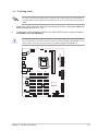
Toinstallminingcards:
• Seven (7) or less mining cards
1. InstallyourminingcardsintothePCIex16slotandthePCIex1slotslabeledAxx in
sequentialorderA01~A06.
2. Connectyourpowersupplyunit(PSU)tothe24-pinEATXpowerconnectorlabeled
EATXPWR_A.
*needAMDdriversupport.
Installing mining cards
AUXPWR_A1/A2/A3mustbeconnectedtothesamepowersupplypluggedinthe24-pin
EATXPWR_Aconnector.
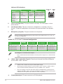
Graphic cards
Quantity of graphic cards for mining
19* 18* 17* 16 15 14 13 12 11 10 9 8 7 6 5 4 3 2 1
NVIDIA
P106 8 7-8
5-8
Nolimit
Regular
cards
N/A N/A
AMD 9-11* 7-8 5-8
®
EATXPWR_A
A01 A02 A03
A04 A05 A06
PCIEX16_A1
AUXPWR_A1
AUXPWR_A3
AUXPWR_A2

1-10
Chapter 1: Product introduction
• 8 ~ 13 mining cards
Tomakeyourbuildmorestable,whenusing8ormoreminingcards,werecommendthat
youinstall4GBmemorymodulesandchangethesizeofthevirtualmemorypagingleto
20GB.
1. InstallyourminingcardsintothePCIex16slotandthePCIex1slotslabeledAxx and
Bxx insequentialorderA01~B12.
2. Connectyourpowersupplyunit(PSU)tothe24-pinEATXpowerconnectorslabeled
EATXPWR_AandEATXPWR_B.
®
EATXPWR_A
EATXPWR_B
EATXPWR_C
A01 A02 A03
A04 A05 A06
PCIEX16_A1
B07 B08 B09
B10 B11 B12
AUXPWR_A1
AUXPWR_A3
AUXPWR_A2
Tomakethepowerconsumptioninbalance,connectthe6-pin/8-pinpowerconnectorsof
yourminingcardsinareaAtothepowersupplyunit(PSU)pluggedinEATXPWR_A,and
miningcardsinareaBtothepowersupplyunit(PSU)pluggedinEATXPWR_B.

ASUS B250 MINING EXPERT
1-11
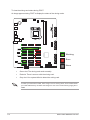
• 14 ~ 19 mining cards
1. InstallyourminingcardsintothePCIex16slotandthePCIex1slotslabeledAxx,Bxx
and Cxx insequentialorderA01~C18.
2. Connectyourpowersupplyunit(PSU)to24-pinEATXpowerconnectorslabeled
EATXPWR_A,EATXPWR_B andEATXPWR_C.
®
AUXPWR_A1
EATXPWR_AEATXPWR_BEATXPWR_C
C13
AUXPWR_A3
C14 C15
C16 C17 C18
A01 A02 A03
A04 A05 A06
PCIEX16_A1
AUXPWR_A2
B07 B08 B09
B10 B11 B12
• Tomakethepowerconsumptioninbalance,connectthe6-pin/8-pinpower
connectorsofyourminingcardsinareaAtothepowersupplyunit(PSU)plugged
inEATXPWR_A,miningcardsinareaBtothepowersupplyunit(PSU)pluggedin
EATXPWR_B,andminingcardsinareaCtothepowersupplyunit(PSU)pluggedin
EATXPWR_C.
• AMDdriversupportisrequiredforusing17andmoregraphicscards.

1-12
Chapter 1: Product introduction
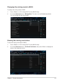
Changing the mining mode in BIOS
TochangetheminingmodeinBIOS:
1. Press<Delete>or<F2>duringPOSTtoenterBIOSSetup.
2. GototheAdvancedmenu>Mining Mode.Thisitemissetto[Enabled]bydefault.
Youcanchangethisitembyyourself.
Viewing the mining card status
ToviewtheminingcardstatusinBIOS:
1. Press<Delete>or<F2>duringPOSTtoenterBIOSSetup.
2. GototheAdvancedmenu>On Board Slot States,thenpress<Enter>todisplaythe
statusoftheexpansioncards.

ASUS B250 MINING EXPERT
1-13
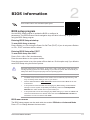
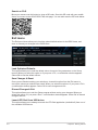
ToviewtheminingcardstatusduringPOST:
AnimageappearsduringPOSTtodisplaythestatusoftheminingcards.
®
Working
Error
None
• Greenslot:Theminingcardworksnormally.
• Redslot:Thereisanerrorwiththeminingcard.
• Grayslot:Yoursystemfailedtodetecttheminingcard.
Tomakeyourbuildmorestable,whenusing8ormoreminingcards,werecommendthat
youinstall4GBmemorymodulesandchangethesizeofthevirtualmemorypagingleto
20GB.
Pagina se încarcă...
Pagina se încarcă...
Pagina se încarcă...
Pagina se încarcă...
Pagina se încarcă...
Pagina se încarcă...
Pagina se încarcă...
Pagina se încarcă...
Pagina se încarcă...
-
 1
1
-
 2
2
-
 3
3
-
 4
4
-
 5
5
-
 6
6
-
 7
7
-
 8
8
-
 9
9
-
 10
10
-
 11
11
-
 12
12
-
 13
13
-
 14
14
-
 15
15
-
 16
16
-
 17
17
-
 18
18
-
 19
19
-
 20
20
-
 21
21
-
 22
22
-
 23
23
-
 24
24
-
 25
25
-
 26
26
-
 27
27
-
 28
28
-
 29
29


Asus B250 MINING EXPERT Manual de utilizare
- Categorie
- Plăci de bază
- Tip
- Manual de utilizare
în alte limbi
- English: Asus B250 MINING EXPERT User manual
- italiano: Asus B250 MINING EXPERT Manuale utente
Lucrări înrudite
-
Asus HYPER M.2 X16 CARD V2 Manual de utilizare
-
Asus H170I-PRO Manual de utilizare
-
Asus EX-B85M-V Manual de utilizare
-
-
-
-
Asus PRIME B450M-A/CSM Manual de utilizare
-
Asus CM6870 EE7010 Manual de utilizare
-
-