Makita GA4040C Manual de utilizare
- Categorie
- Unelte electrice
- Tip
- Manual de utilizare

1
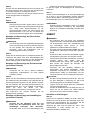
GB Angle Grinder INSTRUCTION MANUAL
UA Кутова шліфувальна машина ІНСТРУКЦІЯ З ЕКСПЛУАТАЦІЇ
PL Szlifierka kątowa INSTRUKCJA OBSŁUGI
RO Polizor unghiular MANUAL DE INSTRUCŢIUNI
DE Winkelschleifer BEDIENUNGSANLEITUNG
HU Sarokcsiszoló HASZNÁLATI KÉZIKÖNYV
SK Uhlová brúska NÁVOD NA OBSLUHU
CZ Úhlová bruska NÁVOD K OBSLUZE
GA4040C
GA4540C
GA5040C
GA6040C
GA4041C
GA4541C
GA5041C

2
1
1 012725
1
2 012728
1
3 012729
1
4 012747 5 012724
1
23
6 012733
1
2
3
4
7 009430
12
8 009431
1
2
3
9 012802
1
2
10 012727
1
2
4
3
11 012772
1
12 012773

3
12
13 010846 14 010863
1
2
3
4
15 012740
1
2
3
16 012742
12
34
17 012731
A
B
18 012730
1
2
3
4
19 010855
1
20 012743
1
21 012744
1
2
22 012732

4
ENGLISH (Original instructions)
Explanation of general view
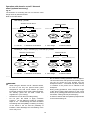
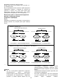
1-1. Shaft lock
2-1. Slide switch
3-1. Indication lamp (speed adjusting
dial)
4-1. Speed adjusting dial
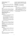
6-1. Wheel guard
6-2. Bearing box
6-3. Screw
7-1. Wheel guard
7-2. Bearing box
7-3. Screw
7-4. Lever
8-1. Screw
8-2. Lever
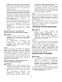
9-1. Lock nut
9-2. Depressed center wheel
9-3. Inner flange
10-1. Lock nut wrench
10-2. Shaft lock
11-1. Ezynut
11-2. Abrasive wheel
11-3. Inner flange
11-4. Spindle
12-1. Shaft lock
13-1. Arrow
13-2. Notch
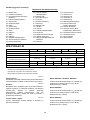
15-1. Lock nut
15-2. Flex wheel
15-3. Plastic pad
15-4. Inner flange
16-1. Sanding lock nut
16-2. Abrasive disc
16-3. Rubber pad
17-1. Marking A
17-2. Marking B
17-3. Marking C
17-4. Marking D
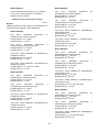
19-1. Lock nut
19-2. Abrasive cut-off wheel/diamond
wheel
19-3. Inner flange
19-4. Wheel guard for abrasive cut-off
wheel/diamond wheel
20-1. Wire cup brush
21-1. Wire wheel brush
22-1. Exhaust vent
22-2. Inhalation vent
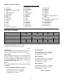
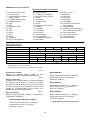
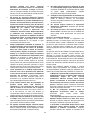
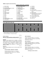
SPECIFICATIONS
Model GA4040C GA4041C GA4540C GA4541C GA5040C GA5041C
GA6040C
Wheel diameter 100 mm (4") 115 mm (4-1/2") 125 mm (5")
150 mm (6")
Max. wheel thickness 6.4 mm
Spindle thread M10 M14 or 5/8" (country specific)
Rated speed (n) / No load speed (n0) 11,000 min-1 11,000 min-1 11,000 min-1
9,000 min
-1
Overall length 303 mm 325 mm 303 mm 325 mm 303 mm 325 mm 303 mm
Net weight 2.3 kg 2.6 kg 2.5 kg 2.7 kg 2.5 kg 2.7 kg 2.6 kg
Safety class /II
• Due to our continuing program of research and development, the specifications herein are subject to change without notice.
• Specifications may differ from country to country.
• Weight according to EPTA-Procedure 01/2003
ENE048-1
Intended use
The tool is intended for grinding, sanding and cutting of
metal and stone materials without the use of water.
ENF002-2
Power supply
The tool should be connected only to a power supply of
the same voltage as indicated on the nameplate, and
can only be operated on single-phase AC supply. They
are double-insulated and can, therefore, also be used
from sockets without earth wire.
ENG905-1
Noise
The typical A-weighted noise level determined according
to EN60745:
Model GA4040C, GA4540C, GA5040C
Sound pressure level (LpA) : 86 dB (A)
Sound power level (LWA) : 97 dB (A)
Uncertainty (K) : 3 dB (A)
Model GA6040C
Sound pressure level (LpA) : 87 dB (A)
Sound power level (LWA) : 98 dB (A)
Uncertainty (K) : 3 dB (A)
Model GA4541C
Sound pressure level (LpA) : 83 dB (A)
Sound power level (LWA) : 94 dB (A)
Uncertainty (K) : 3 dB (A)
Model GA5041C
Sound pressure level (LpA) : 84 dB (A)
Sound power level (LWA) : 95 dB (A)
Uncertainty (K) : 3 dB (A)
Wear ear protection

5
ENG900-1
Vibration
The vibration total value (tri-axial vector sum)
determined according to EN60745:
Model GA4040C
Work mode : surface grinding with normal side grip
Vibration emission (ah,AG) : 5.0 m/s2
Uncertainty (K) : 1.5 m/s2
Work mode : surface grinding with anti vibration
side grip
Vibration emission (ah,AG) : 5.0 m/s2
Uncertainty (K) : 1.5 m/s2
Work mode : disc sanding with normal side grip
Vibration emission (ah,DS) : 3.0 m/s2
Uncertainty (K) : 1.5 m/s2
Work mode : disc sanding with anti vibration side
grip
Vibration emission (ah,DS) : 2.5 m/s2 or less
Uncertainty (K) : 1.5 m/s2
Model GA4540C
Work mode : surface grinding with normal side grip
Vibration emission (ah,AG) : 6.0 m/s2
Uncertainty (K) : 1.5 m/s2
Work mode : surface grinding with anti vibration
side grip
Vibration emission (ah,AG) : 5.5 m/s2
Uncertainty (K) : 1.5 m/s2
Work mode : disc sanding with normal side grip
Vibration emission (ah,DS) : 2.5 m/s2
Uncertainty (K) : 1.5 m/s2
Work mode : disc sanding with anti vibration side
grip
Vibration emission (ah,DS) : 2.5 m/s2
Uncertainty (K) : 1.5 m/s2
Model GA5040C
Work mode : surface grinding with normal side grip
Vibration emission (ah,AG) : 6.5 m/s2
Uncertainty (K) : 1.5 m/s2
Work mode : surface grinding with anti vibration
side grip
Vibration emission (ah,AG) : 5.5 m/s2
Uncertainty (K) : 1.5 m/s2
Work mode : disc sanding with normal side grip
Vibration emission (ah,DS) : 2.5 m/s2
Uncertainty (K) : 1.5 m/s2
Work mode : disc sanding with anti vibration side
grip
Vibration emission (ah,DS) : 2.5 m/s2
Uncertainty (K) : 1.5 m/s2
Model GA6040C
Work mode : surface grinding with normal side grip
Vibration emission (ah,AG) : 6.5 m/s2
Uncertainty (K) : 1.5 m/s2
Work mode : surface grinding with anti vibration
side grip
Vibration emission (ah,AG) : 6.0 m/s2
Uncertainty (K) : 1.5 m/s2
Work mode : disc sanding with normal side grip
Vibration emission (ah,DS) : 2.5 m/s2
Uncertainty (K) : 1.5 m/s2
Work mode : disc sanding with anti vibration side
grip
Vibration emission (ah,DS) : 2.5 m/s2 or less
Uncertainty (K) : 1.5 m/s2
Model GA4541C
Work mode : surface grinding with normal side grip
Vibration emission (ah,AG) : 6.5 m/s2
Uncertainty (K) : 1.5 m/s2
Work mode : surface grinding with anti vibration
side grip
Vibration emission (ah,AG) : 5.5 m/s2
Uncertainty (K) : 1.5 m/s2
Work mode : disc sanding with normal side grip
Vibration emission (ah,DS) : 2.5 m/s2 or less
Uncertainty (K) : 1.5 m/s2
Work mode : disc sanding with anti vibration side
grip
Vibration emission (ah,DS) : 2.5 m/s2 or less
Uncertainty (K) : 1.5 m/s2
Model GA5041C
Work mode : surface grinding with normal side grip
Vibration emission (ah,AG) : 7.0 m/s2
Uncertainty (K) : 1.5 m/s2
Work mode : surface grinding with anti vibration
side grip
Vibration emission (ah,AG) : 6.0 m/s2
Uncertainty (K) : 1.5 m/s2
Work mode : disc sanding with normal side grip
Vibration emission (ah,DS) : 2.5 m/s2 or less
Uncertainty (K) : 1.5 m/s2

6
Work mode : disc sanding with anti vibration side
grip
Vibration emission (ah,DS) : 2.5 m/s2 or less
Uncertainty (K) : 1.5 m/s2
ENG902-1
• The declared vibration emission value has been
measured in accordance with the standard test
method and may be used for comparing one tool
with another.
• The declared vibration emission value may also be
used in a preliminary assessment of exposure.
• The declared vibration emission value is used for
main applications of the power tool. However if the
power tool is used for other applications, the
vibration emission value may be different.
WARNING:
• The vibration emission during actual use of the
power tool can differ from the declared emission
value depending on the ways in which the tool is
used.
• Be sure to identify safety measures to protect the
operator that are based on an estimation of
exposure in the actual conditions of use (taking
account of all parts of the operating cycle such as
the times when the tool is switched off and when it
is running idle in addition to the trigger time).
ENH101-16
For European countries only
EC Declaration of Conformity
We Makita Corporation as the responsible
manufacturer declare that the following Makita
machine(s):
Designation of Machine:
Angle Grinder
Model No./ Type: GA4040C, GA4540C, GA5040C,
GA6040C, GA4541C, GA5041C
are of series production and
Conforms to the following European Directives:
2006/42/EC
And are manufactured in accordance with the following
standards or standardised documents:
EN60745
The technical documentation is kept by:
Makita International Europe Ltd.
Technical Department,
Michigan Drive, Tongwell,
Milton Keynes, Bucks MK15 8JD, England
30.8.2011
000230
Tomoyasu Kato
Director
Makita Corporation
3-11-8, Sumiyoshi-cho,
Anjo, Aichi, 446-8502, JAPAN
GEA010-1
General Power Tool Safety
Warnings
WARNING Read all safety warnings and all
instructions. Failure to follow the warnings and
instructions may result in electric shock, fire and/or
serious injury.
Save all warnings and instructions for
future reference.
GEB033-7
GRINDER SAFETY WARNINGS
Safety Warnings Common for Grinding, Sanding,
Wire Brushing, or Abrasive Cutting-Off Operations:
1. This power tool is intended to function as a
grinder, sander, wire brush or cut-off tool.
Read all safety warnings, instructions,
illustrations and specifications provided with
this power tool. Failure to follow all instructions
listed below may result in electric shock, fire
and/or serious injury.
2. Operations such as polishing are not
recommended to be performed with this
power tool. Operations for which the power tool
was not designed may create a hazard and cause
personal injury.
3. Do not use accessories which are not
specifically designed and recommended by
the tool manufacturer. Just because the
accessory can be attached to your power tool, it
does not assure safe operation.
4. The rated speed of the accessory must be at
least equal to the maximum speed marked on
the power tool. Accessories running faster than
their rated speed can break and fly apart.
5. The outside diameter and the thickness of
your accessory must be within the capacity
rating of your power tool. Incorrectly sized
accessories cannot be adequately guarded or
controlled.
6. Threaded mounting of accessories must
match the grinder spindle thread. For
accessories mounted by flanges, the arbour
hole of the accessory must fit the locating
diameter of the flange. Accessories that do not
match the mounting hardware of the power tool

7
will run out of balance, vibrate excessively and
may cause loss of control.
7. Do not use a damaged accessory. Before each
use inspect the accessory such as abrasive
wheels for chips and cracks, backing pad for
cracks, tear or excess wear, wire brush for
loose or cracked wires. If power tool or
accessory is dropped, inspect for damage or
install an undamaged accessory. After
inspecting and installing an accessory,
position yourself and bystanders away from
the plane of the rotating accessory and run the
power tool at maximum no-load speed for one
minute. Damaged accessories will normally
break apart during this test time.
8. Wear personal protective equipment.
Depending on application, use face shield,
safety goggles or safety glasses. As
appropriate, wear dust mask, hearing
protectors, gloves and workshop apron
capable of stopping small abrasive or
workpiece fragments. The eye protection must
be capable of stopping flying debris generated by
various operations. The dust mask or respirator
must be capable of filtrating particles generated
by your operation. Prolonged exposure to high
intensity noise may cause hearing loss.
9. Keep bystanders a safe distance away from
work area. Anyone entering the work area
must wear personal protective equipment.
Fragments of workpiece or of a broken accessory
may fly away and cause injury beyond immediate
area of operation.
10. Hold the power tool by insulated gripping
surfaces only, when performing an operation
where the cutting accessory may contact
hidden wiring or its own cord. Cutting
accessory contacting a "live" wire may make
exposed metal parts of the power tool "live" and
could give the operator an electric shock.
11. Position the cord clear of the spinning
accessory. If you lose control, the cord may be
cut or snagged and your hand or arm may be
pulled into the spinning accessory.
12. Never lay the power tool down until the
accessory has come to a complete stop. The
spinning accessory may grab the surface and pull
the power tool out of your control.
13. Do not run the power tool while carrying it at
your side. Accidental contact with the spinning
accessory could snag your clothing, pulling the
accessory into your body.
14. Regularly clean the power tool’s air vents. The
motor’s fan will draw the dust inside the housing
and excessive accumulation of powdered metal
may cause electrical hazards.
15. Do not operate the power tool near flammable
materials. Sparks could ignite these materials.
16. Do not use accessories that require liquid
coolants. Using water or other liquid coolants
may result in electrocution or shock.
Kickback and Related Warnings
Kickback is a sudden reaction to a pinched or snagged
rotating wheel, backing pad, brush or any other
accessory. Pinching or snagging causes rapid stalling of
the rotating accessory which in turn causes the
uncontrolled power tool to be forced in the direction
opposite of the accessory’s rotation at the point of the
binding.
For example, if an abrasive wheel is snagged or pinched
by the workpiece, the edge of the wheel that is entering
into the pinch point can dig into the surface of the
material causing the wheel to climb out or kick out. The
wheel may either jump toward or away from the operator,
depending on direction of the wheel’s movement at the
point of pinching. Abrasive wheels may also break under
these conditions.
Kickback is the result of power tool misuse and/or
incorrect operating procedures or conditions and can be
avoided by taking proper precautions as given below.
a) Maintain a firm grip on the power tool and
position your body and arm to allow you to
resist kickback forces. Always use auxiliary
handle, if provided, for maximum control over
kickback or torque reaction during start-up.
The operator can control torque reactions or
kickback forces, if proper precautions are taken.
b) Never place your hand near the rotating
accessory. Accessory may kickback over your
hand.
c) Do not position your body in the area where
power tool will move if kickback occurs.
Kickback will propel the tool in direction opposite to
the wheel’s movement at the point of snagging.
d) Use special care when working corners,
sharp edges etc. Avoid bouncing and snagging
the accessory. Corners, sharp edges or bouncing
have a tendency to snag the rotating accessory
and cause loss of control or kickback.
e) Do not attach a saw chain woodcarving
blade or toothed saw blade. Such blades create
frequent kickback and loss of control.
Safety Warnings Specific for Grinding and Abrasive
Cutting-Off Operations:
a) Use only wheel types that are recommended
for your power tool and the specific guard
designed for the selected wheel. Wheels for
which the power tool was not designed cannot be
adequately guarded and are unsafe.
b) The grinding surface of centre depressed
wheels must be mounted below the plane of
the guard lip. An improperly mounted wheel that
projects through the plane of the guard lip cannot
be adequately protected.
c) The guard must be securely attached to the
power tool and positioned for maximum safety,

8
so the least amount of wheel is exposed
towards the operator. The guard helps to protect
the operator from broken wheel fragments,
accidental contact with wheel and sparks that
could ignite clothing.
d) Wheels must be used only for recommended
applications. For example: do not grind with
the side of cut-off wheel. Abrasive cut-off wheels
are intended for peripheral grinding, side forces
applied to these wheels may cause them to
shatter.
e) Always use undamaged wheel flanges that
are of correct size and shape for your selected
wheel. Proper wheel flanges support the wheel
thus reducing the possibility of wheel breakage.
Flanges for cut-off wheels may be different from
grinding wheel flanges.
f) Do not use worn down wheels from larger
power tools. Wheel intended for larger power tool
is not suitable for the higher speed of a smaller tool
and may burst.
Additional Safety Warnings Specific for Abrasive
Cutting-Off Operations:
a) Do not “jam” the cut-off wheel or apply
excessive pressure. Do not attempt to make an
excessive depth of cut. Overstressing the wheel
increases the loading and susceptibility to twisting
or binding of the wheel in the cut and the possibility
of kickback or wheel breakage.
b) Do not position your body in line with and
behind the rotating wheel. When the wheel, at
the point of operation, is moving away from your
body, the possible kickback may propel the
spinning wheel and the power tool directly at you.
c) When wheel is binding or when interrupting
a cut for any reason, switch off the power tool
and hold the power tool motionless until the
wheel comes to a complete stop. Never attempt
to remove the cut-off wheel from the cut while
the wheel is in motion otherwise kickback may
occur. Investigate and take corrective action to
eliminate the cause of wheel binding
d) Do not restart the cutting operation in the
workpiece. Let the wheel reach full speed and
carefully re-enter the cut. The wheel may bind,
walk up or kickback if the power tool is restarted in
the workpiece.
e) Support panels or any oversized workpiece
to minimize the risk of wheel pinching and
kickback. Large workpieces tend to sag under
their own weight. Supports must be placed under
the workpiece near the line of cut and near the
edge of the workpiece on both sides of the wheel.
f) Use extra caution when making a “pocket
cut” into existing walls or other blind areas.
The protruding wheel may cut gas or water pipes,
electrical wiring or objects that can cause kickback.
Safety Warnings Specific for Sanding Operations:
a) Do not use excessively oversized sanding
disc paper. Follow manufacturers
recommendations, when selecting sanding
paper. Larger sanding paper extending beyond the
sanding pad presents a laceration hazard and may
cause snagging, tearing of the disc or kickback.
Safety Warnings Specific for Wire Brushing
Operations:
a) Be aware that wire bristles are thrown by the
brush even during ordinary operation. Do not
overstress the wires by applying excessive
load to the brush. The wire bristles can easily
penetrate light clothing and/or skin.
b) If the use of a guard is recommended for
wire brushing, do not allow interference of the
wire wheel or brush with the guard. Wire wheel
or brush may expand in diameter due to work load
and centrifugal forces.
Additional safety warnings:
17. When using depressed centre grinding wheels,
be sure to use only fiberglass-reinforced
wheels.
18. NEVER USE Stone Cup type wheels with this
grinder. This grinder is not designed for these
types of wheels and the use of such a product
may result in serious personal injury.
19. Be careful not to damage the spindle, the
flange (especially the installing surface) or the
lock nut. Damage to these parts could result in
wheel breakage.
20. Make sure the wheel is not contacting the
workpiece before the switch is turned on.
21. Before using the tool on an actual workpiece,
let it run for a while. Watch for vibration or
wobbling that could indicate poor installation
or a poorly balanced wheel.
22. Use the specified surface of the wheel to
perform the grinding.
23. Do not leave the tool running. Operate the tool
only when hand-held.
24. Do not touch the workpiece immediately after
operation; it may be extremely hot and could
burn your skin.
25. Observe the instructions of the manufacturer
for correct mounting and use of wheels.
Handle and store wheels with care.
26. Do not use separate reducing bushings or
adaptors to adapt large hole abrasive wheels.
27. Use only flanges specified for this tool.
28. For tools intended to be fitted with threaded
hole wheel, ensure that the thread in the wheel
is long enough to accept the spindle length.
29. Check that the workpiece is properly
supported.
30. Pay attention that the wheel continues to
rotate after the tool is switched off.

9
31. If working place is extremely hot and humid,
or badly polluted by conductive dust, use a
short-circuit breaker (30 mA) to assure
operator safety.
32. Do not use the tool on any materials
containing asbestos.
33. When use cut-off wheel, always work with the
dust collecting wheel guard required by
domestic regulation.
34. Cutting discs must not be subjected to any
lateral pressure.
SAVE THESE INSTRUCTIONS.
WARNING:
DO NOT let comfort or familiarity with product
(gained from repeated use) replace strict adherence
to safety rules for the subject product. MISUSE or
failure to follow the safety rules stated in this
instruction manual may cause serious personal
injury.
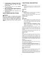
FUNCTIONAL DESCRIPTION
CAUTION:
• Always be sure that the tool is switched off and
unplugged before adjusting or checking function on
the tool.
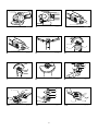
Shaft lock
Fig.1
CAUTION:
• Never actuate the shaft lock when the spindle is
moving. The tool may be damaged.
Press the shaft lock to prevent spindle rotation when
installing or removing accessories.
Switch action
Fig.2
CAUTION:
• Before plugging in the tool, always check to see
that the slide switch actuates properly and returns
to the "OFF" position when the rear of the slide
switch is depressed.
• Switch can be locked in "ON" position for ease of
operator comfort during extended use. Apply
caution when locking tool in "ON" position and
maintain firm grasp on tool.
To start the tool, slide the slide switch toward the "I (ON)"
position by pushing the rear of the slide switch. For
continuous operation, press the front of the slide switch
to lock it.
To stop the tool, press the rear of the slide switch, then
slide it toward the "O (OFF)" position.
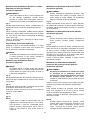
Indication lamp
Fig.3
The indication lamp lights up green when the tool is
plugged. If the indication lamp does not light up, the
mains cord or the controller may be defective. The
indication lamp is lit but the tool does not start even if the
tool is switched on, the carbon brushes may be worn out,
or the controller, the motor or the ON/OFF switch may be
defective.
Unintentional restart proof
The tool does not start with the switch being lock-on
even when the tool is plugged.
At this time, the indication lamp flickers red and shows
the unintentional restart proof device is on function.
To cancel the unintentional restart proof, return the slide
switch to "O(OFF)" position.
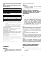
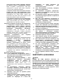
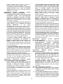
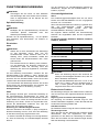
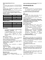
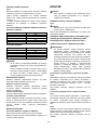
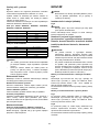
Speed adjusting dial
Fig.4
The rotating speed can be changed by turning the speed
adjusting dial to a given number setting from 1 to 5.
Higher speed is obtained when the dial is turned in the
direction of number 5. And lower speed is obtained when
it is turned in the direction of number 1.

10
Refer to the below table for the relationship between the
number settings on the dial and the approximate rotating
speed.
For model GA4040C, GA4540C, GA5040C, GA4041C,
GA4541C, GA5041C
Number min
-1
(R.P.M.)
1 2,800
2 4,000
3 6,000
4 8,000
511,000
012752
For model GA6040C
Number min
-1
(R.P.M.)
1 4,000
2 5,000
3 6,000
4 7,000
59,000
012756
CAUTION:
• If the tool is operated continuously at low speeds
for a long time, the motor will get overloaded and
heated up.
• The speed adjusting dial can be turned only as far
as 5 and back to 1. Do not force it past 5 or 1, or
the speed adjusting function may no longer work.
Electronic function
The tools equipped with electronic function are easy to
operate because of the following features.
Constant speed control
Constant speed control provides fine finish by keeping
the rotating speed constant under the loaded condition.
Soft start feature
Soft start feature suppresses starting shock.
Overload protector
When the load on the tool exceeds admissible levels,
power to the motor is reduced to protect the motor from
overheating. When the load returns to admissible levels,
the tool will operate as normal.
Mechanical brake
For model GA4041C, GA4541C, GA5041C
Mechanical brake is activated after the tool is switched
off.
The brake does not work when the power supply is shut
down with the switch still on.
ASSEMBLY
CAUTION:
• Always be sure that the tool is switched off and
unplugged before carrying out any work on the
tool.
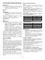
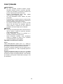
Installing side grip (handle)
Fig.5
CAUTION:
• Always be sure that the side grip is installed
securely before operation.
Screw the side grip securely on the position of the tool
as shown in the figure.
Installing or removing wheel guard (For
depressed center wheel, flap disc, flex wheel,
wire wheel brush / abrasive cut-off wheel,
diamond wheel)
WARNING:
• When using a depressed center wheel, flap disc,
flex wheel or wire wheel brush, the wheel guard
must be fitted on the tool so that the closed side of
the guard always points toward the operator.
• When using an abrasive cut-off / diamond wheel,
be sure to use only the special wheel guard
designed for use with cut-off wheels. (In some
European countries, when using a diamond wheel,
the ordinary guard can be used. Follow the
regulations in your country.)
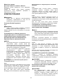
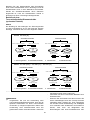
For tool with locking screw type wheel guard
Fig.6
Mount the wheel guard with the protrusions on the wheel
guard band aligned with the notches on the bearing box.
Then rotate the wheel guard around 180 ゚
counterclockwise. Be sure to tighten the screw securely.
To remove wheel guard, follow the installation procedure
in reverse.
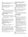
For tool with clamp lever type wheel guard
Fig.7
Pull the lever in the direction of the arrow after loosening
the screw. Mount the wheel guard with the protrusions
on the wheel guard band aligned with the notches on the
bearing box. Then rotate the wheel guard around 180 ゚.
Fig.8
Tighten the wheel guard with fastening the screw after
pulling lever in the direction of the arrow. The setting
angle of the wheel guard can be adjusted with the lever.
To remove wheel guard, follow the installation procedure
in reverse.
Installing or removing depressed center
wheel or flap disc (optional accessory)
WARNING:
• When using a depressed center wheel or flap disc,
the wheel guard must be fitted on the tool so that
the closed side of the guard always points toward
the operator.

11
Fig.9
Mount the inner flange onto the spindle. Fit the
wheel/disc on the inner flange and screw the lock nut
onto the spindle.
Fig.10
To tighten the lock nut, press the shaft lock firmly so that
the spindle cannot revolve, then use the lock nut wrench
and securely tighten clockwise.
To remove the wheel, follow the installation procedure in
reverse.
Super flange (Optional accessory)
Models with the letter F are standard-equipped with
Super flange. Only 1/3 of efforts needed to undo lock nut,
compared with conventional type.
CAUTION:
• Do not use super flange for models equipped with
the mechanical brake. Otherwise it may loosen
when the brake is activated.
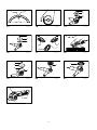
Installing or removing Ezynut
(optional accessory)
CAUTION:
• Do not use Ezynut with Super Flange or angle
grinder with “F” on the end of the model No. Those
flanges are so thick that the entire thread cannot
be retained by the spindle.
Fig.11
Mount inner flange, abrasive wheel and Ezynut onto the
spindle so that Makita Logo on Ezynut faces outside.
Fig.12
Press shaft lock firmly and tighten Ezynut by turning the
abrasive wheel clockwise as far as it turns.
Turn the outside ring of Ezynut counterclockwise to
loosen.
Fig.13
Fig.14
NOTE:
•
Ezynut can be loosened by hand as long as the
arrow points the notch. Otherwise a lock nut wrench
is required to loosen it. Insert one pin of the wrench
into a hole and turn Ezynut counterclockwise.
Installing or removing flex wheel
(optional accessory)
WARNING:
• Always use supplied guard when flex wheel is on
tool. Wheel can shatter during use and guard helps
to reduce chances of personal injury.
Fig.15
Follow instructions for depressed center wheel but also
use plastic pad over wheel. See order of assembly on
accessories page in this manual.
Installing or removing abrasive disc
(optional accessory)
NOTE:
• Use sander accessories specified in this manual.
These must be purchased separately.
Fig.16
Mount the rubber pad onto the spindle. Fit the disc on
the rubber pad and screw the sanding lock nut onto the
spindle. To tighten the sanding lock nut, press the shaft
lock firmly so that the spindle cannot revolve, then use
the lock nut wrench and securely tighten clockwise.
To remove the disc, follow the installation procedure in
reverse.
Installing or removing dust cover attachment
(Optional accessory)
WARNING:
• Always be sure that the tool is switched off and
unplugged before installing or removing the
dust cover attachment. Failure to do so causes
damage to the tool or a personal injury.
There are four pieces of dust cover attachment and each
is used in one of different positions.
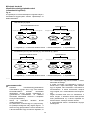
Fig.17
Set the dust cover attachment so that the marking (A, B,
C or D) places as shown. Snap its pins in the vents.
Dust cover attachment can be removed by hand.
NOTE:
• Clean out the dust cover attachment when it is
clogged with dust or foreign matters. Continuing
operation with a clogged dust cover attachment will
damage the tool.
OPERATION
WARNING:
• It should never be necessary to force the tool. The
weight of the tool applies adequate pressure.
Forcing and excessive pressure could cause
dangerous wheel breakage.
• ALWAYS replace wheel if tool is dropped while
grinding.
• NEVER bang or hit grinding disc or wheel onto
work.
• Avoid bouncing and snagging the wheel, especially
when working corners, sharp edges etc. This can
cause loss of control and kickback.
• NEVER use tool with wood cutting blades and
other saw blades. Such blades when used on a
grinder frequently kick and cause loss of control
leading to personal injury.
CAUTION:
• Never switch on the tool when it is in contact with
the workpiece, it may cause an injury to operator.

12
• Always wear safety goggles or a face shield during
operation.
• After operation, always switch off the tool and wait
until the wheel has come to a complete stop before
putting the tool down.
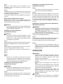
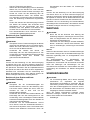
Grinding and sanding operation
Fig.18
ALWAYS hold the tool firmly with one hand on housing
and the other on the side handle. Turn the tool on and
then apply the wheel or disc to the workpiece.
In general, keep the edge of the wheel or disc at an
angle of about 15 ゚ to the workpiece surface.
During the break-in period with a new wheel, do not work
the grinder in the B direction or it will cut into the
workpiece. Once the edge of the wheel has been
rounded off by use, the wheel may be worked in both A
and B direction.

13
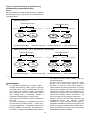
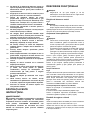
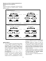
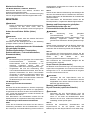
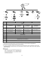
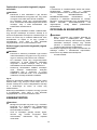
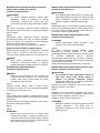
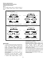
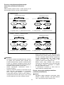
Operation with abrasive cut-off / diamond
wheel (optional accessory)
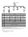
Fig.19
The direction for mounting the lock nut and the inner
flange varies by wheel thickness.
Refer to the table below.
Abrasive cut-off wheelDiamond wheel
Thickness: Less than 4 mm (5/32")Thickness: 4 mm (5/32") or more
16 mm (5/8")20 mm (13/16")
22.23 mm (7/8")
Abrasive cut-off wheelDiamond wheel
Thickness: Less than 4 mm (5/32")Thickness: 4 mm (5/32") or more
Thickness: Less than 4 mm (5/32")Thickness: 4 mm (5/32") or more Thickness: Less than 4 mm (5/32")Thickness: 4 mm (5/32") or more
22.23 mm (7/8")22.23 mm (7/8")22.23 mm (7/8")
16 mm (5/8")
20 mm (13/16")
1
2
3
1
4
3
100 mm (4") model
115 mm (4 - 1/2") / 125 mm (5") / 150 mm (6") model
1
2
3
1
4
3
Lock nutAbrasive cut-off wheelInner flangeDiamond wheel1.2.3.4.
Lock nutAbrasive cut-off wheelInner flangeDiamond wheel1.2.3.4.
012746
WARNING:
• When using an abrasive cut-off / diamond wheel,
be sure to use only the special wheel guard
designed for use with cut-off wheels. (In some
European countries, when using a diamond wheel,
the ordinary guard can be used. Follow the
regulations in your country.)
• NEVER use cut-off wheel for side grinding.
• Do not "jam" the wheel or apply excessive
pressure. Do not attempt to make an excessive
depth of cut. Overstressing the wheel increases
the loading and susceptibility to twisting or binding
of the wheel in the cut and the possibility of
kickback, wheel breakage and overheating of the
motor may occur.
• Do not start the cutting operation in the workpiece.
Let the wheel reach full speed and carefully enter
into the cut moving the tool forward over the
workpiece surface. The wheel may bind, walk up
or kickback if the power tool is started in the
workpiece.
• During cutting operations, never change the angle
of the wheel. Placing side pressure on the cut-off
wheel (as in grinding) will cause the wheel to crack
and break, causing serious personal injury.
• A diamond wheel shall be operated perpendicular
to the material being cut.

14
Operation with wire cup brush
(optional accessory)
CAUTION:
• Check operation of brush by running tool with no
load, insuring that no one is in front of or in line with
brush.
• Do not use brush that is damaged, or which is out
of balance. Use of damaged brush could increase
potential for injury from contact with broken brush
wires.
Fig.20
Unplug tool and place it upside down allowing easy
access to spindle. Remove any accessories on spindle.
Thread wire cup brush onto spindle and tighten with
supplied wrench. When using brush, avoid applying too
much pressure which causes over bending of wires,
leading to premature breakage.
Operation with wire wheel brush
(optional accessory)
CAUTION:
• Check operation of wire wheel brush by running
tool with no load, insuring that no one is in front of
or in line with the wire wheel brush.
• Do not use wire wheel brush that is damaged, or
which is out of balance. Use of damaged wire
wheel brush could increase potential for injury from
contact with broken wires.
• ALWAYS use guard with wire wheel brushes,
assuring diameter of wheel fits inside guard. Wheel
can shatter during use and guard helps to reduce
chances of personal injury.
Fig.21
Unplug tool and place it upside down allowing easy
access to spindle. Remove any accessories on spindle.
Thread wire wheel brush onto spindle and tighten with
the wrenches.
When using wire wheel brush, avoid applying too much
pressure which causes over bending of wires, leading to
premature breakage.
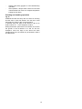
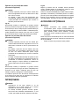
MAINTENANCE
CAUTION:
• Always be sure that the tool is switched off and
unplugged before attempting to perform inspection
or maintenance.
• Never use gasoline, benzine, thinner, alcohol or
the like. Discoloration, deformation or cracks may
result.
Fig.22
The tool and its air vents have to be kept clean.
Regularly clean the tool's air vents or whenever the
vents start to become obstructed.
To maintain product SAFETY and RELIABILITY, repairs,
carbon brush inspection and replacement, any other
maintenance or adjustment should be performed by
Makita Authorized Service Centers, always using Makita
replacement parts.
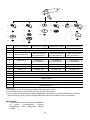
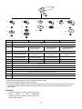
OPTIONAL ACCESSORIES
CAUTION:
• These accessories or attachments are
recommended for use with your Makita tool
specified in this manual. The use of any other
accessories or attachments might present a risk of
injury to persons. Only use accessory or
attachment for its stated purpose.
If you need any assistance for more details regarding
these accessories, ask your local Makita Service Center.
• Dust cover attachment

15
2
5
22
11
12
4
3
5
6
7
8
9
10
1
13
3
14
5
3
1
2
3
4
5
6
7
8
9
10
11
12
13
14
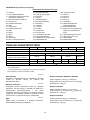
-
100 mm (4") model115 mm (4-1/2") model125 mm (5") model150 mm (6") model
Grip 36
Wheel Guard (for grinding wheel)
Plastic pad
Flex wheel
Rubber pad 76
Abrasive disc
Wire wheel brush
Plastic pad Plastic pad
Flex wheelFlex wheel
Rubber pad 100 Rubber pad 115 Rubber pad 125
Wire cup brush
Abrasive cut-off wheel/Diamond wheel
Note:
Inner flange Inner flange
Super flange *1
Inner flange
Super flange *1
Inner flange
Super flange *1
Depressed center wheel/Flap disc
Lock nut Lock nut
Ezy nut *2
Lock nut
Ezy nut *2
Lock nut
Ezy nut *2
Sanding lock nut
Wheel Guard (for cut-off wheel) *3
*2 Do not use Super flange and Ezynut together.
Lock nut wrench
-
-
*3 In some European countries, when using a diamond wheel, the ordinary guard can be used instead of the
special guard covering the both side of the wheel. Follow the regulations in your country.
*1 Do not use Super flange with a grinder equipped with a brake function.
013977
NOTE:
• Some items in the list may be included in the tool
package as standard accessories. They may differ
from country to country.

16
УКРАЇНСЬКА (Оригінальні інструкції)
Пояснення до загального виду
1-1. Фіксатор
2-1. Повзунковий перемикач
3-1. Індикаторна лампочка (на диску
регулювання швидкості)
4-1. Диск регулювання швидкості
6-1. Кожух диска
6-2. Коробка підшипника
6-3. Гвинт
7-1. Кожух диска
7-2. Коробка підшипника
7-3. Гвинт
7-4. Важіль
8-1. Гвинт
8-2. Важіль
9-1. Контргайка
9-2. Диск з увігнутим центром
9-3. Внутрішній фланець
10-1. Ключ для контргайки
10-2. Фіксатор
11-1. Ezynut
11-2. Абразивний диск
11-3. Внутрішній фланець
11-4. Шпиндель
12-1. Фіксатор
13-1. Стрілка
13-2. Прорізь
15-1. Контргайка
15-2. Гнучкий диск
15-3. Пластикова підкладка
15-4. Внутрішній фланець
16-1. Шліфувальна стопорна гайка
16-2. Абразивний диск
16-3. Гумова підкладка
17-1. Мітка "A"
17-2. Мітка "B"
17-3. Мітка "C"
17-4. Мітка "D"
19-1. Контргайка
19-2. Абразивний відрізний
диск/алмазний диск
19-3. Внутрішній фланець
19-4. Кожух диска для абразивного
відрізного диска/алмазного
диска
20-1. Чашоподібна дротяна щітка
21-1. Дискова дротяна щітка
22-1. Повітровідвід
22-2. Вдихальний клапан
ТЕХНІЧНІ ХАРАКТЕРИСТИКИ
Модель GA4040C GA4041C GA4540C GA4541C GA5040C GA5041C
GA6040C
Діаметр диска 100 мм (4") 115 мм (4-1/2") 125 мм (5")
150 мм (6")
Макс. товщина диска 6,4 мм
Різьба шпинделя M10 M14 або 5/8" (залежно від країни)
Номінальна швидкість (n) /
швидкість без навантаження (n0) 11000 хв.-1 11000 хв.-1 11000 хв.-1
9000 хв.
-1
Загальна довжина 303 мм 325 мм 303 мм 325 мм 303 мм 325 мм 303 мм
Чиста вага 2,3 кг 2,6 кг 2,5 кг 2,7 кг 2,5 кг 2,7 кг 2,6 кг
Клас безпеки /II
• Через те, що ми не припиняємо програми досліджень і розвитку, наведені тут технічні характеристики можуть бути змінені
без попередження.
• У різних країнах технічні характеристики можуть бути різними.
• Вага відповідно до EPTA-Procedure 01/2003
ENE048-1
Призначення
Інструмент призначений для шліфування, обробка
піском та різання металу та каміння без
використання води.
ENF002-2
Джерело живлення
Інструмент можна підключати лише до джерела
живлення, що має напругу, зазначену в табличці із
заводськими характеристиками, і він може
працювати лише від однофазного джерела змінного
струму. Він має подвійну ізоляцію, а отже може також
підключатися до розеток без дроту заземлення.
ENG905-1
Шум
Рівень шуму за шкалою А у типовому виконанні,
визначений відповідно до EN60745:
Модель GA4040C, GA4540C, GA5040C
Рівень звукового тиску (LpA): 86 дБ (A)
Рівень акустичної потужності (LWA): 97 дБ (A)
Похибка (K) : 3 дБ (A)
Модель GA6040C
Рівень звукового тиску (LpA): 87 дБ (A)
Рівень акустичної потужності (LWA): 98 дБ (A)
Похибка (K) : 3 дБ (A)
Модель GA4541C
Рівень звукового тиску (LpA): 83 дБ (A)
Рівень акустичної потужності (LWA): 94 дБ (A)
Похибка (K) : 3 дБ (A)

17
Модель GA5041C
Рівень звукового тиску (LpA): 84 дБ (A)
Рівень акустичної потужності (LWA): 95 дБ (A)
Похибка (K) : 3 дБ (A)
Користуйтеся засобами захисту слуху
ENG900-1
Вібрація
Загальна величина вібрації (сума трьох векторів)
визначена згідно з EN60745:
Модель GA4040C
Режим роботи: шліфування поверхні за
допомогою звичайного бічного держака
Вібрація (ah.,AG) : 5,0 м/с2
Похибка (К): 1,5 м/с2
Режим роботи: шліфування поверхні за
допомогою вібростійкого бічного держака
Вібрація (ah.,AG) : 5,0 м/с2
Похибка (К): 1,5 м/с2
Режим роботи: шліфування диском за
допомогою звичайного бічного держака
Вібрація (ah,DS): 3,0 м/с2
Похибка (К): 1,5 м/с2
Режим роботи: шліфування диском за
допомогою вібростійкого бічного держака
Вібрація (ah.,DS): 2,5 м/с2 або менше
Похибка (К): 1,5 м/с2
Модель GA4540C
Режим роботи: шліфування поверхні за
допомогою звичайного бічного держака
Вібрація (ah.,AG) : 6,0 м/с2
Похибка (К): 1,5 м/с2
Режим роботи: шліфування поверхні за
допомогою вібростійкого бічного держака
Вібрація (ah.,AG) : 5,5 м/с2
Похибка (К): 1,5 м/с2
Режим роботи: шліфування диском за
допомогою звичайного бічного держака
Вібрація (ah,DS): 2,5 м/с2
Похибка (К): 1,5 м/с2
Режим роботи: шліфування диском за
допомогою вібростійкого бічного держака
Вібрація (ah,DS): 2,5 м/с2
Похибка (К): 1,5 м/с2
Модель GA5040C
Режим роботи: шліфування поверхні за
допомогою звичайного бічного держака
Вібрація (ah.,AG) : 6,5 м/с2
Похибка (К): 1,5 м/с2
Режим роботи: шліфування поверхні за
допомогою вібростійкого бічного держака
Вібрація (ah.,AG) : 5,5 м/с2
Похибка (К): 1,5 м/с2
Режим роботи: шліфування диском за
допомогою звичайного бічного держака
Вібрація (ah,DS): 2,5 м/с2
Похибка (К): 1,5 м/с2
Режим роботи: шліфування диском за
допомогою вібростійкого бічного держака
Вібрація (ah,DS): 2,5 м/с2
Похибка (К): 1,5 м/с2
Модель GA6040C
Режим роботи: шліфування поверхні за
допомогою звичайного бічного держака
Вібрація (ah.,AG) : 6,5 м/с2
Похибка (К): 1,5 м/с2
Режим роботи: шліфування поверхні за
допомогою вібростійкого бічного держака
Вібрація (ah.,AG) : 6,0 м/с2
Похибка (К): 1,5 м/с2
Режим роботи: шліфування диском за
допомогою звичайного бічного держака
Вібрація (ah,DS): 2,5 м/с2
Похибка (К): 1,5 м/с2
Режим роботи: шліфування диском за
допомогою вібростійкого бічного держака
Вібрація (ah.,DS): 2,5 м/с2 або менше
Похибка (К): 1,5 м/с2
Модель GA4541C
Режим роботи: шліфування поверхні за
допомогою звичайного бічного держака
Вібрація (ah.,AG) : 6,5 м/с2
Похибка (К): 1,5 м/с2
Режим роботи: шліфування поверхні за
допомогою вібростійкого бічного держака
Вібрація (ah.,AG) : 5,5 м/с2
Похибка (К): 1,5 м/с2
Режим роботи: шліфування диском за
допомогою звичайного бічного держака
Вібрація (ah.,DS): 2,5 м/с2 або менше
Похибка (К): 1,5 м/с2

18
Режим роботи: шліфування диском за
допомогою вібростійкого бічного держака
Вібрація (ah.,DS): 2,5 м/с2 або менше
Похибка (К): 1,5 м/с2
Модель GA5041C
Режим роботи: шліфування поверхні за
допомогою звичайного бічного держака
Вібрація (ah.,AG) : 7,0 м/с2
Похибка (К): 1,5 м/с2
Режим роботи: шліфування поверхні за
допомогою вібростійкого бічного держака
Вібрація (ah.,AG) : 6,0 м/с2
Похибка (К): 1,5 м/с2
Режим роботи: шліфування диском за
допомогою звичайного бічного держака
Вібрація (ah.,DS): 2,5 м/с2 або менше
Похибка (К): 1,5 м/с2
Режим роботи: шліфування диском за
допомогою вібростійкого бічного держака
Вібрація (ah.,DS): 2,5 м/с2 або менше
Похибка (К): 1,5 м/с2
ENG902-1
• Заявлене значення вібрації було виміряно у
відповідності до стандартних методів
тестування та може використовуватися для
порівняння одного інструмента з іншим.
• Заявлене значення вібрації може також
використовуватися для попередньої оцінки
впливу.
• Заявлене значення вібрації відноситься до
основних операцій, що виконуються за
допомогою електроінструмента. Однак у разі
використання інструмента з іншою метою
значення вібрації може відрізнятися.
УВАГА:
• Залежно від умов використання вібрація під час
фактичної роботи інструмента може
відрізнятися від заявленого значення вібрації.
• Забезпечте належні запобіжні заходи для
захисту оператора, що відповідатимуть умовам
використання інструмента (слід брати до уваги
всі складові робочого циклу, такі як час, коли
інструмент вимкнено та коли він починає
працювати на холостому ході під час запуску).
ENH101-16
Тільки для країн Європи
Декларація про відповідність стандартам
ЄС
Наша компанія, Makita Corporation, як
відповідальний виробник, наголошує на тому, що
обладнання Makita:
Позначення обладнання:
Кутова шліфувальна машина
№ моделі/ тип: GA4040C, GA4540C, GA5040C,
GA6040C, GA4541C, GA5041C
є серійним виробництвом та
Відповідає таким Європейським Директивам:
2006/42/EC
Та вироблені у відповідності до таких стандартів та
стандартизованих документів:
EN60745
Технічна документація ведеться:
Makita International Europe Ltd.
Technical Department,
Michigan Drive, Tongwell,
Milton Keynes, Bucks MK15 8JD, Англія
30.8.2011
000230
Tomoyasu Kato
Директор
Makita Corporation
3-11-8, Sumiyoshi-cho,
Anjo, Aichi, 446-8502, ЯПОНІЯ
GEA010-1
Застереження стосовно техніки
безпеки при роботі з
електроприладами
УВАГА! Прочитайте усі застереження
стосовно техніки безпеки та всі інструкції.
Недотримання даних застережень та інструкцій може
призвести до ураження струмом та виникнення
пожежі та/або серйозних травм.
Збережіть усі інструкції з техніки
безпеки та експлуатації на майбутнє.
GEB033-7
ПОПЕРЕДЖЕННЯ ПРО
НЕОБХІДНУ ОБЕРЕЖНІСТЬ ПІД
ЧАС РОБОТИ З КУТОВОЮ
ШЛІФУВАЛЬНОЮ МАШИНОЮ
Попередження про небезпеку загальні для
операцій полірування, шліфування, зачищення
металевою щіткою або абразивного різання:

19
1. Цей інструмент призначений для
використання у якості машини для
шліфування, полірування, зачищення
металевою щіткою або відрізання. Уважно
ознайомся з усіма попередженнями про
небезпеку, інструкціями, ілюстраціями та
технічними характеристиками цього
електроінструменту. Невиконання цих
інструкцій може призвести до ураження
електричним струмом, пожежі та/або
серйозного поранення.
2. За допомогою цього інструменту не
рекомендовано виконувати полірування.
Використання інструменту не за призначенням
може утворити небезпечне становище та
призвести до поранення.
3. Не слід використовувати допоміжні
приналежності, які спеціально не
призначені та не рекомендовані для цього
інструменту виробником. Навіть якщо вони
добре приєднуються до інструменту, це не
гарантує безпечної експлуатації.
4.
Номінальна швидкість допоміжних пристроїв
повинна щонайменш дорівнюватися
максимальній швидкості, що вказана на
електроінструменті.
Допоміжні пристрої, що
обертається швидше своєї номінальної
швидкості може зламатися та відскочити.
5. Зовнішній діаметр та товщина вашого
допоміжного приладу повинні бути у межах
паспортної потужності вашого
електроінструменту. Приладдя неналежних
розмірів не можна захистити або контролювати
належним чином.
6. Різьба на кріпленні приладдя повинна
відповідати різьбі на шпинделі
шліфувальної машини. Центровий отвір
приладдя, що встановлюється на фланець,
повинен відповідати установчому діаметру
фланця. Якщо приладдя не підходить до
кріпильних засобів електроінструмента, це
може призвести до надмірної вібрації та втрати
контролю над інструментом внаслідок
розбалансування приладдя.
7. Не слід користуватися пошкодженим
приладдям Перед кожним використанням
слід перевірити приладдя, таку як
абразивні диски, на наявність сколів або
тріщин, зносу, а металеві щітки - на
наявність послабленого або тріснутого
дроту. У разі падіння інструменту або
приладдя, слід оглянути їх на наявність
пошкоджень або встановити неушкоджене
приладдя. Після огляду та встановлення
приладдя, слід зайняти таке положення,
коли ви та ваші сусіди знаходяться на
відстані від площини приладу, що
обертається, запустіть інструмент та
дайте йому попрацювати на максимальній
швидкості без навантаження протягом
однієї хвилини. Під час цього пробного
прогону прилади, як правило, руйнується.
8.
Слід надягати засоби індивідуального
захисту. Відповідно до області застосування
необхідно користуватися захисним щитком
або захисними окулярами. Це означає, що
слід надягати пилозахисну маску, засоби
захисту органів слуху, рукавиці та фартух,
які здатні затримувати дрібні часточки деталі
або наждаку.
Засоби захисту органів зору
повинні бути здатними затримувати сміття, що
утворюється під час виконання різних операцій.
Пилозахисна маска або респіратор мають
фільтрувати часточки, що утворюються під час
роботи. Тривалий вплив сильного шуму може
призвести до втрати слуху.
9. Сторонні особи повинні знаходитися на
небезпечному відстані від місця роботи.
Кожний, хто приходить в робочу зону
повинен одягати засоби індивідуального
захисту.Частки деталі або уламки приладдя
може відлетіти за межі безпосередньої зони
роботи та поранити.
10. Тримайте електроприлад за ізольовані
поверхні ручки під час виконання дії, при
якій ріжучий прилад може зачепити сховану
електропроводку або власний шнур.
Торкання ріжучим приладом струмоведучої
проводки може призвести до передачі напруги
до оголених металевих частин інструмента та
до ураження оператора електричним струмом.
11.
Шнур слід розміщувати без змотуючого
пристрою.
Якщо ви втратите контроль, шнур
може бути перерізаним або пошкодженим а ваша
рука може потрапити до змотуючого пристрою.
12. Не слід класти інструмент доки прилад
повністю не зупиниться. Змотуючий пристрій
може захопити шнур та вирвати його з-під
контролю.
13. Не слід запускати інструмент, коли ви його
тримаєте збоку себе. Випадкове стикання зі
працюючим пристроєм може захопити ваш одяг,
що в свою чергу може призвести до руху
приладу до вас.
14. Слід регулярно чистити вентиляційні
отвори інструменту. Вентилятор двигуна
втягує пил усередину кожуха, а надмірне
скупчення металевого порошку створює ризик
ураження електричним струмом.
15. Не слід працювати біля легкозаймистих
матеріалів. Вони можуть спалахнути від іскри.
16. Не слід застосовувати допоміжне приладдя,
що потребує рідких охолоджувачів.
Використання води, або рідких охолоджувачів
може призвести по ураження електричним
струмом або смерті.

20
Віддача та відповідні попереджувальні заходи
Віддача це несподівана реакція на защемлення,
чіпляння диска, щітки, що обертається або якогось
іншої приналежності. Защемлення або чіпляння
призводять до швидкої зупинки поворотної
приналежності, що в свою чергу спричиняє до
неконтрольованого відскоку інструменту у
протилежному напрямку від обертання
приналежності у місці заїдання.
Наприклад, якщо абразивний диск защемлене або
зачеплене деталлю, край диска, що входить до місця
защемлення може зануритися в поверхню матеріалу,
що призведе до відскоку диска та віддачі. Диск може
відскочити до або від оператора, це залежить від
напрямку руху диска в місці защемлення. За таких
умов абразивні диски можуть поламатися.
Причинами віддачі є неправильне користування
інструментом та/або неправильний порядок
експлуатації або умови експлуатації, та їх можна
уникнути дотримуючись запобіжних заходів, що
наведені нижче:
a) Міцно тримай ручку інструменту та займи
таке положення, при якому зможеш
протистояти силі віддачі. Завжди
користайся допоміжною ручкою, якщо є,
щоб збільшити до максимуму контроль над
віддачею або реакцією крутного моменту під
час пуску. Якщо дотримуватись усіх запобіжних
заходів, оператор зможе контролювати крутний
момент або силу віддачі.
b) Ніколи не слід розміщувати руку біля
приналежності, що обертається. Воно може
відскочити на руку.
c) Не слід стояти в зоні, куди відкине
інструмент під час віддачі. Через віддачу
інструмент відскочить у протилежному
напрямку до напрямку руху диска в місці
защемлення.
d) Слід бути особливо пильним під час
обробки кутів, гострих країв і т.д. Уникайте
коливання та чіпляння приналежності. Кути,
гострі краї або коливання мають тенденцію до
чіпляння приладдя, що обертається, що в свою
чергу призводить до втрати контролю та віддачі.
e) Заборонено встановлювати пильний
ланцюг, полотно для різьби по дереву або
полотно зубчастої пили. такі полотна
створюють часту віддачу та призводять до
втрати контролю
Попередження про небезпеку загальні для
операцій полірування та абразивного різання:
a)
Використовуйте тільки типи дисків, які
рекомендовані для вашого інструмента, а
також спеціальний кожух під обраний диск.
Диски, на які інструмент не розрахований, не
можуть бути надійно закріплені та є небезпечними.
b) Шліфувальна поверхня дисків із
поглибленим центром повинна бути
розташована під поверхнею кромки кожуха.
Якщо диск буде установлений невірно та
виступатиме за поверхню кромки кожуха,
відповідний захист не може бути гарантований.
c) Кожух повинен бути надійно закріплений
на електроприладі та розташований
максимально безпечно, щоб для оператора
диск був відкритим якомога менше. Кожух
допомагає захищати оператора від уламків
зламаного диска, від випадкового контакту з
диском та від іскор, через які може зайнятися
одяг.
d) Диски слід використовувати тільки за
їхнім рекомендованим призначенням.
Наприклад: не слід шліфувати бічною
стороною відрізного диска. Абразивні відрізні
диски призначені для шліфування периферією
диска; у разі докладання бічних зусиль до цих
дисків, вони можуть розколотися.
e) Слід завжди використовувати
неушкоджені фланці диска, розмір та форма
яких відповідають обраному диску. Належні
фланці добре утримують диск і зменшують
ймовірність поломки диска. Фланці для
відрізних дисків можуть відрізнятись від
фланців шліфувальних дисків.
f) Не слід використовувати зношені диски
від більших інструментів. Диск, що
призначений для більшого інструмента, не
підходить до вищої скорості меншого
інструмента та може розірватися.
Додаткоів попередження про небезпеку загальні
для операцій полірування та абразивного
різання:
a) Не можна «заклинювати» відрізний диск
або прикладати надмірний тиск. Не слід
намагатись зробити проріз надмірної
глибини. Перенапруга диска збільшує
навантаження та схильність до перекошування
або застрявання диска в прорізі, а також
створює можливість віддачі або поломки диска.
b) Неможна розташовуватись на одній лінії
та позаду диска, що обертається. Коли під
час роботи диск рухається від вас, то можлива
віддача може відкинути диск, що обертається,
та інструмент прямо у вас.
c) Коли диск застряє або коли різання з
будь-яких причин переривається, слід
вимкнути інструмент та тримати його на
одному місці, доки диск повністю не
зупиниться. Неможна намагатись вийняти
відрізний диск з прорізу, коли він рухається,
тому що це може призвести до віддачі. Слід
перевірити та вжити належних заходів, щоб
усунути причину застрявання диска
d) Заборонено заново починати різання,
коли диск знаходиться в деталі. Спочатку
диск повинен набрати повної швидкості,
Pagina se încarcă...
Pagina se încarcă...
Pagina se încarcă...
Pagina se încarcă...
Pagina se încarcă...
Pagina se încarcă...
Pagina se încarcă...
Pagina se încarcă...
Pagina se încarcă...
Pagina se încarcă...
Pagina se încarcă...
Pagina se încarcă...
Pagina se încarcă...
Pagina se încarcă...
Pagina se încarcă...
Pagina se încarcă...
Pagina se încarcă...
Pagina se încarcă...
Pagina se încarcă...
Pagina se încarcă...
Pagina se încarcă...
Pagina se încarcă...
Pagina se încarcă...
Pagina se încarcă...
Pagina se încarcă...
Pagina se încarcă...
Pagina se încarcă...
Pagina se încarcă...
Pagina se încarcă...
Pagina se încarcă...
Pagina se încarcă...
Pagina se încarcă...
Pagina se încarcă...
Pagina se încarcă...
Pagina se încarcă...
Pagina se încarcă...
Pagina se încarcă...
Pagina se încarcă...
Pagina se încarcă...
Pagina se încarcă...
Pagina se încarcă...
Pagina se încarcă...
Pagina se încarcă...
Pagina se încarcă...
Pagina se încarcă...
Pagina se încarcă...
Pagina se încarcă...
Pagina se încarcă...
Pagina se încarcă...
Pagina se încarcă...
Pagina se încarcă...
Pagina se încarcă...
Pagina se încarcă...
Pagina se încarcă...
Pagina se încarcă...
Pagina se încarcă...
Pagina se încarcă...
Pagina se încarcă...
Pagina se încarcă...
Pagina se încarcă...
Pagina se încarcă...
Pagina se încarcă...
Pagina se încarcă...
Pagina se încarcă...
Pagina se încarcă...
Pagina se încarcă...
Pagina se încarcă...
Pagina se încarcă...
Pagina se încarcă...
Pagina se încarcă...
Pagina se încarcă...
Pagina se încarcă...
Pagina se încarcă...
Pagina se încarcă...
Pagina se încarcă...
Pagina se încarcă...
Pagina se încarcă...
Pagina se încarcă...
Pagina se încarcă...
Pagina se încarcă...
-
 1
1
-
 2
2
-
 3
3
-
 4
4
-
 5
5
-
 6
6
-
 7
7
-
 8
8
-
 9
9
-
 10
10
-
 11
11
-
 12
12
-
 13
13
-
 14
14
-
 15
15
-
 16
16
-
 17
17
-
 18
18
-
 19
19
-
 20
20
-
 21
21
-
 22
22
-
 23
23
-
 24
24
-
 25
25
-
 26
26
-
 27
27
-
 28
28
-
 29
29
-
 30
30
-
 31
31
-
 32
32
-
 33
33
-
 34
34
-
 35
35
-
 36
36
-
 37
37
-
 38
38
-
 39
39
-
 40
40
-
 41
41
-
 42
42
-
 43
43
-
 44
44
-
 45
45
-
 46
46
-
 47
47
-
 48
48
-
 49
49
-
 50
50
-
 51
51
-
 52
52
-
 53
53
-
 54
54
-
 55
55
-
 56
56
-
 57
57
-
 58
58
-
 59
59
-
 60
60
-
 61
61
-
 62
62
-
 63
63
-
 64
64
-
 65
65
-
 66
66
-
 67
67
-
 68
68
-
 69
69
-
 70
70
-
 71
71
-
 72
72
-
 73
73
-
 74
74
-
 75
75
-
 76
76
-
 77
77
-
 78
78
-
 79
79
-
 80
80
-
 81
81
-
 82
82
-
 83
83
-
 84
84
-
 85
85
-
 86
86
-
 87
87
-
 88
88
-
 89
89
-
 90
90
-
 91
91
-
 92
92
-
 93
93
-
 94
94
-
 95
95
-
 96
96
-
 97
97
-
 98
98
-
 99
99
-
 100
100


Makita GA4040C Manual de utilizare
- Categorie
- Unelte electrice
- Tip
- Manual de utilizare
în alte limbi
- slovenčina: Makita GA4040C Používateľská príručka
- polski: Makita GA4040C Instrukcja obsługi
Lucrări înrudite
-
Makita 9565CR Manual de utilizare
-
Makita GA7080 Manual de utilizare
-
Makita GA4590 Manual de utilizare
-
Makita 9565HZ Manual de utilizare
-
-
Makita 9558HNK (156670) Manual de utilizare
-
-
Makita GA7050R Manual de utilizare
-
Makita DGA411 Manual de utilizare
-
Makita PW5000C Manual de utilizare