Yamaha YSP-1000 Manual de utilizare
- Categorie
- Receptor
- Tip
- Manual de utilizare

YAMAHA ELECTRONICS CORPORATION, USA
6660 ORANGETHORPE AVE., BUENA PARK, CALIF. 90620, U.S.A.
YAMAHA CANADA MUSIC LTD.
135 MILNER AVE., SCARBOROUGH, ONTARIO M1S 3R1, CANADA
YAMAHA ELECTRONIK EUROPA G.m.b.H.
SIEMENSSTR. 22-34, 25462 RELLINGEN BEI HAMBURG, GERMANY
YAMAHA ELECTRONIQUE FRANCE S.A.
RUE AMBROISE CROIZAT BP70 CROISSY-BEAUBOURG 77312 MARNE-LA-VALLEE CEDEX02, FRANCE
YAMAHA ELECTRONICS (UK) LTD.
YAMAHA HOUSE, 200 RICKMANSWORTH ROAD WATFORD, HERTS WD18 7GQ, ENGLAND
YAMAHA SCANDINAVIA A.B.
J A WETTERGRENS GATA 1, BOX 30053, 400 43 VÄSTRA FRÖLUNDA, SWEDEN
YAMAHA MUSIC AUSTRALIA PTY, LTD.
17-33 MARKET ST., SOUTH MELBOURNE, 3205 VIC., AUSTRALIA
©
2005 All rights reserved.
Printed in Malaysia WG11430
YSP-1000
Digital Sound Projector
OWNER’S MANUAL
UB
00_YSP-1000_UB-cv.fm Page 1 Thursday, August 25, 2005 9:25 AM

IMPORTANT SAFETY INSTRUCTIONS
i
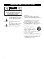
■ Explanation of Graphical Symbols
The lightning flash with arrowhead symbol,
within an equilateral triangle, is intended to
alert you to the presence of uninsulated
“dangerous voltage” within the product’s
enclosure that may be of sufficient magnitude
to constitute a risk of electric shock to
persons.
The exclamation point within an equilateral
triangle is intended to alert you to the
presence of important operating and
maintenance (servicing) instructions in the
literature accompanying the appliance.
1 Read these instructions.
2 Keep these instructions.
3 Heed all warnings.
4 Follow all instructions.
5 Do not use this apparatus near water.
6 Clean only with dry cloth.
7 Do not block any ventilation openings. Install in accordance
with the manufacturer’s instructions.
8 Do not install near any heat sources such as radiators, heat
registers, stoves, or other apparatus (including amplifiers)
that produce heat.
9 Do not defeat the safety purpose of the polarized or
grounding-type plug. A polarized plug has two blades with
one wider than the other. A grounding type plug has two
blades and a third grounding prong. The wide
blade or the third prong are provided for your safety. If the
provided plug does not fit into your outlet, consult an
electrician for replacement of the obsolete outlet.
10 Protect the power supply cable from being walked on or
pinched particularly at plugs, convenience receptacles, and
the point where they exit from the apparatus.
11 Only use attachments/accessories specified by the
manufacturer.
12 Use only with the cart, stand, tripod,
bracket, or table specified by the
manufacturer, or sold with the apparatus.
When a cart is used, use caution when
moving the cart/apparatus combination to
avoid injury from tip-over.
13 Unplug this apparatus during lightning storms or when
unused for long periods of time.
14 Refer all servicing to qualified service personnel. Servicing
is required when the apparatus has been damaged in any way,
such as power-supply cord or plug is damaged, liquid has
been spilled or objects have fallen into the apparatus, the
apparatus has been exposed to rain or moisture, does not
operate normally, or has been dropped.
IMPORTANT SAFETY INSTRUCTIONS
CAUTION: TO REDUCE THE RISK OF
ELECTRIC SHOCK, DO NOT REMOVE
COVER (OR BACK). NO USER-SERVICEABLE
PARTS INSIDE. REFER SERVICING TO
QUALIFIED SERVICE PERSONNEL.
RISK OF ELECTRIC SHOCK
DO NOT OPEN
C
AU
T
I
O
N

IMPORTANT SAFETY INSTRUCTIONS
ii
FCC INFORMATION (for US customers)
1. IMPORTANT NOTICE: DO NOT MODIFY THIS
UNIT!
This product, when installed as indicated in the instructions
contained in this manual, meets FCC requirements.
Modifications not expressly approved by YAMAHA may
void your authority, granted by the FCC, to use the product.
2. IMPORTANT:
When connecting this product to accessories and/or another
product use only high quality shielded cables. Cable/s
supplied with this product MUST be used. Follow all
installation instructions. Failure to follow instructions could
void your FCC authorization to use this product in the USA.
3. NOTE:
This product has been tested and found to comply with the
requirements listed in FCC Regulations, Part 15 for Class
“B” digital devices. Compliance with these requirements
provides a reasonable level of assurance that your use of
this product in a residential environment will not result in
harmful interference with other electronic devices.
This equipment generates/uses radio frequencies and, if not
installed and used according to the instructions found in the
users manual, may cause interference harmful to the
operation of other electronic devices.
Compliance with FCC regulations does not guarantee that
interference will not occur in all installations. If this product
is found to be the source of interference, which can be
determined by turning the unit “OFF” and “ON”, please try
to eliminate the problem by using one of the following
measures:
Relocate either this product or the device that is being
affected by the interference.
Utilize power outlets that are on different branch (circuit
breaker or fuse) circuits or install AC line filter/s.
In the case of radio or TV interference, relocate/reorient the
antenna. If the antenna lead-in is 300 ohm ribbon lead,
change the lead-in to coaxial type cable.
If these corrective measures do not produce satisfactory
results, please contact the local retailer authorized to
distribute this type of product. If you can not locate the
appropriate retailer, please contact YAMAHA Electronics
Corp., U.S.A. 6660 Orangethorpe Ave, Buena Park, CA
90620.
The above statements apply ONLY to those products
distributed by YAMAHA Corporation of America or its
subsidiaries.
We Want You Listening For A Lifetime
YAMAHA and the Electronic Industries Association’s Consumer Electronics Group want you to get the most out of
your equipment by playing it at a safe level. One that lets the sound come through loud and clear without annoying
blaring or distortion – and, most importantly, without affecting your sensitive hearing.
Since hearing damage from loud sounds is often undetectable until it is too late, YAMAHA and the Electronic Industries
Association’s Consumer Electronics Group recommend you to avoid prolonged exposure from excessive volume levels.

CAUTION: READ THIS BEFORE OPERATING THIS UNIT.
iii
1 To assure the finest performance, please read this manual
carefully. Keep it in a safe place for future reference.
2 Install this sound system in a well ventilated, cool, dry, clean
place with at least 5 cm of space above (or below) this unit –
away from direct sunlight, heat sources, vibration, dust, moisture,
and/or cold.
3 Locate this unit away from other electrical appliances, motors, or
transformers to avoid humming sounds.
4 Do not expose this unit to sudden temperature changes from cold
to hot, and do not locate this unit in an environment with high
humidity (i.e. a room with a humidifier) to prevent condensation
inside this unit, which may cause an electrical shock, fire,
damage to this unit, and/or personal injury.
5 Avoid installing this unit where foreign object may fall onto this
unit and/or this unit may be exposed to liquid dripping or
splashing. On the top of this unit, do not place:
– Other components, as they may cause damage and/or
discoloration on the surface of this unit.
– Burning objects (i.e. candles), as they may cause fire, damage
to this unit, and/or personal injury.
– Containers with liquid in them, as they may fall and liquid
may cause electrical shock to the user and/or damage to this
unit.
6 Do not cover this unit with a newspaper, tablecloth, curtain, etc.
in order not to obstruct heat radiation. If the temperature inside
this unit rises, it may cause fire, damage to this unit, and/or
personal injury.
7 Do not plug in this unit to a wall outlet until all connections are
complete.
8 Do not operate this unit upside-down. It may overheat, possibly
causing damage.
9 Do not use force on switches, knobs and/or cords.
10 When disconnecting the power supply cable from the wall outlet,
grasp the plug; do not pull the cable.
11 Do not clean this unit with chemical solvents; this might damage
the finish. Use a clean, dry cloth.
12 Only voltage specified on this unit must be used. Using this unit
with a higher voltage than specified is dangerous and may cause
fire, damage to this unit, and/or personal injury. YAMAHA will
not be held responsible for any damage resulting from use of this
unit with a voltage other than specified.
13 Do not attempt to modify or fix this unit. Contact qualified
YAMAHA service personnel when any service is needed.
The cabinet should never be opened for any reasons.
14 When not planning to use this unit for long periods of time (i.e.
vacation), disconnect the AC power plug from the wall outlet.
15 Be sure to read the “TROUBLESHOOTING” section on
common operating errors before concluding that this unit is
faulty.
16 Before moving this unit, press STANDBY/ON to set this unit in
standby mode, and disconnect the AC power plug from the wall
outlet.
17 Condensation will form when the surrounding temperature
changes suddenly. Disconnect the power supply cable from the
outlet, then leave the unit alone.
18 When using the unit for a long time, the unit may become warm.
Turn the power off, then leave the unit alone for cooling.
19 Install this unit near the wall outlet and where the AC power plug
can be reached easily.
CAUTION: READ THIS BEFORE OPERATING THIS UNIT.
WARNING
TO REDUCE THE RISK OF FIRE OR ELECTRIC SHOCK,
DO NOT EXPOSE THIS UNIT TO RAIN OR MOISTURE.
WARNING
THE POWER SUPPLY CABLE OF THIS UNIT MUST BE
CONNECTED TO THE MAIN SOCKET OUTLET VIA A
PROTECTIVE EARTHING CONNECTION.
This unit is not disconnected from the AC power source as long
as it is connected to the AC wall outlet, even if this unit itself is
turned off. This state is called the standby mode. In this state,
this unit is designed to consume a very small quantity of power.
FOR CANADIAN CUSTOMERS
To prevent electric shock, match wide blade of plug to wide slot
and fully insert.
This Class B digital apparatus complies with Canadian ICES-003.
IMPORTANT
Please record the serial number of this unit in the space below.
MODEL:
Serial No.:
The serial number is located on the rear of the unit. Retain this
Owner’s Manual in a safe place for future reference.
FOR U.K. CUSTOMERS
If the socket outlets in the home are not suitable for the plug
supplied with this appliance, it should be cut off and an
appropriate 3 pin plug fitted. For details, refer to the
instructions described below. Note that the plug severed from
the mains lead must be destroyed, as a plug with bared
flexible cord is hazardous if engaged in a live socket outlet.
IMPORTANT
THE WIRES IN MAINS LEAD ARE COLOURED IN
ACCORDANCE WITH THE FOLLOWING CODE:
Blue: NEUTRAL
Brown: LIVE
As the colours of the wires in the mains lead of this apparatus
may not correspond with the coloured markings identifying
the terminals in your plug, proceed as follows:
The wire which is coloured BLUE must be connected to the
terminal which is marked with the letter N or coloured
BLACK. The wire which is coloured BROWN must be
connected to the terminal which is marked with the letter L or
coloured RED. Make sure that neither core is connected to the
earth terminal of the three pin plug.
CAUTION
Danger of explosion if battery is incorrectly replaced. Replace
only with the same or equivalent type.
CAUTION
Use of controls or adjustments or performance of procedures
other than those specified herein may result in hazardous radi-
ation exposure.

1
PREPARATIONINTRODUCTION
BASIC
OPERATION
ADVANCED
OPERATION
ADDITIONAL
INFORMATION
SETUP
OVERVIEW ........................................................... 2
FEATURES............................................................. 3
USING THIS MANUAL ........................................ 4
SUPPLIED ACCESSORIES ................................. 5
CONTROLS AND FUNCTIONS ......................... 6
Front panel ................................................................. 6
Front panel display .................................................... 7
Rear panel .................................................................. 8
Remote control........................................................... 9
INSTALLATION ................................................. 11
Before installing this unit......................................... 11
Installing this unit .................................................... 11
CONNECTIONS .................................................. 15
Connecting a TV...................................................... 16
Connecting a DVD player/recorder ......................... 17
Connecting a VCR................................................... 18
Connecting a digital satellite tuner
or a cable TV tuner .............................................. 19
Connecting a digital airwave tuner .......................... 20
Connecting other external components ................... 21
Connecting a subwoofer .......................................... 22
Affixing the optical cable ........................................ 23
Connecting the power supply cable ......................... 23
About the RS-232C/REMOTE IN/
IR-OUT terminals................................................ 23
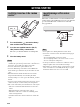
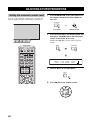
GETTING STARTED.......................................... 24
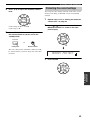
Installing batteries in the remote control ................. 24
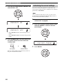
Operation range of the remote control..................... 24
Using the remote control ......................................... 25
Turning on the power............................................... 25
USING SET MENU.............................................. 26
Displaying the OSD ................................................. 26
The flow chart of SET MENU................................. 27
AUTO SETUP....................................................... 28
The flow chart of AUTO SETUP ............................ 28
Installing the optimizer microphone ........................ 29
Using AUTO SETUP .............................................. 31
USING THE SYSTEM MEMORY .................... 36
Saving settings ......................................................... 36
Loading settings....................................................... 37
PLAYBACK ..........................................................39
Selecting the input source........................................ 39
Playing back sources ............................................... 40
Adjusting the volume............................................... 40
Muting the sound ..................................................... 41
BEAM MODE .......................................................42
5 beam mode............................................................ 43
Stereo plus 3 beam mode ......................................... 43
3 beam mode............................................................ 44
Stereo mode ............................................................. 44
Target mode ............................................................. 45
ENJOYING SURROUND SOUND .....................46
Enjoying 2-channel sources
in surround sound ................................................ 47
Enjoying TV in surround sound .............................. 48
Adjusting surround mode parameters ...................... 49
USING SOUND FIELD PROGRAMS................51
What is a sound field? ............................................. 51
Sound field program descriptions ............................ 52
Turning on CINEMA DSP programs ...................... 53
Turning off CINEMA DSP programs ..................... 55
Adjusting CINEMA DSP levels .............................. 55
USING THE VOLUME MODE ..........................56
USING TruBass.....................................................58
USING THE SLEEP TIMER ..............................60
Setting the sleep timer ............................................. 60
Canceling the sleep timer ........................................ 61
BASIC SETUP.......................................................62
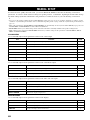
MANUAL SETUP .................................................68
Using MANUAL SETUP........................................ 69
BEAM MENU ......................................................... 70
SOUND MENU....................................................... 74
INPUT MENU......................................................... 77
DISPLAY MENU.................................................... 79
ADJUSTING SYSTEM PARAMETERS ...........80
Setting the maximum volume level ......................... 80
Protecting the current settings ................................. 81
Initializing the current settings ................................ 82
Adjusting the audio balance .................................... 83
SELECTING THE INPUT MODE .....................86
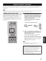
REMOTE CONTROL FEATURES ...................87
Setting remote control codes ................................... 87
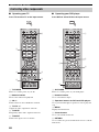
Controlling other components ................................. 88
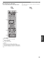
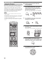
Using the TV macro ................................................ 90
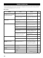
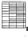
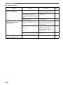
TROUBLESHOOTING .......................................92
GLOSSARY...........................................................95
Audio formats .......................................................... 95
Audio information ................................................... 95
INDEX....................................................................96
SPECIFICATIONS...............................................97
CONTENTS
INTRODUCTION
PREPARATION
SETUP
BASIC OPERATION
ADVANCED OPERATION
ADDITIONAL INFORMATION

OVERVIEW
2
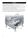
It is generally accepted that in order to fully enjoy the benefits of surround sound at home, you must endure the agony of
wiring and installing a great number of speakers in the hope that your listening room will give you the same kind of
surround sound experience as your local movie theater.
YAMAHA YSP-1000 Digital Sound Projector challenges this preconception that complicated speaker setup and
troublesome wiring go hand-in-hand with the enjoyment of multi-channel surround sound.
This slimline unit does away with the need for complicated wiring and installation worries, leaving you with a unit that is
not only easy to set up, but which is also capable of reproducing the kind of powerful surround sound you have been
waiting for from its built-in subwoofers (2) and individual speakers (40).
You can fine-tune the parameters of this unit to adjust the delay time for separate sound beams, resulting in highly
directional sound that comes in on the listening position from all directions.
The YSP-1000 projects sound beams containing surround sound information for the front right (R), front left (L),
surround right (SR) and surround left (SL) speaker positions, which are reflected off the walls of your listening room
before reaching the actual listening position. With the addition of center (C) sound beams, this Digital Sound Projector
creates true-to-life 5.1 channel surround sound that makes you feel as if there are actual speakers around the room.
Sit back and enjoy the real sound experience of this simple, yet stylish Digital Sound Projector.
OVERVIEW
SL
SR
R
L
C
Listening position
Imaginary
surround left
speaker
Imaginary
surround right
speaker
Imaginary
front left
speaker
Imaginary
front right
speaker
Imaginary
center
speaker

FEATURES
3
INTRODUCTION
Digital Sound Projector
This unit employs the digital sound projector technology
that allows one slim unit to control and steer multiple
channels of sound to generate full, physical 5.1 channel
surround sound, thus eliminating the need for satellite
loudspeakers and cabling normally associated with
conventional surround sound systems. This unit is also
equipped with the following 5 beam modes so that you can
choose the behavior of sound beams that best matches
your listening environment.
◆ 5 beam mode
◆ ST(STEREO)+3 beam mode
◆ 3 beam mode
◆ Stereo mode
◆ Target mode
Cinema DSP Digital
This unit employs the Cinema DSP Digital technology
developed by YAMAHA Electronics Corp. so that you can
experience movies at home with all the dramatic sound
impact that the director intended to convey.
OSD (on-screen display)
This unit employs the OSD which is basically a
superimposed screen image displayed on your video
monitor. The OSD is used to display the system
information or adjust settings for the system parameters.
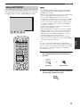
Versatile Remote Control
The supplied remote control come with preset remote
control codes to be used to control the DVD player, VCR,
cable TV tuner and digital satellite tuner connected to this
unit. In addition, the remote control is equipped with the
macro capability so that you can perform a series of
operations with the press of a single button.
AUTO SETUP
This unit employs the automatic sound beam optimization
using the YAMAHA Parametric Room Acoustic
Optimizer (YPAO) technology with the aid of the supplied
optimizer microphone so that you can avoid troublesome
listening-based speaker setup and achieve highly accurate
sound beam adjustments that best match your listening
environment.
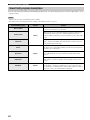
Compatibility with the Newest Technologies
This unit employs decoders compatible with Dolby
Digital, DTS (Digital Theater Systems), Dolby Pro Logic,
Dolby Pro Logic II and DTS Neo:6.
◆ Dolby Digital
This is the standard audio signal format used on DVDs and
other purely digital media. This surround technology deliver
high-quality digital audio for up to 5.1 discrete channels to
produce a directional and more realistic effect.
◆ DTS (Digital Theater Systems)
This is an audio signal format used on DVDs and other purely
digital media. This surround technology deliver high-quality
digital audio for up to 5.1 discrete channels to produce a
directional and more realistic effect.
◆ Dolby Pro Logic
This sophisticated, matrix decoding technology up-converts
any 2 channel source audio to a surround sound playback.
◆ Dolby Pro Logic II
This is fundamentally a redesigned version of Dolby Pro
Logic that employs 2 stereo surround channels, a subwoofer
and a greatly enhanced steering logic. As a result, this
improved technology provides an exceptionally stable sound
field that simulates 5.1 to a much greater degree than the
original Dolby Pro Logic. In addition, Dolby Pro Logic II
features Movie, Music and Game modes specifically designed
for movies, music and games respectively.
◆ DTS Neo:6
This technology decodes the conventional 2 channel sources
for maximum 6 channel playback, enabling playback with the
full-range channels with higher separation. This unit is
equipped with the 5 channel playback mode. Music mode and
Cinema mode are available to play back music and movie
sources respectively.
The “ ” logo and “Cinema DSP” are registered
trademarks of YAMAHA Corporation.
Manufactured under license from Dolby Laboratories.
“Dolby”, “Pro Logic”, and the double-D symbol are trademarks
of Dolby Laboratories.
“DTS”, and “Neo:6” are trademarks of Digital Theater Systems,
Inc.
Manufactured under license from 1 Ltd. Worldwide patents
applied for.
The ‘ ’ logo and ‘Digital Sound Projector
™
’ are trademarks
of 1 Ltd.
TruBass, SRS and the “ ” symbol are registered trademarks
of SRS Labs, Inc. TruBass technology is incorporated under
license from SRS Labs, Inc.
FEATURES

USING THIS MANUAL
4
• This manual describes how to connect and operate this unit. For details regarding the operation of external components, refer to the
supplied owner’s manual for the component.
• Some operations can be performed by using either the buttons on the main unit or on the remote control. In such cases, the operation is
described using remote control operation.
• y indicates a tip for your operation.
• This manual is printed prior to production. Design and specifications are subject to change in part as a result of improvements, etc. In
case of differences between the manual and product, the product has priority.
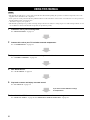
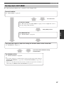
1 Install this unit in your listening room.
See “INSTALLATION” on page 11.
2 Connect this unit to your TV and other external components.
See “CONNECTIONS” on page 15.
3 Prepare the remote control and turn on the power of this unit.
See “GETTING STARTED” on page 24.
4 Run AUTO SETUP.
See “AUTO SETUP” on page 28.
5 Play back a source and enjoy surround sound.
See “PLAYBACK” on page 39.
6 Run MANUAL SETUP and set remote control codes to fine-tune settings.
See “MANUAL SETUP” on page 68 and “REMOTE CONTROL FEATURES” on page 87.
USING THIS MANUAL
Notes
If you want to make additional settings
and adjustments

SUPPLIED ACCESSORIES
5
INTRODUCTION
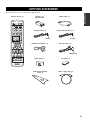
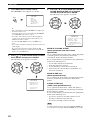
Check that you have received all of the following parts.
SUPPLIED ACCESSORIES
TV
POWER
2
1
STEREO
SLEEP
CH LEVEL MENU
RETURN
TEST
TV VOL
VOLUME
MUTE TV INPUT TV MUTE
ENTER
SURROUND
OFF
CODE SET
SPORTS
AV
POWER
STANDBY/ON
3
4
56
789
0
+10
5BEAM
ST+3BEAM
3BEAM
TARGET
MUSIC MOVIE VOL MODE
INPUTMODE
MACROINPUT2INPUT1
TV
STBVCRDVD
AUX
YSP
CINEMA DSP
CH
TV
Remote control (×1)
Batteries (×2)
(AA, R6, UM-3)
Video pin cable (×1)
Optimizer microphone (×1)
Fastener (×4)
Audio pin cable (×1)
Digital audio pin cable (×1)
Optical cable (×1)
Cable clamp (×1)
Cardboard microphone
stand (×1)
(Orange)
(White/Red)
(Yellow)
Power supply cable (×1)

CONTROLS AND FUNCTIONS
6
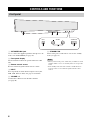
1 OPTIMIZER MIC jack
Use to connect the supplied optimizer microphone to be
used to run AUTO SETUP (see page 28).
2 Front panel display
Shows information about the operational status of this
unit.
3 Remote control sensor
Receives infrared signals from the remote control.
4 INPUT
Press repeatedly to switch between input sources (TV,
STB, VCR, DVD or AUX). See page 39 for details.
5 VOLUME –/+
Controls the volume level of all audio channels
(see page 40).
6 STANDBY/ON
Turns on the power of this unit or sets it to the standby
mode (see page 25).
• When you turn on the power of this unit, you will hear a click
and there will be a 4 to 5-second delay before it can reproduce
sound.
• In the standby mode, this unit consumes a small amount of
power in order to receive infrared-signals from the remote
control.
CONTROLS AND FUNCTIONS
Front panel
2
3
4
1
5
6
STANDBY/ONVOLUME
+
INPUT
Notes

CONTROLS AND FUNCTIONS
7
INTRODUCTION
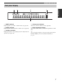
1 NIGHT indicator
Lights up when you select a volume mode (see page 56).
2 SLEEP indicator
Lights up when the sleep timer is turned on (see page 60).
3 Decoder indicators
Light up when the corresponding decoder of this unit is in
operation (see page 46).
4 Volume level indicator
Shows the current volume level (see page 40).
5 Multi-information display
Shows information when you adjust the parameters of this
unit.
y
You can adjust the brightness of the front panel display using the
DISPLAY MENU parameters in MANUAL SETUP (see
page 79).
Front panel display
NIGHT SLEEP PCM PL
m
ft
mS
dB
VOLDIGITAL
5
412 3

CONTROLS AND FUNCTIONS
8
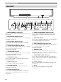
1 RS-232C/REMOTE IN terminals
These are control expansion terminals for factory use only
(see page 23).
2 DVD COAXIAL DIGITAL IN jack
Use to connect a DVD player/recorder via a coaxial digital
connection (see page 17).
3 AUX OPTICAL DIGITAL IN jack
Use to connect an external component via an optical
digital connection (see page 21).
4 TV/STB OPTICAL DIGITAL IN jack
Use to connect a TV, a digital satellite tuner or a cable TV
tuner via an optical digital connection
(see page 16, 19 and 20).
5 TV/STB AUDIO IN jacks
Use to connect a TV, a digital satellite tuner or a cable TV
tuner via an analog audio connection
(see page 16, 19 and 20).
6 VCR AUDIO IN jacks
Use to connect a VCR via an analog audio connection
(see pages 17 and 18).
7 SUBWOOFER jack
Use to connect a subwoofer (see page 22).
8 VCR VIDEO IN jack
Use to connect a VCR via a composite analog video
connection (see page 18).
9 DVD/AUX VIDEO IN jack
Use to connect a DVD player/recorder or an external
component via a composite analog video connection
(see page 17).
0 DVD/AUX COMPONENT VIDEO IN jacks
Use to connect a DVD player/recorder or an external
component via a component analog video connection
(see page 17).
A STB VIDEO IN jack
Use to connect a digital satellite tuner or a cable TV tuner
via a composite analog video connection
(see pages 19 and 20).
B STB COMPONENT VIDEO IN jacks
Use to connect a digital satellite tuner or a cable TV tuner
via a component analog video connection
(see pages 19 and 20).
C VIDEO OUT jack
Use to connect to the video input jack of your TV via a
composite analog video connection to display the OSD of
this unit (see page 16).
D COMPONENT VIDEO OUT jacks
Use to connect to the video input jacks of your TV via a
component analog video connection to display the OSD of
this unit (see page 16).
E IR-OUT terminal
This is a control expansion terminal for factory use only
(see page 23).
F AC IN
Use to connect the supplied power supply cable
(see page 23).
Rear panel
REMOTE IN
RS-232C
VIDEO OUTVIDEO INAUDIO IN
OPTICAL
DIGITAL IN
VCR
VCR STB
AUX
DVD/AUX
DVD
COAXIAL
TV/STB
TV/STB
COMPONENT COMPONENT COMPONENT
SUBWOOFER
123 654798CA
DB0
EF

CONTROLS AND FUNCTIONS
9
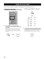
INTRODUCTION
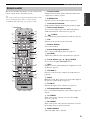
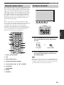
This section describes the function of each control on the
remote control used to control this system.
y
You can also control other components using the remote control
once you set the appropriate remote control codes. See
“Controlling other components” on page 88 for details.
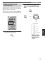
1 Infrared window
Outputs infrared control signals. Aim this window at the
component you want to operate.
2 STANDBY/ON
Sets this system to the standby mode (see page 25).
3 Transmission indicator
Lights up when infrared control signals are being output.
4 Input selector buttons
Use to select an input source (TV, STB, VCR, DVD or
AUX) and change the control area (see page 39).
5 TruBass
Use to effectively reproduce the bass sound (see page 58).
6 YSP
Switches to the operation mode of this unit.
7 Numeric buttons
Use to enter numbers.
8 Sound field program buttons
Use to select sound field programs (see page 51).
9 CH LEVEL
Adjusts the volume level of each channel (see page 84).
0 Cursor buttons / / / , ENTER
Use to select and adjust SET MENU items.
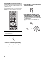
A TEST
Outputs a test tone when adjusting the output level of each
speaker (see page 83).
B VOLUME +/–
Increases or decreases the volume level of this unit (see
page 40).
C MUTE
Mutes the sound. Press again to restore the audio output to
the previous volume level (see page 41).
D TV INPUT
Switches the input source of the TV (see page 88).
E DVD player/VCR control buttons
Use to control the DVD player of the VCR (see pages 88
and 89).
F TV POWER
Turns on the power of the TV or sets it to the standby
mode (see page 88).
G AV POWER
Turns on the power of the selected component or sets it to
the standby mode (see pages 88 and 89).
H INPUT1/INPUT2
Selects the input source of the TV.
Remote control
TV
POWER
2
1
STEREO
SLEEP
CH LEVEL MENU
RETURN
TEST
TV VOL
VOLUME
MUTE TV INPUT TV MUTE
ENTER
SURROUND
OFF
CODE SET
SPORTS
AV
POWER
STANDBY/ON
3
4
56
789
0
+10
5BEAM
ST+3BEAM
3BEAM
MUSIC MOVIE VOL MODE
INPUTMODE
MACROINPUT2INPUT1
TV
STBVCRDVD
AUX
YSP
CINEMA DSP
CH
TARGET
TV
1
2
4
6
7
9
0
A
E
I
J
N
K
O
P
Q
S
5
3
H
M
8
L
D
C
R
B
G
F

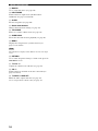
CONTROLS AND FUNCTIONS
10
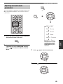
I MACRO
Use to set the TV macro (see page 90).
J INPUTMODE
Switches between input modes (AUTO, DTS or
ANALOG). See page 39 for details.
K SLEEP
Sets the sleep timer (see page 60).
L Beam mode buttons
Change the beam mode settings (see page 42).
M VOL MODE
Turns on or off the volume modes (see page 56).
N SURROUND
Selects the surround mode for playback (see page 46).
O MENU
Displays the setup menu on your TV monitor (see
pages 31, 62 and 69).
The DVD menu is displayed when DVD is selected as the input
source.
P RETURN
Use to select sleep timer settings or return to the previous
SET MENU screen.
Q TV VOL +/–
Adjusts the volume level of the TV (see page 88).
R CH +/–
Switches between channels of the TV or the VCR (see
pages 88 and 89).
S TV MUTE, CODE SET
Mutes the audio output of the TV (see page 88).
Use to set up remote control codes (see page 87).
Note

INSTALLATION
11
PREPARATION
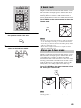
This section describes a suitable installation location to install the unit using a metal wall bracket, a rack or a stand.
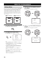
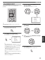
This unit creates surround sound by reflecting projected
sound beams off the walls of your listening room. The
surround sound effects produced by this unit may not be
sufficient when the unit is installed in the following
locations.
• Rooms with surfaces inadequate for reflecting sound
beams
• Rooms with acoustically absorbent surfaces
• Rooms with measurements outside the following range
W (3 to 7 m) x H (2 to 3.5 m) x D (3 to 7 m)
• Rooms with less than 2 m from the listening position to
the speaker positions
• Rooms where objects such as furniture are likely to
obstruct the path of sound beams
• Rooms where the listening position is close to the walls
• Rooms where the listening position is not in front of
this unit
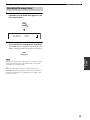
Make sure you leave an adequate amount of ventilation
space so that heat can escape. Make at least 5 cm of space
above or below this unit.
• This unit weighs 13.0 kg. Be sure to install this unit where it
will not fall subject to vibrations, such as from an earthquake,
and where it is out of the reach of children.
• When using a cathode-ray tube (CRT) TV, do not install this
unit directly above your TV.
• This unit is shielded against magnetic rays. However, if the
picture on your TV screen becomes blurred or distorted, we
recommend moving the speakers away from your TV.
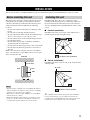
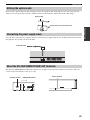
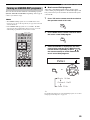
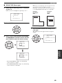
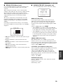
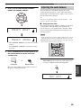
Install this unit where there are no obstacles such as
furniture obstructing the path of sound beams. Otherwise,
the desired surround sound effects may not be achieved.
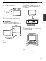
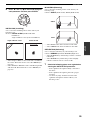
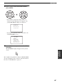
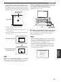
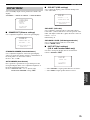
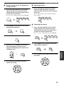
You may install this unit in parallel with the wall or in the
corner.
■ Parallel installation
Install this unit in the exact center of the wall when it is
measured from the left and right corners.
■ Corner installation
Install this unit in the corner at a 40º to 50º angle from the
adjacent walls.
y
The availability of the beam mode depends on the installation
location of this unit (see page 42). All five beam modes are
available for the parallel installation whereas the 3 beam and 5
beam modes are not available for the corner installation.
INSTALLATION
Before installing this unit
Notes
5 cm or more
RearFront
Side view
Side
Installing this unit
An object, such as furniture
40° to 50°
An object, such as furniture

12
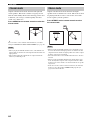
INSTALLATION
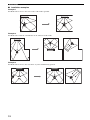
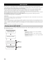
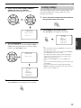
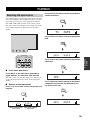
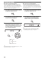
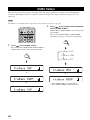
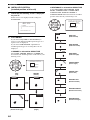
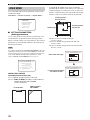
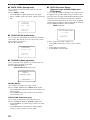
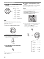
■ Installation examples
Example 1
Install this unit as close to the exact center of the wall as possible.
Example 2
Install this unit so that the sound beams can be reflected off the walls.
Example 3
Install this unit as close to the exact front of your normal listening position.

13
INSTALLATION
PREPARATION
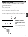
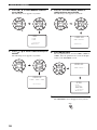
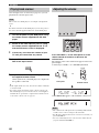
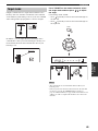
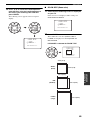
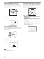
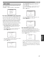
■ Using a metal wall bracket
You can use the optional metal wall bracket to mount this
unit on the wall in your listening room.
y
Refer to the instructions supplied with the metal bracket for
details on how to attach the metal bracket to the wall or how to
attach this unit to the metal bracket.
■ Using a stand
You can mount your TV on the stand placed on a
commercially available rack to install this unit under your
TV.
y
Refer to the instructions supplied with the stand for details on
how to install the stand or how to mount this unit and the TV on
the stand.
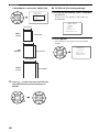
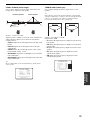
■ Using a TV stand
You can use the optional TV stand to install this unit. For
detailed information on installing this unit using a TV
stand, refer to the installation manual supplied with the
optional TV stand.
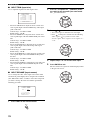
■ Using a rack
You can install this unit either above or under your TV in a
commercially available rack.
Make sure that the rack is large enough to allow adequate
ventilation space around this unit (see page 11) and that it is
strong enough to support the weight of both this unit and your TV.
This unit
TV
Metal wall bracket
TV
This unit
Stand
Note
This unit
TV
When this unit is installed above your TV
When this unit is installed under your TV

14
INSTALLATION
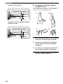
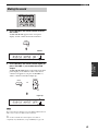
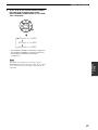
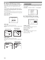
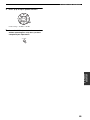
■ Affixing this unit
Peel off the film from each of the four supplied fasteners
and then secure them to the bottom four corners of this
unit and the top of the rack, etc.
• Do not install this unit on top of a slanted surface. This unit may
fall over and cause injury.
• Make sure you wipe the surface of the rack, etc. before securing
the fasteners. Applying the tape to a dirty or wet surface will
weaken the sticking power of the tape, and this unit may fall as
a result.
Notes
2
1
This unit
Peel off
the film
Fasteners
Peel off
the pad
on the
bottom

CONNECTIONS
15
PREPARATION
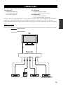
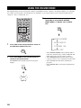
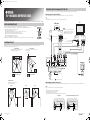
This unit is equipped with the following types of audio/video input/output jacks:
For audio input
• 2 optical digital input jacks
• 1 coaxial digital input jack
• 2 sets of analog input jacks
For video input
• 3 composite analog input jacks
• 2 sets of component analog input jacks
For video output
• 1 composite analog output jack
• 1 set of component analog output jacks
Use these audio/video input/output jacks to connect external components such as your TV, DVD player, VCR, digital
satellite tuner, cable TV tuner and game console. Further, by connecting a subwoofer to this unit, you can enjoy
reinforced low bass sounds. For details on how to connect various types of external components to this unit, see pages 16
to 22.
Do not connect this unit or other components to the main power until all connections between components are complete.
CONNECTIONS
CAUTION
Audio connection
Video connection
DVD player Subwoofer
This unit
VCR Digital satellite tuner, cable TV
tuner or game console
TV

16
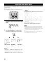
CONNECTIONS
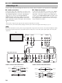
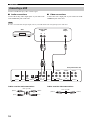
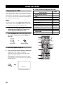
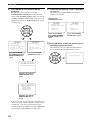
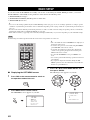
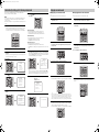
Connect a TV to this unit and display the OSD for easy viewing when you adjust the system parameters in SET MENU.
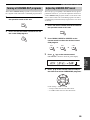
■ Audio connections
Connect the analog audio output jacks of your TV to the
TV/STB AUDIO IN jacks of this unit. If your TV has an
optical digital output jack, connect the optical digital
output jack of your TV to the TV/STB OPTICAL
DIGITAL IN jack of this unit in addition to the analog
audio connection. Once the digital audio connection is
made, digital audio signals can be input to this unit during
digital broadcasting.
■ Video connections
Connect the video input jacks of your TV to the VIDEO
OUT jack of this unit. If your TV has component video
input jacks, connect the component video input jacks of
your TV to the COMPONENT VIDEO OUT jacks of this
unit in addition to the composite video connection. Once
the component video connection is made, you can enjoy
images with better resolution.
y
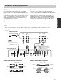
• The circuits of composite and component video signals are independent of each other.
• To prevent the optical cable from being unplugged, affix the optical cable in the supplied cable clamp (see page 23).
If you connect this unit to the analog audio and optical digital audio output jacks at the same time as shown in the left illustration below,
the digital audio signals output at the optical digital output jack take priority over the analog audio signals output at the analog audio
output jacks.
Cables used for audio connections Cables used for video connections
Connecting a TV
Note
REMOTE IN
RS-232C
VIDEO OUTVIDEO INAUDIO IN
OPTICAL
DIGITAL IN
VCR
VCR STB
AUX
DVD/AUX
DVD
COAXIAL
TV/STB
TV/STB
SUBWOOFER
COMPONENT COMPONENT COMPONENT
Rear panel of this unit
TV
Optical digital
output
Analog audio
output
RL
Video
input
Component
video input
Optical cable (supplied)
Audio pin cable (supplied)
(White)
(Red)
(White)
(Red)
Video pin cable (supplied)
(Yellow)(Yellow)
Component video pin cable
(Green)
(Blue)
(Red)
(Green)
(Blue)
(Red)
Pagina se încarcă...
Pagina se încarcă...
Pagina se încarcă...
Pagina se încarcă...
Pagina se încarcă...
Pagina se încarcă...
Pagina se încarcă...
Pagina se încarcă...
Pagina se încarcă...
Pagina se încarcă...
Pagina se încarcă...
Pagina se încarcă...
Pagina se încarcă...
Pagina se încarcă...
Pagina se încarcă...
Pagina se încarcă...
Pagina se încarcă...
Pagina se încarcă...
Pagina se încarcă...
Pagina se încarcă...
Pagina se încarcă...
Pagina se încarcă...
Pagina se încarcă...
Pagina se încarcă...
Pagina se încarcă...
Pagina se încarcă...
Pagina se încarcă...
Pagina se încarcă...
Pagina se încarcă...
Pagina se încarcă...
Pagina se încarcă...
Pagina se încarcă...
Pagina se încarcă...
Pagina se încarcă...
Pagina se încarcă...
Pagina se încarcă...
Pagina se încarcă...
Pagina se încarcă...
Pagina se încarcă...
Pagina se încarcă...
Pagina se încarcă...
Pagina se încarcă...
Pagina se încarcă...
Pagina se încarcă...
Pagina se încarcă...
Pagina se încarcă...
Pagina se încarcă...
Pagina se încarcă...
Pagina se încarcă...
Pagina se încarcă...
Pagina se încarcă...
Pagina se încarcă...
Pagina se încarcă...
Pagina se încarcă...
Pagina se încarcă...
Pagina se încarcă...
Pagina se încarcă...
Pagina se încarcă...
Pagina se încarcă...
Pagina se încarcă...
Pagina se încarcă...
Pagina se încarcă...
Pagina se încarcă...
Pagina se încarcă...
Pagina se încarcă...
Pagina se încarcă...
Pagina se încarcă...
Pagina se încarcă...
Pagina se încarcă...
Pagina se încarcă...
Pagina se încarcă...
Pagina se încarcă...
Pagina se încarcă...
Pagina se încarcă...
Pagina se încarcă...
Pagina se încarcă...
Pagina se încarcă...
Pagina se încarcă...
Pagina se încarcă...
Pagina se încarcă...
Pagina se încarcă...
Pagina se încarcă...
Pagina se încarcă...
Pagina se încarcă...
Pagina se încarcă...
Pagina se încarcă...
-
 1
1
-
 2
2
-
 3
3
-
 4
4
-
 5
5
-
 6
6
-
 7
7
-
 8
8
-
 9
9
-
 10
10
-
 11
11
-
 12
12
-
 13
13
-
 14
14
-
 15
15
-
 16
16
-
 17
17
-
 18
18
-
 19
19
-
 20
20
-
 21
21
-
 22
22
-
 23
23
-
 24
24
-
 25
25
-
 26
26
-
 27
27
-
 28
28
-
 29
29
-
 30
30
-
 31
31
-
 32
32
-
 33
33
-
 34
34
-
 35
35
-
 36
36
-
 37
37
-
 38
38
-
 39
39
-
 40
40
-
 41
41
-
 42
42
-
 43
43
-
 44
44
-
 45
45
-
 46
46
-
 47
47
-
 48
48
-
 49
49
-
 50
50
-
 51
51
-
 52
52
-
 53
53
-
 54
54
-
 55
55
-
 56
56
-
 57
57
-
 58
58
-
 59
59
-
 60
60
-
 61
61
-
 62
62
-
 63
63
-
 64
64
-
 65
65
-
 66
66
-
 67
67
-
 68
68
-
 69
69
-
 70
70
-
 71
71
-
 72
72
-
 73
73
-
 74
74
-
 75
75
-
 76
76
-
 77
77
-
 78
78
-
 79
79
-
 80
80
-
 81
81
-
 82
82
-
 83
83
-
 84
84
-
 85
85
-
 86
86
-
 87
87
-
 88
88
-
 89
89
-
 90
90
-
 91
91
-
 92
92
-
 93
93
-
 94
94
-
 95
95
-
 96
96
-
 97
97
-
 98
98
-
 99
99
-
 100
100
-
 101
101
-
 102
102
-
 103
103
-
 104
104
-
 105
105
-
 106
106


Yamaha YSP-1000 Manual de utilizare
- Categorie
- Receptor
- Tip
- Manual de utilizare
în alte limbi
- Türkçe: Yamaha YSP-1000 Kullanım kılavuzu
- français: Yamaha YSP-1000 Manuel utilisateur
- čeština: Yamaha YSP-1000 Uživatelský manuál
- русский: Yamaha YSP-1000 Руководство пользователя
- English: Yamaha YSP-1000 User manual
- suomi: Yamaha YSP-1000 Ohjekirja
- polski: Yamaha YSP-1000 Instrukcja obsługi
- Deutsch: Yamaha YSP-1000 Benutzerhandbuch
- italiano: Yamaha YSP-1000 Manuale utente
- español: Yamaha YSP-1000 Manual de usuario
- svenska: Yamaha YSP-1000 Användarmanual
- dansk: Yamaha YSP-1000 Brugermanual
- português: Yamaha YSP-1000 Manual do usuário
- Nederlands: Yamaha YSP-1000 Handleiding
Lucrări înrudite
-
Yamaha YSP-1 Manual de utilizare
-
Yamaha YSP 1100 - Digital Sound Projector Five CH Speaker Manualul proprietarului
-
Yamaha YSP-900 Manualul proprietarului
-
-
-
-
-
Yamaha YSP-3000 Manualul proprietarului
-
-
Yamaha YSP-4000 Manualul proprietarului