Ubiquiti PrismStation AC Ghid de inițiere rapidă
- Categorie
- Antene de rețea
- Tip
- Ghid de inițiere rapidă

Shielded airMAX
®
ac Radio
with airPrism
®
Technology and
Dedicated Wi-Fi Management
Model: PS-5AC
Available from A1 Security Cameras
www.a1securitycameras.com email: [email protected]

Introduction
Thank you for purchasing the Ubiquiti Networks®
PrismStation
™
AC. This Quick Start Guide is designed to guide
you through installation and also includes warrantyterms.
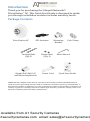
Package Contents
PrismStation AC GPS Antenna Mounting
Bracket
Pole Clamp
Carriage Bolts
(Qty. 2)
Flange Nuts
(Qty. 2)
Allen Wrench
Shielded airMAX
®
ac Radio
with airPrism
®
Technology and
Dedicated Wi-Fi Management
Model: PS-5AC
Gigabit PoE (24V, 1A)
with Mounting Bracket
Power Cord Quick Start Guide
TERMS OF USE: Ubiquiti radio devices must be professionally installed. Shielded Ethernet
cable and earth grounding must be used as conditions of product warranty. TOUGHCable
™
is
designed for outdoor installations. It is the professional installer’s responsibility to follow local
country regulations, including operation within legal frequency channels, output power, and
Dynamic Frequency Selection (DFS) requirements.
Available from A1 Security Cameras
www.a1securitycameras.com email: [email protected]

Installation Requirements
• The PS-5AC must be used with one of the following
horns (not included):
• Prism®AP-5-30
• PrismAP-5-45
• PrismAP-5-60
• PrismAP-5-90
• The GPS Antenna needs to have clear line of sight to thesky
for proper GPS operation.
• 13 mm wrench
• 5 mm hex socket (recommended for the Mounting Bracket)
• Shielded Category 5 (or above) cabling with drain wire
should be used for all wired Ethernet connections and
should be grounded through the AC ground of the PoE.
We recommend that you protect your networks from
harmful outdoor environments and destructive ESD events
with industrial-grade, shielded Ethernet cable from Ubiquiti
Networks. For more details, visit
www.ubnt.com/toughcable
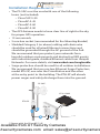
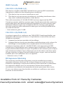
• Surge protection should be used for all outdoor installations.
We recommend that you use two Ethernet Surge Protectors,
model ETH-SP, one near the PrismStation and the other
at the entry point to the building. The ETH-SP will absorb
power surges and safely discharge them into the ground.
To LAN
ETH-SP
ETH-SP
ES-8-150W
PS-5AC*
* Shown with the PrismAP-5-45
Available from A1 Security Cameras
www.a1securitycameras.com email: [email protected]

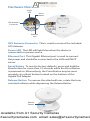
Hardware Overview
Reset
Button
Ethernet
Port
Power
LED
GPS Antenna
Connector
GPS Antenna Connector This is used to connect the included
GPS Antenna.
Power LED The LED will light blue when the device is
connected to a power source.
Ethernet Port This Gigabit Ethernet port is used to connect
the power and should be connected to the LAN and DHCP
server.
Reset Button To reset to factory defaults, press and hold the
Reset button for more than 10 seconds while the PrismStation
is poweredon. Alternatively, the PrismStation may be reset
remotely via a Reset button located on the bottom of the
Gigabit PoE Adapter.
Release Button To remove the attached horn, rotate the horn
counterclockwise while depressing the Release Button.
Release
Button
Available from A1 Security Cameras
www.a1securitycameras.com email: [email protected]

Hardware Installation
These instructions show the PrismAP-5-45; however, the
PrismStation is also compatible with the following horns:
• PrismAP-5-30
• PrismAP-5-60
• PrismAP-5-90
1. To install the horn, insert the PrismAP into the PrismStation
and align the arrow on the horn with the Release Button.
2. Press down on the horn and rotate it clockwise until you
hear a click.
Available from A1 Security Cameras
www.a1securitycameras.com email: [email protected]

Pole-Mounting
1. Attach the Pole Clamp to the Mounting Bracket.
a. Hold the Mounting Bracket with its clamps facing you
and the head of the Tightening Bolt facing upward.
b. Insert the two Carriage Bolts through the holes of the
Mounting Bracket.
c. Slide the hole of the Pole Clamp over one bolt of the
Mounting Bracket.
d. Place one Flange Nut on each bolt.
2. Loosen the Tightening Bolt of the Mounting Bracket and
open the bracket 90°.
Tightening Bolt
Available from A1 Security Cameras
www.a1securitycameras.com email: [email protected]

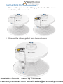
3. Mount the PrismStation on the pole and secure it.
a. Place the Mounting Bracket against the pole.
b. Slide the slot of the Pole Clamp over the adjacent
Carriage Bolt.
c. Tighten the Flange Nuts of the bolts to 25 N ∙ m to
secure the Mounting Bracket to the pole.
25 N ∙ m
4. Insert the PrismStation into the Mounting Bracket, and then
tighten the bolt to lock the PrismStation in place.
Note: The mounting assembly can accommodate a
Ø 25 - 75 mm pole.
Available from A1 Security Cameras
www.a1securitycameras.com email: [email protected]

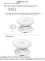
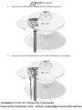
5. Adjust the elevation angle.
a. Loosen the Elevation Screw on the bottom of the
bracket.
Elevation Screw
b. Pivot the PrismStation until the Elevation Indicator
shows the desired elevation angle.
Elevation Indicator
c. Tighten the Elevation Screw to 15 N ∙ m.
Available from A1 Security Cameras
www.a1securitycameras.com email: [email protected]

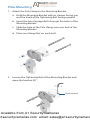
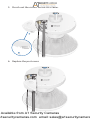
Connecting to Power and GPS
1. Remove the port cover by lifting up the latch of the cover
and sliding the cover out.
2. Remove the rubber gasket from the port cover.
Available from A1 Security Cameras
www.a1securitycameras.com email: [email protected]

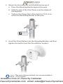
3. Connect an Ethernet cable to the Ethernet port.
4. Connect the GPS Antenna to the GPS Antenna Connector.
Available from A1 Security Cameras
www.a1securitycameras.com email: [email protected]

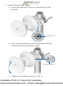
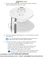
5. Punch out the cutout for the GPS cable.
6. Replace the port cover.
Available from A1 Security Cameras
www.a1securitycameras.com email: [email protected]

7. Fit the rubber gasket over the Ethernet cable, and then
slide the gasket into the port cover.
8. Place the magnetic GPS Antenna on a steel surface near the
PrismStation.
Note: Ensure that the GPS Antenna has clear line of
sight to the sky for proper GPS reception.
9. Connect the power using one of the following options:
• Using the included Gigabit PoE Adapter: Go to
Connecting to the PoE Adapter.
• Using a separate PoE switch: Connect the Ethernet
cable from the PrismStation’s Ethernet port to a
PoE-enabled Ethernet port on the switch.
WARNING: The switch port must comply with the
power specifications listed in the Specifications
section of this Quick Start Guide.
Available from A1 Security Cameras
www.a1securitycameras.com email: [email protected]

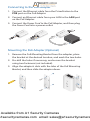
Connecting to the PoE Adapter
1. Connect the Ethernet cable from the PrismStation to the
POE port on the PoEAdapter.
2. Connect an Ethernet cable from your LAN to the LAN port
on the PoE Adapter.
3. Connect the Power Cord to the PoE Adapter, and then plug
the Power Cord into a power outlet.
Mounting the PoE Adapter (Optional)
1. Remove the PoE Mounting Bracket from the adapter, place
the bracket at the desired location, and mark the two holes.
2. Pre-drill the holes if necessary, and secure the bracket
using two fasteners (not included).
3. Align the adapter’s slots with the tabs of the PoE Mounting
Bracket, and then slide the adapterdown.
Available from A1 Security Cameras
www.a1securitycameras.com email: [email protected]

*640-00330-03*
640-00330-03
Accessing airOS via Wi-Fi
Verify connectivity in the airOS® Configuration Interface.
There are two methods, the UNMS
™
and Web Portal. Both
are available for 15 minutes immediately after you power
on the PrismStation. If necessary, you can power cycle the
PrismStation to re-enable its Wi-Fi.
Proceed to the appropriate instructions:
UNMS App
1. Download the UNMS app from the AppStore (iOS) or
Google Play
™
(Android).
2. Connect your device’s Wi-Fi to the PrismStation SSID
named: PS-5AC:<MAC Address>
Note: Ensure that DHCP is enabled on your
Wi-Fiadapter.
3. Launch the app.
4. Tap the PrismStation on the Connections screen.
Available from A1 Security Cameras
www.a1securitycameras.com email: [email protected]

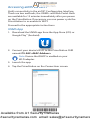
5. Tap Connect on the Login screen.
6. Select your Country and tap Done.
7. Customize your settings as needed.
Available from A1 Security Cameras
www.a1securitycameras.com email: [email protected]

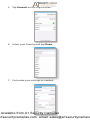
Web Portal
1. Connect your device’s Wi-Fi to the PrismStation SSID
named: PS-5AC:<MAC Address>
Note: Ensure that your Wi-Fi connection has DHCP
enabled.
2. Launch your web browser and go to:
http://setup.ubnt.com
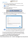
3. Enter ubnt in the Username and Password fields. Select
your Country and Language. You must agree to the Terms of
Use to use the product. Click Login.
Note: The Country setting for U.S. product versions is
restricted to a choice of Canada, Puerto Rico, or the
U.S. to ensure compliance with FCC/IC regulations.
The airOS Configuration Interface will appear, allowing you
to customize your settings as needed. For additional details
on the airOS Configuration Interface, refer to the User Guide
available at www.ubnt.com/download/airmax
Available from A1 Security Cameras
www.a1securitycameras.com email: [email protected]

Installer Compliance Responsibility
Devices must be professionally installed and it is the
professional installer's responsibility to make sure the device is
operated within local country regulatory requirements.
The Antenna and Output Power fields are provided to
the professional installer to assist in meeting regulatory
requirements.
Available from A1 Security Cameras
www.a1securitycameras.com email: [email protected]

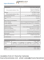
Specifications
PS-5AC
Dimensions
Mounting Hardware Only
155 x 155 x 104 mm
(5.16 x 5.16 x 4.09")
83 x 117 x 69 mm
(3.27 x 4.61 x 2.72")
Weight
Mounting Hardware Only
0.77 kg (1.70 lb)
0.79 kg (1.74 lb)
Networking Interface (1) 10/100/1000 Ethernet Port
RF Connector (1) GPS
LED Power
Max. Power Consumption 10W
Power Supply 24V, 1A Gigabit PoE Adapter (Included)
Power Method 24V Passive PoE (Pairs 4, 5+; 7, 8 Return)
Supported Voltage Range 20 to 26VDC
Wind Loading 31 N @ 200 km/h (7 lbf @ 125 mph)
Wind Survivability 200 km/h (125 mph)
Operating Temperature -40 to 70° C (-40 to 158° F)
Operating Humidity 5 to 95% Noncondensing
Mounting Pole-Mount (Kit Included)
ESD/EMP Protection ± 24kV Contact/Air
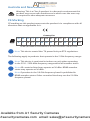
Certications CE, FCC, IC
Operating Frequency (MHz)
Worldwide 5150 - 5875
USA
U-NII-1:
5150 - 5250
U-NII-2A:
5250 - 5350
U-NII-2C:
5470 - 5725
U-NII-3:
5725 - 5850
Management Radio (MHz)
Worldwide 2412 - 2472
USA 2412 - 2462
Available from A1 Security Cameras
www.a1securitycameras.com email: [email protected]

Safety Notices
1. Read, follow, and keep these instructions.
2. Heed all warnings.
3. Only use attachments/accessories specified by the manufacturer.
WARNING: Do not use this product in a location that can
be submerged by water.
WARNING: Avoid using this product during an electrical
storm. There may be a remote risk of electric shock from
lightning.
Electrical Safety Information
1. Compliance is required with respect to voltage, frequency, and current
requirements indicated on the manufacturer’s label. Connection to a
different power source than those specified may result in improper
operation, damage to the equipment or pose a fire hazard if the
limitations are not followed.
2. There are no operator serviceable parts inside this equipment. Service
should be provided only by a qualified service technician.
3. This equipment is provided with a detachable power cord which has
an integral safety ground wire intended for connection to a grounded
safety outlet.
a. Do not substitute the power cord with one that is not the provided
approved type. Never use an adapter plug to connect to a 2-wire
outlet as this will defeat the continuity of the grounding wire.
b. The equipment requires the use of the ground wire as a part of the
safety certification, modification or misuse can provide a shock
hazard that can result in serious injury or death.
c. Contact a qualified electrician or the manufacturer if there
are questions about the installation prior to connecting the
equipment.
d. Protective earthing is provided by Listed AC adapter. Building
installation shall provide appropriate short-circuit backup
protection.
e. Protective bonding must be installed in accordance with local
national wiring rules and regulations.
Available from A1 Security Cameras
www.a1securitycameras.com email: [email protected]

Limited Warranty
UBIQUITI NETWORKS, Inc (“UBIQUITI NETWORKS”) warrants that the
product(s) furnished hereunder (the “Product(s)”) shall be free from defects
in material and workmanship for a period of one (1) year from the date
of shipment by UBIQUITI NETWORKS under normal use and operation.
UBIQUITI NETWORKS’ sole and exclusive obligation and liability under
the foregoing warranty shall be for UBIQUITI NETWORKS, at its discretion,
to repair or replace any Product that fails to conform to the above
warranty during the above warranty period. The expense of removal and
reinstallation of any Product is not included in this warranty. The warranty
period of any repaired or replaced Product shall not extend beyond its
original term.
Warranty Conditions
The above warranty does not apply if the Product:
(I) has been modified and/or altered, or an addition made thereto,
except by Ubiquiti Networks, or Ubiquiti Networks’ authorized
representatives, or as approved by Ubiquiti Networks in writing;
(II) has been painted, rebranded or physically modified in any way;
(III) has been damaged due to errors or defects in cabling;
(IV) has been subjected to misuse, abuse, negligence, abnormal
physical, electromagnetic or electrical stress, including lightning
strikes, or accident;
(V) has been damaged or impaired as a result of using third party
firmware;
(VI) has no original Ubiquiti MAC label, or is missing any other original
Ubiquiti label(s); or
(VII) has not been received by Ubiquiti within 30 days of issuance of
the RMA.
In addition, the above warranty shall apply only if: the product has been
properly installed and used at all times in accordance, and in all material
respects, with the applicable Product documentation; all Ethernet cabling
runs use CAT5 (or above), and for outdoor installations, shielded Ethernet
cabling is used, and for indoor installations, indoor cabling requirements
are followed.
Returns
No Products will be accepted for replacement or repair without obtaining
a Return Materials Authorization (RMA) number from UBIQUITI NETWORKS
during the warranty period, and the Products being received at UBIQUITI
NETWORKS’ facility freight prepaid in accordance with the RMA process of
UBIQUITI NETWORKS. Products returned without an RMA number will not
be processed and will be returned freight collect or subject to disposal.
Information on the RMA process and obtaining an RMA number can be
found at: www.ubnt.com/support/warranty
Available from A1 Security Cameras
www.a1securitycameras.com email: [email protected]
Pagina se încarcă ...
Pagina se încarcă ...
Pagina se încarcă ...
Pagina se încarcă ...
Pagina se încarcă ...
Pagina se încarcă ...
Pagina se încarcă ...
Pagina se încarcă ...
-
 1
1
-
 2
2
-
 3
3
-
 4
4
-
 5
5
-
 6
6
-
 7
7
-
 8
8
-
 9
9
-
 10
10
-
 11
11
-
 12
12
-
 13
13
-
 14
14
-
 15
15
-
 16
16
-
 17
17
-
 18
18
-
 19
19
-
 20
20
-
 21
21
-
 22
22
-
 23
23
-
 24
24
-
 25
25
-
 26
26
-
 27
27
-
 28
28


Ubiquiti PrismStation AC Ghid de inițiere rapidă
- Categorie
- Antene de rețea
- Tip
- Ghid de inițiere rapidă
în alte limbi
- English: Ubiquiti PrismStation AC Quick start guide
- italiano: Ubiquiti PrismStation AC Guida Rapida
Lucrări conexe
-
Ubiquiti IS-5AC© Manualul utilizatorului
-
-
-
-
Ubiquiti Networks PBM365 Specificație
-
-
-
-
-

