Ubiquiti AF-11G35 Ghid de inițiere rapidă
- Categorie
- Antene de rețea
- Tip
- Ghid de inițiere rapidă

11 GHz, 35 dBi
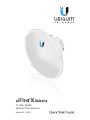
airFiber
®
Dish Antenna
Model: AF‑11G35

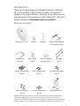
Introduction
Thank you for purchasing the Ubiquiti Networks® airFiberX
AF‑11G35 Antenna. This Quick Start Guide is designed to
guide you through installation. Warranty terms, safety notices,
and compliance information are in the airFiberAF-11G35 User
Guide, available at: downloads.ubnt.com/airfiber
Package Contents
airFiber AF‑11G35 Shroud I‑Bracket Upper Mount Bracket
with Elevation Rod
Lower Mount
Bracket
Pole Clamps
(Qty. 2)
Azimuth Support
Brackets (Qty. 2)
RF Cables
(Qty. 2)
Large Carriage Bolts
(Qty. 4)
Small Carriage Bolts
(Qty. 2)
Serrated Flange Bolts
(Qty. 4)
11 GHz airFiber
Dish Antenna
Model: AF-11G35
Bolts with Washers
(Qty. 4)
Serrated Flange Nuts
(Qty. 6)
Quick Start Guide
TERMS OF USE: Ubiquiti radio devices must be professionally installed. Shielded Ethernet
cable and earth grounding must be used as conditions of product warranty. It is the
customer’s responsibility to follow local country regulations, including operation within legal
frequency channels, output power, and Dynamic Frequency Selection (DFS) requirements.

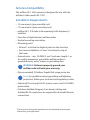
Antenna Compatibility
The airFiber AF‑11G35 antenna is designed for use with the
airFiberX radio model AF-11FX
*
.
Installation Requirements
• 13 mm wrench (pre‑assembly tool)
• 17 mm wrench (pole‑mounting tool)
• airFiber AF-11FX radio (sold separately) with duplexer(s)
installed
• Clear line of sight between airFiber radios
• Vertical mounting orientation
• Mounting point:
• At least 1 m below the highest point on the structure
• For tower installations, at least 3 m below the top of
thetower
• Ground wires – min. 10 AWG (5 mm
2
) and max. length:1m.
Asa safety precaution, ground the airFiber radios to
grounded masts, poles, towers, or grounding bars.
WARNING: Failure to properly ground your
airFiber radio will void your warranty.
• (Recommended) 2 Outdoor Gigabit PoE surge protectors
Note: For guidelines about grounding and lightning
protection, follow your local electrical regulatory codes.
• (Optional) If not using PoE: DC power source and 12/30 AWG
power cable.
• Outdoor, shielded Category 6 (or above) cabling and
shielded RJ‑45 connectors are required for all wired Ethernet
connections.
* Check your local/regional regulations for the allowable antenna gain
allowed for your application.

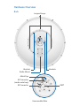
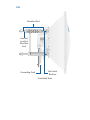
Hardware Overview
Back
Lanyard Loops
Brackets
Radio Mount
Brackets
RF Connector
OMT
RF Connector
(under metal cap)
Metal Cap
Unassembled View

Side
Elevation Rod
Hex Nut
to adjust
Elevation
Rod
Bolts with
Washers
Grounding Point
Assembled View

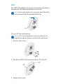
OMT
The OMT (OrthoMode Transducer) is located on the back of
the antenna. The default polarization is H and V.
Note: If you only need to use one port, keep the other
one covered with the included Metal Cap.
H
V
To use ±45° slant polarization:
Note: ±45° slant polarization is not permitted in all
regulatory regions. Please consult local regulations.
1. Remove the screws.
2. Rotate the OMT so the arrows point to ‑45° and +45°.
-45°
+45°
3. Replace the screws.

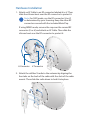
Hardware Installation
1. Attach an RF Cable to an RF connector labeled H or V. Then
slide the silicone boot over the RF connector to protect it.
Note: For SISO mode, use the RF connector (H or V)
as determined by your licensing. Keep the other RF
connector covered with the included Metal Cap.
If using MIMO mode, remove the cap over the second RF
connector (V or H) and attach an RF Cable. Then slide the
silicone boot over the RF connector to protect it.
H Connector
V Connector
2. Attach the airFiber X radio to the antenna by aligning the
four tabs on the back of the radio with the slots of the radio
mount. Then slide the radio down to lock it into place.

3. Connect the RF Cable(s) (one in SISO mode, two in MIMO
mode) to the radio as follows:
• Attach the RF Cable from the H Connector to the radio’s
Chain0 connector.
• Attach the RF Cable from the V Connector to the radio’s
Chain1 connector.
Chain 1
Chain 0
V Connector
H Connector

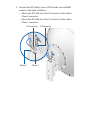
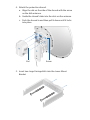
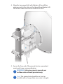
4. Attach the protective shroud.
a. Align the dot on the side of the shroud with the arrow
on the dish antenna.
b. Guide the shroud’s tabs into the slots on the antenna.
c. Push the shroud in and then pull it down until it locks
into place.
Dot Arrow
5. Insert two Large Carriage Bolts into the Lower Mount
Bracket.

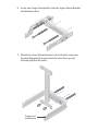
6. Insert two Large Carriage Bolts into the Upper Mount Bracket
with Elevation Rod.
7. Attach the Lower Mount Bracket to the I-Bracket using two
Serrated Flange Bolts. Ensure that the slots face up and
securely tighten the bolts.
Proper slot
orientation

8. Attach the Upper Mount Bracket with Elevation Rod to the
I-Bracket using two Serrated Flange Bolts.
Note: Ensure that the orientation of the Upper Mount
Bracket matches the illustration below, with the
Elevation Rod on the correct side.

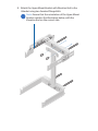
9. Attach the Pole Clamps to the Mount Brackets.
a. Slide the slotted hole of each Pole Clamp over one
upper and one lower Large CarriageBolt.
b. Place one Serrated Flange Nut on each Large
CarriageBolt.

10. Prepare the Azimuth Support Brackets for mounting.
a. Insert the two Small Carriage Bolts into the Azimuth
Support Bracket that has two slotted holes.
b. Slide the slotted hole of the other Azimuth Support
Bracket over one SmallCarriage Bolt.
c. Place one Serrated Flange Nut on each Small
CarriageBolt.
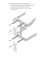
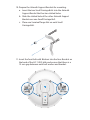
11. Insert the four Bolts with Washers into the four Brackets on
the back of the AF‑11G35 dish and ensure that there is a
13mm gap between each bolt washer and bracket.
13 mm
13 mm

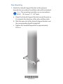
Pole‑Mounting
1. Attach the Azimuth Support Brackets to the pole just
beneath the area where the airFiber radio will be attached.
Note: The mounting assembly can accommodate a
Ø 38.1 ‑ 101.6 mm (1.5" ‑ 4.0") pole.
a. Orient the Azimuth Support Brackets around the pole so
it is aimed in the direction of the other airFiber radio.
b. Slide the open slot of the Azimuth Support Bracket over
the corresponding SmallCarriage Bolt.
c. Tighten the Serrated Flange Nuts to approximately
50N · m.
*640-00259-02*
640-00259-02

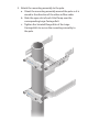
2. Attach the mounting assembly to the pole.
a. Orient the mounting assembly around the pole so it is
aimed in the direction of the other airFiber radio.
b. Slide the open slot of each Pole Clamp over the
corresponding Large CarriageBolt.
c. Tighten the Serrated Flange Nuts of the Large
CarriageBolts to secure the mounting assembly to
thepole.

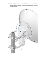
3. Lift the airFiber antenna and align the two lower Bolts with
Washers with the slots on the Lower Mount Bracket. Seat the
bolts in the slots.

4. Align the two upper Bolts with Washers of the airFiber
antenna next to the slots on the Upper Mount Bracket. Lift
the airFiber radio and seat the bolts in theslots.
5. Secure the free end of the ground wire to a grounded
mast, pole, tower, or grounding bar.
WARNING: Failure to properly ground your
airFiber radio will void your warranty.
Note: The ground wire should be as short as
possible and no longer than one meter in length.

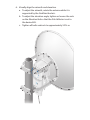
6. Visually align the azimuth and elevation.
a. To adjust the azimuth, rotate the antenna while it is
supported by the Stabilizer Brackets.
b. To adjust the elevation angle, tighten or loosen the nuts
on the Elevation Rod so that the Dish Reflector is set to
the desired tilt.
c. Tighten all bolts and nuts to approximately 50N ∙ m.

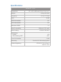
Specifications
airFiber AF‑11G35
Dimensions 811 x 811 x 460 mm (31.9 x 31.9 x 18.1")
Weight 16.5 kg (36.38 lb)
Frequency 10.3 to 11.7 GHz
Gain 35 dBi
HPOL Beamwidth 2.5°
VPOL Beamwidth 2.5°
Maximum VSWR 2:1
Wind Survivability 200 km/h (125 mph)
Wind Loading 1538 N @ 200 km/h
Polarization
Default
After Rotating OMT
H/V
±45°
Cross‑Pol Isolation 35 dB
Mounting Uses the AF‑5 Mounting System
Pattern Regulatory ETSI 302 217‑4‑2, Class 3
and FCC Cat B

Safety Notices
1. Read, follow, and keep these instructions.
2. Heed all warnings.
3. Only use attachments/accessories specified by the manufacturer.
WARNING: Do not use this product in location that can
be submerged by water.
WARNING: Avoid using this product during an electrical
storm. There may be a remote risk of electric shock from
lightning.
Electrical Safety Information
1. Compliance is required with respect to voltage, frequency, and current
requirements indicated on the manufacturer’s label. Connection to a
different power source than those specified may result in improper
operation, damage to the equipment or pose a fire hazard if the
limitations are not followed.
2. There are no operator serviceable parts inside this equipment. Service
should be provided only by a qualified service technician.
Pagina se încarcă ...
Pagina se încarcă ...
Pagina se încarcă ...
Pagina se încarcă ...
Pagina se încarcă ...
Pagina se încarcă ...
Pagina se încarcă ...
Pagina se încarcă ...
-
 1
1
-
 2
2
-
 3
3
-
 4
4
-
 5
5
-
 6
6
-
 7
7
-
 8
8
-
 9
9
-
 10
10
-
 11
11
-
 12
12
-
 13
13
-
 14
14
-
 15
15
-
 16
16
-
 17
17
-
 18
18
-
 19
19
-
 20
20
-
 21
21
-
 22
22
-
 23
23
-
 24
24
-
 25
25
-
 26
26
-
 27
27
-
 28
28


Ubiquiti AF-11G35 Ghid de inițiere rapidă
- Categorie
- Antene de rețea
- Tip
- Ghid de inițiere rapidă
în alte limbi
- English: Ubiquiti AF-11G35 Quick start guide
- italiano: Ubiquiti AF-11G35 Guida Rapida
Lucrări conexe
-
Ubiquiti AF-5G23-S45 Ghid de inițiere rapidă
-
Ubiquiti Networks AF-24 Manualul utilizatorului
-
Ubiquiti airMAX AM-2G15-120 Ghid de inițiere rapidă
-
-
-
-
-
-
Ubiquiti Networks RD-5G30 Manualul utilizatorului
-