
DOC023.98.80047
sc200 Conductivity Module
03/2020, Edition 4
User Manual
Benutzerhandbuch
Manuale utente
Manuel d'utilisation
Manual del usuario
Manual do utilizador
Návod k použití
Brugervejledning
Gebruikershandleiding
Instrukcja obsługi
Bruksanvisning
Käyttöopas
Ръководство за потребителя
Felhasználói kézikönyv
Manual de utilizare
Naudotojo vadovas
Руководство пользователя
Kullanıcı Kılavuzu
Návod na použitie
Navodila za uporabo
Korisnički priručnik
Εγχειρίδιο χρήστη
Kasutusjuhend

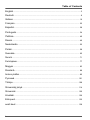
Table of Contents
English..............................................................................................................................3
Deutsch............................................................................................................................ 9
Italiano............................................................................................................................ 16
Français......................................................................................................................... 22
Español.......................................................................................................................... 28
Português...................................................................................................................... 34
Čeština........................................................................................................................... 40
Dansk..............................................................................................................................46
Nederlands....................................................................................................................52
Polski.............................................................................................................................. 58
Svenska......................................................................................................................... 65
Suomi..............................................................................................................................71
български..................................................................................................................... 77
Magyar........................................................................................................................... 83
Română......................................................................................................................... 89
lietuvių kalba.................................................................................................................95
Русский........................................................................................................................101
Türkçe...........................................................................................................................108
Slovenský jazyk......................................................................................................... 114
Slovenski..................................................................................................................... 120
Hrvatski........................................................................................................................ 126
Ελληνικά...................................................................................................................... 132
eesti keel..................................................................................................................... 139
2

Table of Contents
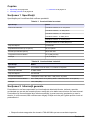
1 Specifications on page 3
2 General information on page 3
3 Installation on page 5
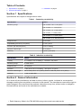
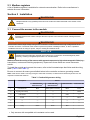
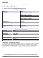
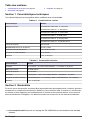
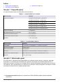
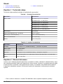
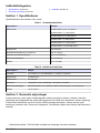
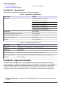
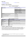
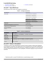
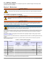
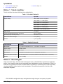
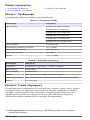
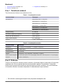
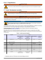
Section 1 Specifications
Specifications are subject to change without notice.
Table 1 Contacting conductivity
Specification Details
Measuring range Cell constant 0.05: 0–100 µS/cm
Cell constant 0.1: 0–200 µS/cm
Cell constant 0.5: 0–1000 µS/cm
Cell constant 1: 0–2000 µS/cm
Cell constant 5: 0–10,000 µS/cm
Cell constant 10: 0–200,000 µS/cm
Response time 0.5 seconds
Repeatability/precision (0–20 µS/cm) ±0.1/0.1 µS/cm
Precision (20–200,000 µS/cm) ±0.5% of reading
Maximum cable length 91 m (300 ft)
Warranty 1 year; 2 years (EU)
Table 2 Inductive conductivity
Specification Details
Linearity ≥ 1.5 mS/cm: ±1% of reading; < 1.5 mS/cm: ±15 µS/cm
Measuring range 0–2000 mS/cm
Response time 0.5 seconds
Precision
1
> 500 µS/cm: ±0.5% of reading; < 500 µS/cm: ±5 µS/cm
Maximum cable length 200 to 2000 µS/cm: 61 m (200 ft); 2000 to 2,000,000 µS/cm: 91 m (300 ft)
Warranty 1 year; 2 years (EU)
Section 2 General information
In no event will the manufacturer be liable for direct, indirect, special, incidental or consequential
damages resulting from any defect or omission in this manual. The manufacturer reserves the right to
make changes in this manual and the products it describes at any time, without notice or obligation.
Revised editions are found on the manufacturer’s website.
1
Radio frequency fields in the 700–800 MHz range can cause inaccurate results.
English 3

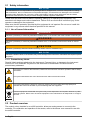
2.1 Safety information
N O T I C E
The manufacturer is not responsible for any damages due to misapplication or misuse of this product including,
without limitation, direct, incidental and consequential damages, and disclaims such damages to the full extent
permitted under applicable law. The user is solely responsible to identify critical application risks and install
appropriate mechanisms to protect processes during a possible equipment malfunction.
Please read this entire manual before unpacking, setting up or operating this equipment. Pay
attention to all danger and caution statements. Failure to do so could result in serious injury to the
operator or damage to the equipment.
Make sure that the protection provided by this equipment is not impaired. Do not use or install this
equipment in any manner other than that specified in this manual.
2.1.1 Use of hazard information
D A N G E R
Indicates a potentially or imminently hazardous situation which, if not avoided, will result in death or serious injury.
W A R N I N G
Indicates a potentially or imminently hazardous situation which, if not avoided, could result in death or serious
injury.
C A U T I O N
Indicates a potentially hazardous situation that may result in minor or moderate injury.
N O T I C E
Indicates a situation which, if not avoided, may cause damage to the instrument. Information that requires special
emphasis.
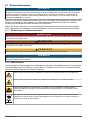
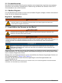
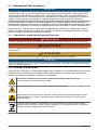
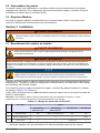
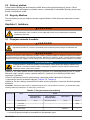
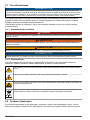
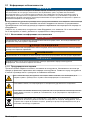
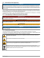
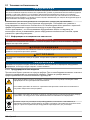
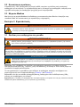
2.1.2 Precautionary labels
Read all labels and tags attached to the instrument. Personal injury or damage to the instrument
could occur if not observed. A symbol on the instrument is referenced in the manual with a
precautionary statement.
This symbol, if noted on the instrument, references the instruction manual for operation and/or safety
information.
This symbol indicates that a risk of electrical shock and/or electrocution exists.
This symbol indicates the presence of devices sensitive to Electro-static Discharge (ESD) and
indicates that care must be taken to prevent damage with the equipment.
Electrical equipment marked with this symbol may not be disposed of in European domestic or public
disposal systems. Return old or end-of-life equipment to the manufacturer for disposal at no charge to
the user.
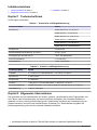
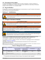
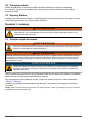
2.2 Product overview
The module, when installed in an sc200 controller, allows an analog sensor to connect to the
controller. For calibration and operation of the sensor, refer to the sensor user manual for use with
the sc200 controller.
4
English

2.3 Modbus registers
A list of Modbus registers is available for network communication. Refer to the manufacturer's
website for more information.
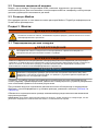
Section 3 Installation
W A R N I N G
Multiple hazards. Only qualified personnel must conduct the tasks described in this section of the
document.
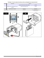
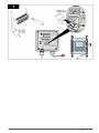
3.1 Connect the sensor to the module
W A R N I N G
Potential Electrocution Hazard. Always disconnect power to the instrument when making electrical
connections.
W A R N I N G
Electrocution Hazard. High voltage wiring for the controller is conducted behind the high voltage barrier in the
controller enclosure. The barrier must remain in place except when installing modules, or when a qualified
installation technician is wiring for power, relays or analog and network cards.
N O T I C E
Potential Instrument Damage. Delicate internal electronic components can be damaged by static
electricity, resulting in degraded performance or eventual failure.
Make sure that the routing of the sensor cable prevents exposure to high electromagnetic fields (e.g.,
transmitters, motors and switching equipment). Exposure to these fields can cause inaccurate
results.
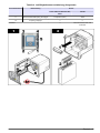
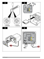
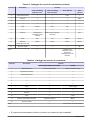
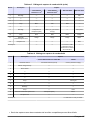
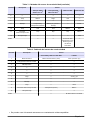
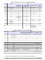
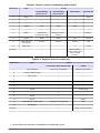
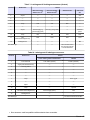
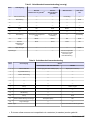
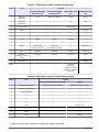
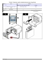
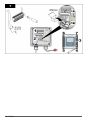
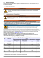
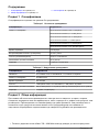
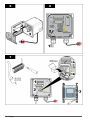
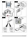
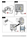
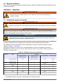
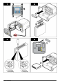
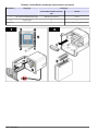
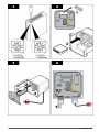
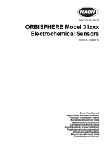
To install the module and connect the sensor, refer to the illustrated steps that follow and the wiring
table (Table 3 and Table 4).
Be sure to connect all sensor ground/shield wires to the controller enclosure grounding screws.
Note: If the sensor cable is not long enough to reach the controller, an interconnect cable and junction box are
required to extend the distance.
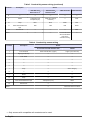
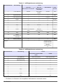
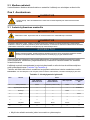
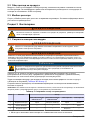
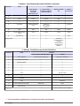
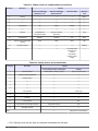
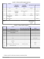
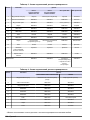
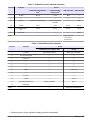
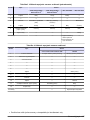
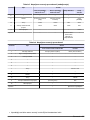
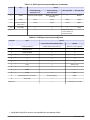
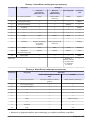
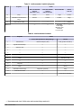
Table 3 Conductivity sensor wiring
Terminal Description Sensor
83xx that uses
Z08319=A=1115
2
83xx that uses
Z08319=A=00xx
2
3400 series GLI 3700 series GLI
1 Inner electrode Black White (yellow connector) Black Green
2 Signal ground/Temp — — — Yellow
3 Inner shield — — Clear —
4 Shield — — — Black
5 — — — — —
6 — — — — —
7 Temp White Black Blue —
2
Only sensors with compatible cell constants can be used.
English 5

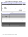
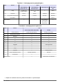
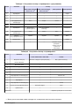
Table 3 Conductivity sensor wiring (continued)
Terminal Description Sensor
83xx that uses
Z08319=A=1115
2
83xx that uses
Z08319=A=00xx
2
3400 series GLI 3700 series GLI
8 — — — — —
9 Shield Transparent and
transparent (foil)
White (2x) (orange
connector)
— Clear
10 Temp Blue Blue White Red
11 Outer electrode/Receive
high
Red Red Red White
12 Receive low — — — Blue
Notes: — — Connect the clear
wire with the black
band to the
controller housing.
—
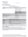
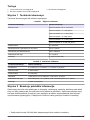
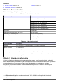
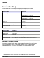
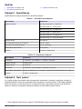
Table 4 Conductivity sensor wiring
Terminal Description Sensor
Crison 5395 and 5396 with AS9 cable LZY082
1 Inner electrode Outer stranded wire (copper) Copper (red connector)
2 Signal ground/Temp — —
3 Inner shield — —
4 — — —
5 — — —
6 — — —
7 Temp — Green and gray
8 — — —
9 Shield — —
10 Temp — Pink
11 Outer electrode/Receive high Transparent (core) White
12 Receive low — —
Notes: — The brown wire is not used.
2
Only sensors with compatible cell constants can be used.
6 English

English 7

8 English

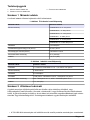
Inhaltsverzeichnis
1 Technische Daten auf Seite 9
2 Allgemeine Informationen auf Seite 9
3 Installation auf Seite 11
Kapitel 1 Technische Daten
Änderungen vorbehalten.
Tabelle 1 Konduktive Leitfähigkeitsmessung
Technische Daten Details
Messbereich Zellkonstante 0,05: 0–100 µS/cm
Zellkonstante 0,1: 0–200 µS/cm
Zellkonstante 0,5: 0–1000 µS/cm
Zellkonstante 1: 0–2000 µS/cm
Zellkonstante 5: 0–10,000 µS/cm
Zellkonstante 10: 0–200,000 µS/cm
Ansprechzeit 0,5 Sekunden
Wiederholbarkeit//Genauigkeit (0–20 µS/cm) ±0,1/0,1 µS/cm
Genauigkeit (20–200,000 µS/cm) ± 0,5% des Messwertes
Maximale Kabellänge 91 m (300 Fuß)
Gewährleistung 1 Jahr; 2 Jahre (EU)
Tabelle 2 Induktive Leitfähigkeitsmessung
Technische Daten Details
Linearität ≥ 1,5 mS/cm: ±1% des Messwerts; < 1,5 mS/cm: ±15 µS/cm
Messbereich 0–2000 mS/cm
Ansprechzeit 0,5 Sekunden
Präzision
1
> 500 µS/cm: ±0,5% des Messwerts; < 500 µS/cm: ±5 µS/cm
Maximale Kabellänge 200 bis 2000 µS/cm: 61 m (200 ft); 2000 bis 2.000.000 µS/cm: 91 m (300 ft)
Gewährleistung 1 Jahr; 2 Jahre (EU)
Kapitel 2 Allgemeine Informationen
Der Hersteller ist nicht verantwortlich für direkte, indirekte, versehentliche oder Folgeschäden, die
aus Fehlern oder Unterlassungen in diesem Handbuch entstanden. Der Hersteller behält sich
jederzeit und ohne vorherige Ankündigung oder Verpflichtung das Recht auf Verbesserungen an
diesem Handbuch und den hierin beschriebenen Produkten vor. Überarbeitete Ausgaben der
Bedienungsanleitung sind auf der Hersteller-Webseite erhältlich.
1
Hochfrequenzfelder im Bereich 700–800 MHz können zu falschen Ergebnissen führen.
Deutsch 9

2.1 Sicherheitshinweise
H I N W E I S
Der Hersteller ist nicht für Schäden verantwortlich, die durch Fehlanwendung oder Missbrauch dieses Produkts
entstehen, einschließlich, aber ohne Beschränkung auf direkte, zufällige oder Folgeschäden, und lehnt jegliche
Haftung im gesetzlich zulässigen Umfang ab. Der Benutzer ist selbst dafür verantwortlich, schwerwiegende
Anwendungsrisiken zu erkennen und erforderliche Maßnahmen durchzuführen, um die Prozesse im Fall von
möglichen Gerätefehlern zu schützen.
Bitte lesen Sie dieses Handbuch komplett durch, bevor Sie dieses Gerät auspacken, aufstellen oder
bedienen. Beachten Sie alle Gefahren- und Warnhinweise. Nichtbeachtung kann zu schweren
Verletzungen des Bedieners oder Schäden am Gerät führen.
Stellen Sie sicher, dass die durch dieses Messgerät bereitgestellte Sicherheit nicht beeinträchtigt
wird. Verwenden bzw. installieren Sie das Messsystem nur wie in diesem Handbuch beschrieben.
2.1.1 Bedeutung von Gefahrenhinweisen
G E F A H R
Kennzeichnet eine mögliche oder drohende Gefahrensituation, die, wenn sie nicht vermieden wird, zum Tod oder
zu schweren Verletzungen führt.
W A R N U N G
Kennzeichnet eine mögliche oder drohende Gefahrensituation, die, wenn sie nicht vermieden wird, zum Tod oder
zu schweren Verletzungen führen kann.
V O R S I C H T
Kennzeichnet eine mögliche Gefahrensituation, die zu leichteren Verletzungen führen kann.
H I N W E I S
Kennzeichnet eine Situation, die, wenn sie nicht vermieden wird, das Gerät beschädigen kann. Informationen, die
besonders beachtet werden müssen.
2.1.2 Warnhinweise
Lesen Sie alle am Gerät angebrachten Aufkleber und Hinweise. Nichtbeachtung kann Verletzungen
oder Beschädigungen des Geräts zur Folge haben. Im Handbuch wird in Form von Warnhinweisen
auf die am Gerät angebrachten Symbole verwiesen.
Dieses Symbol am Gerät weist auf Betriebs- und/oder Sicherheitsinformationen im Handbuch hin.
Dieses Symbol weist auf die Gefahr eines elektrischen Schlages hin, der tödlich sein kann.
Dieses Symbol zeigt das Vorhandensein von Geräten an, die empfindlich auf elektrostatische
Entladung reagieren. Es müssen Vorsichtsmaßnahmen getroffen werden, um die Geräte nicht zu
beschädigen.
Elektrogeräte, die mit diesem Symbol gekennzeichnet sind, dürfen nicht im normalen öffentlichen
Abfallsystem entsorgt werden. Senden Sie Altgeräte an den Hersteller zurück. Dieser entsorgt die
Geräte ohne Kosten für den Benutzer.
10 Deutsch

2.2 Produktübersicht
Das Modul wird in einem sc200-Controller installiert und ermöglicht den Anschluss eines analogen
Sensors an den Controller. Informationen zu Kalibrierung und Betrieb des Sensors finden Sie im
Sensorhandbuch zum sc200-Controller.
2.3 Modbus-Register
Für die Netzwerkkommunikation ist eine Liste der Modbus-Register verfügbar. Weitere Informationen
finden Sie auf der Website des Herstellers.
Kapitel 3 Installation
W A R N U N G
Mehrere Gefahren. Nur qualifiziertes Personal sollte die in diesem Kapitel des Dokuments
beschriebenen Aufgaben durchführen.
3.1 Anschließen des Sensors an das Modul
W A R N U N G
Potenzielle Stromschlaggefahr. Stellen Sie stets die Spannungsversorgung am Gerät ab, wenn
elektrische Anschlüsse durchgeführt werden.
W A R N U N G
Gefahr durch elektrischen Schlag. Die Hochspannungsleitungen für die Steuerung verlaufen hinter der
Hochspannungssperre im Steuerungsgehäuse. Die Sperre muss eingebaut bleiben, außer bei der Installation von
Modulen oder wenn ein qualifizierter Installationstechniker die Stromversorgung, Relais oder Netzkarten
anschließt.
H I N W E I S
Möglicher Geräteschaden Empfindliche interne elektronische Bauteile können durch statische
Elektrizität beschädigt werden, wobei dann das Gerät mit verminderter Leistung funktioniert oder
schließlich ganz ausfällt.
Stellen Sie sicher, dass die Führung des Sensorkabels eine Gefährdung durch elektromagnetische
Felder verhindert (z. B. Transmitter, Motoren und Schalteinrichtungen). Die Einwirkung dieser Felder
kann zu falschen Ergebnissen führen.
Befolgen Sie zum Einbau des Moduls und zum Anschließen des Sensors die gezeigten Schritte und
die Verdrahtungstabelle (Tabelle 3 und Tabelle 4).
Schließen Sie alle Sensormasse-/Abschirmungsleitungen an die Erdungsschrauben des
Controllergehäuses an.
Hinweis: Wenn das Sensorkabel nicht bis zum Controller reicht, ist ein Verbindungskabel mit Anschlusskasten
erforderlich, um die Entfernung zu überbrücken.
Deutsch
11

Tabelle 3 Leitfähigkeitssenorverkabelung
Anschlussklemme Beschreibung Sensor
83xx, das
Z08319=A=1115 verwendet
2
83xx, das
Z08319=A=00xx
verwendet
2
Serie 3400 GLI Serie
3700 GLI
1 Innere Elektrode Schwarz Weiß (gelber
Stecker)
Schwarz Grün
2 Signalmasse/Temp — — — Gelb
3 Innere Abschirmung — — Löschen —
4 Schirm — — — Schwarz
5 — — — — —
6 — — — — —
7 Temp. Weiß Schwarz Blau —
8 — — — — —
9 Schirm Transparent und transparent
(Folie)
Weiß (2x)
(oranger Stecker)
— Löschen
10 Temp. Blau Blau Weiß Rot
11 Äußere
Elektrode/Empfang
Hochpegel
Rot Rot Rot Weiß
12 Empfang Tiefpegel — — — Blau
Hinweise: — — Schließen Sie den
transparenten Draht
mit dem schwarzen
Band am
Controllergehäuse
an.
—
Tabelle 4 Leitfähigkeitssenorverkabelung
Anschlussklemme Beschreibung Sensor
Crison 5395 und 5396 mit AS9-
Kabel
LZY082
1 Innere Elektrode Äußere Litze (Kupfer) Kupfer (roter Stecker)
2 Signalmasse/Temp — —
3 Innere Abschirmung — —
4 — — —
5 — — —
6 — — —
7 Temp. — Grün und grau
8 — — —
9 Schirm — —
10 Temp. — Pink
2
Es können nur Sensoren mit kompatiblen Zellkonstanten verwendet werden.
12 Deutsch

Tabelle 4 Leitfähigkeitssenorverkabelung (fortgesetzt)
Anschlussklemme Beschreibung Sensor
Crison 5395 und 5396 mit AS9-
Kabel
LZY082
11 Äußere Elektrode/Empfang Hochpegel Transparent (Ader) Weiß
12 Empfang Tiefpegel — —
Hinweise: — Der braune Draht wird nicht
verwendet.
Deutsch 13

14 Deutsch

Deutsch 15

Sommario
1 Specifiche tecniche a pagina 16
2 Informazioni generali a pagina 16
3 Installazione a pagina 18
Sezione 1 Specifiche tecniche
Le specifiche tecniche sono soggette a modifica senza preavviso.
Tabella 1 conducibilità a contatto
Dato tecnico Dettagli
Range di misura Costante di cella 0.05: 0-100 µS/cm
Costante di cella 0.1: 0-200 µS/cm
Costante di cella 0.5: 0-1000 µS/cm
Costante di cella 1: 0-2000 µS/cm
Costante di cella 5: 0-10,000 µS/cm
Costante di cella 10: 0-200,000 µS/cm
Tempo di risposta 0,5 secondi
Ripetibilità/precisione (0–20 µS/cm) ±0,1/0,1 µS/cm
Precisione (20–200.000 µS/cm) ± 0,5% di lettura
Lunghezza massima del cavo 91 m (300 pd)
Garanzia 1 anno; 2 anni (EU)
Tabella 2 .Conducibilità induttiva
Dato tecnico Dettagli
Linearità ≥ 1,5 mS/cm: ±1% di lettura; < 1,5 mS/cm: ±15 µS/cm
Range di misura 0–2000 mS/cm
Tempo di risposta 0,5 secondi
Precisione
1
> 500 µS/cm: ±0,5% di lettura; < 500 µS/cm: ±5 µS/cm
Lunghezza massima del cavo Da 200 a 2000 µS/cm: 61 m (200 piedi); da 2000 a 2.000.000 µS/cm: 91 m
(300 piedi)
Garanzia 1 anno; 2 anni (EU)
Sezione 2 Informazioni generali
In nessun caso, il produttore potrà essere ritenuto responsabile per danni diretti, indiretti o accidentali
per qualsiasi difetto o omissione relativa al presente manuale. Il produttore si riserva il diritto di
apportare eventuali modifiche al presente manuale e ai prodotti ivi descritti in qualsiasi momento
senza alcuna notifica o obbligo preventivi. Le edizioni riviste sono presenti nel sito Web del
produttore.
1
I campi a radiofrequenza nell'intervallo 700–800 MHz possono determinare risultati imprecisi.
16 Italiano

2.1 Informazioni sulla sicurezza
A V V I S O
Il produttore non sarà da ritenersi responsabile in caso di danni causati dall'applicazione errata o dall'uso errato di
questo prodotto inclusi, a puro titolo esemplificativo e non limitativo, i danni incidentali e consequenziali; inoltre
declina qualsiasi responsabilità per tali danni entro i limiti previsti dalle leggi vigenti. La responsabilità relativa
all'identificazione dei rischi critici dell'applicazione e all'installazione di meccanismi appropriati per proteggere le
attività in caso di eventuale malfunzionamento dell'apparecchiatura compete unicamente all'utilizzatore.
Prima di disimballare, installare o utilizzare l’apparecchio, si prega di leggere l’intero manuale. Si
raccomanda di leggere con attenzione e rispettare le istruzioni riguardanti note di pericolosità. La non
osservanza di tali indicazioni potrebbe comportare lesioni gravi all'operatore o danni all'apparecchio.
Assicurarsi che i dispositivi di sicurezza insiti nell'apparecchio siano efficaci all'atto della messa in
servizio e durante l'utilizzo dello stesso. Non utilizzare o installare questa apparecchiatura in modo
diverso da quanto specificato nel presente manuale.
2.1.1 Indicazioni e significato dei segnali di pericolo
P E R I C O L O
Indica una situazione di pericolo potenziale o imminente che, se non evitata, causa lesioni gravi anche mortali.
A V V E R T E N Z A
Indica una situazione di pericolo potenziale o imminente che, se non evitata, potrebbe comportare lesioni gravi,
anche mortali.
A T T E N Z I O N E
Indica una situazione di pericolo potenziale che potrebbe comportare lesioni lievi o moderate.
A V V I S O
Indica una situazione che, se non evitata, può danneggiare lo strumento. Informazioni che richiedono particolare
attenzione da parte dell'utente.
2.1.2 Etichette di avvertimento
Leggere tutte le etichette e i contrassegni presenti sullo strumento. La mancata osservanza di questi
avvertimenti può causare lesioni personali o danni allo strumento. Un simbolo sullo strumento è
indicato nel manuale unitamente a una frase di avvertenza.
Tale simbolo, se apposto sullo strumento, fa riferimento al manuale delle istruzioni per il
funzionamento e/o informazioni sulla sicurezza.
Questo simbolo indica un rischio di scosse elettriche e/o elettrocuzione.
Questo simbolo indica la presenza di dispositivi sensibili alle scariche elettrostatiche (ESD, Electro-
static Discharge) ed è pertanto necessario prestare la massima attenzione per non danneggiare
l'apparecchiatura.
Le apparecchiature elettriche contrassegnate con questo simbolo non possono essere smaltite
attraverso sistemi domestici o pubblici europei. Restituire le vecchie apparecchiature al produttore il
quale si occuperà gratuitamente del loro smaltimento.
Italiano 17

2.2 Panoramica del prodotto
Il modulo, se installato in un controller sc200, consente di collegare un sensore analogico al
controller. Per la calibrazione e l'utilizzo del sensore, fare riferimento al manuale per l'utente del
sensore relativo all'utilizzo con il controller sc200.
2.3 Registri Modbus
È disponibile un elenco dei registri Modbus per la comunicazione in rete. Per ulteriori informazioni,
fare riferimento al sito Web del produttore.
Sezione 3 Installazione
A V V E R T E N Z A
Pericoli multipli. Gli interventi descritti in questa sezione del documento devono essere eseguiti solo
da personale qualificato.
3.1 Collegare il sensore al modulo
A V V E R T E N Z A
Rischio potenziale di scossa elettrica. Quando si eseguono collegamenti elettrici, scollegare sempre
l'alimentazione allo strumento.
A V V E R T E N Z A
Rischio di scossa elettrica. Il cablaggio ad alta tensione per il controller viene trasmesso attraverso la protezione
per l'alta tensione nell'alloggiamento del controller. La barriera deve rimanere in posizione tranne quando si
installano i moduli oppure quando un addetto all'installazione qualificato esegue i cablaggi per l'alimentazione, i
relè o le schede di rete e analogiche.
A V V I S O
Danno potenziale allo strumento. Componenti elettronici interni delicati possono essere danneggiati
dall'elettricità statica, compromettendo le prestazioni o provocando guasti.
Verificare che l'instradamento del cavo del sensore sia tale da impedire l'esposizione a campi
elettromagnetici di elevata intensità (ad esempio, trasmettitori, motori e attrezzature di
commutazione). L'esposizione a tali campi può causare risultati non precisi.
Per installare il modulo e collegare il sensore, fare riferimento ai passaggi illustrati e alla tabella di
cablaggio (Tabella 3 e Tabella 4).
Assicurarsi di collegare tutti i fili di terra/schermatura del sensore alle viti di messa a terra
dell'armadietto del controller.
Nota: Se il cavo del sensore non è sufficientemente lungo da raggiungere il controller, sono necessari un cavo di
interconnessione e una scatola di connessione per coprire la distanza.
Tabella 3 Cablaggio dei sensori di conduttività
Terminale Descrizione Sensore
83xx che utilizza
Z08319=A=1115
2
83xx che utilizza
Z08319=A=00xx
2
Serie 3400 GLI Serie
3700 GLI
1 Elettrodo interno Nero Bianco (connettore
giallo)
Nero Verde
2 Segnale di terra/Temp — — — Giallo
2
È consentito esclusivamente l'utilizzo di sensori con costanti di cella compatibili.
18 Italiano

Tabella 3 Cablaggio dei sensori di conduttività (continua)
Terminale Descrizione Sensore
83xx che utilizza
Z08319=A=1115
2
83xx che utilizza
Z08319=A=00xx
2
Serie 3400 GLI Serie
3700 GLI
3 Schermatura interna — — Canc. —
4 Schermo — — — Nero
5 — — — — —
6 — — — — —
7 Temp Bianco Nero Blu —
8 — — — — —
9 Schermo Trasparente e
trasparente (foglio
isolante)
Bianco (2x) (connettore
arancione)
— Canc.
10 Temp Blu Blu Bianco Rosso
11 Elettrodo
esterno/Ricezione alta
Rosso Rosso Rosso Bianco
12 Ricezione bassa — — — Blu
Note: — — Collegare il filo
trasparente con la
banda nera
all'alloggiamento del
controller.
—
Tabella 4 Cablaggio dei sensori di conduttività
Terminale Descrizione Sensore
Crison 5395 e 5396 con cavo AS9 LZY082
1 Elettrodo interno Treccia esterna (rame) Rame (connettore rosso)
2 Segnale di terra/Temp — —
3 Schermatura interna — —
4 — — —
5 — — —
6 — — —
7 Temp — Verde e grigio
8 — — —
9 Schermo — —
10 Temp — Rosa
11 Elettrodo esterno/Ricezione alta Trasparente (anima) Bianco
12 Ricezione bassa — —
Note: — Il filo marrone non viene utilizzato.
2
È consentito esclusivamente l'utilizzo di sensori con costanti di cella compatibili.
Italiano 19

20 Italiano
Pagina se încarcă...
Pagina se încarcă...
Pagina se încarcă...
Pagina se încarcă...
Pagina se încarcă...
Pagina se încarcă...
Pagina se încarcă...
Pagina se încarcă...
Pagina se încarcă...
Pagina se încarcă...
Pagina se încarcă...
Pagina se încarcă...
Pagina se încarcă...
Pagina se încarcă...
Pagina se încarcă...
Pagina se încarcă...
Pagina se încarcă...
Pagina se încarcă...
Pagina se încarcă...
Pagina se încarcă...
Pagina se încarcă...
Pagina se încarcă...
Pagina se încarcă...
Pagina se încarcă...
Pagina se încarcă...
Pagina se încarcă...
Pagina se încarcă...
Pagina se încarcă...
Pagina se încarcă...
Pagina se încarcă...
Pagina se încarcă...
Pagina se încarcă...
Pagina se încarcă...
Pagina se încarcă...
Pagina se încarcă...
Pagina se încarcă...
Pagina se încarcă...
Pagina se încarcă...
Pagina se încarcă...
Pagina se încarcă...
Pagina se încarcă...
Pagina se încarcă...
Pagina se încarcă...
Pagina se încarcă...
Pagina se încarcă...
Pagina se încarcă...
Pagina se încarcă...
Pagina se încarcă...
Pagina se încarcă...
Pagina se încarcă...
Pagina se încarcă...
Pagina se încarcă...
Pagina se încarcă...
Pagina se încarcă...
Pagina se încarcă...
Pagina se încarcă...
Pagina se încarcă...
Pagina se încarcă...
Pagina se încarcă...
Pagina se încarcă...
Pagina se încarcă...
Pagina se încarcă...
Pagina se încarcă...
Pagina se încarcă...
Pagina se încarcă...
Pagina se încarcă...
Pagina se încarcă...
Pagina se încarcă...
Pagina se încarcă...
Pagina se încarcă...
Pagina se încarcă...
Pagina se încarcă...
Pagina se încarcă...
Pagina se încarcă...
Pagina se încarcă...
Pagina se încarcă...
Pagina se încarcă...
Pagina se încarcă...
Pagina se încarcă...
Pagina se încarcă...
Pagina se încarcă...
Pagina se încarcă...
Pagina se încarcă...
Pagina se încarcă...
Pagina se încarcă...
Pagina se încarcă...
Pagina se încarcă...
Pagina se încarcă...
Pagina se încarcă...
Pagina se încarcă...
Pagina se încarcă...
Pagina se încarcă...
Pagina se încarcă...
Pagina se încarcă...
Pagina se încarcă...
Pagina se încarcă...
Pagina se încarcă...
Pagina se încarcă...
Pagina se încarcă...
Pagina se încarcă...
Pagina se încarcă...
Pagina se încarcă...
Pagina se încarcă...
Pagina se încarcă...
Pagina se încarcă...
Pagina se încarcă...
Pagina se încarcă...
Pagina se încarcă...
Pagina se încarcă...
Pagina se încarcă...
Pagina se încarcă...
Pagina se încarcă...
Pagina se încarcă...
Pagina se încarcă...
Pagina se încarcă...
Pagina se încarcă...
Pagina se încarcă...
Pagina se încarcă...
Pagina se încarcă...
Pagina se încarcă...
Pagina se încarcă...
Pagina se încarcă...
Pagina se încarcă...
Pagina se încarcă...
Pagina se încarcă...
Pagina se încarcă...
-
 1
1
-
 2
2
-
 3
3
-
 4
4
-
 5
5
-
 6
6
-
 7
7
-
 8
8
-
 9
9
-
 10
10
-
 11
11
-
 12
12
-
 13
13
-
 14
14
-
 15
15
-
 16
16
-
 17
17
-
 18
18
-
 19
19
-
 20
20
-
 21
21
-
 22
22
-
 23
23
-
 24
24
-
 25
25
-
 26
26
-
 27
27
-
 28
28
-
 29
29
-
 30
30
-
 31
31
-
 32
32
-
 33
33
-
 34
34
-
 35
35
-
 36
36
-
 37
37
-
 38
38
-
 39
39
-
 40
40
-
 41
41
-
 42
42
-
 43
43
-
 44
44
-
 45
45
-
 46
46
-
 47
47
-
 48
48
-
 49
49
-
 50
50
-
 51
51
-
 52
52
-
 53
53
-
 54
54
-
 55
55
-
 56
56
-
 57
57
-
 58
58
-
 59
59
-
 60
60
-
 61
61
-
 62
62
-
 63
63
-
 64
64
-
 65
65
-
 66
66
-
 67
67
-
 68
68
-
 69
69
-
 70
70
-
 71
71
-
 72
72
-
 73
73
-
 74
74
-
 75
75
-
 76
76
-
 77
77
-
 78
78
-
 79
79
-
 80
80
-
 81
81
-
 82
82
-
 83
83
-
 84
84
-
 85
85
-
 86
86
-
 87
87
-
 88
88
-
 89
89
-
 90
90
-
 91
91
-
 92
92
-
 93
93
-
 94
94
-
 95
95
-
 96
96
-
 97
97
-
 98
98
-
 99
99
-
 100
100
-
 101
101
-
 102
102
-
 103
103
-
 104
104
-
 105
105
-
 106
106
-
 107
107
-
 108
108
-
 109
109
-
 110
110
-
 111
111
-
 112
112
-
 113
113
-
 114
114
-
 115
115
-
 116
116
-
 117
117
-
 118
118
-
 119
119
-
 120
120
-
 121
121
-
 122
122
-
 123
123
-
 124
124
-
 125
125
-
 126
126
-
 127
127
-
 128
128
-
 129
129
-
 130
130
-
 131
131
-
 132
132
-
 133
133
-
 134
134
-
 135
135
-
 136
136
-
 137
137
-
 138
138
-
 139
139
-
 140
140
-
 141
141
-
 142
142
-
 143
143
-
 144
144
-
 145
145
-
 146
146


în alte limbi
- slovenčina: Hach SC200 Používateľská príručka
- eesti: Hach SC200 Kasutusjuhend
Lucrări înrudite
-
Hach TU5300sc Quick Manual
-
Hach POLYMETRON 8312 Manual de utilizare
-
 Hach 9586sc Basic User Manual
-
 Hach pHD Sensor Manual de utilizare
-
Hach SC200 Basic User Manual
-
 Hach Chlorine Sensor Manual de utilizare
-
 Hach CLT10sc Manual de utilizare
-
 Hach ORBISPHERE 31285TC Basic User Manual
-
 Hach ORBISPHERE 31 series Basic User Manual
-
 Hach POLYMETRON 8810 ISE Basic User Manual


