Trumpf TruTool N 160 E Manual de utilizare
- Categorie
- Unelte electrice
- Tip
- Manual de utilizare

de Originalbetriebsanleitung
en Original instructions
fr Notice originale
es Manual original
pt Manual original
it Istruzioni originali
nl Oorspronkelijke
gebruiksaanwijzing
da Original brugsanvisning
sv Bruksanvisning i original
fi Alkuperäiset ohjeet
el Πρωττυπ δηγιών
ρήσης
tr Orijinal işletme talimatı
pl Instrukcja oryginalna
cs Původní návod k
používání
sk Pôvodný návod na
použitie
hu Eredeti használati
utasítás
ru Оригинальное
руководство по
эксплуатации
ro Instrucţiuni originale
bg Оригинална
инструкция
sr Originalno uputstvo za
rad
sl Izvirna navodila
hr Originalne upute za rad
et Algupärane
kasutusjuhend
lv Instrukcijas
oriinālvalodā
lt Originali instrukcija
ja オリジナル取扱説明書
TruTool N 160 E
OBJ_BUCH-1198-001.book Page 1 Monday, August 2, 2010 1:46 PM

23 609 929 B93 • 2.8.10
Deutsch . . . . . . . . . . . . . . . . . . . . . . . . . . . . Seite 4
English . . . . . . . . . . . . . . . . . . . . . . . . . . . . . Page 7
Français . . . . . . . . . . . . . . . . . . . . . . . . . . . . Page 10
Español . . . . . . . . . . . . . . . . . . . . . . . . . . . Página 14
Português . . . . . . . . . . . . . . . . . . . . . . . . . Página 18
Italiano . . . . . . . . . . . . . . . . . . . . . . . . . . . . Pagina 21
Nederlands . . . . . . . . . . . . . . . . . . . . . . . . Pagina 24
Dansk . . . . . . . . . . . . . . . . . . . . . . . . . . . . . . . Side 28
Svenska . . . . . . . . . . . . . . . . . . . . . . . . . . . . . Sida 31
Suomi. . . . . . . . . . . . . . . . . . . . . . . . . . . . . . . Sivu 34
Ελληνικά. . . . . . . . . . . . . . . . . . . . . . . Σελίδα 37
Türkçe . . . . . . . . . . . . . . . . . . . . . . . . . . Sayfa 41
Polski. . . . . . . . . . . . . . . . . . . . . . . . . . Strona 44
Česky. . . . . . . . . . . . . . . . . . . . . . . . . . Strana 48
Slovensky . . . . . . . . . . . . . . . . . . . . . . Strana 51
Magyar . . . . . . . . . . . . . . . . . . . . . . . . . Oldal 55
Русский. . . . . . . . . . . . . . . . . . . . . Страница 59
Română . . . . . . . . . . . . . . . . . . . . . . . . Pagina 63
Български. . . . . . . . . . . . . . . . . . . Страница 66
Srpski . . . . . . . . . . . . . . . . . . . . . . . . . Strana 70
Slovensko . . . . . . . . . . . . . . . . . . . . . . . Stran 73
Hrvatski . . . . . . . . . . . . . . . . . . . . . . . Stranica 76
Eesti . . . . . . . . . . . . . . . . . . . . . . . . . Lehekülg 79
Latviešu . . . . . . . . . . . . . . . . . . . . . . Lappuse 82
Lietuviškai . . . . . . . . . . . . . . . . . . . . . Puslapis 86
日本語 . . . . . . . . . . . . . . . . . . . . . . . . . . . . . . . ページ 89
OBJ_BUCH-1198-001.book Page 2 Monday, August 2, 2010 1:46 PM

3 609 929 B93 • 2.8.103
1
2
3
2
4
5
6
7
A
OBJ_BUCH-1198-001.book Page 3 Monday, August 2, 2010 1:46 PM

4 | Deutsch 3 609 929 B93 • 2.8.10
Sicherheitshinweise
Sicherheitshinweise für Nibbler
Lesen Sie alle Sicherheitshinweise
und Anweisungen. Versäumnisse bei
der Einhaltung der Sicherheitshinweise
und Anweisungen können elektrischen
Schlag, Brand und/oder schwere Verlet-
zungen verursachen.
fZusätzlich müssen die allgemeinen Sicher-
heitshinweise im entweder beigefügten oder
in der Mitte dieser Betriebsanleitung einge-
fügten Heft befolgt werden.
fSichern Sie das Werkstück. Ein mit Spannvor-
richtungen oder Schraubstock festgehaltenes
Werkstück ist sicherer gehalten als mit Ihrer Hand.
fWarten Sie, bis das Elektrowerkzeug zum
Stillstand gekommen ist, bevor Sie es able-
gen. Das Einsatzwerkzeug kann sich ver-
haken und zum Verlust der Kontrolle über das
Elektrowerkzeug führen.
fBenutzen Sie das Elektrowerkzeug nicht mit
beschädigtem Kabel. Berühren Sie das
beschädigte Kabel nicht und ziehen Sie den
Netzstecker, wenn das Kabel während des
Arbeitens beschädigt wird. Beschädigte Kabel
erhöhen das Risiko eines elektrischen Schlages.
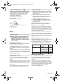
Funktionsbeschreibung
Bitte klappen Sie die Aufklappseite mit der Darstellung
des Elektrowerkzeugs auf, und lassen Sie diese Seite
aufgeklappt, während Sie die Betriebsanleitung lesen.
Bestimmungsgemäßer Gebrauch
Das Elektrowerkzeug ist bestimmt zum Trennen von
Blechen ohne Materialverformung und ist geeignet für
gerade Schnitte, Ausschnitte und enge Kurven.
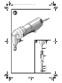
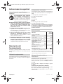
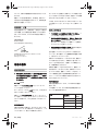
Abgebildete Komponenten
Die Nummerierung der abgebildeten Komponenten
bezieht sich auf die Darstellung des Elektrowerkzeu-
ges auf der Grafikseite.
1Ein-/Ausschalter
2Schraube für Matrizenhalter
3Stempel
4Matrizenhalter
5Matrize
6Gummiring der Rändelschraube
7Rändelschraube für Matrize
Abgebildetes oder beschriebenes Zubehör gehört
nicht zum Standard-Lieferumfang. Das vollständige
Zubehör finden Sie in unserem Zubehörprogramm.
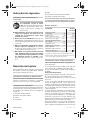
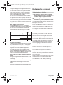
Technische Daten
Geräusch-/Vibrationsinformation
Messwerte für Geräusch ermittelt entsprechend
EN 60745.
Der A-bewertete Schalldruckpegel des Elektrowerk-
zeugs beträgt typischerweise 79 dB(A). Unsicherheit
K=3 dB.
Der Geräuschpegel beim Arbeiten kann 80 dB(A)
überschreiten.
Gehörschutz tragen!
Schwingungsgesamtwerte (Vektorsumme dreier Rich-
tungen) ermittelt entsprechend EN 60745:
Schwingungsemissionswert ah =9m/s
2, Unsicherheit
K < 3 m/s2.
Der in diesen Anweisungen angegebene Schwin-
gungspegel ist entsprechend einem in EN 60745
genormten Messverfahren gemessen worden und
kann für den Vergleich von Elektrowerkzeugen mitein-
ander verwendet werden. Er eignet sich auch für eine
vorläufige Einschätzung der Schwingungsbelastung.
Der angegebene Schwingungspegel repräsentiert die
hauptsächlichen Anwendungen des Elektrowerk-
zeugs. Wenn allerdings das Elektrowerkzeug für
andere Anwendungen, mit abweichenden Einsatz-
werkzeugen oder ungenügender Wartung eingesetzt
wird, kann der Schwingungspegel abweichen. Dies
kann die Schwingungsbelastung über den gesamten
Arbeitszeitraum deutlich erhöhen.
Für eine genaue Abschätzung der Schwingungsbe-
lastung sollten auch die Zeiten berücksichtigt werden,
in denen das Gerät abgeschaltet ist oder zwar läuft,
aber nicht tatsächlich im Einsatz ist. Dies kann die
Schwingungsbelastung über den gesamten Arbeits-
zeitraum deutlich reduzieren.
Legen Sie zusätzliche Sicherheitsmaßnahmen zum
Schutz des Bedieners vor der Wirkung von Schwin-
gungen fest wie zum Beispiel: Wartung von Elektro-
werkzeug und Einsatzwerkzeugen, Warmhalten der
Hände, Organisation der Arbeitsabläufe.
Nibbler TruTool
N 160 E
Nennaufnahmeleistung W350
Abgabeleistung W 160
Leerlaufhubzahl n0min-1 2200
Lasthubzahl min-1 1600
max. zu schneidende
Blechdicke* mm 1,6
Schneidspurbreite mm 5
kleinster Kurvenradius mm 40
Gewicht entsprechend
EPTA-Procedure 01/2003 kg 1,7
Schutzklasse /II
* bezogen auf Stahlbleche bis 400 N/mm2
Die Angaben gelten für eine Nennspannung [U] von 230 V.
Bei abweichenden Spannungen und in länderspezifischen
Ausführungen können diese Angaben variieren.
OBJ_BUCH-1198-001.book Page 4 Monday, August 2, 2010 1:46 PM

Deutsch | 53 609 929 B93 • 2.8.10
Konformitätserklärung
Wir erklären in alleiniger Verantwortung, dass das
unter „Technische Daten“ beschriebene Produkt mit
den folgenden Normen oder normativen Dokumenten
übereinstimmt: EN 60745 gemäß den Bestimmungen
der Richtlinien 2004/108/EG, 2006/42/EG.
Technische Unterlagen bei:
Friedrich Kilian
Geschäftsführer Entwicklung
TRUMPF Werkzeugmaschinen GmbH + Co. KG
D-71254 Ditzingen
Ditzingen, 29.01.2010
Betrieb
Inbetriebnahme
fBeachten Sie die Netzspannung! Die Span-
nung der Stromquelle muss mit den Anga-
ben auf dem Typenschild des Elektrowerk-
zeuges übereinstimmen. Mit 230 V gekenn-
zeichnete Elektrowerkzeuge können auch
an 220 V betrieben werden.
Ein-/Ausschalten
Zum Einschalten des Elektrowerkzeugs drücken Sie
den Ein-/Ausschalter 1.
Zum Arretieren des Ein-/Ausschalters 1 halten Sie
diesen gedrückt und schieben ihn nach hinten.
Zum Ausschalten des Elektrowerkzeugs lassen Sie
den Ein-/Ausschalter 1 los. Bei arretiertem Ein-/Aus-
schalter 1 drücken Sie diesen zuerst und lassen ihn
danach los.
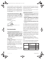
Schnittrichtung wechseln
Für den Wechsel der Schnittrichtung können Sie den
Matrizenhalter 4 in drei jeweils um 90° versetzte Posi-
tionen drehen. Die Schnittrichtung nach hinten (zum
Gehäuse hin) ist nicht möglich.
Zum Drehen des Matrizenhalters 4 lösen Sie die
Schraube 2 so weit, dass Sie den Matrizenhalter dre-
hen können. Drehen Sie ihn um 90° zur Längsachse
des Elektrowerkzeugs nach rechts oder links.
Achten Sie darauf, dass die Schraube 2 in die Boh-
rung am Matrizenhalter 4 eingreift. Ziehen Sie die
Schraube 2 fest.
Arbeitshinweise
fDas Elektrowerkzeug ist nicht für den Statio-
närbetrieb geeignet. Es darf z.B. nicht in einen
Schraubstock eingespannt oder auf einer Werk-
bank befestigt werden.
fTragen Sie Schutzhandschuhe bei der
Arbeit, und achten Sie besonders auf das
Netzkabel. An den geschnittenen Blechen ent-
stehen scharfe Grate, an denen Sie sich verletzen
oder das Netzkabel beschädigen können.
fVorsicht beim Umgang mit den Schneidspä-
nen. Die Späne haben scharfe Spitzen, an denen
Sie sich verletzen können.
Führen Sie das Elektrowerkzeug nur eingeschaltet
gegen das Werkstück. Halten Sie das Elektrowerk-
zeug immer senkrecht zur Blechoberfläche und ver-
kanten Sie es nicht.
Der Schnitt erfolgt während der Abwärtsbewegung
des Stempels. Führen Sie das Elektrowerkzeug
gleichmäßig und mit leichtem Schub in Schnittrich-
tung. Zu starker Vorschub verringert die Lebensdauer
der Einsatzwerkzeuge erheblich und kann dem Elek-
trowerkzeug schaden.
Das Elektrowerkzeug arbeitet ruhiger, wenn es beim
Schneiden leicht angehoben wird. Sollte der Stempel
beim Schneiden verklemmen, dann schalten Sie das
Elektrowerkzeug aus, schmieren Sie den Stempel
nach und entspannen Sie das Blech. Wenden Sie
keine Gewalt an, da sonst Stempel und Matrize
beschädigt werden.
Maximal zu schneidende Blechdicke
Die maximal zu schneidende Blechdicke dmax ist von
der Festigkeit des zu bearbeitenden Materials abhän-
gig.
Mit dem Elektrowerkzeug können Bleche bis zu fol-
gender Stärke gerade und verformungsfrei geschnit-
ten werden:
Material max. Festigkeit
[N/mm2]
dmax
[mm]
Stahl 400 1,6
600 1,0
800 0,7
Aluminium 200 2,0
OBJ_BUCH-1198-001.book Page 5 Monday, August 2, 2010 1:46 PM

6 | Deutsch 3 609 929 B93 • 2.8.10
Stempel schmieren/kühlen
Um die Lebensdauer des Stempels 3 zu verlängern,
sollten Sie ein Schmiermittel mit guter Kühlfunktion
(z.B. Schneidöl) verwenden.
Tragen Sie auf der Oberseite des Bleches entlang der
geplanten Schnittlinie eine Schmiermittelspur auf. Bei
längeren Arbeiten oder bei Arbeiten mit hohem Abrieb
(z.B. Schneiden von Aluminium) sollten Sie das Ein-
satzwerkzeug in regelmäßigen Abständen in einen
Behälter mit Schmiermittel tauchen.
Schneiden nach Anriss oder mit Schablone
Gerade Schnitte lassen sich leichter ausführen, wenn
Sie das Elektrowerkzeug an einem Lineal entlangfüh-
ren.
Konturen können durch Führen des Elektrowerkzeugs
entlang einer Schablone geschnitten werden.
Für Innenausschnitte ist eine Vorbohrung von 21 mm
Durchmesser notwendig.
Wartung und Service
Wartung und Reinigung
fZiehen Sie vor allen Arbeiten am Elektro-
werkzeug den Netzstecker aus der Steck-
dose.
fHalten Sie das Elektrowerkzeug und die Lüf-
tungsschlitze sauber, um gut und sicher zu
arbeiten.
Reinigen und ölen Sie alle 3 Betriebsstunden Stempel
3 und Matrize 5.
Wechseln Sie Stempel und Matrize bei Verschleiß
rechtzeitig, denn nur scharfe Werkzeuge bringen gute
Schnittleistung und schonen das Elektrowerkzeug.
Der Stempel 3 und die Matrize 5 dürfen nicht nachge-
schliffen werden.
Matrize wechseln
Schrauben Sie die Rändelschraube 7 aus dem Matri-
zenhalter 4. Entnehmen Sie die Matrize 5.
Reinigen Sie gegebenenfalls den Matrizenhalter 4.
Setzen Sie eine neue, gut geölte Matrize 5 in den
Matrizenhalter. Achten Sie dabei auf die Ausrichtung
der abgeflachten Seite.
Schrauben Sie die Rändelschraube 7 mit aufgesetz-
tem Gummiring 6 wieder ein. Ziehen Sie die Schraube
gegen den Widerstand des Gummirings gut fest.
Stempel wechseln
Lösen Sie die Schraube 2 und ziehen Sie den Matri-
zenhalter 4 vollständig aus dem Gehäuse.
Schieben Sie den Stempel 3 seitlich aus der Nut am
Matrizenhalter 4 und ziehen Sie ihn nach unten heraus.
Setzen Sie einen neuen, gut geölten Stempel 3 in die
Nut am Matrizenhalter 4 und richten Sie ihn mittig aus.
Schieben Sie den Matrizenhalter 4 vorsichtig über
den Stempel 3 in das Gehäuse zurück. Drehen Sie
den Matrizenhalter in eine der drei möglichen Positio-
nen (siehe „Schnittrichtung wechseln“, Seite 5). Zie-
hen Sie die Schraube 2 gut fest.
Zubehör
Matrize 5. . . . . . . . . . . . . . . . . . . . . . . . . . . . 0141714
Matrize für Blechdicke bis 1 mm . . . . . . . . 0931611
Stempel 3. . . . . . . . . . . . . . . . . . . . . . . . . . . 0117676
Verlängerung . . . . . . . . . . . . . . . . . . . . . . . . 0950316
Gewährleistung und Service
Für TRUMPF Elektro- und Druckluftwerkzeuge gilt
eine Haftungsfrist von 12 Monaten ab Rechnungsda-
tum. Schäden, die auf natürliche Abnützung, Überlas-
tung oder unsachgemäße Behandlung der Maschine
zurückzuführen sind, bleiben von der Gewährleistung
ausgeschlossen. Schäden, die durch Material- oder
Herstellerfehler entstanden sind, werden unentgelt-
lich durch Ersatzlieferung oder Reparatur beseitigt.
Beanstandungen können nur anerkannt werden,
wenn das Gerät unzerlegt an Ihre TRUMPF-Vertre-
tung gesandt wird.
Die Adresse zu Ihrem TRUMPF-Berater finden Sie
unter:
www.trumpf-powertools.com
Entsorgung
Elektrowerkzeuge, Zubehör und Verpackungen sollen
einer umweltgerechten Wiederverwertung zugeführt
werden.
Werfen Sie Elektrowerkzeuge nicht in den Hausmüll!
Nur für EU-Länder:
Gemäß der Europäischen Richtlinie
2002/96/EG über Elektro- und Elek-
tronik-Altgeräte und ihrer Umsetzung
in nationales Recht müssen nicht mehr
gebrauchsfähige Elektrowerkzeuge
getrennt gesammelt und einer umwelt-
gerechten Wiederverwertung zuge-
führt werden.
Änderungen vorbehalten.
OBJ_BUCH-1198-001.book Page 6 Monday, August 2, 2010 1:46 PM

English | 73 609 929 B93 • 2.8.10
Safety Notes
Safety Warnings for Nibblers
Read all safety warnings and all
instructions. Failure to follow the warn-
ings and instructions may result in elec-
tric shock, fire and/or serious injury.
fAdditionally, the general safety warnings
either in the enclosed leaflet or in the centre
of these operating instructions must also be
followed.
fSecure the workpiece. A workpiece clamped
with clamping devices or in a vice is held more
secure than by hand.
fAlways wait until the machine has come to a
complete stop before placing it down. The
tool insert can jam and lead to loss of control over
the power tool.
fNever use the machine with a damaged
cable. Do not touch the damaged cable and
pull the mains plug when the cable is dam-
aged while working. Damaged cables increase
the risk of an electric shock.
fProducts sold in GB only: Your product is fitted
with an BS 1363/A approved electric plug with
internal fuse (ASTA approved to BS 1362).
If the plug is not suitable for your socket outlets, it
should be cut off and an appropriate plug fitted in
its place by an authorised customer service agent.
The replacement plug should have the same fuse
rating as the original plug.
The severed plug must be disposed of to avoid a
possible shock hazard and should never be
inserted into a mains socket elsewhere.
Products sold in AUS and NZ only: Use a
residual current device (RCD) with a rated residual
current of 30 mA or less.
Functional Description
While reading the operating instructions, unfold the
graphics page for the machine and leave it open.
Intended Use
The machine is intended for cutting sheet metal with-
out deforming the material and is suitable for straight
cuts, cut-outs and narrow curves.
Product Features
The numbering of the product features refers to the
illustration of the machine on the graphics page.
1On/Off switch
2Die holder screw
3Punch
4Die holder
5Die
6Rubber ring for knurled screw
7Knurled screw for die
Accessories shown or described are not part of the
standard delivery scope of the product. A complete
overview of accessories can be found in our acces-
sories program.
Technical Data
Noise/Vibration Information
Measured sound values determined according to
EN 60745.
Typically the A-weighted sound pressure level of the
product is 79 dB(A). Uncertainty K=3 dB.
The noise level when working can exceed 80 dB(A).
Wear hearing protection!
Vibration total values (triax vector sum) determined
according to EN 60745:
Vibration emission value ah=9m/s
2, Uncertainty
K<3m/s
2.
The vibration emission level given in this information
sheet has been measured in accordance with a stand-
ardised test given in EN 60745 and may be used to
compare one tool with another. It may be used for a
preliminary assessment of exposure.
The declared vibration emission level represents the
main applications of the tool. However if the tool is
Nibbler TruTool
N 160 E
Rated power input W350
Output power W 160
Stroke rate at no load n0min-1 2200
Stroke speed under load min-1 1600
Max. steel sheet cutting
capacity* mm 1.6
Cutting width mm 5
Smallest curve radius mm 40
Weight according to
EPTA-Procedure 01/2003 kg 1.7
Protection class /II
* to 400 N/mm2 with reference to steel sheet
The values given are valid for a nominal voltage [U] of 230 V.
For different voltages and models for specific countries, these
values can vary.
OBJ_BUCH-1198-001.book Page 7 Monday, August 2, 2010 1:46 PM

8 | English 3 609 929 B93 • 2.8.10
used for different applications, with different accesso-
ries or poorly maintained, the vibration emission may
differ. This may significantly increase the exposure
level over the total working period.
An estimation of the level of exposure to vibration
should also take into account the times when the tool
is switched off or when it is running but not actually
doing the job. This may significantly reduce the expo-
sure level over the total working period.
Identify additional safety measures to protect the
operator from the effects of vibration such as: main-
tain the tool and the accessories, keep the hands
warm, organisation of work patterns.
Declaration of Conformity
We declare under our sole responsibility that the
product described under “Technical Data” is in con-
formity with the following standards or standardization
documents: EN 60745 according to the provisions of
the directives 2004/108/EC, 2006/42/EC.
Technical file at:
Friedrich Kilian
Geschäftsführer Entwicklung
TRUMPF Werkzeugmaschinen GmbH + Co. KG
D-71254 Ditzingen
Ditzingen, 29.01.2010
Operation
Starting Operation
fObserve correct mains voltage! The voltage
of the power source must agree with the
voltage specified on the nameplate of the
machine. Power tools marked with 230 V can
also be operated with 220 V.
Switching On and Off
To start the machine, press the On/Off switch 1.
For locking the On/Off switch 1 hold it down and
push it back.
To switch off the machine, release the On/Off switch
1. When the On/Off switch 1 is locked, press it first
and then release it.
Changing the Cutting Direction
For changing the cutting direction, the die holder 4
can be turned to three positions, each offset by 90°.
Cutting toward the rear (toward the housing of the
machine) is not possible.
For turning the die holder 4 loosen the screw 2 until
you can turn the die holder. Turn it 90 ° to the right or
the left in relation to the longitudinal axle of the power
tool.
Make sure that the screw 2 engages into the borehole
of the die holder 4. Tighten the screw 2.
Working Advice
fThe power tool is not suitable for stationary
operation. For example, it may not be clamped in
a vice or fastened on a workbench.
fWear protective gloves while working and
pay particular attention to the mains cable.
Sharp burrs develop at the cut steel sheet and can
cause injuries to the operator or damage the mains
cable.
fExercise caution when handling the cutting
chips. The chips have sharp tips that can cause
injuries.
Apply the machine to the workpiece only when
switched on. Always hold the machine vertical to the
surface of the steel sheet and do not tilt it.
The cut takes place during the downward motion of
the punch. Guide the machine evenly and with moder-
ate feed in the cutting direction. A high feed rate sig-
nificantly reduces the service life of the cutting tools
and can damage the machine.
The machine operates more quietly when it is raised
slightly during cutting. If the punch should become
wedged during cutting, switch the machine off, relu-
bricate the punch and release the tension of the steel
sheet. Do not exert force, otherwise the punch and the
die will become damaged.
Maximum Steel Sheet Cutting Capacity
The maximum steel sheet cutting capacity dmax
depends on the strength properties of the material to
be cut.
The machine allows for straight and deformation-free
cutting of metal sheets to the following thicknesses:
Material Max. strength property
[N/mm2]
dmax
[mm]
Steel 400 1.6
600 1.0
800 0.7
Aluminium 200 2.0
OBJ_BUCH-1198-001.book Page 8 Monday, August 2, 2010 1:46 PM

English | 93 609 929 B93 • 2.8.10
Lubricating/Cooling the Punch
To extend the service life of the punch 3, a lubricating
agent with good cooling properties (e.g. cutting oil)
should be used.
Apply a trail of lubricant beads onto the top side of the
metal sheet alongside the intended cutting line. For
long periods of continual use or for work with high fric-
tional wear (e.g. when cutting aluminium), the cutting
head should be immersed into a container with lubri-
cant in regular intervals.
Cutting along a Cutting Mark or with a Guide
Straight cuts are carried out easier when the machine
is guided alongside a rule.
Contours can be cut by guiding the machine along a
template.
For inside cuts, pre-drilling a hole with a diameter of
21 mm is necessary.
Maintenance and Service
Maintenance and Cleaning
fBefore any work on the machine itself, pull
the mains plug.
fFor safe and proper working, always keep
the machine and ventilation slots clean.
Clean and lubricate the punch 3 and die 5 every
3 operating hours.
Change the punch and die in good time when worn.
Only sharp tools produce a good cutting quality and
make the machine last longer.
The punch 3 and the die 5 may not be reground.
Changing the Die
Unscrew the knurled screw 7 of the die holder 4. Take
out the die 5.
Il necessary, clean the die holder 4.
Put a new, well greased die 5 into the die holder. Pay
attention to the alignment of the flat side.
Tighten the knurled screw 7 again, the rubber ring
placed onto it 6. Tighten the screw against the resist-
ance of the rubber ring.
Changing the Punch
Loosen the screw 2 and pull the die holder und 4 com-
pletely out of the housing.
Push the punch 3 laterally out of the slot in the die
holder 4 and pull it down and out.
Place a new, well greased punch 3 into the slot in the
die holder 4 and align it centrally.
Push the die holder 4 with caution over the punch 3
back into the housing. Turn the die holder into one of
the three possible positions (see “Changing the Cut-
ting Direction”, page 8). Tighten the screw 2.
Accessories
Die 5. . . . . . . . . . . . . . . . . . . . . . . . . . . . . . . 0141714
Die for sheet thickness up to 1 mm . . . . . . 0931611
Punch 3 . . . . . . . . . . . . . . . . . . . . . . . . . . . . 0117676
Extension . . . . . . . . . . . . . . . . . . . . . . . . . . . 0950316
Warranty and Service
For TRUMPF power and pneumatic tools, a liability
period of 12 months applies from the invoice date on.
Damage attributable to normal wear, overloading or
improper handling of the machine will be excluded
from the warranty. Damage due to material or manu-
facturing defects will be corrected free-of-charge by
replacement or repair. Claims can only be accepted
when the machine is sent undisassembled to your
TRUMPF Service Centre.
The address of your TRUMPF representative can be
found under:
www.trumpf-powertools.com
Disposal
The machine, accessories and packaging should be
sorted for environmental-friendly recycling.
Do not dispose of power tools into household waste!
Only for EC countries:
According to the European Guideline
2002/96/EC for Waste Electrical and
Electronic Equipment and its imple-
mentation into national right, power
tools that are no longer usable must be
collected separately and disposed of
in an environmentally correct manner.
Subject to change without notice.
OBJ_BUCH-1198-001.book Page 9 Monday, August 2, 2010 1:46 PM

10 | Français 3 609 929 B93 • 2.8.10
Avertissements de sécurité
Avertissements de sécurité pour les
grignoteuses à tôle
Il est impératif de lire toutes les con-
signes de sécurité et toutes les ins-
tructions. Le non-respect des avertisse-
ments et instructions indiqués ci-après
peut conduire à une électrocution, un in-
cendie et/ou de graves blessures.
fRespecter également les indications généra-
les de sécurité se trouvant dans le cahier ci-
joint ou au milieu de la présente notice d’uti-
lisation.
fBloquer la pièce à travailler. Une pièce à tra-
vailler serrée par des dispositifs de serrage appro-
priés ou dans un étau est fixée de manière plus
sûre que tenue dans les mains.
fAvant de déposer l’outil électroportatif,
attendre que celui-ci soit complètement à
l’arrêt. L’outil risque de se coincer, ce qui entraîne-
rait une perte de contrôle de l’outil électroportatif.
fNe jamais utiliser un outil électroportatif
dont le câble est endommagé. Ne pas tou-
cher à un câble endommagé et retirer la
fiche du câble d’alimentation de la prise de
courant, au cas où le câble aurait été endom-
magé lors du travail. Un câble endommagé aug-
mente le risque de choc électrique.
Description du
fonctionnement
Dépliez le volet sur lequel l’appareil est représenté de
manière graphique. Laissez le volet déplié pendant la
lecture de la présente notice d’utilisation.
Utilisation conforme
L’outil électroportatif est conçu pour le découpage de
tôles sans déformation du matériau, et il est approprié
pour effectuer des coupes droites, des découpes
ainsi que des courbes à très faible rayon.
Eléments de l’appareil
La numérotation des éléments de l’appareil se réfère
à la représentation de l’outil électroportatif sur la page
graphique.
1Interrupteur Marche/Arrêt
2Vis pour porte-matrice
3Poinçon
4Porte-matrice
5Matrice
6Rondelle en caoutchouc de la vis moletée
7Vis moletée pour matrice
Les accessoires décrits ou illustrés ne sont pas tous
compris dans la fourniture. Vous trouverez les acces-
soires complets dans notre programme d’accessoires.
Caractéristiques techniques
Niveau sonore et vibrations
Valeurs de mesure du niveau sonore relevées confor-
mément à la norme EN 60745.
Les mesures réelles (A) du niveau de pression acous-
tique de l’appareil sont de 79 dB(A). Incertitude
K=3 dB.
Lors du travail, le niveau sonore peut dépasser
80 dB(A).
Porter une protection acoustique !
Valeurs totales des vibrations (somme vectorielle des
trois axes directionnels) relevées conformément à la
norme EN 60745 :
Valeur d’émission vibratoire ah=9m/s
2, incertitude
K<3m/s
2.
Grignoteuse TruTool
N 160 E
Puissance nominale absorbée W350
Puissance utile débitée W 160
Nombre de courses à vide n0tr/min 2200
Nombre de courses sous charge tr/min 1600
Epaisseur de tôle max. à couper* mm 1,6
Largeur de coupe mm 5
Rayon minimal pour découpes
curvilignes mm 40
Poids suivant
EPTA-Procedure 01/2003 kg 1,7
Classe de protection /II
* par rapport aux tôles d’acier jusqu’à 400 N/mm2
Ces indications sont valables pour une tension nominale de
[U] 230 V. Ces indications peuvent varier pour des tensions
plus basses ainsi que pour des versions spécifiques à cer-
tains pays.
OBJ_BUCH-1198-001.book Page 10 Monday, August 2, 2010 1:46 PM

Français | 113 609 929 B93 • 2.8.10
Le niveau d’oscillation indiqué dans ces instructions
d’utilisation a été mesuré conformément à la norme
EN 60745 et peut être utilisé pour une comparaison
d’outils électroportatifs. Il est également approprié
pour une estimation préliminaire de la charge vibra-
toire.
Le niveau d’oscillation correspond aux utilisations
principales de l’outil électroportatif. Si l’outil électrique
est cependant utilisé pour d’autres applications, avec
d’autres outils de travail ou avec un entretien non
approprié, le niveau d’oscillation peut être différent.
Ceci peut augmenter considérablement la charge
vibratoire pendant toute la durée de travail.
Pour une estimation précise de la charge vibratoire, il
est recommandé de prendre aussi en considération
les périodes pendant lesquelles l’appareil est éteint
ou en fonctionnement, mais pas vraiment utilisé. Ceci
peut réduire considérablement la charge vibratoire
pendant toute la durée de travail.
Déterminez des mesures de protection supplémentai-
res pour protéger l’utilisateur des effets de vibrations,
telles que par exemple : entretien de l’outil électrique
et des outils de travail, maintenir les mains chaudes,
organisation judicieuse des opérations de travail.
Déclaration de conformité
Nous déclarons sous notre propre responsabilité que
le produit décrit sous « Caractéristiques techniques »
est en conformité avec les normes ou documents nor-
matifs suivants : EN 60745 conformément aux termes
des réglementations en vigueur 2004/108/CE,
2006/42/CE.
Dossier technique auprès de :
Friedrich Kilian
Geschäftsführer Entwicklung
TRUMPF Werkzeugmaschinen GmbH + Co. KG
D-71254 Ditzingen
Ditzingen, 29.01.2010
Mise en marche
Mise en service
fTenez compte de la tension du réseau ! La
tension de la source de courant doit corres-
pondre aux indications se trouvant sur la
plaque signalétique de l’outil électroportatif.
Les outils électroportatifs marqués 230 V
peuvent également fonctionner sur 220 V.
Mise en Marche/Arrêt
Pour mettre en marche l’outil électroportatif, appuyez
sur l’interrupteur Marche/Arrêt 1.
Pour bloquer l’interrupteur Marche/Arrêt 1, maintenez
celui-ci appuyé et poussez-le vers l’arrière.
Pour arrêter l’outil électroportatif, relâchez l’interrup-
teur Marche/Arrêt 1. Quand l’interrupteur Marche/Arrêt
1 est bloqué, appuyez d’abord sur l’interrupteur Mar-
che/Arrêt, et relâchez-le ensuite.
Changement du sens de la coupe
Pour changer le sens de la coupe, il est possible de
tourner le porte-matrice 4 dans trois positions, chacune
décalée de 90°. Un sens de coupe vers l’arrière (en
direction du carter) n’est pas possible.
Pour tourner le porte-matrice 4, desserrez la vis 2
jusqu’à ce qu’il soit possible de tourner le porte-
matrice. Tournez-le de 90° par rapport à l’axe longitudi-
nal de l’outil électroportatif vers la droite ou la gauche.
Veillez à ce que la vis 2 prenne dans l’alésage du porte-
matrice 4. Resserrez la vis 2.
Instructions d’utilisation
fL’outil électroportatif n’est pas conçu pour
une utilisation stationnaire. Ne ne le serrez
pas dans un étau par ex., et ne l’attachez pas sur
un établi.
fPorter des gants de protection pendant le
travail et veiller surtout au câble de secteur.
Sur les tôles coupées, il y a des arêtes aiguës qui
risquent de vous blesser ou d’endommager le
câble de secteur.
fPrudence lors du maniement de copeaux.
Les copeaux ont des pointes tranchantes sur les-
quelles on peut se blesser.
Ne guidez l’outil électroportatif contre la pièce à tra-
vailler que quand l’appareil est en marche. Tenez tou-
jours l’outil électroportatif verticalement par rapport à
la surface de la tôle et ne le coincez pas.
Le processus de coupe s’effectue pendant la des-
cente du poinçon. Guidez l’outil électroportatif de
façon régulière et en effectuant une avance modérée
dans le sens de la coupe. Une avance trop forte réduit
considérablement la durée de vie des outils électro-
portatifs et peut endommager l’outil électroportatif.
OBJ_BUCH-1198-001.book Page 11 Monday, August 2, 2010 1:46 PM

12 | Français 3 609 929 B93 • 2.8.10
L’outil électroportatif travaille de façon plus calme
quand il est soulevé un peu pendant la coupe. Au cas
où le poinçon se coincerait pendant la coupe, étei-
gnez l’outil électroportatif, regraissez le poinçon et
détendez la tôle. Ne forcez pas pour ne pas endom-
mager le poinçon et la matrice.
Epaisseur de tôle max. à couper
L’épaisseur de tôle max. à couper dmax dépend de la
solidité du matériau à travailler.
Avec l’outil électroportatif, il est possible de couper
des tôles droites sans les déformer jusqu’à l’épaisseur
suivante :
Graisser/refroidir le poinçon
Afin de prolonger la durée de vie du poinçon 3, il est
recommandé d’utiliser un lubrifiant disposant d’une
bonne fonction de refroidissement (par ex. huile de
coupe).
Appliquez une trace de lubrifiant sur la surface de la
tôle le long de la coupe prévue. Lors de travaux plus
longs ou de travaux avec un grand enlèvement de
matière (par ex. coupe d’aluminium), immergez l’outil
de travail régulièrement dans un réservoir contenant
du lubrifiant.
Couper après traçage ou avec gabarit
Les coupes droites peuvent être effectuées plus faci-
lement si vous guidez l’outil électroportatif le long
d’une règle.
Les contours peuvent être coupés en guidant l’outil
électroportatif le long d’un gabarit.
Les découpes internes nécessitent un préperçage de
21 mm de diamètre.
Entretien et Service
Après-Vente
Nettoyage et entretien
fAvant d’effectuer des travaux sur l’outil élec-
troportatif, retirez la fiche de la prise de cou-
rant.
fVeillez à ce que l’outil électroportatif ainsi
que les ouïes de ventilation soient toujours
propres afin d’obtenir un travail impeccable
et sûr.
Toutes les 3 heures de service, nettoyer et graisser le
poinçon 3 et la matrice 5.
Remplacer à temps le poinçon et la matrice dans le
cas d’usure, parce que seuls des outils aigus ont un
effet de coupe élevé et ménagent l’outil électroportatif.
Ni le poinçon 3 ni la matrice 5 ne doivent être réaffûtés.
Changement de la matrice
Dévissez la vis moletée 7 du porte-matrice 4. Retirez
la matrice 5.
Si nécessaire, nettoyez le porte-matrice 4.
Montez une nouvelle matrice, bien huilée 5 dans le
porte-matrice. Veillez à l’alignement du côté plat.
Resserrez la vis moletée 7, la rondelle en caoutchouc
6 montée. Serrez la vis contre la résistance de la ron-
delle en caoutchouc.
Changement du poinçon
Desserrez la vis 2 et sortez le porte-matrice 4 complè-
tement du carter.
Poussez le poinçon 3 latéralement pour le sortir de la
rainure du porte-matrice 4 et retirez-le par le bas.
Montez un poinçon neuf 3, bien huilé, dans la rainure
du porte-matrice 4 et alignez-le de sorte qu’il soit au
centre.
Poussez le porte-matrice 4 avec précaution par-des-
sus le poinçon 3 dans le carter. Tournez le porte-
matrice pour le mettre dans une des trois positions
possibles (voir « Changement du sens de la coupe »,
page 11). Resserrez la vis 2.
Accessoires
Matrice 5. . . . . . . . . . . . . . . . . . . . . . . . . . . . 0141714
Matrice pour une profondeur
de tôle jusqu’à 1 mm . . . . . . . . . . . . . . . . . . 0931611
Poinçon 3 . . . . . . . . . . . . . . . . . . . . . . . . . . . 0117676
Rallonge . . . . . . . . . . . . . . . . . . . . . . . . . . . . 0950316
Matériau Solidité max.
[N/mm2]
dmax
[mm]
Acier 400 1,6
600 1,0
800 0,7
Aluminium 200 2,0
OBJ_BUCH-1198-001.book Page 12 Monday, August 2, 2010 1:46 PM

Français | 133 609 929 B93 • 2.8.10
Garantie et Service Après-Vente
Un délai de garantie de 12 mois à compter de la date
de la facture s’applique pour les outils électroportatifs
et pneumatiques TRUMPF. Cette garantie corres-
pond à un emploi normal de l’outil et exclut les dom-
mages dus à un mauvais usage, une surcharge ou à
l’usure normale. En cas de dommages causés par des
défauts matériels ou des fautes du fabricant, une
livraison de remplacement ou une réparation de
l’appareil seront assurées sans frais. Les réclamations
ne peuvent être reconnues que si vous retournez
l’appareil non démonté à votre détaillant TRUMPF.
Vous trouverez l’adresse de votre conseiller TRUMPF
sous :
www.trumpf-powertools.com
Elimination des déchets
Les outils électroportatifs, ainsi que leurs accessoires
et emballages, doivent pouvoir suivre chacun une voie
de recyclage appropriée.
Ne jetez pas les outils électroportatifs avec les ordu-
res ménagères !
Seulement pour les pays de l’Union
Européenne :
Conformément à la directive euro-
péenne 2002/96/CE relative aux
déchets d’équipements électriques et
électroniques et sa mise en vigueur
conformément aux législations natio-
nales, les outils électroportatifs dont
on ne peut plus se servir doivent être isolés et suivre
une voie de recyclage appropriée.
Sous réserve de modifications.
OBJ_BUCH-1198-001.book Page 13 Monday, August 2, 2010 1:46 PM

14 | Español 3 609 929 B93 • 2.8.10
Instrucciones de seguridad
Instrucciones de seguridad para
roedoras
Lea íntegramente estas adverten-
cias de peligro e instrucciones. En
caso de no atenerse a las advertencias
de peligro e instrucciones siguientes,
ello puede ocasionar una descarga eléc-
trica, un incendio y/o lesión grave.
fAdicionalmente deberán seguirse las indica-
ciones de seguridad generales incluidas en
el cuaderno que o bien se adjunta por sepa-
rado, o que va cosido en el centro de estas
instrucciones de uso.
fAsegure la pieza de trabajo. Una pieza de tra-
bajo fijada con unos dispositivos de sujeción, o en
un tornillo de banco, se mantiene sujeta de forma
mucho más segura que con la mano.
fAntes de depositarla, esperar a que se haya
detenido la herramienta eléctrica. El útil
puede engancharse y hacerle perder el control
sobre la herramienta eléctrica.
fNo utilice la herramienta eléctrica si el cable
está dañado. No toque un cable dañado, y
desconecte el enchufe de la red, si el cable
se daña durante el trabajo. Un cable dañado
comporta un mayor riesgo de electrocución.
Descripción del
funcionamiento
Despliegue y mantenga abierta la solapa con la ima-
gen del aparato mientras lee las instrucciones de
manejo.
Utilización reglamentaria
La herramienta eléctrica ha sido diseñada para efec-
tuar cortes rectos, en curva, y recortes en chapa, sin
deformarla.
Componentes principales
La numeración de los componentes está referida a la
imagen de la herramienta eléctrica en la página ilus-
trada.
1Interruptor de conexión/desconexión
2Tornillo para portamatriz
3Punzón
4Portamatriz
5Matriz
6Anillo de goma del tornillo moleteado
7Tornillo moleteado de matriz
Los accesorios descritos e ilustrados no corresponden
al material que se adjunta de serie. La gama completa
de accesorios opcionales se detalla en nuestro pro-
grama de accesorios.
Datos técnicos
Información sobre ruidos y
vibraciones
Ruido determinado según EN 60745.
El nivel de presión sonora típico del aparato, determi-
nado con un filtro A, es de 79 dB(A). Tolerancia
K=3 dB.
El nivel de ruido al trabajar puede llegar a superar
80 dB(A).
¡Colocarse unos protectores auditivos!
Nivel total de vibraciones (suma vectorial de tres
direcciones) determinado según EN 60745:
Valor de vibraciones generadas ah=9m/s
2, toleran-
cia K < 3 m/s2.
Roedora TruTool
N 160 E
Potencia absorbida
nominal W350
Potencia útil W 160
Nº de carreras en vacío n0min-1 2200
Nº de carreras bajo carga min-1 1600
Capacidad de corte en
chapa, máx.* mm 1,6
Anchura de la franja de
corte mm 5
Radio de corte, mín. mm 40
Peso según
EPTA-Procedure 01/2003 kg 1,7
Clase de protección /II
* en chapas de acero de hasta 400 N/mm2
Estos datos son válidos para una tensión nominal de [U]
230 V. Los valores pueden variar para otras tensiones y en
ejecuciones específicas para ciertos países.
OBJ_BUCH-1198-001.book Page 14 Monday, August 2, 2010 1:46 PM

Español | 153 609 929 B93 • 2.8.10
El nivel de vibraciones indicado en estas instruccio-
nes ha sido determinado según el procedimiento de
medición fijado en la norma EN 60745 y puede servir
como base de comparación con otras herramientas
eléctricas. También es adecuado para estimar provi-
sionalmente la solicitación experimentada por las
vibraciones.
El nivel de vibraciones indicado ha sido determinado
para las aplicaciones principales de la herramienta
eléctrica. Por ello, el nivel de vibraciones puede ser
diferente si la herramienta eléctrica se utiliza para
otras aplicaciones, con útiles diferentes, o si el man-
tenimiento de la misma fuese deficiente. Ello puede
suponer un aumento drástico de la solicitación por
vibraciones durante el tiempo total de trabajo.
Para determinar con exactitud la solicitación experi-
mentada por las vibraciones, es necesario considerar
también aquellos tiempos en los que el aparato esté
desconectado, o bien, esté en funcionamiento, pero
sin ser utilizado realmente. Ello puede suponer una
disminución drástica de la solicitación por vibraciones
durante el tiempo total de trabajo.
Fije unas medidas de seguridad adicionales para pro-
teger al usuario de los efectos por vibraciones, como
por ejemplo: Mantenimiento de la herramienta eléc-
trica y de los útiles, conservar calientes las manos,
organización de las secuencias de trabajo.
Declaración de conformidad
Declaramos bajo nuestra responsabilidad, que el pro-
ducto descrito bajo “Datos técnicos” está en confor-
midad con las normas o documentos normalizados
siguientes: EN 60745 de acuerdo con las disposicio-
nes en las directivas 2004/108/CE, 2006/42/CE.
Expediente técnico en:
Friedrich Kilian
Geschäftsführer Entwicklung
TRUMPF Werkzeugmaschinen GmbH + Co. KG
D-71254 Ditzingen
Ditzingen, 29.01.2010
Operación
Puesta en marcha
f¡Observe la tensión de red! La tensión de ali-
mentación deberá coincidir con las indica-
ciones en la placa de características de la
herramienta eléctrica. Las herramientas
eléctricas marcadas con 230 V pueden fun-
cionar también a 220 V.
Conexión/desconexión
Para conectar la herramienta eléctrica presionar el
interruptor de conexión/desconexión 1.
Para enclavar el interruptor de conexión/desco-
nexión 1 manténgalo accionado y empújelo hacia
atrás.
Para desconectar la herramienta eléctrica suelte el
interruptor de conexión/desconexión 1. Si el interrup-
tor de conexión/desconexión 1 estuviese enclavado,
apriételo primero y suéltelo a continuación.
Cambio del sentido de corte
Para cambiar el sentido de corte, es posible girar el
portamatriz 4 a tres posiciones diferentes en saltos de
90°. No es posible ajustar el sentido de corte hacia
atrás (en dirección a la carcasa).
Para girar el portamatriz 4, afloje el tornillo 2 lo sufi-
ciente nada más para poder girar el portamatriz.
Gírelo 90° hacia la derecha o izquierda respecto al
eje longitudinal de la herramienta eléctrica.
Preste atención a que el tornillo 2 penetre en el tala-
dro del portamatriz 4. Apriete el tornillo 2.
Instrucciones para la operación
fLa herramienta eléctrica no es apropiada
para un uso estacionario. No deberá sujetarse,
p.ej., en un tornillo de banco ni fijarse a un banco
de trabajo.
fColóquese unos guantes de protección al
trabajar, y preste especial atención a no
dañar el cable de red. Al cortar chapa se forman
rebabas cortantes que le pueden dañar a Ud. y al
cable de red.
fTenga cuidado al tocar las virutas. Las virutas
tienen unas puntas afiladas que pueden lesionarle.
Solamente aproxime la herramienta eléctrica en fun-
cionamiento contra la pieza de trabajo. Siempre man-
tenga la herramienta eléctrica perpendicular a la
superficie de la chapa, sin ladearla.
OBJ_BUCH-1198-001.book Page 15 Monday, August 2, 2010 1:46 PM

16 | Español 3 609 929 B93 • 2.8.10
El corte se realiza durante el movimiento de descenso
del punzón. Guíe la herramienta eléctrica uniforme-
mente, ejerciendo una leve fuerza de empuje en la
dirección de corte. Una fuerza de avance excesiva
reduce fuertemente la duración de los útiles y puede
dañar a la herramienta eléctrica.
La herramienta eléctrica trabaja de forma más tran-
quila si se eleva ligeramente al cortar. En caso de
atascarse el punzón durante el proceso de corte, des-
conecte la herramienta eléctrica, lubrique el punzón, y
enderece la chapa. No proceda con brusquedad, ya
que podría deteriorar el punzón o la matriz.
Capacidad máxima de corte en chapa
El grosor máximo de chapa dmax que puede cortarse,
depende de la resistencia del material a trabajar.
Con la herramienta eléctrica pueden realizarse cortes
rectos, sin deformarla, chapa del grosor siguiente:
Lubricación/refrigeración del punzón
Para obtener una vida útil prolongada del punzón 3 se
recomienda emplear un lubricante con unas buenas
propiedades refrigerantes (p.ej. aceite de corte).
Aplique una franja de lubricante sobre la cara superior
de la chapa, a lo largo de la trayectoria de corte pre-
vista. Al trabajar prolongadamente, o en trabajos con
fuerte abrasión (p.ej. al cortar aluminio), se reco-
mienda sumergir periódicamente los útiles de corte
en un recipiente con lubricante.
Corte según trazo o con plantilla
Los cortes rectos se realizan más fácilmente guiando
la herramienta eléctrica a lo largo de una regla.
Es posible cortar contornos guiando la herramienta
eléctrica a lo largo de una plantilla.
Para efectuar recortes interiores se requiere efectuar
primero un taladro de 21 mm.
Mantenimiento y servicio
Mantenimiento y limpieza
fAntes de cualquier manipulación en la herra-
mienta eléctrica, sacar el enchufe de red de
la toma de corriente.
fMantenga limpia la herramienta eléctrica y
las rejillas de refrigeración para trabajar con
eficacia y seguridad.
Limpie y aceite cada tres horas de servicio el punzón
3 y la matriz 5.
Sustituya con suficiente antelación un punzón y matriz
desgastados para mantener un buen rendimiento de
corte y cuidar la herramienta eléctrica.
El punzón 3 y la matriz 5 no deberán reafilarse.
Cambio de la matriz
Desenrosque completamente el tornillo moleteado 7
del portamatriz 4. Retire la matriz 5.
Si fuese preciso, limpie el portamatriz 4.
Monte una matriz 5 nueva, bien aceitada, en el porta-
matriz. Al realizar esto observe que quede correcta-
mente orientado el lado con el fresado plano.
Enrosque nuevamente el tornillo moleteado 7 tras
haber montado en el mismo el anillo de goma 6.
Apriete el tornillo hasta asentarlo firmemente contra el
anillo de goma.
Cambio del punzón
Afloje el tornillo 2 y retire completamente el portama-
triz 4 de la carcasa.
Empuje lateralmente el punzón 3 fuera de la ranura del
portamatriz 4 y sáquelo hacia abajo.
Inserte un punzón 3 nuevo y bien aceitado en la ranura
del portamatriz 4 cuidando que quede bien centrado.
Vuelva a insertar el portamatriz 4 en la carcasa desli-
zándolo cuidadosamente sobre el punzón 3. Gire el
portamatriz a una de las tres posiciones posibles (ver
“Cambio del sentido de corte”, página 15). Apriete fir-
memente el tornillo 2.
Accesorios especiales
Matriz 5. . . . . . . . . . . . . . . . . . . . . . . . . . . . . 0141714
Matriz para un grosor de chapa
hasta 1 mm. . . . . . . . . . . . . . . . . . . . . . . . . . 0931611
Punzón 3. . . . . . . . . . . . . . . . . . . . . . . . . . . . 0117676
Prolongador . . . . . . . . . . . . . . . . . . . . . . . . . 0950316
Material Resistencia máx.
[N/mm2]
dmax
[mm]
Acero 400 1,6
600 1,0
800 0,7
Aluminio 200 2,0
OBJ_BUCH-1198-001.book Page 16 Monday, August 2, 2010 1:46 PM

Español | 173 609 929 B93 • 2.8.10
Garantía y servicio
Para las herramientas eléctricas y neumáticas
TRUMPF concedemos una garantía de 12 meses a
partir de la fecha de la factura. No quedan cubiertos
por la garantía los daños ocasionados por desgaste
natural, sobrecarga o manejo inadecuado de la
máquina. Las averías debidas a defectos de material
o fabricación serán subsanadas mediante reposición
o reparación del aparato, según se estime conve-
niente Las reclamaciones solamente podrán tenerse
en cuenta si Ud. envía el aparato, sin desmontar, a su
representante TRUMPF habitual.
La dirección de la persona de TRUMPF encargada de
asesorarle la encuentra Ud. bajo:
www.trumpf-powertools.com
Eliminación
Recomendamos que las herramientas eléctricas,
accesorios y embalajes sean sometidos a un proceso
de recuperación que respete el medio ambiente.
¡No arroje las herramientas eléctricas a la basura!
Sólo para los países de la UE:
Conforme a la Directiva Europea
2002/96/CE sobre aparatos eléctri-
cos y electrónicos inservibles, tras su
transposición en ley nacional, deberán
acumularse por separado las herra-
mientas eléctricas para ser sometidas
a un reciclaje ecológico.
Reservado el derecho de modificación.
OBJ_BUCH-1198-001.book Page 17 Monday, August 2, 2010 1:46 PM

18 | Português 3 609 929 B93 • 2.8.10
Indicações de segurança
Indicações de segurança para
cisalhador
Devem ser lidas todas as indicações
de advertência e todas as instru-
ções. O desrespeito das advertências e
instruções apresentadas abaixo pode
causar choque eléctrico, incêndio e/ou
graves lesões.
fAdicionalmente devem ser seguidas as indi-
cações de segurança em anexo ou as do
caderno que se encontra no centro desta
instrução de serviço.
fFixar a peça a ser trabalhada. Uma peça a ser
trabalhada fixa com dispositivos de aperto ou com
torno de bancada está mais firme do que segurada
com a mão.
fEspere a ferramenta eléctrica parar comple-
tamente, antes de depositá-la. A ferramenta
de aplicação pode emperrar e levar à perda de
controlo sobre a ferramenta eléctrica.
fNão utilizar a ferramenta eléctrica com um
cabo danificado. Não tocar no cabo danifi-
cado nem puxar a ficha da tomada, se o cabo
for danificado durante o trabalho. Cabos
danificados aumentam o risco de um choque eléc-
trico.
Descrição de funções
Abrir a página basculante contendo a apresentação
do aparelho, e deixar esta página aberta enquanto
estiver lendo a instrução de serviço.
Utilização conforme as disposições
A ferramenta eléctrica é destinada para cortar chapas
metálicas, sem deformar o material, e é apropriada
para cortes rectos, recortes e curvas apertadas.
Componentes ilustrados
A numeração dos componentes ilustrados refere-se à
apresentação da ferramenta eléctrica na página de
esquemas.
1Interruptor de ligar-desligar
2Parafuso para porta-matrizes
3Punção
4Porta-matriz
5Matriz
6Anel de borracha do parafuso serrilhado
7Parafuso serrilhado para a matriz
Acessórios apresentados ou descritos não pertencem
ao volume de fornecimento padrão. Todos os acessó-
rios encontram-se no nosso programa de acessórios.
Dados técnicos
Informação sobre ruídos/vibrações
Valores de medição para ruídos, averiguados con-
forme EN 60745.
O nível de pressão acústica avaliado como A do apa-
relho é tipicamente 79 dB(A). Incerteza K=3 dB.
O nível de ruído durante o trabalho pode ultrapassar
80 dB(A).
Usar protecção auricular!
Valores totais de vibração (soma dos vectores de três
direcções) determinados conforme EN 60745:
valor de emissão de vibrações ah =9m/s
2, incerteza
K < 3 m/s2.
O nível de oscilações indicado nestas instruções de
serviço foi medido de acordo com um processo de
medição normalizado pela norma EN 60745 e pode
ser utilizado para a comparação de aparelhos. Ele tam-
bém é apropriado para uma avaliação provisória da
carga de vibrações.
O nível de vibrações indicado representa as aplicações
principais da ferramenta eléctrica. Se a ferramenta
eléctrica for utilizada para outras aplicações, com
outras ferramentas de trabalho ou com manutenção
insuficiente, é possível que o nível de vibrações seja
diferente. Isto pode aumentar sensivelmente a carga de
vibrações para o período completo de trabalho.
Para uma estimação exacta da carga de vibrações,
também deveriam ser considerados os períodos nos
quais o aparelho está desligado ou funciona, mas não
Cisalhador TruTool
N 160 E
Potência nominal
consumida W350
Potência útil W 160
N° de cursos em vazio n0min-1 2200
N° de cursos em carga min-1 1600
máx. espessura da chapa a
ser cortada* mm 1,6
Largura do corte mm 5
mínimo raio de curvatura mm 40
Peso conforme
EPTA-Procedure 01/2003 kg 1,7
Classe de protecção /II
* relativos a chapas de aço de até 400 N/mm2
As indicações valem para tensões nominais [U] de 230 V.
Estas indicações podem variar dependendo de tensões infe-
riores e dos modelos específicos dos países.
OBJ_BUCH-1198-001.book Page 18 Monday, August 2, 2010 1:46 PM

Português | 193 609 929 B93 • 2.8.10
está sendo utilizado. Isto pode reduzir a carga de
vibrações durante o completo período de trabalho.
Além disso também deverão ser estipuladas medidas
de segurança para proteger o operador contra o
efeito de vibrações, como por exemplo: Manutenção
de ferramentas eléctricas e de ferramentas de traba-
lho, manter as mãos quentes e organização dos pro-
cessos de trabalho.
Declaração de conformidade
Declaramos sob nossa exclusiva responsabilidade
que o produto descrito em “Dados técnicos” cumpre
as seguintes normas ou documentos normativos:
EN 60745 conforme as disposições das directivas
2004/108/CE, 2006/42/CE.
Processo técnico em:
Friedrich Kilian
Geschäftsführer Entwicklung
TRUMPF Werkzeugmaschinen GmbH + Co. KG
D-71254 Ditzingen
Ditzingen, 29.01.2010
Funcionamento
Colocação em funcionamento
fObservar a tensão de rede! A tensão da
fonte de corrente deve coincidir com a indi-
cada na chapa de identificação da ferra-
menta eléctrica. Ferramentas eléctricas
marcadas para 230 V também podem ser
operadas com 220 V.
Ligar e desligar
Para ligar a ferramenta eléctrica, deverá pressionar o
interruptor de ligar-desligar 1.
Para bloquear o interruptor de ligar-desligar 1
deverá mantê-lo premido e empurrá-lo para trás.
Para desligar a ferramenta eléctrica, deverá soltar o
interruptor de ligar-desligar 1. Com o interruptor de
ligar-desligar 1 travado deverá pressioná-lo primeira-
mente e soltá-lo em seguida.
Comutar o sentido de corte
Para a comutação do sentido de corte, é possível
girar o porta-matrizes 4 em três posições, com um
intervalo de 90°. Um sentido de corte para trás (no
sentido da carcaça) não é possível.
Para girar o porta-matrizes 4 é suficiente soltar o para-
fuso 2, até poder girar o porta-matrizes. Girar 90°
para a direita ou para a esquerda, para o eixo longitu-
dinal da ferramenta eléctrica.
Observe que o parafuso 2 engate no orifício do porta-
matriz 4. Apertar o parafuso 2.
Indicações de trabalho
fA ferramenta eléctrica não é apropriada para
o funcionamento estacionário. Ela por exem-
plo não deve ser fixa num sargento nem numa ban-
cada de trabalho.
fUsar luvas de protecção durante o trabalho e
observar especialmente o cabo eléctrico.
Chapas cortadas frequentemente apresentam
rebarbas afiadas, que poderão provocar lesões ou
danificar o cabo eléctrico.
fCuidado com o manuseio de aparas de corte.
As aparas têm arestas afiadas que podem causar
ferimentos.
Só conduzir a ferramenta eléctrica no sentido da peça
a ser trabalhada quando estiver ligada. Sempre segu-
rar a ferramenta eléctrica na posição vertical em rela-
ção à superfície da chapa e não permita que emperre.
O corte é executado quando o punção se movimenta
para baixo. Conduzir a ferramenta eléctrica uniforme-
mente e com avanço moderado no sentido de corte.
Um avanço muito forte reduz substancialmente a vida
útil da ferramenta de trabalho e pode danificar a ferra-
menta eléctrica.
A ferramenta eléctrica trabalha mais quieta se for
levantada levemente durante o processo de corte. Se
o punção emperrar durante o corte, deverá desligar a
ferramenta eléctrica, relubrificar o punção e aliviar a
tensão da chapa de aço. Não forçar, caso contrário
poderá danificar o punção e a matriz.
Máx. espessura da chapa a ser cortada
A máxima espessura da chapa a ser cortada dmax
depende da estabilidade do material a ser proces-
sado.
Com a ferramenta eléctrica podem ser executados
cortes rectos e sem deformação do material proces-
sado, em chapas com até a seguinte espessura:
Material máx. estabilidade
[N/mm2]
dmax
[mm]
Aço 400 1,6
600 1,0
800 0,7
Alumínio 200 2,0
OBJ_BUCH-1198-001.book Page 19 Monday, August 2, 2010 1:46 PM

20 | Português 3 609 929 B93 • 2.8.10
Lubrificar/refrigerar o punção
Para prolongar a vida útil do punção 3, deveria ser uti-
lizado um lubrificador com boa função de refrigeração
(p.ex. óleo de corte).
Aplicar uma pista de lubrificante no lado superior da
chapa, ao longo da linha de corte prevista. Durante
trabalhos prolongados ou trabalhos com alta abrasão
(p.ex. cortar alumínio), deveria mergulhar a ferramenta
de trabalho, em intervalos regulares, num recipiente
com lubrificante.
Cortar ao longo de uma marcação de corte ou
com molde
Cortes rectos podem ser executados com maior faci-
lidade se a ferramenta eléctrica for conduzida ao
longo de uma régua.
Conduzir a ferramenta eléctrica ao longo de um gaba-
rito para cortar contornos.
Para recortes interiores deverá primeiro fazer um furo
com diâmetro de 21 mm.
Manutenção e serviço
Manutenção e limpeza
fAntes de todos trabalhos na ferramenta
eléctrica deverá puxar a ficha de rede da
tomada.
fManter a ferramenta eléctrica e as aberturas
de ventilação sempre limpas, para trabalhar
bem e de forma segura.
Limpar e lubrificar o punção 3 e a matriz 5 a cada
3 horas de funcionamento.
Se o punção e a matriz apresentarem sinais de des-
gaste, deverão ser substituidos, pois só ferramentas
afiadas produzem um bom desempenho de corte e
poupam a ferramenta eléctrica.
O punção 3 e a matriz 5 no devem ser reafiados.
Substituir a matriz
Desatarraxar o parafuso serrilhado 7 do porta-matriz
4. Retirar a matriz 5.
Se necessário deverá limpar o porta-matriz 4.
Introduzir uma matriz 5 nova e bem lubrificada no
porta-matriz. Observe o alinhamento ao lado plano.
Atarraxar o parafuso serrilhado 7 com o anel de borra-
cha 6 colocado. Apertar o parafuso firmemente contra
a resistência do anel de borracha.
Substituir o punção
Soltar o parafuso 2 e puxar o porta-matriz 4 completa-
mente da carcaça.
Empurrar o punção 3 lateralmente para fora da
ranhura do porta-matriz 4 e retirá-lo por baixo.
Colocar um punção 3 novo e bem lubrificado na
ranhura do porta-matriz 4 e centrá-lo.
Empurrar o porta-matriz 4 cuidadosamente sobre o
punção 3 na carcaça. Girar o porta-matriz para uma
das três posições possíveis (veja “Comutar o sentido
de corte”, page 19). Apertar bem o parafuso 2.
Acessórios
Matriz 5. . . . . . . . . . . . . . . . . . . . . . . . . . . . . 0141714
Matriz para espessura de chapa
de até 1 mm . . . . . . . . . . . . . . . . . . . . . . . . . 0931611
Punção 3. . . . . . . . . . . . . . . . . . . . . . . . . . . . 0117676
Extensão . . . . . . . . . . . . . . . . . . . . . . . . . . . . 0950316
Serviço pós-venda e garantia
Para ferramentas eléctricas e pneumáticas TRUMPF
valem um prazo de garantia de 12 meses a partir da
data da factura. Danos provocados por um desgaste
natural, sobrecarga ou tratamento incorrecto da
máquina são excluidos da garantia de qualidade.
Danos devido a erros de material ou de fabricação,
são eliminados gratuitamente por meio de reparação
ou de substituição. Reclamações só podem ser acei-
tas se o aparelho for enviado, sem ter sido desmon-
tado, ao seu representante da TRUMPF.
O endereço do seu representante da TRUMPF
encontra-se em:
www.trumpf-powertools.com
Eliminação
Ferramentas eléctricas, acessórios e embalagens
devem ser enviados a uma reciclagem ecológica de
matérias primas.
Não deitar ferramentas eléctricas no lixo doméstico!
Apenas países da União Europeia:
De acordo com a directiva européia
2002/96/CE para aparelhos eléctri-
cos e electrónicos velhos, e com as
respectivas realizações nas leis nacio-
nais, as ferramentas eléctricas que
não servem mais para a utilização,
devem ser enviadas separadamente a uma recicla-
gem ecológica.
Sob reserva de alterações.
OBJ_BUCH-1198-001.book Page 20 Monday, August 2, 2010 1:46 PM
Pagina se încarcă ...
Pagina se încarcă ...
Pagina se încarcă ...
Pagina se încarcă ...
Pagina se încarcă ...
Pagina se încarcă ...
Pagina se încarcă ...
Pagina se încarcă ...
Pagina se încarcă ...
Pagina se încarcă ...
Pagina se încarcă ...
Pagina se încarcă ...
Pagina se încarcă ...
Pagina se încarcă ...
Pagina se încarcă ...
Pagina se încarcă ...
Pagina se încarcă ...
Pagina se încarcă ...
Pagina se încarcă ...
Pagina se încarcă ...
Pagina se încarcă ...
Pagina se încarcă ...
Pagina se încarcă ...
Pagina se încarcă ...
Pagina se încarcă ...
Pagina se încarcă ...
Pagina se încarcă ...
Pagina se încarcă ...
Pagina se încarcă ...
Pagina se încarcă ...
Pagina se încarcă ...
Pagina se încarcă ...
Pagina se încarcă ...
Pagina se încarcă ...
Pagina se încarcă ...
Pagina se încarcă ...
Pagina se încarcă ...
Pagina se încarcă ...
Pagina se încarcă ...
Pagina se încarcă ...
Pagina se încarcă ...
Pagina se încarcă ...
Pagina se încarcă ...
Pagina se încarcă ...
Pagina se încarcă ...
Pagina se încarcă ...
Pagina se încarcă ...
Pagina se încarcă ...
Pagina se încarcă ...
Pagina se încarcă ...
Pagina se încarcă ...
Pagina se încarcă ...
Pagina se încarcă ...
Pagina se încarcă ...
Pagina se încarcă ...
Pagina se încarcă ...
Pagina se încarcă ...
Pagina se încarcă ...
Pagina se încarcă ...
Pagina se încarcă ...
Pagina se încarcă ...
Pagina se încarcă ...
Pagina se încarcă ...
Pagina se încarcă ...
Pagina se încarcă ...
Pagina se încarcă ...
Pagina se încarcă ...
Pagina se încarcă ...
Pagina se încarcă ...
Pagina se încarcă ...
Pagina se încarcă ...
Pagina se încarcă ...
-
 1
1
-
 2
2
-
 3
3
-
 4
4
-
 5
5
-
 6
6
-
 7
7
-
 8
8
-
 9
9
-
 10
10
-
 11
11
-
 12
12
-
 13
13
-
 14
14
-
 15
15
-
 16
16
-
 17
17
-
 18
18
-
 19
19
-
 20
20
-
 21
21
-
 22
22
-
 23
23
-
 24
24
-
 25
25
-
 26
26
-
 27
27
-
 28
28
-
 29
29
-
 30
30
-
 31
31
-
 32
32
-
 33
33
-
 34
34
-
 35
35
-
 36
36
-
 37
37
-
 38
38
-
 39
39
-
 40
40
-
 41
41
-
 42
42
-
 43
43
-
 44
44
-
 45
45
-
 46
46
-
 47
47
-
 48
48
-
 49
49
-
 50
50
-
 51
51
-
 52
52
-
 53
53
-
 54
54
-
 55
55
-
 56
56
-
 57
57
-
 58
58
-
 59
59
-
 60
60
-
 61
61
-
 62
62
-
 63
63
-
 64
64
-
 65
65
-
 66
66
-
 67
67
-
 68
68
-
 69
69
-
 70
70
-
 71
71
-
 72
72
-
 73
73
-
 74
74
-
 75
75
-
 76
76
-
 77
77
-
 78
78
-
 79
79
-
 80
80
-
 81
81
-
 82
82
-
 83
83
-
 84
84
-
 85
85
-
 86
86
-
 87
87
-
 88
88
-
 89
89
-
 90
90
-
 91
91
-
 92
92


Trumpf TruTool N 160 E Manual de utilizare
- Categorie
- Unelte electrice
- Tip
- Manual de utilizare
în alte limbi
Lucrări conexe
-
Trumpf TruTool C 200 (2A5) Manual de utilizare
-
-
-
-
-
-
-
-
-
Alte documente
-
Bosch GNA 2,0 Professional Manualul proprietarului
-
FEIN BLK5.0 Manual de utilizare
-
Bosch GNA 18V-16 E Manual de utilizare
-
Bosch GSC 18V-16 Manual de utilizare
-
FEIN ABLK 18 1.3 TE Select Manual de utilizare
-
Hilti SPN 6-A22 Instrucțiuni de utilizare
-
Makita JN1601 Manual de utilizare
-
Bosch pws 20-230 Manualul proprietarului
-
Makita JN3201 Manual de utilizare
-
Bosch GKS 160 Manualul proprietarului