Makita DDF486 Manual de utilizare
- Categorie
- Burghie combinate fără fir
- Tip
- Manual de utilizare

DDF486
EN Cordless Driver Drill INSTRUCTION MANUAL 4
PL Akum. wiertarko-wkrętarka INSTRUKCJA OBSŁUGI 10
HU Akkumulátoros
fúró-csavarbehajtó HASZNÁLATI KÉZIKÖNYV 17
SK Ľahký vŕtací skrutkovač NÁVOD NA OBSLUHU 24
CS Akumulátorový vrtací
šroubovák NÁVOD K OBSLUZE 31
UK Дриль із бездротовим
приводом ІНСТРУКЦІЯ З
ЕКСПЛУАТАЦІЇ 37
RO Maşină de găurit şi înşurubat
cu acumulator MANUAL DE INSTRUCŢIUNI 45
DE Akku-Bohrschrauber BETRIEBSANLEITUNG 52

1
2
3
Fig.1
1
2
Fig.2
1
Fig.3
1
Fig.4
1
AB
Fig.5
1
Fig.6
1
3
2
Fig.7
1
3
2
Fig.8
2

3
4
2
1
Fig.9
1
3
2
Fig.10
3
2
1
Fig.11
1
2
Fig.12
Fig.13
1
Fig.14
3

4ENGLISH
ENGLISH (Original instructions)
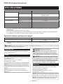
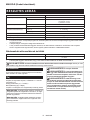
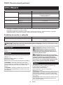
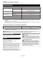
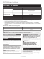
SPECIFICATIONS
Model: DDF486
Drilling capacities Steel 13 mm
Wood Auger bit: 50 mm
Self-feed bit: 76 mm
Hole saw: 152 mm
Fastening capacities Wood screw 10 mm x 90 mm
Machine screw M6
No load speed (RPM) High (2) 0 - 2,100 min-1
Low (1) 0 - 550 min-1
Overall length 178 mm
Rated voltage D.C. 18 V
Net weight 2.3 - 2.6 kg
• Due to our continuing program of research and development, the specications herein are subject to change
without notice.
• Specications may dier from country to country.
• The weight may dier depending on the attachment(s), including the battery cartridge. The lightest and heavi-
est combination, according to EPTA-Procedure 01/2014, are shown in the table.
Applicable battery cartridge and charger
Battery cartridge BL1815N / BL1820B / BL1830B / BL1840B / BL1850B / BL1860B
Charger DC18RC / DC18RD / DC18RE / DC18SD / DC18SE / DC18SF /
DC18SH
• Some of the battery cartridges and chargers listed above may not be available depending on your region of
residence.
WARNING: Only use the battery cartridges and chargers listed above. Use of any other battery cartridges
and chargers may cause injury and/or re.
Intended use
The tool is intended for drilling and screw driving in
wood, metal and plastic.
Noise
The typical A-weighted noise level determined accord-
ing to EN62841-2-1:
Sound pressure level (LpA) : 74 dB(A)
Uncertainty (K) :3dB(A)
The noise level under working may exceed 80 dB (A).
NOTE: The declared noise emission value(s) has
been measured in accordance with a standard test
method and may be used for comparing one tool with
another.
NOTE: The declared noise emission value(s)
may also be used in apreliminary assessment of
exposure.
WARNING: Wear ear protection.
WARNING:
The noise emission during actual
use of the power tool can dier from the declared
value(s) depending on the ways in which the tool is
used especially what kind of workpiece is processed.
WARNING:
Be sure to identify safety measures
to protect the operator that are based on an estima-
tion of exposure in the actual conditions of use (tak-
ing account of all parts of the operating cycle such
as the times when the tool is switched o and when
it is running idle in addition to the trigger time).
Vibration
The vibration total value (tri-axial vector sum) deter-
mined according to EN62841-2-1:
Work mode: drilling into metal
Vibration emission (ah,D) : 2.5 m/s2 or less
Uncertainty (K) :1.5 m/s2
NOTE: The declared vibration total value(s) has been
measured in accordance with a standard test method
and may be used for comparing one tool with another.
NOTE: The declared vibration total value(s) may also
be used in apreliminary assessment of exposure.

5ENGLISH
WARNING:
The vibration emission during actual
use of the power tool can dier from the declared val-
ue(s) depending on the ways in which the tool is used
especially what kind of workpiece is processed.
WARNING:
Be sure to identify safety measures
to protect the operator that are based on an estima-
tion of exposure in the actual conditions of use (tak-
ing account of all parts of the operating cycle such
as the times when the tool is switched o and when
it is running idle in addition to the trigger time).
EC Declaration of Conformity
For European countries only
The EC declaration of conformity is included as Annex A
to this instruction manual.
SAFETY WARNINGS
General power tool safety warnings
WARNING:
Read all safety warnings, instruc-
tions, illustrations and specications provided with this
power tool. Failure to follow all instructions listed below
may result in electric shock, re and/or serious injury.
Save all warnings and instruc-
tions for future reference.
The term "power tool" in the warnings refers to your
mains-operated (corded) power tool or battery-operated
(cordless) power tool.
Cordless driver drill safety warnings
Safety instructions for all operations
1. Use the auxiliary handle(s). Loss of control can
cause personal injury.
2.
Hold the power tool by insulated gripping surfaces,
when performing an operation where the cutting
accessory or fasteners may contact hidden wiring.
Cutting accessory or fasteners contacting a"live" wire
may make exposed metal parts of the power tool "live"
and could give the operator an electric shock.
3.
Always be sure you have a rm footing. Be sure no
one is below when using the tool in high locations.
4. Hold the tool rmly.
5. Keep hands away from rotating parts.
6. Do not leave the tool running. Operate the tool
only when hand-held.
7. Do not touch the drill bit or the workpiece
immediately after operation; they may be
extremely hot and could burn your skin.
8.
Some material contains chemicals which may be
toxic. Take caution to prevent dust inhalation and
skin contact. Follow material supplier safety data.
9. If the drill bit cannot be loosened even you
open the jaws, use pliers to pull it out. In such a
case, pulling out the drill bit by hand may result in
injury by its sharp edge.
10. Make sure there are no electrical cables, water
pipes, gas pipes etc. that could cause a hazard
if damaged by use of the tool.
Safety instructions when using long drill bits
1.
Never operate at higher speed than the maximum
speed rating of the drill bit. At higher speeds, the
bit is likely to bend if allowed to rotate freely without
contacting the workpiece, resulting in personal injury.
2. Always start drilling at low speed and with the
bit tip in contact with the workpiece. At higher
speeds, the bit is likely to bend if allowed to rotate
freely without contacting the workpiece, resulting
in personal injury.
3. Apply pressure only in direct line with the bit
and do not apply excessive pressure. Bits can
bend causing breakage or loss of control, resulting
in personal injury.
SAVE THESE INSTRUCTIONS.
WARNING: DO NOT let comfort or familiarity
with product (gained from repeated use) replace
strict adherence to safety rules for the subject
product. MISUSE or failure to follow the safety
rules stated in this instruction manual may cause
serious personal injury.
Important safety instructions for
battery cartridge
1.
Before using battery cartridge, read all instruc-
tions and cautionary markings on (1) battery char-
ger, (2) battery, and (3) product using battery.
2. Do not disassemble or tamper with the battery
cartridge. It may result in are, excessive heat,
or explosion.
3. If operating time has become excessively
shorter, stop operating immediately. It may
result in a risk of overheating, possible burns
and even an explosion.
4.
If electrolyte gets into your eyes, rinse them out
with clear water and seek medical attention right
away. It may result in loss of your eyesight.
5. Do not short the battery cartridge:
(1) Do not touch the terminals with any con-
ductive material.
(2) Avoid storing battery cartridge in a con-
tainer with other metal objects such as
nails, coins, etc.
(3) Do not expose battery cartridge to water
or rain.
A battery short can cause a large current ow,
overheating, possible burns and even a breakdown.
6. Do not store and use the tool and battery car-
tridge in locations where the temperature may
reach or exceed 50 °C (122 °F).
7. Do not incinerate the battery cartridge even if
it is severely damaged or is completely worn
out. The battery cartridge can explode in a re.
8. Do not nail, cut, crush, throw, drop the battery
cartridge, or hit against a hard object to the
battery cartridge. Such conduct may result in a
re, excessive heat, or explosion.
9. Do not use a damaged battery.

6ENGLISH
10. The contained lithium-ion batteries are subject
to the Dangerous Goods Legislation require-
ments.
For commercial transports e.g. by third parties,
forwarding agents, special requirement on pack-
aging and labeling must be observed.
For preparation of the item being shipped, consult-
ing an expert for hazardous material is required.
Please also observe possibly more detailed
national regulations.
Tape or mask o open contacts and pack up the
battery in such amanner that it cannot move
around in the packaging.
11. When disposing the battery cartridge, remove
it from the tool and dispose of it in a safe
place. Follow your local regulations relating to
disposal of battery.
12. Use the batteries only with the products
specied by Makita. Installing the batteries to
non-compliant products may result in are, exces-
sive heat, explosion, or leak of electrolyte.
13. If the tool is not used for a long period of time,
the battery must be removed from the tool.
14. During and after use, the battery cartridge may
take on heat which can cause burns or low
temperature burns. Pay attention to the han-
dling of hot battery cartridges.
15. Do not touch the terminal of the tool imme-
diately after use as it may get hot enough to
cause burns.
16. Do not allow chips, dust, or soil stuck into the
terminals, holes, and grooves of the battery
cartridge. It may result in poor performance or
breakdown of the tool or battery cartridge.
17. Unless the tool supports the use near
high-voltage electrical power lines, do not use
the battery cartridge near high-voltage electri-
cal power lines. It may result in amalfunction or
breakdown of the tool or battery cartridge.
18. Keep the battery away from children.
SAVE THESE INSTRUCTIONS.
CAUTION: Only use genuine Makita batteries.
Use of non-genuine Makita batteries, or batteries that
have been altered, may result in the battery bursting
causing res, personal injury and damage. It will
also void the Makita warranty for the Makita tool and
charger.
Tips for maintaining maximum
battery life
1. Charge the battery cartridge before completely
discharged. Always stop tool operation and
charge the battery cartridge when you notice
less tool power.
2.
Never recharge a fully charged battery cartridge.
Overcharging shortens the battery service life.
3.
Charge the battery cartridge with room tempera-
ture at 10 °C - 40 °C (50 °F - 104 °F). Let a hot
battery cartridge cool down before charging it.
4. When not using the battery cartridge, remove
it from the tool or the charger.
5. Charge the battery cartridge if you do not use
it for a long period (more than six months).
FUNCTIONAL DESCRIPTION
CAUTION: Always be sure that the tool is
switched o and the battery cartridge is removed
before adjusting or checking function on the tool.
Installing or removing battery cartridge
CAUTION: Always switch o the tool before
installing or removing of the battery cartridge.
CAUTION: Hold the tool and the battery car-
tridge rmly when installing or removing battery
cartridge. Failure to hold the tool and the battery
cartridge rmly may cause them to slip o your hands
and result in damage to the tool and battery cartridge
and apersonal injury.
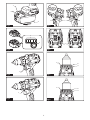
►Fig.1: 1. Red indicator 2. Button 3. Battery cartridge
To remove the battery cartridge, slide it from the tool
while sliding the button on the front of the cartridge.
To install the battery cartridge, align the tongue on the
battery cartridge with the groove in the housing and slip
it into place. Insert it all the way until it locks in place
with alittle click. If you can see the red indicator on the
upper side of the button, it is not locked completely.
CAUTION: Always install the battery cartridge
fully until the red indicator cannot be seen. If not,
it may accidentally fall out of the tool, causing injury to
you or someone around you.
CAUTION: Do not install the battery cartridge
forcibly. If the cartridge does not slide in easily, it is
not being inserted correctly.
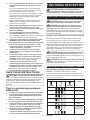
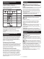
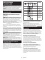
Indicating the remaining battery capacity
Only for battery cartridges with the indicator
►Fig.2: 1. Indicator lamps 2. Check button
Press the check button on the battery cartridge to indi-
cate the remaining battery capacity. The indicator lamps
light up for a few seconds.
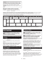
Indicator lamps Remaining
capacity
Lighted O Blinking
75% to 100%
50% to 75%
25% to 50%
0% to 25%
Charge the
battery.
The battery
may have
malfunctioned.

7ENGLISH
NOTE: Depending on the conditions of use and the
ambient temperature, the indication may dier slightly
from the actual capacity.
NOTE: The rst (far left) indicator lamp will blink when
the battery protection system works.
Tool / battery protection system
The tool is equipped with atool/battery protection sys-
tem. This system automatically cuts o the power to
extend tool and battery life. The tool will automatically
stop during operation if the tool or battery is placed
under one of the following conditions:
Overload protection
This protection works when the tool/battery is operated in a
manner that causes it to draw an abnormally high current. In this
situation, turn the tool o and stop the application that caused
the tool to become overloaded. Then turn the tool on to restart.
Overheat protection
This protection works when the tool or battery is over-
heated. In this situation, let the tool and battery cool
before turning the tool on again.
Overdischarge protection
This protection works when the remaining battery
capacity gets low. In this situation, remove the battery
from the tool and charge the battery.
Switch action
CAUTION: Before installing the battery car-
tridge into the tool, always check to see that the
switch trigger actuates properly and returns to
the "OFF" position when released.
►Fig.3: 1. Switch trigger
To start the tool, simply pull the switch trigger. Tool
speed is increased by increasing pressure on the switch
trigger. Release the switch trigger to stop.
NOTE: The tool automatically stops if you keep pull-
ing the switch trigger for about 6 minutes.
Lighting up the front lamp
CAUTION: Do not look in the light or see the
source of light directly.
►Fig.4: 1. Lamp
Pull the switch trigger to light up the lamp. The lamp
keeps on lighting while the switch trigger is being pulled.
The lamp goes out approximately 10 seconds after
releasing the switch trigger.
NOTE: When the tool is overheated, the tool stops
automatically and the lamp starts ashing. In this
case, release the switch trigger. The lamp turns o in
one minute.
NOTE: Use adry cloth to wipe the dirt o the lens of
the lamp. Be careful not to scratch the lens of lamp, or
it may lower the illumination.
Reversing switch action
CAUTION: Always check the direction of
rotation before operation.
CAUTION:
Use the reversing switch only after
the tool comes to a complete stop. Changing the direc-
tion of rotation before the tool stops may damage the tool.
CAUTION:
When not operating the tool, always
set the reversing switch lever to the neutral position.
►Fig.5: 1. Reversing switch lever
This tool has a reversing switch to change the direction of rota-
tion. Depress the reversing switch lever from the A side for clock-
wise rotation or from the B side for counterclockwise rotation.
When the reversing switch lever is in the neutral posi-
tion, the switch trigger cannot be pulled.
Speed change
CAUTION:
Always set the speed change lever
fully to the correct position. If you operate the tool with
the speed change lever positioned halfway between the
"1" side and "2" side, the tool may be damaged.
CAUTION: Do not use the speed change lever
while the tool is running. The tool may be damaged.
►Fig.6: 1. Speed change lever
Displayed
Number Speed Torque Applicable
operation
1Low High Heavy load-
ing operation
2High Low Light loading
operation
To change the speed, switch o the tool rst. Push the
speed change lever to display "2" for high speed or "1"
for low speed. Be sure that the speed change lever is
set to the correct position before operation.
If the tool speed is coming down extremely during the
operation with display "2", push the lever to display "1"
and restart the operation.
Adjusting ring
You can select the action mode and adjust the fastening
torque with the adjusting ring.
Selecting the action mode
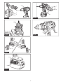
►Fig.7: 1. Adjusting ring 2. Mark 3.Arrow
This tool has two action modes.
Drilling mode (rotation only)
1 - 21 Screwdriving mode (rotation
with clutch)
Select the mode suitable for your work. Turn the adjusting ring and
align the mark that you select with the arrow on the tool body.
NOTICE:
Always set the ring correctly to your desired
mode mark. If you operate the tool with the ring positioned
halfway between the mode marks, the tool may be damaged.
NOTICE: Do not change the action mode while tool
is rotating.

8ENGLISH
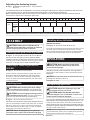
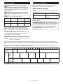
Adjusting the fastening torque
►Fig.8: 1. Adjusting ring 2. Mark (1 - 21 graduation)
3. Arrow
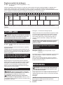
The fastening torque can be adjusted in 21 levels by turning the adjusting ring. Align the graduations with the arrow
on the tool body. You can get the minimum fastening torque at 1and maximum torque at 21.
Before actual operation, drive atrial screw into your material or apiece of duplicate material to determine which
torque level is required for a particular application.
Graduation 12345678910 11 12 13 14 15 16 17 18 19 20 21
Machine screw M4 M5 M6 –
Wood
screw
Soft wood
(e.g. pine)
–ø3.5 x 22 ø4.1 x 38 –ø5.1 x 50 –
Hard
wood
(e.g.
lauan)
–ø3.5 x 22 ø4.1 x 38 –ø5.1 x 50 –
NOTE: The adjusting ring does not lock when the arrow is positioned only halfway between the graduations.
ASSEMBLY
CAUTION: Always be sure that the tool is
switched o and the battery cartridge is removed
before carrying out any work on the tool.
Installing side grip (auxiliary handle)
►Fig.9: 1. Side grip 2. Protrusion 3. Groove 4. Arm
Always use the side grip to ensure operating safety.
Install the side grip so that the protrusions on the arm t
in the grooves on the tool barrel. Turn the grip clockwise
to secure it. The grip can be xed at desired angle.
Installing or removing driver bit/
drill bit
►Fig.10: 1. Sleeve 2. Close 3. Open
Turn the sleeve counterclockwise to open the chuck
jaws. Place the driver bit/drill bit in the chuck as far
as it will go. Turn the sleeve clockwise to tighten the
chuck. To remove the driver bit/drill bit, turn the sleeve
counterclockwise.
Installing hook
CAUTION:
When installing the hook, always
secure it with the screw rmly. If not, the hook may
come o from the tool and result in the personal injury.
CAUTION:
Use the hanging/mounting parts for
their intended purposes only. Using for unintended
purpose may cause accident or personal injury.
►Fig.11: 1. Groove 2. Hook 3. Screw
The hook is convenient for temporarily hanging the tool.
This can be installed on either side of the tool. To install
the hook, insert it into a groove in the tool housing on
either side and then secure it with a screw. To remove,
loosen the screw and then take it out.
NOTICE: When hanging the tool on your belt
using the hook, remove the bit and the side grip.
Installing driver bit holder
Optional accessory
►Fig.12: 1. Driver bit holder 2. Driver bit
Fit the driver bit holder into the protrusion at the tool foot
on either right or left side and secure it with a screw.
When not using the driver bit, keep it in the driver bit hold-
ers. Driver bits 45 mm-long (1-3/4") can be kept there.
OPERATION
CAUTION: When the speed comes down
extremely, reduce the load or stop the tool to
avoid the tool damage.
Hold the tool rmly with one hand on the grip and the
other hand on the handle to control the twisting action.
►Fig.13
NOTICE: Do not cover vents, or it may cause over-
heating and damage to the tool.
►Fig.14: 1. Vent
Screwdriving operation
CAUTION: Adjust the adjusting ring to the
proper torque level for your work.
CAUTION: Make sure that the driver bit is
inserted straight in the screw head, or the screw
and/or driver bit may be damaged.
First, turn the adjusting ring so that the arrow on the tool
body points to the proper fastening torque level (1 -21).
Place the point of the driver bit in the screw head and
apply pressure to the tool. Start the tool slowly and then
increase the speed gradually. Release the switch trigger
as soon as the clutch cuts in.
NOTE: When driving wood screw, pre-drill a pilot hole
2/3 the diameter of the screw. It makes driving easier
and prevents splitting of the workpiece.

9ENGLISH
Drilling operation
CAUTION: Pressing excessively on the tool
will not speed up the drilling. In fact, this excessive
pressure will only serve to damage the tip of your drill
bit, decrease the tool performance and shorten the
service life of the tool.
CAUTION: Hold the tool rmly and exert care
when the drill bit begins to break through the
workpiece. There is a tremendous force exerted on
the tool/drill bit at the time of hole break through.
CAUTION: A stuck drill bit can be removed
simply by setting the reversing switch to reverse
rotation in order to back out. However, the tool
may back out abruptly if you do not hold it rmly.
CAUTION: Always secure workpieces in a
vise or similar hold-down device.
CAUTION: If the tool is operated continuously
until the battery cartridge has discharged, allow
the tool to rest for 15 minutes before proceeding
with a fresh battery.
First, turn the adjusting ring so that the arrow points to
the marking. Then proceed as follows.
Drilling in wood
When drilling in wood, the best results are obtained
with wood drills equipped with a guide screw. The guide
screw makes drilling easier by pulling the drill bit into
the workpiece.
Drilling in metal
To prevent the drill bit from slipping when starting a
hole, make an indentation with a center-punch and
hammer at the point to be drilled. Place the point of the
drill bit in the indentation and start drilling.
Use a cutting lubricant when drilling metals. The excep-
tions are iron and brass which should be drilled dry.
MAINTENANCE
CAUTION: Always be sure that the tool is
switched o and the battery cartridge is removed
before attempting to perform inspection or
maintenance.
NOTICE: Never use gasoline, benzine, thinner,
alcohol or the like. Discoloration, deformation or
cracks may result.
To maintain product SAFETY and RELIABILITY,
repairs, any other maintenance or adjustment should
be performed by Makita Authorized or Factory Service
Centers, always using Makita replacement parts.
OPTIONAL
ACCESSORIES
CAUTION: These accessories or attachments
are recommended for use with your Makita tool
specied in this manual. The use of any other
accessories or attachments might present a risk of
injury to persons. Only use accessory or attachment
for its stated purpose.
If you need any assistance for more details regard-
ing these accessories, ask your local Makita Service
Center.
•Drill bits
•Driver bits
•Hook
• Grip assembly
• Makita genuine battery and charger
• Rubber pad assembly
•Wool bonnet
•Foam polishing pad
NOTE: Some items in the list may be included in the
tool package as standard accessories. They may
dier from country to country.

10 POLSKI
POLSKI (Instrukcja oryginalna)
DANE TECHNICZNE
Model: DDF486
Zakresy wiercenia Stal 13 mm
Drewno Wiertło kręte: 50 mm
Wiertło zsamoczynnym posuwem: 76 mm
Piła walcowa: 152 mm
Zakresy dokręcania Wkręt do drewna 10 mm x 90 mm
Wkręt maszynowy M6
Prędkość bez obciążenia (obr./min)
Wysoka (2) 0–2 100 min-1
Niska (1) 0–550 min-1
Długość całkowita 178 mm
Napięcie znamionowe Prąd stały 18 V
Masa netto 2,3–2,6 kg
• W związku ze stale prowadzonym przez naszą rmę programem badawczo-rozwojowym niniejsze dane mogą
ulec zmianom bez wcześniejszego powiadomienia.
• Dane techniczne mogą różnić się wzależności od kraju.
• Masa może być różna wzależności od osprzętu, wtym akumulatora. Wtabeli przedstawiona jest najlżejsza i
najcięższa konguracja, zgodnie zprocedurą EPTA 01/2014.
Kompatybilne akumulatory i ładowarki
Akumulator BL1815N / BL1820B / BL1830B / BL1840B / BL1850B / BL1860B
Ładowarka DC18RC / DC18RD / DC18RE / DC18SD / DC18SE / DC18SF /
DC18SH
• Pewne zwymienionych powyżej akumulatorów iładowarek mogą być niedostępne wregionie zamieszkania
użytkownika.
OSTRZEŻENIE: Należy używać wyłącznie akumulatorów i ładowarek wymienionych powyżej.
Używanie innych akumulatorów iładowarek może stwarzać ryzyko wystąpienia obrażeń ciała lub pożaru.
Przeznaczenie
Narzędzie jest przeznaczone do wiercenia wdrewnie,
metalu itworzywach sztucznych oraz do wkręcania
wkrętów we wspomniane materiały.
Hałas
Typowy równoważny poziom dźwięku Aokreślony w
oparciu onormę EN62841-2-1:
Poziom ciśnienia akustycznego (LpA): 74 dB(A)
Niepewność (K): 3dB(A)
Poziom hałasu podczas pracy może przekraczać 80 dB (A).
WSKAZÓWKA: Deklarowana wartość emisji hałasu
została zmierzona zgodnie ze standardową metodą
testową imożna ją wykorzystać do porównywania
narzędzi.
WSKAZÓWKA: Deklarowaną wartość emisji hałasu
można także wykorzystać we wstępnej ocenie
narażenia.
OSTRZEŻENIE: Nosić ochronniki słuchu.
OSTRZEŻENIE: Poziom hałasu wytwa-
rzanego podczas rzeczywistego użytkowania
elektronarzędzia może się różnić od wartości
deklarowanej w zależności od sposobu użytko-
wania narzędzia, a w szczególności od rodzaju
obrabianego elementu.
OSTRZEŻENIE: W oparciu o szacowane
narażenie w rzeczywistych warunkach użytkowa-
nia należy określić środki bezpieczeństwa w celu
zapewnienia ochrony operatora (uwzględniając
wszystkie elementy cyklu działania, tj. czas, kiedy
narzędzie jest wyłączone i kiedy pracuje na biegu
jałowym, a także czas, kiedy jest włączone).

11 POLSKI
Drgania
Całkowita wartość poziomu drgań (suma wektorów w 3
osiach) określona zgodnie znormą EN62841-2-1:
Tryb pracy: wiercenie wmetalu
Emisja drgań (ah,D): 2,5 m/s2lub mniej
Niepewność (K): 1,5 m/s2
WSKAZÓWKA: Deklarowana wartość poziomu
drgań została zmierzona zgodnie ze standardową
metodą testową imożna ją wykorzystać do porówny-
wania narzędzi.
WSKAZÓWKA: Deklarowaną wartość poziomu
drgań można także wykorzystać we wstępnej ocenie
narażenia.
OSTRZEŻENIE:
Drgania wytwarzane podczas
rzeczywistego użytkowania elektronarzędzia mogą
się różnić od wartości deklarowanej w zależności
od sposobu użytkowania narzędzia, a w szczegól-
ności od rodzaju obrabianego elementu.
OSTRZEŻENIE: W oparciu o szacowane
narażenie w rzeczywistych warunkach użytkowa-
nia należy określić środki bezpieczeństwa w celu
zapewnienia ochrony operatora (uwzględniając
wszystkie elementy cyklu działania, tj. czas, kiedy
narzędzie jest wyłączone i kiedy pracuje na biegu
jałowym, a także czas, kiedy jest włączone).
Deklaracja zgodności WE
Dotyczy tylko krajów europejskich
Deklaracja zgodności WE jest dołączona jako załącznik
Ado niniejszej instrukcji obsługi.
OSTRZEŻENIA
DOTYCZĄCE
BEZPIECZEŃSTWA
Ogólne zasady bezpiecznej
eksploatacji elektronarzędzi
OSTRZEŻENIE: Należy zapoznać się z
ostrzeżeniami dotyczącymi bezpieczeństwa,
instrukcjami, ilustracjami i danymi technicz-
nymi dołączonymi do tego elektronarzędzia.
Niezastosowanie się do podanych poniżej instrukcji
może prowadzić do porażenia prądem, pożaru i/lub
poważnych obrażeń ciała.
Wszystkie ostrzeżenia i instruk-
cje należy zachować do wykorzy-
stania w przyszłości.
Pojęcie „elektronarzędzie", występujące wwymienio-
nych tu ostrzeżeniach, odnosi się do elektronarzędzia
zasilanego zsieci elektrycznej (z przewodem zasilają-
cym) lub do elektronarzędzia akumulatorowego (bez
przewodu zasilającego).
Ostrzeżenia dotyczące
bezpieczeństwa dla akumulatorowej
wiertarko-wkrętarki
Instrukcje bezpieczeństwa dotyczące wszystkich
wykonywanych prac
1.
Używać uchwytu pomocniczego lub uchwytów pomocni-
czych. Utrata kontroli może spowodować obrażenia ciała.
2.
Podczas wykonywania prac, przy których
osprzęt tnący lub elementy złączne mogą
zetknąć się z niewidoczną instalacją elek-
tryczną, trzymać elektronarzędzie za izolowane
powierzchnie rękojeści. Zetknięcie osprzętu
tnącego lub elementów złącznych zprzewodem
elektrycznym znajdującym się pod napięciem może
sprawić, że odsłonięte elementy metalowe elektro-
narzędzia również znajdą się pod napięciem, gro-
żąc porażeniem operatora prądem elektrycznym.
3.
Podczas pracy należy zadbać o dobre oparcie dla
nóg. W przypadku pracy na pewnej wysokości upew-
nić się, że na dole nie przebywają żadne osoby.
4. Narzędzie należy trzymać mocno i pewnie.
5. Trzymać ręce z dala od części obrotowych.
6.
Nie pozostawiać włączonego narzędzia. Narzędzie
można uruchomić tylko, gdy jest trzymane w rękach.
7.
Nie dotykać wiertła ani części obrabianej od razu
po zakończeniu danej operacji; mogą one być
bardzo gorące i spowodować oparzenie skóry.
8. Niektóre materiały zawierają substancje
chemiczne, które mogą być toksyczne.
Unikać wdychania pyłu i kontaktu ze skórą.
Przestrzegać przepisów bezpieczeństwa poda-
nych przez dostawcę materiałów.
9.
Jeśli wiertło nie chce się poluzować po otwarciu
szczęk, należy wyjąć je kombinerkami. Wyciąganie
wiertła ręką wtakim przypadku może spowodować
skaleczenie zpowodu ostrych krawędzi.
10.
Należy się upewnić, że w obszarze pracy nie ma
żadnych przewodów elektrycznych, rur instalacji
wodnej, rur z gazem itp., które mogłyby stanowić
zagrożenie po uszkodzeniu przez narzędzie.
Instrukcje bezpieczeństwa dotyczące używania
długich wierteł
1. Nigdy nie należy ustawiać prędkości wyższej
niż maksymalna prędkość określona dla
danego wiertła. Przy wyższych prędkościach
wiertło obracające się swobodnie bez kontaktu z
obrabianym elementem może ulec wygięciu, co
może prowadzić do obrażeń ciała.
2.
Wiercenie należy zawsze rozpoczynać od niskiej
prędkości oraz z końcówką wiertła stykającą się
z obrabianym elementem. Przy wyższych prędko-
ściach wiertło obracające się swobodnie bez kon-
taktu zobrabianym elementem może ulec wygięciu,
co może prowadzić do obrażeń ciała.
3. Należy stosować nacisk wyłącznie bezpośred-
nio w jednej linii z wiertłem i unikać wywierania
nadmiernego nacisku. Wiertło może się wygiąć,
powodując uszkodzenie lub utratę kontroli, co
może prowadzić do obrażeń ciała.
ZACHOWAĆ NINIEJSZĄ
INSTRUKCJĘ.

12 POLSKI
OSTRZEŻENIE: NIE WOLNO pozwolić,
aby wygoda lub rutyna (nabyta w wyniku wielo-
krotnego używania urządzenia) zastąpiły ścisłe
przestrzeganie zasad bezpieczeństwa obsługi.
NIEWŁAŚCIWE UŻYTKOWANIE narzędzia lub
niestosowanie się do zasad bezpieczeństwa
podanych w niniejszej instrukcji obsługi może
prowadzić do poważnych obrażeń ciała.
Ważne zasady bezpieczeństwa
dotyczące akumulatora
1.
Przed użyciem akumulatora zapoznać się ze
wszystkimi instrukcjami i znakami ostrzegaw-
czymi na (1) ładowarce, (2) akumulatorze i (3)
produkcie, w którym będzie używany akumulator.
2. Nie rozmontowywać ani modykować akumu-
latora. Może to spowodować pożar, przegrzanie
lub wybuch.
3. Jeśli czas działania uległ znacznemu skróce-
niu, należy natychmiast przerwać pracę. Może
bowiem dojść do przegrzania, ewentualnych
poparzeń, a nawet eksplozji.
4. W przypadku przedostania się elektrolitu do
oczu, przemyć je czystą wodą i niezwłocznie
uzyskać pomoc lekarską. Może on bowiem
spowodować utratę wzroku.
5. Nie doprowadzać do zwarcia akumulatora:
(1) Nie dotykać styków materiałami przewo-
dzącymi prąd.
(2) Unikać przechowywania akumulatora w
pojemniku z metalowymi przedmiotami,
takimi jak gwoździe, monety itp.
(3)
Chronić akumulator przed deszczem lub wodą.
Zwarcie prowadzi do przepływu prądu elek-
trycznego o dużym natężeniu i przegrzania
akumulatora, co w konsekwencji może grozić
poparzeniami a nawet awarią urządzenia.
6. Narzędzia i akumulatora nie wolno przechowy-
wać ani używać w miejscach, w których tempe-
ratura osiąga bądź przekracza 50°C (122°F).
7. Akumulatorów nie wolno spalać, również tych
poważnie uszkodzonych lub całkowicie zuży-
tych. Akumulator może eksplodować w ogniu.
8. Nie należy przecinać ani zgniatać akumulatora,
wbijać w niego gwoździ, rzucać nim, upusz-
czać, ani uderzać akumulatorem o twarde
obiekty. Takie działanie może spowodować pożar,
przegrzanie lub wybuch.
9. Nie wolno używać uszkodzonego akumulatora.
10. Stanowiące wyposażenie akumulatory lito-
wo-jonowe podlegają przepisom dotyczącym
produktów niebezpiecznych.
Na potrzeby transportu komercyjnego, np. świad-
czonego przez rmy trzecie czy spedycyjne,
należy przestrzegać specjalnych wymagań w
zakresie pakowania ioznaczania etykietami.
Przygotowanie produktu do wysyłki wymaga skon-
sultowania się ze specjalistą ds. materiałów niebez-
piecznych. Należy także przestrzegać przepisów
krajowych, które mogą być bardziej szczegółowe.
Zakleić taśmą lub zaślepić otwarte styki akumula-
tora oraz zabezpieczyć go, aby nie mógł się prze-
suwać wopakowaniu.
11.
Jeśli zajdzie konieczność utylizacji akumulatora,
należy wyjąć go z narzędzia i przekazać w bez-
pieczne miejsce. Postępować zgodnie z przepisami
lokalnymi dotyczącymi utylizacji akumulatorów.
12. Używać akumulatorów tylko z produktami
określonymi przez rmę Makita. Zastosowanie
akumulatorów wniezgodnych produktach może
spowodować pożar, przegrzanie, wybuch lub
wyciek elektrolitu.
13. Jeśli narzędzie nie będzie używane przez dłuż-
szy czas, należy wyjąć z niego akumulator.
14. Przed użyciem akumulatora i po jego użyciu
akumulator może pozostawać nagrzany, co
może spowodować poparzenia lub poparzenia
w niskiej temperaturze. Z gorącym akumulato-
rem należy obchodzić się ostrożnie.
15. Nie należy dotykać styku narzędzia bezpośred-
nio po jego użyciu, ponieważ może on być na
tyle gorący, że spowoduje oparzenia.
16. Nie należy dopuszczać, aby wióry, kurz lub
błoto gromadziły się na stykach, w otworach
i rowkach akumulatora. Może to spowodować
obniżenie wydajności lub uszkodzenie narzędzia
lub akumulatora.
17. Jeśli narzędzie nie jest przeznaczone do
użytku w pobliżu linii wysokiego napięcia,
nie należy korzystać z akumulatora w ich
sąsiedztwie. Może to spowodować nieprawidło-
wości wdziałaniu lub uszkodzenie narzędzia lub
akumulatora.
18. Przechowywać akumulator w miejscu niedo-
stępnym dla dzieci.
ZACHOWAĆ NINIEJSZE
INSTRUKCJE.
PRZESTROGA: Używać wyłącznie oryginal-
nych akumulatorów rmy Makita. Używanie nie-
oryginalnych akumulatorów rm innych niż Makita lub
akumulatorów, które zostały zmodykowane, może
spowodować wybuch akumulatora ipożar, obrażenia
ciała oraz zniszczenie mienia. Stanowi to również
naruszenie warunków gwarancji rmy Makita doty-
czących narzędzia iładowarki.
Wskazówki dotyczące zacho-
wania maksymalnej trwałości
akumulatora
1. Akumulator należy naładować zanim zostanie
do końca rozładowany. Po zauważeniu spadek
mocy narzędzia należy przerwać pracę i nała-
dować akumulator.
2. Nie wolno ładować powtórnie w pełni nałado-
wanego akumulatora. Przeładowanie akumula-
tora skraca jego trwałość.
3.
Akumulator należy ładować w temperaturze poko-
jowej w przedziale 10–40°C (50–104°F). W przy-
padku gorącego akumulatora przed przystąpie-
niem do ładowania należy poczekać, aż ostygnie.
4. Jeśli akumulator nie jest używany, należy go
wyjąć z narzędzia lub ładowarki.
5. Akumulatory niklowo-wodorkowe należy nała-
dować po okresie długiego nieużytkowania
(dłuższego niż sześć miesięcy).

13 POLSKI
OPIS DZIAŁANIA
PRZESTROGA: Przed przystąpieniem do regu-
lacji lub przeglądu narzędzia upewnić się, że jest
ono wyłączone, a akumulator został wyjęty.
Wkładanie i wyjmowanie akumulatora
PRZESTROGA: Przed włożeniem lub wyjęciem
akumulatora należy zawsze wyłączyć narzędzie.
PRZESTROGA: Podczas wkładania lub wyjmo-
wania akumulatora należy mocno trzymać narzę-
dzie i akumulator. Wprzeciwnym razie mogą się one
wyślizgnąć zrąk, powodując uszkodzenie narzędzia
lub akumulatora iobrażenia ciała.
►Rys.1:
1. Czerwony wskaźnik 2. Przycisk 3. Akumulator
Aby wyjąć akumulator, przesuń przycisk znajdujący się
wprzedniej jego części iwysuń akumulator.
Aby włożyć akumulator, wyrównaj występ na akumulato-
rze zrowkiem wobudowie iwsuń go na swoje miejsce.
Akumulator należy wsunąć do oporu, aż się zatrzaśnie na
miejscu, co jest sygnalizowane delikatnym kliknięciem.
Jeśli wgórnej części przycisku jest widoczny czerwony
wskaźnik, akumulator nie został całkowicie zatrzaśnięty.
PRZESTROGA:
Akumulator należy włożyć do
końca, tak aby czerwony wskaźnik nie był widoczny. W
przeciwnym razie może przypadkowo wypaść znarzędzia,
powodując obrażenia operatora lub osób postronnych.
PRZESTROGA: Nie wkładać akumulatora na
siłę. Jeśli akumulator nie daje się swobodnie wsunąć,
oznacza to, że został włożony nieprawidłowo.
Wskazanie stanu naładowania akumulatora
Tylko w przypadku akumulatorów ze wskaźnikiem
►Rys.2: 1. Lampki wskaźnika 2. Przycisk kontrolny
Nacisnąć przycisk kontrolny na akumulatorze wcelu
wyświetlenia stanu naładowania akumulatora. Lampki
wskaźnika zaświecą się przez kilka sekund.
Lampki wskaźnika Pozostała
energia
akumulatora
Świeci się Wyłączony Miga
75–100%
50–75%
25–50%
0–25%
Naładować
akumulator.
Akumulator
może nie
działać
poprawnie.
WSKAZÓWKA: Zależnie od warunków użytkowania
itemperatury otoczenia, wskazywany poziom może
nieznacznie się różnić od rzeczywistego stanu nała-
dowania akumulatora.
WSKAZÓWKA: Pierwsza (skrajnie po lewej stronie)
lampka wskaźnika miga, gdy układ zabezpieczenia
akumulatora jest aktywny.
Układ zabezpieczenia narzędzia/
akumulatora
Narzędzie jest wyposażone wukład zabezpieczenia
narzędzia/akumulatora. Układ ten automatycznie
odcina zasilanie wcelu wydłużenia trwałości narzę-
dzia iakumulatora. Narzędzie zostanie automatycznie
zatrzymane podczas pracy wnastępujących sytuacjach
związanych znarzędziem lub akumulatorem:
Zabezpieczenie przed przeciążeniem
To zabezpieczenie jest aktywowane, gdy narzędzie/
akumulator obsługiwane(-y) jest wsposób powodujący
nadmiernie wysoki pobór prądu. Wtakiej sytuacji należy
wyłączyć narzędzie izaprzestać wykonywania czynno-
ści powodującej jego przeciążenie. Następnie należy
włączyć narzędzie wcelu ponownego uruchomienia.
Zabezpieczenie przed przegrzaniem
To zabezpieczenie jest aktywowane wprzypadku prze-
grzania narzędzia lub akumulatora. Wtakiej sytuacji
należy odczekać, aż narzędzie iakumulator ostygną
przed ponownym włączeniem narzędzia.
Zabezpieczenie przed nadmiernym
rozładowaniem
To zabezpieczenie jest aktywowane, gdy stan nałado-
wania akumulatora jest niski. Wtakiej sytuacji należy
wyjąć akumulator znarzędzia inaładować go.
Działanie przełącznika
PRZESTROGA: Przed włożeniem akumulatora
do narzędzia należy zawsze sprawdzić, czy spust
przełącznika działa prawidłowo i czy powraca do
położenia wyłączenia po jego zwolnieniu.
►Rys.3: 1. Spust przełącznika
Wcelu uruchomienia narzędzia wystarczy pociągnąć
spust przełącznika. Prędkość narzędzia zwiększa się
wraz ze zwiększaniem nacisku na spust przełącznika.
Wcelu zatrzymania urządzenia należy zwolnić spust
przełącznika.
WSKAZÓWKA: Narzędzie zatrzyma się automa-
tycznie, gdy spust przełącznika pozostanie wciśnięty
przez około 6min.

14 POLSKI
Włączanie lampki czołowej
PRZESTROGA: Nie patrzeć na światło ani
bezpośrednio na źródło światła.
►Rys.4: 1. Lampka
Wcelu włączenia lampki należy pociągnąć za spust
przełącznika. Lampka świeci, dopóki spust przełącznika
jest naciskany. Lampka wyłącza się po około 10 sod
zwolnienia spustu przełącznika.
WSKAZÓWKA: Wprzypadku przegrzania narzędzie
automatycznie się wyłączy izacznie migać lampka.
Wtakiej sytuacji należy zwolnić spust przełącznika.
Lampka wyłączy się po upływie jednej minuty.
WSKAZÓWKA:Aby usunąć zabrudzenia zklosza
lampki, należy użyć suchej szmatki. Uważać, aby nie
zarysować klosza lampki, gdyż może to zmniejszyć
natężenie oświetlenia.
Działanie przełącznika zmiany
kierunku obrotów
PRZESTROGA: Przed przystąpieniem do pracy
należy zawsze sprawdzić ustawiony kierunek
obrotów.
PRZESTROGA: Przełącznika zmiany kie-
runku obrotów można użyć tylko po całkowitym
zatrzymaniu narzędzia. Zmiana kierunku obro-
tów przed zatrzymaniem się narzędzia grozi jego
uszkodzeniem.
PRZESTROGA: Gdy narzędzie nie jest uży-
wane, należy zawsze ustawić dźwignię prze-
łącznika zmiany kierunku obrotów w położeniu
neutralnym.
►Rys.5: 1. Dźwignia przełącznika zmiany kierunku
obrotów
Omawiane narzędzie jest wyposażone wprzełącznik
umożliwiający zmianę kierunku obrotów. Wcelu uzy-
skania obrotów wprawą stronę należy wcisnąć dźwi-
gnię przełącznika zmiany kierunku obrotów po stronie
A, natomiast aby uzyskać obroty wlewą stronę, należy
wcisnąć dźwignię przełącznika po stronie B.
Gdy dźwignia przełącznika zmiany kierunku obrotów
znajduje się wpołożeniu neutralnym, spust przełącz-
nika jest zablokowany.
Zmiana prędkości
PRZESTROGA: Dźwignię zmiany prędkości
należy zawsze ustawiać dokładnie w wybranej
pozycji. Wprzypadku uruchomienia narzędzia przy
dźwigni zmiany prędkości ustawionej wpołowie
między pozycją „1” i„2” może dojść do uszkodzenia
narzędzia.
PRZESTROGA: Nie wolno używać dźwi-
gni zmiany prędkości, gdy narzędzie pracuje.
Narzędzie może ulec uszkodzeniu.
►Rys.6: 1. Dźwignia zmiany prędkości
Widoczna
cyfra Prędkość Moment
obrotowy Odpowiedni
tryb pracy
1Niska Wysoka Praca przy
dużym
obciążeniu
2Wysoki Niski Praca przy
małym
obciążeniu
Wcelu zmiany prędkości należy najpierw wyłączyć
narzędzie. Przesunąć dźwignię zmiany prędkości tak,
aby była widoczna cyfra „2”, jeśli ma zostać wybrana
wysoka prędkość, lub aby była widoczna cyfra „1”, jeśli
ma zostać wybrana niska prędkość. Przed rozpoczę-
ciem pracy należy sprawdzić, czy dźwignia zmiany
prędkości jest ustawiona we właściwym położeniu.
Jeśli prędkość narzędzia drastycznie spadnie podczas
pracy zdźwignią ustawioną wpołożeniu „2”, należy
przesunąć dźwignię tak, aby pojawiła się cyfra „1” i
ponownie przystąpić do pracy.
Pierścień regulacyjny
Przy użyciu pierścienia regulacyjnego można wybrać
tryb pracy iustawić moment dokręcenia.
Wybór trybu pracy
►Rys.7: 1. Pierścień regulacyjny 2. Symbol
3. Strzałka
Narzędzie ma dwa tryby pracy.
–tryb wiercenia (tylko ruch
obrotowy)
1–21 –tryb wkręcania (ruch obro-
towy ze sprzęgłem)
Wybrać tryb odpowiedni do danej pracy. Obrócić pier-
ścień regulacyjny iwyrównać wybrany symbol trybu ze
strzałką znajdującą się na korpusie narzędzia.
UWAGA: Pierścień należy zawsze ustawić dokładnie
wpozycji symbolu odpowiadającego wybranemu
trybowi pracy. Wprzypadku uruchomienia narzędzia,
gdy pierścień jest ustawiony między symbolami trybu
pracy, może dojść do uszkodzenia narzędzia.
UWAGA: Nie zmieniać trybu pracy wczasie obrotów
narzędzia.

15 POLSKI
Regulacja momentu dokręcenia
►Rys.8: 1. Pierścień regulacyjny 2. Symbol (1–21 na
podziałce) 3. Strzałka
Moment dokręcenia można regulować w21 poziomach, obracając pierścień regulacyjny. Wyrównać podziałkę ze
strzałką znajdującą się na korpusie narzędzia. Położenie 1odnosi się do minimalnego momentu dokręcenia, asym-
bol 21 do maksymalnego momentu dokręcenia.
Przed przystąpieniem do pracy należy przeprowadzić próbę wkręcania wdany element lub inny element ztego
samego materiału, aby ustalić poziom momentu dokręcenia wymagany wdanym zastosowaniu.
Podziałka 12345678910 11 12 13 14 15 16 17 18 19 20 21
Wkręt maszynowy M4 M5 M6 –
Wkręt
do
drewna
Miękkie
drewno
(np.
sosna)
–ø3,5 x 22 ø4,1 x 38 –ø5,1 x 50 –
Twarde
drewno
(np.
mahoń)
–ø3,5 x 22 ø4,1 x 38 –ø5,1 x 50 –
WSKAZÓWKA: Pierścień regulacyjny nie zablokuje się, jeśli strzałka jest ustawiona wpołowie odcinka pomiędzy
podziałkami.
MONTAŻ
PRZESTROGA: Przed przystąpieniem do prac
konserwacyjnych przy narzędziu upewnić się,
że jest ono wyłączone, a akumulator został wyjęty.
Instalowanie uchwytu bocznego
(rękojeść pomocnicza)
►Rys.9: 1. Uchwyt boczny 2. Występ 3. Bruzda
4. Ramię
Wcelu zapewnienia bezpieczeństwa obsługi należy
zawsze korzystać zuchwytu bocznego.
Założyć uchwyt boczny wtaki sposób, aby występy
znajdujące się na ramieniu weszły wrowki wtulei
narzędzia. Przekręcić uchwyt wprawo, aby go zamoco-
wać. Uchwyt można zamocować pod żądanym kątem.
Wkładanie i wyjmowanie końcówki
wkrętakowej/wiertła
►Rys.10: 1. Tuleja 2. Zamykanie 3. Otwieranie
Aby otworzyć szczęki uchwytu, obrócić tuleję wlewą
stronę. Umieścić jak najgłębiej końcówkę wkrętakową/
wiertło wuchwycie. Obrócić tuleję wprawą stronę, aby
zacisnąć uchwyt. Wcelu wyjęcia końcówki wkrętako-
wej/wiertła obrócić tuleję wlewą stronę.
Zamontowanie zaczepu
PRZESTROGA: Podczas instalacji zaczepu
należy go zawsze mocno zamocować śrubą. Jeśli
to wymaganie nie zostanie spełnione, zaczep może
się odłączyć od narzędzia ispowodować obrażenia
ciała.
PRZESTROGA: Części do wieszania/części
mocujących należy używać tylko zgodnie z ich
przeznaczeniem. Użycie niezgodne zprzeznacze-
niem może doprowadzić do wypadku lub uszkodzeń
ciała.
►Rys.11: 1. Rowek 2. Zaczep 3. Wkręt
Zaczep służy do wygodnego, tymczasowego zawie-
szania narzędzia. Można go zamontować zjednej lub
zdrugiej strony narzędzia. Aby zamontować zaczep,
należy wsunąć go wrowek wobudowie narzędzia
znajdujący się zobu stron, anastępnie przykręcić go
wkrętem. Aby wymontować zaczep, należy odkręcić
wkręt iwyjąć zaczep.
UWAGA: W przypadku zawieszania narzędzia na
pasku przy użyciu zaczepu należy zdemontować
końcówkę i uchwyt boczny.
Zamontowywanie uchwytu
końcówki wkrętakowe
Akcesoria opcjonalne
►Rys.12: 1. Uchwyt na końcówki wkrętakowe
2. Końcówka wkrętakowa
Włożyć uchwyt na końcówki wkrętakowe do występu w
stopie narzędzia zprawej bądź zlewej strony iprzymo-
cować go wkrętem.
Nieużywane końcówki wkrętakowe należy przechowy-
wać wuchwytach. Wuchwytach można przechowywać
końcówki odługości 45 mm (1-3/4″).

16 POLSKI
OBSŁUGA
PRZESTROGA:
W przypadku drastycznego spadku
prędkości należy zredukować obciążenie lub wyłączyć
narzędzie, aby nie dopuścić do jego uszkodzenia.
Narzędzie należy wsposób pewny trzymać jedną ręką za
rączkę, adrugą za uchwyt, aby kontrolować jego przekręcanie.
►Rys.13
UWAGA: Nie zasłaniać otworów wentylacyjnych. W
przeciwnym razie może to doprowadzić do przegrza-
nia iuszkodzenia narzędzia.
►Rys.14: 1. Otwór wentylacyjny
Wkręcanie
PRZESTROGA: Ustawić pierścień regulacyjny
w pozycji odpowiadającej właściwemu dla danej
operacji momentowi dokręcenia.
PRZESTROGA:
Końcówka wkrętakowa powinna być
wprowadzona do łba wkrętu w linii prostej z wkrętem, w prze-
ciwnym razie wkręt i/lub końcówka mogą ulec uszkodzeniu.
Najpierw obrócić pierścień regulacyjny tak, aby strzałka
na korpusie narzędzia wskazywała odpowiedni moment
dokręcenia (1–21).
Wsunąć czubek końcówki wkrętakowej do gniazda we
łbie wkrętu idocisnąć narzędzie. Uruchomić narzędzie
powoli, anastępnie stopniowo zwiększać prędkość.
Zwolnić spust przełącznika, gdy tylko zadziała sprzęgło.
WSKAZÓWKA: Wprzypadku wkręcania wkrętu do
drewna należy wstępnie nawiercić otwór prowadzący
ośrednicy 2/3 średnicy wkrętu. Ułatwi to wkręcanie i
zapobiegnie rozłupywaniu się elementu obrabianego.
Wiercenie
PRZESTROGA:
Wywieranie nadmiernego nacisku
na narzędzie nie przyspiesza wiercenia. Wpraktyce,
wywieranie nadmiernego nacisku przyczynia się jedynie
do uszkodzenia końcówki wiertła, zmniejszenia wydajno-
ści iskrócenia okresu eksploatacyjnego narzędzia.
PRZESTROGA:
Gdy wiertło zaczyna przebijać na
wylot otwór w obrabianym elemencie, należy zachować
ostrożność i mocno trzymać narzędzie. W momencie przebi-
jania otworu na narzędzie/wiertło wywierana jest olbrzymia siła.
PRZESTROGA:
Zakleszczone wiertło można łatwo
wyjąć, zmieniając kierunek obrotów i wyciągając
wiertło. Należy jednak pamiętać, że narzędzie może się
gwałtownie cofnąć, jeśli nie będzie mocno trzymane.
PRZESTROGA:
Elementy obrabiane należy
zawsze mocować w imadle lub podobnym uchwycie.
PRZESTROGA:
Jeżeli narzędzie jest używane
bez przerwy aż do rozładowania akumulatora, należy
je odstawić na 15 minut przed podjęciem pracy na
nowo z użyciem innego naładowanego akumulatora.
Najpierw obrócić pierścień regulacyjny tak, aby strzałka
wskazywała symbol .Następnie postępować zgod-
nie zponiższym opisem.
Wiercenie w drewnie
Wprzypadku wiercenia wdrewnie najlepsze rezultaty
uzyskuje się, stosując wiertła zakończone wkrętem
prowadzącym. Wkręt prowadzący ułatwia wiercenie,
ponieważ wciąga wiertło welement obrabiany.
Wiercenie w metalu
Aby uniknąć ześlizgiwania się wiertła na początku operacji,
należy za pomocą punktaka imłotka wykonać wgłębienie
wmiejscu, wktórym ma być wykonany otwór. Umieścić
końcówkę wiertła we wgłębieniu irozpocząć wiercenie.
Podczas wiercenia wmetalu należy stosować odpo-
wiednie chłodziwo. Wyjątki stanowią żelazo imosiądz,
które należy wiercić na sucho.
KONSERWACJA
PRZESTROGA: Przed przystąpieniem do prze-
glądu narzędzia lub jego konserwacji upewnić się,
że jest ono wyłączone, a akumulator wyjęty.
UWAGA: Nie stosować benzyny, rozpuszczalni-
ków, alkoholu itp. środków. Mogą one powodo-
wać odbarwienia, odkształcenia lub pęknięcia.
W celu zachowania odpowiedniego poziomu
BEZPIECZEŃSTWA iNIEZAWODNOŚCI produktu
wszelkie naprawy iróżnego rodzaju prace konserwacyjne
lub regulacje powinny być przeprowadzane przez autory-
zowany lub fabryczny punkt serwisowy narzędzi Makita,
zawsze zużyciem oryginalnych części zamiennych Makita.
AKCESORIA
OPCJONALNE
PRZESTROGA: Zaleca się stosowanie wymie-
nionych akcesoriów i przystawek razem z narzę-
dziem Makita opisanym w niniejszej instrukcji.
Stosowanie innych akcesoriów lub przystawek
może być przyczyną obrażeń ciała. Akcesoria lub
przystawki należy wykorzystywać tylko zgodnie zich
przeznaczeniem.
Wrazie potrzeby wszelkiej pomocy iszczegółowych
informacji na temat niniejszych akcesoriów udzielą
Państwu lokalne punkty serwisowe Makita.
• Wiertła
• Końcówki wkrętakowe
•Zaczep
• Zespół uchwytu
• Oryginalny akumulator iładowarka rmy Makita
• Zespół gumowego talerza szlierskiego
• Osłona wełniana
• Krążek zpianki do polerowania
WSKAZÓWKA: Niektóre pozycje znajdujące się na
liście mogą być dołączone do pakietu narzędziowego
jako akcesoria standardowe. Mogą to być różne
pozycje, wzależności od kraju.

17 MAGYAR
MAGYAR (Eredeti utasítások)
RÉSZLETES LEÍRÁS
Típus: DDF486
Fúrási teljesítmény Acél 13 mm
Fa Fúrófej: 50 mm
Koronafúró: 76 mm
Lyukfűrész: 152 mm
Meghúzási kapacitások Facsavar 10 mm x 90 mm
Gépcsavar M6
Üresjárati fordulatszám (f/p) Magas (2) 0 - 2 100 min-1
Alacsony (1) 0 - 550 min-1
Teljes hossz 178 mm
Névleges feszültség 18 V, egyenáram
Nettó tömeg 2,3 - 2,6 kg
• Folyamatos kutató- és fejlesztőprogramunk eredményeként az itt felsorolt tulajdonságok gyelmeztetés nélkül
megváltozhatnak.
• A tulajdonságok országról országra különbözhetnek.
• A súly afelszerelt tartozékoktól függően változhat, az akkumulátort is beleértve. Az EPTA 01/2014 eljárás
szerint meghatározott legnehezebb, illetve legkönnyebb kombináció atáblázatban látható.
Alkalmazható akkumulátorok és töltők
Akkumulátor BL1815N / BL1820B / BL1830B / BL1840B / BL1850B / BL1860B
Töltő DC18RC / DC18RD / DC18RE / DC18SD / DC18SE / DC18SF /
DC18SH
• Lakóhelyétől függően előfordulhat, hogy afent felsorolt akkumulátorok és töltők nem érhetők el.
FIGYELMEZTETÉS: Csak a fentiekben felsorolt akkumulátorokat és töltőket használja. Bármilyen más
akkumulátor vagy töltő használata sérüléseket és/vagy tüzet okozhat.
Rendeltetés
Aszerszám fúrásra és csavarbehajtásra használható,
fába, fémekbe és műanyagokba.
Zaj
Atipikus A-súlyozású zajszint, aEN62841-2-1 szerint
meghatározva:
Hangnyomásszint (LpA): 74 dB(A)
Bizonytalanság (K): 3dB(A)
Azajszint amunkavégzés során meghaladhatja a80 dB (A) értéket.
MEGJEGYZÉS: Azajkibocsátás értéke aszabványos
vizsgálati eljárásnak megfelelően lett mérve, és segít-
ségével az elektromos kéziszerszámok összehason-
líthatók egymással.
MEGJEGYZÉS: Azajkibocsátás értékének segítsé-
gével előzetesen megbecsülhető arezgésnek való
kitettség mértéke.
FIGYELMEZTETÉS: Viseljen fülvédőt!
FIGYELMEZTETÉS: A szerszám zajkibocsá-
tása egy adott alkalmazásnál eltérhet a megadott
értéktől a használat módjától, különösen a feldol-
gozott munkadarab fajtájától függően.
FIGYELMEZTETÉS: Határozza meg a kez-
elő védelmét szolgáló munkavédelmi lépéseket,
melyek az adott munkafeltételek melletti vibrációs
hatás becsült mértékén alapulnak (gyelembe
véve a munkaciklus elemeit, mint például a gép
leállításának és üresjáratának mennyiségét az
elindítások száma mellett).

18 MAGYAR
Vibráció
Avibráció teljes értéke (háromtengelyű vektorösszeg)
az EN62841-2-1 szerint meghatározva:
Üzemmód: fúrás fémbe
Rezgéskibocsátás (ah,D): 2,5 m/s2vagy kisebb
Bizonytalanság (K): 1,5 m/s2
MEGJEGYZÉS: Arezgés teljes értéke aszabványos
vizsgálati eljárásnak megfelelően lett mérve, és segít-
ségével az elektromos kéziszerszámok összehason-
líthatók egymással.
MEGJEGYZÉS: Arezgés teljes értékének segítsé-
gével előzetesen megbecsülhető arezgésnek való
kitettség mértéke.
FIGYELMEZTETÉS: A szerszám rezgéskibo-
csátása egy adott alkalmazásnál eltérhet a meg-
adott értéktől a használat módjától, különösen a
feldolgozott munkadarab fajtájától függően.
FIGYELMEZTETÉS: Határozza meg a kez-
elő védelmét szolgáló munkavédelmi lépéseket,
melyek az adott munkafeltételek melletti vibrációs
hatás becsült mértékén alapulnak (gyelembe
véve a munkaciklus elemeit, mint például a gép
leállításának és üresjáratának mennyiségét az
elindítások száma mellett).
EK Megfelelőségi nyilatkozat
Csak európai országokra vonatkozóan
Az EK-megfelelőségi nyilatkozat az útmutató „A” mel-
lékletében található.
BIZTONSÁGI
FIGYELMEZTETÉS
A szerszámgépekre vonatkozó
általános biztonsági
gyelmeztetések
FIGYELMEZTETÉS: Olvassa el a szerszám-
géphez mellékelt összes biztonsági gyelmezte-
tést, utasítást, illusztrációt és a műszaki adatokat.
Akövetkezőkben leírt utasítások gyelmen kívül
hagyása elektromos áramütést, tüzet és/vagy súlyos
sérülést eredményezhet.
Őrizzen meg minden gyelmez-
tetést és utasítást a későbbi tájé-
kozódás érdekében.
Agyelmeztetésekben szereplő "szerszámgép" kife-
jezés az Ön hálózatról (vezetékes) vagy akkumulá-
torról (vezeték nélküli) működtetett szerszámgépére
vonatkozik.
Biztonsági gyelmeztetések
akkumulátoros
fúró-csavarbehajtóhoz
Biztonsági utasítások minden művelethez
1. Használja a kiegészítő fogantyú(ka)t. Az irányí-
tás elvesztése személyi sérülést okozhat.
2.
Az elektromos szerszámot kizárólag a szigetelt
markolási felületeinél fogva tartsa, amikor olyan
műveletet végez, melynek során a vágóelem
vagy a kötőelem rejtett vezetékekbe ütközhet.
Ha avágóelem vagy akötőelem áram alatt lévő
vezetékekkel érintkezik, aszerszám fém alkatrészei
is áram alá kerülhetnek, és megrázhatják akezelőt.
3.
Mindig stabil helyzetben dolgozzon. A szerszám
magasban történő használatkor győződjön meg
arról, hogy nem tartózkodik-e valaki odalent.
4. Biztosan tartsa a szerszámot.
5. Ne nyúljon a forgó részekhez.
6.
Ne hagyja a működő szerszámot felügyelet nél-
kül. Csak kézben tartva használja a szerszámot.
7. Ne érintse meg a fúróhegyet vagy a munkada-
rabot közvetlenül a művelet befejezése után;
rendkívül forrók lehetnek és megégethetik.
8. Egyes anyagok mérgező vegyületet tartal-
mazhatnak. Gondoskodjon a por belélegzése
elleni és érintés elleni védelemről. Tartsa be az
anyag szállítójának biztonsági utasításait.
9. Ha a fúróhegyet akkor se lehet kilazítani, ha
szétnyitja a pofákat, akkor fogóval húzza ki.
Ebben az esetben afúróhegy kézzel történő kihú-
zása sérülést okozhat az éles szélek miatt.
10. Ellenőrizze, hogy vannak-e sérülés esetén
veszélyt jelentő elektromos kábelek, vízcsö-
vek, gázcsövek stb. a munkaterületen.
Biztonsági utasítások hosszú fúróhegyek
használatához
1. Soha ne működtesse nagyobb sebességen,
mint a fúróhegy maximális sebességi besoro-
lása. Nagyobb sebességeknél afúróhegy elhajol-
hat, ha engedik szabadon, amunkadarab érintése
nélkül forogni, és ez személyi sérülést okozhat.
2. Mindig kis sebességen kezdjen fúrni, és úgy,
hogy a fúró hegye érintkezzen a munkadarab-
bal. Nagyobb sebességeknél afúróhegy elhajol-
hat, ha engedik szabadon, amunkadarab érintése
nélkül forogni, és ez személyi sérülést okozhat.
3. Csak a fúróhegy egyenes vonalában alkalmaz-
zon nyomást, és ne alkalmazzon túlzott nyo-
mást.Afúróhegyek elhajolhatnak, ezért eltörhet-
nek vagy elveszítheti az irányítást, és ez személyi
sérülést okozhat.
ŐRIZZE MEG EZEKET AZ
UTASÍTÁSOKAT.
FIGYELMEZTETÉS: NE HAGYJA, hogy (a
termék többszöri használatából eredő) kényelem
és megszokás váltsa fel a termék biztonsági
előírásainak szigorú betartását. A HELYTELEN
HASZNÁLAT és a használati útmutatóban sze-
replő biztonsági előírások megszegése súlyos
személyi sérülésekhez vezethet.

19 MAGYAR
Fontos biztonsági utasítások az
akkumulátorra vonatkozóan
1. Az akkumulátor használata előtt tanulmá-
nyozza át az akkumulátortöltőn (1), az akkumu-
látoron (2) és az akkumulátorral működtetett
terméken (3) olvasható összes utasítást és
gyelmeztető jelzést.
2. Ne szerelje szét, és ne módosítsa az akkumulá-
tort. Tüzet, túlzott hőt vagy robbanást okozhat.
3. Ha a működési idő nagyon lerövidült, azonnal
hagyja abba a használatot. Ez a túlmelegedés,
esetleges égések és akár robbanás veszélyé-
vel is járhat.
4. Ha elektrolit kerül a szemébe, mossa ki azt
tiszta vízzel és azonnal kérjen orvosi segítsé-
get. Ez a látásának elvesztését okozhatja.
5. Ne zárja rövidre az akkumulátort:
(1) Ne érjen az érintkezőkhöz elektromosan
vezető anyagokkal.
(2) Ne tárolja az akkumulátort más fémtár-
gyakkal, mint pl. szegekkel, érmékkel,
stb. egy helyen.
(3) Ne tegye ki az akkumulátort víznek vagy
esőnek.
Az akkumulátor rövidzárlata nagy áramerőssé-
get, túlmelegedést, égéseket, sőt akár meghi-
básodást is okozhat.
6. Ne tárolja és használja a szerszámot vagy az
akkumulátort olyan helyen, ahol a hőmérséklet
elérheti vagy meghaladhatja az 50 °C-t (122 °F).
7. Ne égesse el az akkumulátort még akkor
sem, ha az komolyan megsérült vagy teljesen
elhasználódott. Az akkumulátor a tűzben
felrobbanhat.
8. Ne szúrja meg, ne vágja meg, ne törje össze,
ne dobja el és ne ejtse le az akkumulátort,
illetve ne üsse hozzá kemény tárgyhoz. Az
ilyen magatartás tüzet, túlzott hőt vagy robbanást
okozhat.
9. Ne használjon sérült akkumulátort.
10. A készülékben található lítium-ion akkumuláto-
rokra a veszélyes árukkal kapcsolatos előírá-
sok vonatkoznak.
Atermék pl. harmadik felek, fuvarozó cégek stb.
által történő szállítása esetén minden esetben
tartsa szem előtt acsomagoláson és acímkén
található speciális követelményeket.
Atermék szállításra történő felkészítése esetén
vegye fel akapcsolatot egy veszélyes anyagokkal
foglalkozó szakemberrel. Kérjük, hogy az eset-
legesen szigorúbb nemzeti előírásokat is vegye
gyelembe.
Ragassza le akiálló érintkezőket, illetve oly
módon csomagolja be az akkumulátort, hogy az
ne tudjon elmozdulni acsomagolásban.
11. Az akkumulátor ártalmatlanításakor vegye ki
azt a szerszámból, és ártalmatlanítsa egy biz-
tonságos helyen. Az akkumulátor ártalmatlaní-
tásakor tartsa be a helyi előírásokat.
12. Az akkumulátorokat csak a Makita által meg-
jelölt termékekhez használja. Ha az akkumu-
látorokat azokkal nem kompatibilis termékekbe
helyezi, az tűzhöz, túlmelegedéshez, robbanás-
hoz vagy elektrolitszivárgáshoz vezethet.
13. Ha a szerszám hosszabb ideig nincs hasz-
nálatban, az akkumulátort ki kell venni a
szerszámból.
14. Használat közben és után az akkumulátor
felforrósodhat, ami égési sérülést vagy ala-
csony hőmérsékletű égési sérülést okozhat.
Figyeljen oda a forró akkumulátor kezelésére.
15. Ne érintse meg közvetlenül a szerszám érintke-
zőjét, mert elég forró lehet ahhoz, hogy égési
sérüléseket okozzon.
16. Ne engedje, hogy forgács, por vagy sár tapad-
jon az akkumulátor érintkezőire, lyukaiba és
hornyaiba. Az aszerszám vagy az akkumulátor
gyenge teljesítményét vagy meghibásodását
okozhatja.
17. Hacsak a szerszám nem támogatja a nagyfe-
szültségű elektromos vezetékek közelében tör-
ténő használatot, ne használja az akkumulátort
nagyfeszültségű elektromos vezetékek köze-
lében. Az aszerszám vagy az akkumulátor hibás
működését vagy meghibásodását okozhatja.
18. Tartsa távol a gyermekektől az akkumulátort.
ŐRIZZE MEG EZEKET AZ
UTASÍTÁSOKAT.
VIGYÁZAT: Csak eredeti Makita akkumuláto-
rokat használjon. A nem eredeti Makita akkumu-
látorok vagy módosított akkumulátorok használata
esetén az akkumulátor felrobbanhat, ami tüzet,
személyi sérülést és anyagi kárt okozhat. AMakita
szerszámra és töltőre vonatkozó Makita garanciát is
érvénytelenítheti.
Tippek az akkumulátor maximá-
lis élettartamának eléréséhez
1. Töltse fel az akkumulátort, mielőtt teljesen
lemerülne. Állítsa le a gépet, és töltse fel az
akkumulátort, ha a gép erejének csökkenését
észleli.
2. Soha ne töltse újra a teljesen feltöltött akku-
mulátort. A túltöltés csökkenti az akkumulátor
élettartamát.
3. Töltse az akkumulátort szobahőmérsékleten,
10 °C - 40 °C (50 °F - 104 °F) között. Töltés előtt
hagyja lehűlni a fölforrósodott akkumulátort.
4. Ha nem használja az akkumulátort, vegye ki a
szerszámból vagy a töltőből.
5. Töltse fel az akkumulátort, ha hosszabb ideje
(több mint hat hónapja) nem használta azt.

20 MAGYAR
A MŰKÖDÉS LEÍRÁSA
VIGYÁZAT: Minden esetben ellenőrizze, hogy
a szerszám ki van kapcsolva és az akkumulátor
eltávolításra került mielőtt beállít vagy ellenőriz
valamilyen funkciót a szerszámon.
Az akkumulátor behelyezése és eltávolítása
VIGYÁZAT: Mindig kapcsolja ki az eszközt,
mielőtt behelyezi vagy eltávolítja az akkumulátort.
VIGYÁZAT:
Az akkumulátor behelyezésekor vagy eltá-
volításakor erősen fogja meg a szerszámot és az akkumulá-
tort. Ha nem fogja erősen aszerszámot és az akkumulátort, azok
kicsúszhatnak akezei közül, ami aszerszám és az akkumulátor
károsodásához, de akár személyi sérüléshez is vezethet.
►Ábra1: 1. Piros jel 2. Gomb 3.Akkumulátor
Az akkumulátoregység kivételéhez nyomja be az akkumu-
látoregység elején található gombot, és húzza le agépről.
Az akkumulátor beszereléséhez illessze az akkumulátor
nyelvét aburkolaton található vájatba és csúsztassa a
helyére. Egészen addig tolja be, amíg az akkumulátor egy
kis kattanással ahelyére nem ugrik. Ha látható apiros jel a
gomb felső oldalán, akkor agomb nem kattant be teljesen.
VIGYÁZAT:
Mindig tolja be teljesen az akkumulá-
tort, amíg a piros jel el nem tűnik. Ha ez nem történik
meg, akkor az akkumulátor kieshet aszerszámból, és
Önnek vagy akörnyezetében másnak sérülést okozhat.
VIGYÁZAT: Ne erőltesse az akkumulátort behe-
lyezéskor. Ha az akkumulátor nem csúszik be köny-
nyedén, akkor nem megfelelően lett behelyezve.
Az akkumulátor töltöttségének jelzése
Csak állapotjelzős akkumulátorok esetén
►Ábra2: 1. Jelzőlámpák 2. Check (ellenőrzés) gomb
Nyomja meg az ellenőrzőgombot, hogy az akkumulátortöltött-
ség-jelző megmutassa ahátralévő akkumulátor-kapacitást. Ekkor
atöltöttségiszint-jelző lámpák néhány másodpercre kigyulladnak.
Jelzőlámpák Töltöttségi
szint
Világító lámpa
KI
Villogó lámpa
75%-tól
100%-ig
50%-tól
75%-ig
25%-tól
50%-ig
0%-tól 25%-ig
Töltse fel az
akkumulátort.
Lehetséges,
hogy az
akkumulátor
meghibáso-
dott.
MEGJEGYZÉS: Az adott munkafeltételektől és akör-
nyezet hőmérsékletétől függően ajelzett töltöttségi
szint némileg eltérhet atényleges töltöttségi szinttől.
MEGJEGYZÉS: Az első (bal oldali szélső) jelzőlámpa
villog, ha az akkumulátorvédő rendszer működik.
Szerszám-/akkumulátorvédő rendszer
Agép szerszám-/akkumulátorvédő rendszerrel van felszerelve.
Arendszer automatikusan kikapcsolja az áramellátást, így
megnöveli aszerszám és az akkumulátor élettartamát. Agép
használat közben automatikusan leáll, ha aszerszám vagy az
akkumulátor akövetkező állapotok valamelyikébe kerül:
Túlterhelésvédelem
Ez avédelem akkor működik, ha aszerszámot/akkumulátort úgy
működteti, hogy áramfelvétele rendellenesen magas. Ilyenkor kap-
csolja ki aszerszámot, és fejezze be azt aműveletet, amelyik atúlter-
helést okozza. Amunka újrakezdéséhez kapcsolja be aszerszámot.
Túlmelegedés elleni védelem
Ez avédelem akkor működik, ha aszerszám vagy az akku-
mulátor túlhevül. Ilyenkor hagyja lehűlni aszerszámot és az
akkumulátort, mielőtt ismét bekapcsolná aszerszámot.
Mélykisütés elleni védelem
Ez avédelem akkor működik, ha amaradék akkumulá-
torkapacitás alacsony. Ilyenkor vegye ki az akkumulá-
tort aszerszámból, majd töltse fel azt.
A kapcsoló használata
VIGYÁZAT: Mielőtt behelyezi az akkumulátort a
szerszámba, mindig ellenőrizze, hogy a kapcsoló-
gomb hibátlanul működik és felengedéskor „OFF”
állásba áll-e.
►Ábra3: 1. Kapcsológomb
Aszerszám bekapcsolásához egyszerűen húzza meg akapcso-
lógombot. Ha erősebben nyomja akapcsolót, aszerszám fordu-
latszáma növekszik. Amegállításához engedje el akapcsolót.
MEGJEGYZÉS: A szerszám automatikusan megáll,
ha akapcsológombot 6percen keresztül folyamato-
san húzza.
Az elülső lámpa bekapcsolása
VIGYÁZAT: Ne tekintsen a fénybe vagy ne
nézze egyenesen a fényforrást.
►Ábra4: 1. Lámpa
Húzza meg akapcsológombot alámpa bekapcsolásához. Alámpa
addig világít, amíg akapcsológomb meg van húzva. Alámpa a
kapcsológomb elengedése után 10 másodperccel alszik ki.
MEGJEGYZÉS:
Ha a szerszám túlmelegszik, akkor auto-
matikusan leáll, és alámpa villogni kezd. Ilyen esetben engedje
fel akapcsológombot. Alámpa egy perc múlva kialszik.
MEGJEGYZÉS: Száraz ruhadarabbal törölje le a
szennyeződést alámpa lencséjéről. Ügyeljen arra
hogy ne karcolja meg alámpa lencséjét, ez csökkent-
heti amegvilágítás erősségét.
Pagina se încarcă...
Pagina se încarcă...
Pagina se încarcă...
Pagina se încarcă...
Pagina se încarcă...
Pagina se încarcă...
Pagina se încarcă...
Pagina se încarcă...
Pagina se încarcă...
Pagina se încarcă...
Pagina se încarcă...
Pagina se încarcă...
Pagina se încarcă...
Pagina se încarcă...
Pagina se încarcă...
Pagina se încarcă...
Pagina se încarcă...
Pagina se încarcă...
Pagina se încarcă...
Pagina se încarcă...
Pagina se încarcă...
Pagina se încarcă...
Pagina se încarcă...
Pagina se încarcă...
Pagina se încarcă...
Pagina se încarcă...
Pagina se încarcă...
Pagina se încarcă...
Pagina se încarcă...
Pagina se încarcă...
Pagina se încarcă...
Pagina se încarcă...
Pagina se încarcă...
Pagina se încarcă...
Pagina se încarcă...
Pagina se încarcă...
Pagina se încarcă...
Pagina se încarcă...
Pagina se încarcă...
Pagina se încarcă...
-
 1
1
-
 2
2
-
 3
3
-
 4
4
-
 5
5
-
 6
6
-
 7
7
-
 8
8
-
 9
9
-
 10
10
-
 11
11
-
 12
12
-
 13
13
-
 14
14
-
 15
15
-
 16
16
-
 17
17
-
 18
18
-
 19
19
-
 20
20
-
 21
21
-
 22
22
-
 23
23
-
 24
24
-
 25
25
-
 26
26
-
 27
27
-
 28
28
-
 29
29
-
 30
30
-
 31
31
-
 32
32
-
 33
33
-
 34
34
-
 35
35
-
 36
36
-
 37
37
-
 38
38
-
 39
39
-
 40
40
-
 41
41
-
 42
42
-
 43
43
-
 44
44
-
 45
45
-
 46
46
-
 47
47
-
 48
48
-
 49
49
-
 50
50
-
 51
51
-
 52
52
-
 53
53
-
 54
54
-
 55
55
-
 56
56
-
 57
57
-
 58
58
-
 59
59
-
 60
60


Makita DDF486 Manual de utilizare
- Categorie
- Burghie combinate fără fir
- Tip
- Manual de utilizare
în alte limbi
- slovenčina: Makita DDF486 Používateľská príručka
- polski: Makita DDF486 Instrukcja obsługi
Lucrări înrudite
-
Makita DDF489 Manual de utilizare
-
-
-
-
Makita DHP485 Manual de utilizare
-
Makita HP488D Manual de utilizare
-
Makita DHP483 Cordless Hammer Driver Drill Manual de utilizare
-
Makita DDF485 Manual de utilizare
-
-