
en
de
fr
it
nl
es
pt
sv
da
no
fi
el
pl
hu
cs
tr
ro
sl
sk
bg
sr
hr
uk
ru
Handling instructions
Bedienungsanleitung
Mode d’emploi
Istruzioni per l’uso
Gebruiksaanwijzing
Instrucciones de manejo
Instruções de uso
Bruksanvisning
Brugsanvisning
Bruksanvisning
Käyttöohjeet
Οδηγίες χειρισμού
Instrukcja obsługi
Kezelési utasítás
Návod k obsluze
Kullanım talimatları
Instrucţiuni de utilizare
Navodila za rokovanje
Pokyny na manipuláciu
Инструкция за експлоатация
Uputstvo za rukovanje
Upute za rukovanje
Iнструкції щодо поводження з
пристроєм
Инструкция по эксплуатации
en
de
fr
it
nl
es
pt
sv
da
no
fi
el
pl
hu
cs
tr
ro
sl
sk
bg
sr
hr
uk
ru
CG 25EUP2 (L) / CG 25EUP2
CG25EUP2 (L)

2
1
J
Q
S
R
X
V
T
P
U
I
K
M
H
B
G
F
N
E
D
CG25EUP2
C
M
W
L
A
O
N
F
G
E
D
B
M
I
K
CG25EUP2 (L)
23
1
2
3
4
5
6
7
1/3
2/3
H

3
456
9
8
10
11
789
12
10 11 14
14
17
13
16
19
18
15
20
21
22
12 13

4
15 16 17
23
24
25
18 19
25
26
27
28
29
30
20
21 22 23
31
32
33
24 25 26
34
RUN
START

5
27 28 29
30 31 32
T
31
33 34 35
35
36
36
0.6 mm
37 38
37

6
39 40 41
39
40
38
10 cm
10 cm
10 cm
39
42 43
42
41
11-14 cm
11-14 cm
44
43

English
7
(Original instructions)
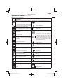
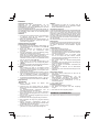
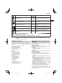
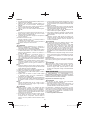
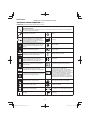
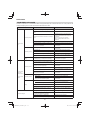
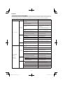
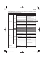
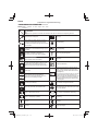
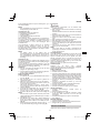
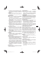
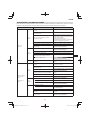
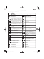
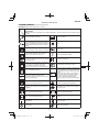
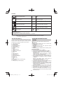
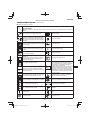
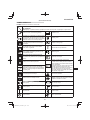
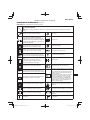
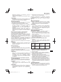
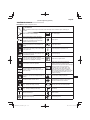
MEANINGS OF SYMBOLS
NOTE: Some units do not carry them.
Symbols
WARNING
The following show symbols used for the machine. Be sure that you understand their meaning before use.
Grass Trimmer / Brush Cutter Engine oil fi ll
It is important that you read, fully understand
and observe the following safety precautions
and warnings. Careless or improper use of the
unit may cause serious or fatal injury.
Idle speed adjustment
Read, understand and follow all warnings and
instructions in this manual and on the unit.
Priming pump
Always wear eye, head and ear protectors when
using this unit.
Guaranteed sound power level
Do not use metal/rigid blades when this sign is
shown on the unit.
Blade thrust may occur when the spinning
blade contacts a solid object in the critical area.
A dangerous reaction may occur causing the
entire unit and operator to be thrust violently.
This reaction is called blade thrust. As a result,
the operator may lose control of the unit which
may cause serious or fatal injury. Blade thrust is
more likely to occur in areas where it is diffi cult
to see the material to be cut.
Keep all children, bystandards and helpers
15 m away from the unit. If anyone approaches
you, stop the engine and cutting attachment
immediately.
Be careful of thrown objects.
Hot Surface – Contact with hot surface can
cause serious burns.
min
-1
Shows maximum shaft speed. Do not use the
cutting attachment whose max rpm is below the
shaft rpm.
The hedge trimmer attachment cannot be used
on models with this label.
Gloves should be worn when necessary, e.g.,
when assembling cutting equipment.
Indicate handle location. Arrows which show
limits for handle positioning.
Use anti-slip and sturdy footwear. Displacement
Choke – Run position (Open) Spark plug
Choke – Start position (Closed)
Idle
Idling speed
On/Start Speed of output shaft
Off /Stop
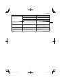
P
Max. engine output
Emergency stop Fuel tank capacity
Fuel fi ll Engine oil capacity

English
8
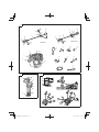
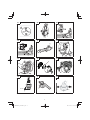
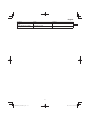
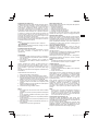
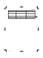
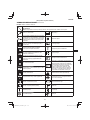
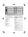
WHAT IS WHAT? (Fig. 1)
Since this manual covers several models, there may be
some diff erence between pictures and your unit. Use the
instructions that apply to your unit.
A: Fuel cap
B: Throttle trigger
C: Starter handle
D: Cutting attachment guard
E: Cutting attachment
F: Drive shaft tube
G: Handle
H: Hanger
I: Ignition switch
J: Harness
K: Throttle trigger lockout
L: Choke lever
M: Engine
N: Gear case
O: Oil cap
P: Combi box spanner
Q: Handling instructions
R: Swivel cap
S: Goggles
T: Hex bar wrench
U: Spanner
V: Blade cover (if so equipped)
W: Engine cover
X: Cord clump (if so equipped)
WARNINGS AND SAFETY
INSTRUCTIONS
Pay special attention to statements preceded by the
following words:
WARNING
Indicates a strong possibility of severe personal injury or
loss of life, if instructions are not followed.
CAUTION
Indicates a possibility of personal injury or equipment
damage, if instructions are not followed.
NOTE
Helpful information for correct function and use.
Operator safety
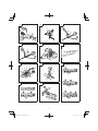
○ Wear head protection (1). (Fig. 2)
○ Always wear a safety face shield or goggles (2). (Fig. 2)
○ Wear approved hearing protection (3). (Fig. 2)
Long-term exposure to noise can result in permanent
hearing impairment.
Pay attention to your surroundings. Be aware of any
bystanders who may be signaling a problem.
Remove safety equipment immediately upon shutting off
engine.
○ Always wear heavy, long-sleeved shirts (4) and long
pants (5) and non-slip boots (6) and gloves (7). (Fig. 2)
Do not wear loose clothing, jewelry, short pants, sandals
or go barefoot.
Secure hair so it is above shoulder length.
○ Do not operate this tool when you are tired, ill or under
the infl uence of alcohol, drugs or medication.
○ Do not operate the tool at night or under bad weather
conditions when visibility is poor. And do not operate the
tool when it is raining or right after it has been raining.
Working on slippery ground could lead to an accident if
you lose your balance.
○ Never let a child or inexperienced person operate the
machine.
○ Do not start the engine if there are any fl ammables such
as dry leaves, waste paper or fuel in the vicinity.
○ Never start or run the engine inside a closed room or
building. Breathing exhaust fumes can kill.
○ Keep handles free of oil and fuel.
○ Keep hands away from cutting equipment.
○ Do not grab or hold the unit by the cutting equipment.
○ Gloves should be worn when installing or removing the
cutting attachment. Failure to do so may result in injury.
○ When the unit is shut off , make sure the cutting
attachment has stopped before the unit is set down.
○ When operation is prolonged, take a break periodically
so that you may avoid possible Hand-Arm Vibration
Syndrome (HAVS) which is caused by vibration.
WARNING
○ Always operate the tool with proper protective equipment
and clothing. Failure to do so may result in accidents
such as burns or injuries. (Fig. 2)
○ Do not touch the spark plug area or high voltage during
operation. Doing so may result in electric shock.
○ Do not allow children near the tool during operation.
○ Do not touch the engine, muffl er cover or exhaust vent
during or shortly after operation. Doing so may result in
burn or injury.
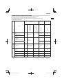
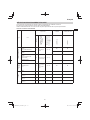
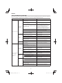
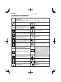
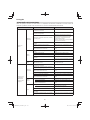
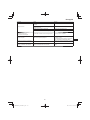
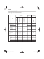
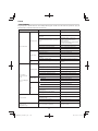
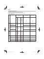
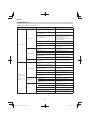
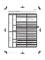
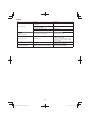
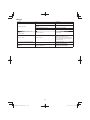
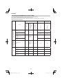
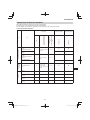
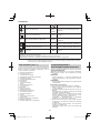
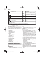
Dry weight
L
WA, Ra(G)
2000/14/EC
Guaranteed sound power level LwA by
2000/14/EC
Racing
Cutting attachment
a
hv, eq(F)
Vibration level by ISO 22867
Front or Left handle / Equivalent*
L
pA, eq
ISO22868
Sound pressure level LpA by ISO 22868
Equivalent*
a
hv, eq(R)
Vibration level by ISO 22867
Rear or Right handle / Equivalent*
L
WA, Ra(M)
2000/14/EC
Measured sound power level LwA by 2000/14/
EC
Racing
K
Uncertainty
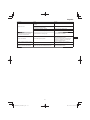
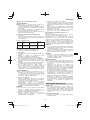
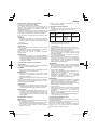
Before using your machine
• Read the manual carefully.
• Check that the cutting equipment is correctly assembled and adjusted.
• Start the unit and check the carburetor adjustment. See “MAINTENANCE”.
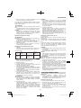
NOTE: Equivalent noise level / vibration level are calculated as the time-weighted energy total for noise / vibration levels
under various working conditions with the following time distribution:
* 1/2 Idle, 1/2 racing.

English
9
○ Antivibration systems do not guarantee that you will
not sustain Hand-Arm Vibration Syndrome or carpal
tunnel syndrome. Therefore, continual and regular users
should monitor closely the condition of their hands and
fi ngers. If any of the above symptoms appear, seek
medical advice immediately.
○ If you are using any medical electric/electronic devices
such as a pacemaker, consult your physician as well as
the device manufacturer prior to operating any power
equipment.
Unit/machine safety
○ Inspect the entire unit/machine before each use.
Replace damaged parts. Check for fuel leaks and make
sure all fasteners are in place and securely tightened.
○ Replace parts that are cracked, chipped or damaged in
any way before using the unit/machine. Faulty parts may
increase the risk of accidents and may lead to an injury.
○ Make sure the cutting attachment guard and harness are
properly attached. Do not operate if cutting attachment
guard and harness is not properly attached.
○ Keep others away when making carburetor adjustments.
○ Use only accessories as recommended for this unit/
machine by the manufacturer.
○ Before operation, make sure that there are no tools such
as the adjustment key or spanner still attached to the
unit.
WARNING
○ Never modify the unit/machine in any way. Do not use
your unit/machine for any job except that for which it is
intended.
○ Non-authorized modifi cations and/or accessories may
result in serious personal injury or the death of the
operator or others.
Fuel safety
○ Pour fuel outdoors and where there are no sparks or
fl ames.
○ Use a container approved for fuel.
○ Move at least 3 m away from fueling site before starting
engine.
○ Stop engine before removing fuel cap. Do not remove
the fuel cap during operation.
○ Empty the fuel tank before storing the unit/machine. It is
recommended that the fuel be emptied after each use. If
fuel is left in the tank, store so fuel will not leak.
WARNING
○ Fuel is easy to ignite or get explosion or inhale fumes, so
that pay special attention when handling or fi lling fuel.
○ Do not smoke or allow smoking near fuel or the unit/
machine or while using the unit/machine.
○ Wipe up all fuel spills before starting engine.
○ Store unit/machine and fuel in area where fuel vapors
cannot reach sparks or open fl ames from water heaters,
electric motors or switches, furnaces. etc.
○ When using the unit in dry areas, make sure that fi re
extinguishing equipment is readily available.
○ If you shut off the engine for refueling, make sure the unit
has cooled down before adding fuel.
Cutting safety
○ Do not cut any material other than grass and brush.
○ Inspect the area to be cut before each use.
Remove objects which can be thrown or become
entangled.
Do not operate in areas where there are tree roots or
rocks.
○ For respiratory protection, wear an aerosol protection
mask when cutting the grass after insecticide is
scattered.
○ Keep others including children, animals, bystanders and
helpers outside the 15 m hazard zone. Stop the engine
immediately if you are approached.
○ Please exercise caution as engine startup may be
delayed after pulling the starter handle.
○ Always keep the engine on the right side of your body.
○ Hold the unit/machine fi rmly with both hands.
○ Keep fi rm footing and balance. Do not over-reach.
Losing your balance during work may lead to an injury.
○ Keep all parts of your body away from the muffl er and
cutting attachment when the engine is running.
○ Keep cutting attachment below knee level.
○ Please exercise caution when operating in areas where
electrical cables or gas pipes are present.
○ Do not operate the cutting attachment for anything but
clearing grass or bushes. Avoid operations where the
cutting attachment may touch water such as puddles
or dig into dirt. Failure to do so may result in injury or
damage to the unit.
○ Avoid prolonged use at low speed range in which
vibration is high. Doing so may result in engine damage.
○ When relocating to a new work area, or inspecting,
adjusting or exchanging the unit’s cutting attachments,
accessories, etc., be sure to shut off the machine and
ensure that all cutting attachments are stopped.
○ Never place the machine on the ground when running.
○ Never touch the cutting attachment when it is rotating.
○ Always ensure that the engine is shut off and any cutting
attachments have completely stopped before clearing
debris or removing grass from the cutting attachment.
○ Always carry a fi rst-aid kit when operating any power
equipment.
○ Turn off the engine and make sure the cutting attachment
has come to a full stop before removing the unit from
your body or before leaving the unit unattended.
○ If you accidentally bump or drop the unit, inspect it
immediately to make sure there are no damage, cracks
or deformations.
○ If the tool is operating poorly and produces strange noise
or vibrations, turn off the engine immediately and ask
your dealer to have it inspected and repaired.
Continued use under these conditions could lead to
injury or tool damage.
○ Use in accordance with local laws and regulations.
WARNING
KICKBACK DANGER (Fig. 3)
When using metal cutting attachments such as blades,
contact with obstacles such as trees or other hard
surfaces with the front or right portion of the spinning
attachment may force the unit to catch on an obstacle,
resulting in a kickback reaction towards the right side of
the operator.
Kickback may occur when the cutting attachment comes
into contact with tree stumps or rocks hidden behind
weeds. Always make sure there are no obstacles hidden
by weeds before starting work.
To minimize the danger of kickbacks when they do occur,
always position the unit to the right side of the body
during operation. With the operator properly positioned
as the cutting attachment rotates, this will reduce the
danger of the unit’s direct contact with the body.
Maintenance safety
○ Maintain the unit/machine according to recommended
procedures.
○ Disconnect the spark plug before performing
maintenance except for carburetor adjustments.
○ Keep others away when making carburetor adjustments.
○ Use only genuine HITACHI replacement parts as
recommended by the manufacturer.
CAUTION
Do not disassemble the recoil starter. There is a
possibility of personal injury with recoil spring.

English
10
WARNING
Improper maintenance could result in serious engine
damage or in serious personal injury.
Transport and storage
○ Carry the unit/machine by hand with the engine stopped
and the muffl er away from your body.
○ Allow the engine to cool, empty the fuel tank, and secure
the unit/machine before storing or transporting. Failure to
do so may result in fi re or accidents.
○ Empty the fuel tank before storing the unit/machine. It is
recommended that the fuel be emptied after each use. If
fuel is left in the tank, store so fuel will not leak.
○ Store unit/machine out of the reach of children.
○ Clean and maintain the unit carefully and store it in a dry
place.
○ Make sure engine switch is off when transporting or
storing.
○ When transporting and storing, either remove the cutting
attachment or place the blade cover over the blade.
○ You have to secure the machine during transport to
prevent loss of fuel, damage or injury.
○ If a warning label cannot be read, peels off or becomes
indistinct, replace it with a new one. To purchase new
labels, contact Hitachi Authorized Service Centers.
If situations occur which are not covered in this manual, take
care and use common sense. Contact Hitachi Authorized
Service Centers if you need assistance.
SPECIFICATIONS
The SPECIFICATIONS of this machine are listed in the table
on page 286.
NOTE
All data subject to change without notice.
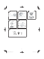
ASSEMBLY PROCEDURES
Drive shaft to engine (Fig. 4)
Loosen tube locking bolt (8) about ten turns so that the bolt
point will not obstruct drive shaft tube to be inserted. When
inserting drive shaft tube, hold the tube locking bolt outward
preventing inside fi tting from obstructing as well.
Insert the drive shaft into the clutch case of the engine
properly until the marked position (9) on the drive shaft tube
meets the clutch case.
NOTE
When it is hard to insert drive shaft up to the marked
position on the drive shaft tube, turn drive shaft by the
cutter mounting end clockwise or counter-clockwise.
Tighten tube locking bolt lining up the hole in the shaft
tube. Then tighten clamp bolt securely.
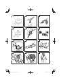
Installation of handle
(1) Loop handle type (Fig. 5)
Attach the handle to the drive shaft tube with the angle
towards the engine.
Adjust the location to the most comfortable position
before operation.
Make sure to securely attach the handle with the 2 bolts.
NOTE
If your unit has handle location label (10) on drive shaft
tube, follow the illustration.
WARNING
Do not use metal or plastic blade cutting attachments
with loop handle type.
(2) Bike handle type (Fig. 6)
Remove the handle bracket (11) from the assembly.
Place the handles and attach the handle bracket with
four bolts lightly. Adjust to appropriate position. Then
attach it fi rmly with the bolts.
Attach the protection tube to the drive shaft tube or
handle using cord clamps (12) to make sure there is no
slack. (Fig. 7)
Installation of throttle wire / stop cord
Remove air cleaner cover. (Fig. 8)
Connect stop cords. (Fig. 9)
If the throttle outer end (13) is threaded on your unit, screw it
into the cable adjuster stay (14) all the way, and then tighten
this cable end using the adjuster nut (15) against the cable
adjuster stay (14).
Connect throttle wire end (16) to swivel (17) of carburetor
and install swivel cap (18) (if so equipped) where is included
in tool bag, onto swivel (17). (Fig. 10)
Some models may come with the parts installed.
CAUTION
Open and close the throttle and verify that the swivel (17)
abuts against screw (19) when the throttle is closed.
Installation of harness
WARNING
If the product includes a harness, always make sure to
use it.
Attach the harness hook (20) to the hanger (21) on the drive
shaft tube. (Fig. 11)
Adjust the length of the harness for easy operation of the
tool.
NOTE
You may need to adjust the position of the hangar (21)
to balance the unit. To do so, loosen bolt (22) and adjust
the position of hangar (21). After adjusting as necessary,
make sure to securely tighten the bolt (22). (Fig. 11)
Installation of cutting attachment guard
WARNING
If an incorrect or faulty guard is fi tted, this may cause
serious personal injury.
CAUTION
Some cutting attachment guards are equipped with
sharp line limiters. Be careful with handling it.
NOTE
○ When using a trimmer head with two piece type cutting
attachment guard, attach the guard extension to the
cutting attachment guard. (Fig. 12)
○ The guard bracket may come already mounted to the
gear case on some models.
Align the cutting attachment guard with the guard bracket
and secure it to the drive shaft tube, using the bolt and cover
bracket. (Fig. 13)
WARNING
Remove the guard extension when using metal or plastic
blades. Failure to do so may result in injury or damage to
the cutting attachment guard.
NOTE
To remove the guard extension, refer to the drawings.
Wear gloves as the extension has a sharp line limiter,
then push the three square tabs on the guard one by one
in order. (Fig. 14)

English
11
Installation of cutting attachment
WARNING
○ Install the cutting attachment properly and securely as
instructed in the handling instructions.
If not attached properly or securely, it may come off and
cause serious and/or fatal injury.
○ Do not install or remove cutting attachments while the
engine is running.
○ Always use genuine Hitachi cutting attachments and
metal fi ttings.
Installation of semi-auto cutting head
1. Function
Automatically feeds more nylon cutting line when it is
tapped at low rpm (not greater than 4500 min
-1
).
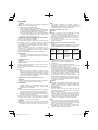
Specifi cations
Code
No.
Typr of
attaching
screw
Direction of
rotation
Size of
attaching
screw
6696454 Female screw
Counter-
clockwise
M10xP1.25-
LH
Applicable nylon cord
Cord diameter: Φ3.0 mm Length: 2 m
Cord diameter: Φ2.4 mm Length: 4 m
2. Precautions
○ The case must be securely attached to the cover.
○ Check the cover, case and other components for cracks
or other damage.
○ Check the case and button for wear.
If the wear limit mark (23) on the case is no longer visible
or there is a hole in the bottom (24) of the button, change
the new parts immediately. (Fig. 15)
○ The cutting head must be securely mounted to the unit’s
gear case/cutter case.
○ If the cutting head does not feed cutting line properly,
check that the nylon line and all components are properly
installed. Contact Hitachi Authorized Service Centers if
you need assistance.
WARNING
For Hitachi heads, use only fl exible, non-metallic line
recommended by the manufacturer. Never use wire or
wire ropes. They can break off and become a dangerous
projectile.
3. Installation (Fig. 16)
Insert the allen wrench (25) into the hole of the gear
case/cutter case in order to lock the drive shaft tube.
Install cutting head on gear case/cutter case of grass
trimmers/brush cutters. The mounting nut is left-hand-
threaded. Turn clockwise to loosen/counter-clockwise to
tighten.
NOTE
○ For curved drive shaft tube models, the mounting nut is
right-hand-threaded. Turn counter-clockwise to loosen/
clockwise to tighten.
○ Since the cutter holder cap is not used here, keep it for
when a metal blade is used, if so equipped.
4. Adjusting line length
Set the engine speed as low as possible and tap the
head on the ground. The nylon line will be drawn out
about 3 cm with each tap. (Fig. 17)
Also, you can extend the nylon line by hand but the
engine must be completely stopped. (Fig. 18)
Adjust the nylon line to the proper length of 11–14 cm
before each operation.
Installation of cutting blade (Fig. 19)
(If so equipped)
Insert the alien wrench (25) into the hole of the gear case in
order to lock the shaft.
Assemble in the following order: Cutter holder (A) (26),
blade (27), cutter holder (B) (28), nut cover (29).
Tighten the fi xing nut with the box wrench. Please note that
the cutter fi xing nut (30) has left-handed threads (clockwise
to loosen/ counter-clockwise to tighten).
NOTE
○ When installing cutter holder (B) (28), be sure to set
concave side upward.
○ When installing or removing a blade, make sure to wear
gloves and place the blade cover over the blade.
CAUTION
Check a nut cover (29) for wear or cracks before
operation. If any damage or wear is found, replace it, as
it is an article of consumption.
WARNING
○ When installing a cutting blade, make sure that there are
no cracks or any damage in it and that the cutting edges
are facing the correct direction.
○ Remove any surface grit from blade installation fi ttings
(cutter holder (A) (26), cutter holder (B) (28), nut
cover (29), nut (30)). Failure to do so may result in the
loosening of nuts.
○ The protrusion of the cutter holder (A) (26) may become
misaligned with the blade (27) while tightening nut
(30). Before operation, make sure the blade has been
properly installed. (Fig. 20)
○ Rotate the blade by hand and make sure there is no
rocking or abnormal noise. Rocking may cause abnormal
vibrations or result in the loosening of nuts.
OPERATING PROCEDURES
Engine oil
○ Always use the specifi ed engine oil (multigrade oil of
classifi cation SAE 10W-30). Insuffi cient engine oil or
using engine oil other than the specifi ed type may cause
breakdown of the unit.
Filling up with engine oil
○ Place the unit horizontally on a clean, fl at surface.
○ Remove the oil cap and check whether the engine oil
comes up to the mouth of the oil tank opening. (Fig. 21)
○ If the oil level is low or when using the unit for the fi rst
time, fi ll the tank with engine oil up to the mouth of the oil
tank opening.
○ If the engine oil is conspicuously dirty or discolored,
change the oil.
○ Tighten the oil cap securely after fueling.
○ When using the unit for the fi rst time, change the engine
oil after running the engine for approximately 10 hours.
Subsequently, change the oil after every 50 hours of
operation.
CAUTION
○ To avoid the risk of burn injuries, allow the engine to cool
thoroughly before changing the engine oil.
○ To prevent breakdown, ensure that no sand or dirt gets
into the tank while refueling.
Fuel
WARNING
○ Provide good ventilation, when fueling or handling fuel.
○ Fuel contains highly fl ammable and it is possible to get
the serious personal injury when inhaling or spilling on
your body. Always pay attention when handling fuel.
Always have good ventilation when handling fuel inside
building.
○ Always use branded 89 octane unleaded gasoline.

English
12
○ Do not use a mixture of gasoline and engine oil as this
may lead to starter failure or power reduction.
Fueling
WARNING
○ Always shut off the engine and let it cool for a few
minutes before refueling.
Do not smoke or bring fl ames or sparks near the fueling
site.
○ Slowly open the fuel tank, when fi lling up with fuel, so
that possible over-pressure disappears.
○ Tighten the fuel tank cap carefully, after fueling.
○ Always move the unit at least 3 m from the fueling area
before starting.
○ Always wash any spilled fuel from clothing immediately
with soap.
○ Be sure to check any fuel leakage after refueling.
○ Before fueling, in order to remove static electricity from
the main body, the fuel container and the operator,
please touch the ground that is slightly damp.
Before fueling, clean the tank cap area carefully, to ensure
that no dirt falls into the tank.
Starting
CAUTION
Before starting, make sure the cutting attachment does
not touch anything.
(1) Starting the cold engine
1. Set ignition switch (31) to ON position. (Fig. 22)
2. Push priming bulb (32) several times so that fuel fl ows
through return pipe (33). (Fig. 23)
3. Set choke lever (34) to START position (closed) (A).
(Fig. 24)
4. Pull recoil starter briskly, taking care to keep the handle
in your grasp and not allowing it to snap back. (Fig. 25)
5. When you hear the engine want to start, return choke
lever to RUN position (open) (B). (Fig. 24)
6. Pull recoil starter briskly again. (Fig. 25)
NOTE
If engine does not start, repeat procedures from 2 to 5.
7. Then allow the engine about 2–3 minutes to warm up
before subjecting it to any load.
8. Check that the cutting attachment does not rotate when
the engine is idling.
(2) Starting the warm engine
Use only 1, 6 and 8 of the starting procedure for a cold
engine.
If the engine does not start, use the same starting
procedure as for a cold engine.
Cutting
WARNING
○ Always use the harness (if so equipped) and wear the
proper attire and protective equipment when operating
the unit. (Fig. 26)
○ Keep others including children, animals, bystanders and
helpers outside the 15 m hazard zone. Stop the engine
immediately if you are approached. (Fig. 27)
○ When grass or vines wrap around attachment, stop
engine and attachment and remove them. Continuing
operation with grass or vines wrapped around the
attachment may result in damages such as early
abrasion of the clutch.
CAUTION
Use and points of caution will vary depending on the type
of cutting attachment. For safe use, make sure to follow
the instructions and guidelines provided with each type.
NOTE
○ Press the quick release button or pull emergency release
fl ap (If so equipped) in the event of emergency. (Fig. 28)
○ Use in accordance with local laws and regulations.
(1) Using a semi-auto cutting head
○ Set the engine at high speed when using this attachment.
○ Cut grass from left to right. The cut grass will be
discharged away from the body, minimizing transfer to
your clothes. (Fig. 29)
○ With nylon cord, use about 2 cm of the end of the cord
to cut grass. Using the full length of the cord will reduce
rotation speed and make cutting diffi cult.
NOTE
Automatically feeds more nylon cutting line when it is
tapped at low rpm (not greater than 4500 min
-1
).
WARNING
○ This product is equipped with a line limiter that will
automatically cut any excess cord. When operating the
unit, do not remove the guard or line limiter.
As the resistance is greater for nylon cords as opposed
to blades, mishandling could increase engine load and
result in damage.
○ Do not use with the engine set at low speeds. If the
engine speed is low, grass may wrap around the
attachment, causing the clutch to slip which could result
in clutch abrasion.
○ With nylon cord cutters, always use over 15 cm of cord.
If the length of the cord is too short, rotation speed will
increase and may cause damage to the nylon cord
cutter.
(2) Using a blade
○ Adjust engine speed according to the resistance of the
grass. For soft grass, use low speeds, For tough clumps
of grass, use high speeds.
○ Cut grass from right to left, using the left side of the blade
to cut. (Fig. 30)
○ Slightly tilting the blade to the left while cutting will pile
the cut grass to the left, making collection easy.
NOTE
Excessively increasing rotation speed may cause
increased blade wear, vibration and noise. It will also
result in increased fuel consumption.
WARNING
○ Blade thrust may occur when the spinning blade contacts
a solid object in the critical area.
A dangerous reaction may occur causing the entire unit
and operator to be thrust violently. This reaction is called
blade thrust. As a result, the operator may lose control
of the unit which may cause serious or fatal injury. Blade
thrust is more likely to occur in areas where it is diffi cult
to see the material to be cut.
○ If cutting attachment should strike against stones or
other debris, stop the engine and make sure that the
attachment and related parts are undamaged.
Stopping (Fig. 31)
Decrease engine speed and run at an idle for a few minutes,
then turn off ignition switch (31).
WARNING
A cutting attachment can injure while it continues to spin
after the engine is stopped or power control is released.
When the unit is turned off , make sure the cutting
attachment has stopped before the unit is set down.

English
13
MAINTENANCE
MAINTENANCE, REPLACEMENT OR REPAIR OF THE
EMISSION CONTROL DEVICES AND SYSTEMS MAY
BE PERFORMED BY ANY NON-ROAD ENGINE REPAIR
ESTABLISHMENT OR INDIVIDUAL.
Carburetor adjustment (Fig. 32)
WARNING
○ The cutting attachment may be spinning during
carburetor adjustments.
○ Never start the engine without the complete clutch cover
and tube assembled! Otherwise the clutch can come
loose and cause personal injuries.
In the carburetor, fuel is mixed with air. When the engine is
test run at the factory, the carburetor is adjusted. A further
adjustment may be required, according to climate and
altitude. The carburetor has one adjustment possibility:
T = Idle speed adjustment screw.
Idle speed adjustment (T)
Check that the air fi lter is clean. When the idle speed is
correct, the cutting attachment will not rotate. If adjustment
is required, close (clockwise) the T-screw, with the engine
running, until the cutting attachment starts to rotate. Open
(counter-clockwise) the screw until the cutting attachment
stops. You have reached the correct idle speed when the
engine runs smoothly in all positions well below the rpm
when the cutting attachment starts to rotate.
If the cutting attachment still rotates after idle speed
adjustment, contact Hitachi Authorized Service Centers.
NOTE
Standard Idle rpm is 2500 – 3500 min
-1
.
WARNING
When the engine is idling the cutting attachment must
under no circumstances rotate.
Changing the engine oil
Dirty engine oil will considerably reduce the service life of the
engine. Check and change the engine oil regularly.
CAUTION
○ To avoid the risk of burn injuries, allow the engine to cool
thoroughly before changing the engine oil.
○ To prevent breakdown, ensure that no sand or dirt gets
into the tank while refueling.
When to change the oil: When fi rst using the unit, after
approximately 10 hours of operation or after 1 month,
whichever occurs earlier; subsequently, after every 50 hours
of operation or every 6 months, whichever occurs earlier.
Specifi ed engine oil: Multigrade oil of classifi cation SAE 10W-
30
Engine oil capacity: 80 ml
1. Turn off the ignition switch.
2. Check that the fuel cap is securely tightened.
3. Remove the oil cap, tilt the unit so that the oil tank
opening is on the underside and drain the engine oil into
a container. (Fig. 33)
4. When all the engine oil has been drained, place the unit
horizontally on a clean, fl at surface.
5. Fill the oil tank with engine oil up to the mouth of the oil
tank opening. (Fig. 21)
6. Tighten the oil cap securely by hand.
NOTE
○ Do not dispose of waste engine oil with garbage or into
the ground.
Dispose of the oil according to the specifi ed method in
your area.
If you are unsure, contact the retailer where the oil was
purchased.
○ Fill the oil tank with the specifi ed amount of engine oil.
Too much or too little engine oil may result in engine
breakdown.
○ Engine oil deteriorates naturally even if unused.
Change the engine oil regularly.
Air fi lter (Fig. 34)
The air fi lter (35) must be cleaned from dust and dirt in order
to avoid:
○ Carburetor malfunctions.
○ Starting problems.
○ Engine power reduction.
○ Unnecessary wear on the engine parts.
○ Abnormal fuel consumption.
Clean the air fi lter daily or more often if working in
exceptionally dusty areas.
Cleaning the air fi lter
Remove the air fi lter cover and the fi lter (35). Rinse it in warm
soap suds. Check that the fi lter is dry before reassembly. An
air fi lter that has been used for some time cannot be cleaned
completely. Therefore, it must regularly be replaced with a
new one. A damaged fi lter must always be replaced.
Fuel fi lter (Fig. 35)
Check the fuel fi lter occasionally for clogging as insuffi cient
fuel fl ow could aff ect engine speed.
Drain all fuel from fuel tank and pull fuel fi lter (36) from tank.
Rinse it in warm water with detergent.
Rinse thoroughly until all traces of detergent are eliminated.
Squeeze, away excess water and allow element to air dry.
NOTE
If the fuel fi lter (36) is hard due to excessive dirt buildup,
replace it.
Spark plug (Fig. 36)
The spark plug condition is infl uenced by:
○ An incorrect carburetor setting.
○ A dirty air fi lter.
○ Hard running conditions (such as cold weather).
○ Too much engine oil
These factors cause deposits on the spark plug electrodes,
which may result in malfunction and starting diffi culties. If
the engine is low on power, diffi cult to start or runs poorly at
idling speed, always check the spark plug fi rst.
If the spark plug is dirty, clean it and check the electrode
gap. Re-adjust if necessary. The correct gap is 0.6 mm. The
spark plug should be replaced after about 100 operation
hours or earlier if the electrodes are badly eroded.
NOTE
In some areas, local law requires using a resistor spark
plug to suppress ignition signals. If this machine was
originally equipped with resistor spark plug, use same
type of spark plug for replacement.
Gear case (Fig. 37)
Check gear case or angle gear for grease level about every
50 hours of operation by removing the grease fi ller plug on
the side of gear case.
If no grease can be seen on the fl anks of the gears, fi ll the
gear case with quality lithium based multipurpose grease up
to 3/4. Do not completely fi ll the gear case.
CAUTION
○ Make sure to remove any dirt or grit when attaching the
plug to its original position.
○ Before attempting inspection or maintenance of the gear
case, make sure the case has cooled.

English
14
Semi-auto cutting head
Nylon line replacement
1. Remove the case (37) by fi rmly pushing inward the
locking tabs with your thumbs as shown in Fig. 38.
2. After removing the case, take out the reel and discard
the remaining line.
3. Fold the new nylon line unevenly in half as shown in
picture.
Hook the U-shaped end of the nylon line into the groove
(38) on the center partition of the reel.
Wind both halves of the line on the reel in the same
direction, keeping each half of the line on its own side of
the partition. (Fig. 39)
4. Push each line into the stopper holes (39), leaving the
loose ends approx. 10 cm in length. (Fig. 40)
5. Insert both loose ends of the line through the cord guide
(40) when placing the reel in the case. (Fig. 41)
NOTE
When placing a reel in the case, try to line up the stopper
holes (39) with the cord guide (40) for easier line release
later.
6. Place the cover over the case so that the cap locking
tabs (41) on the case meet the long holes (42) on the
cover. Then push the case securely until it clicks into
place. (Fig. 42)
7. The initial cutting line length should be approx. 11–14 cm
and should be equal on both sides. (Fig. 43)
Blade (Fig. 44)
WARNING
Wear protective gloves when handling or performing
maintenance on the blade.
○ Use a sharp blade. A dull blade is more likely to snag and
thrust.
Replace the fastening nut if it is damaged and hard to
tighten.
○ When replacing blade, purchase one recommended by
Hitachi, with a 25.4 mm (one inch) fi tting hole.
○ In the case of a 3 or 4 tooth blade (43), it can be used on
either side.
○ Use the correct blade for the type of work.
○ When replacing blades, use appropriate tools.
○ When cutting edges become dull, re-sharpen or fi le
as shown in the illustration. Incorrect sharpening may
cause excessive vibration.
○ Discard blades that are bent, warped, cracked, broken
or damaged in any way.
NOTE
When sharpening blade it is important to maintain an
original shape of radius at the base of the tooth to avoid
cracking.
For long-term storage
Drain all fuel from the fuel tank and drain all engine oil. Start
and let engine run until it stops. Repair any damage which
has resulted from use. Clean the unit with a clean rag, or the
use of high pressure air hose. Put a few drops of engine oil
into the cylinder through the spark plug hole, and spin the
engine over several times to distribute oil.
Cover the unit and store it in a dry area.
Maintenance schedule
Below you will fi nd some general maintenance instructions.
For further information please contact Hitachi Authorized
Service Centers.
Daily maintenance
○ Clean the exterior of the unit.
○ Check that the harness is undamaged.
○ Check the cutting attachment guard for damage or
cracks. Change the guard in case of impacts or cracks.
○ Check that the cutting attachment is properly centered,
sharp, and without cracks. An off -center cutting
attachment induces heavy vibrations that may damage
the unit.
○ Check that the cutting attachment nut is suffi ciently
tightened.
○ Make sure that the blade cover is undamaged and that it
can be securely fi tted.
○ Check that nuts and screws are suffi ciently tightened.
○ Check the volume and condition of the engine oil.
○ Check that the unit is undamaged and free of defects.
Weekly maintenance
○ Check the starter, especially the cord and return spring.
○ Clean the exterior of the spark plug.
○ Remove the spark plug and check the electrode gap.
Adjust it to 0.6 mm, or change the spark plug.
○ Check that the angle gear is fi lled with grease up to 3/4.
○ Clean the air fi lter.
Monthly maintenance
○ Rinse the fuel tank with gasoline.
○ Clean the exterior of the carburetor and the space
around it.
○ Clean the fan and the space around it.
SELECTING ACCESSORIES
The accessories of this machine are listed on page 287.

English
15
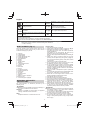
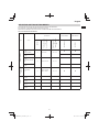
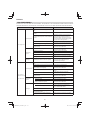
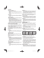
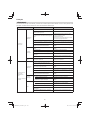
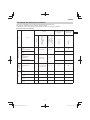
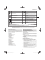
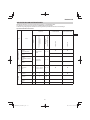
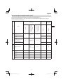
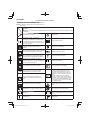
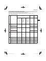
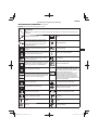
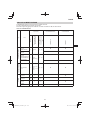
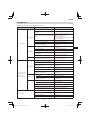
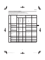
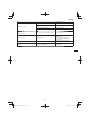
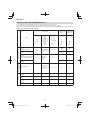
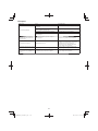
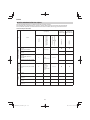
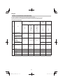
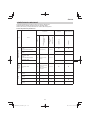
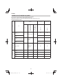
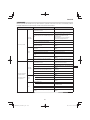
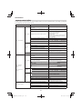
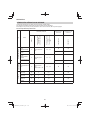
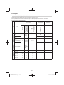
SELECTING CUTTING ATTACHMENTS
Recommended accessories for each model are presented in the table below.
For purchases, contact Hitachi Authorized Service Centers.
Please check carefully as those accessories not marked with “
●” cannot be attached.
List of recommended accessories
Type Name
Specifi cation LOOP HANDLE BIKE HANDLE
Diameter
Feed System Adapter
or
No. of Teeth (Blade)
Blade Thickness (mm)
or
Trimmer line Diameter
(mm)
CG25EUP2 (L)
CG25EUP2
ALUMINUM HEADS
NYLON HEAD
CH-100
(W/NYLON LINE)
4” Pre-Cut Line 2.2 – 3.0
●●
NYLON HEAD
CH-100
●●
NYLON HEAD
CH-300
(W/CUTTER HOLDER
CAP)
5” Manual line feed 2.2 – 2.7
NYLON HEAD
CH-300
TAP & GO NYLON
HEADS
NYLON HEAD
BF-5
5”
L M10 x 1.25 Nut
L M8 x 1.25 Nut
2.2 – 3.0 ●●
BLADES
BLADE
B3/10/2.0
10” 3 2.0 ●
BLADE
B3/12/3.0
12” 3 3.0
BLADE
B4/9/1.6
9” 4 1.6 ●
BLADE
B4/10/1.6
10” 4 1.6 ●

English
16
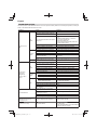
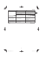
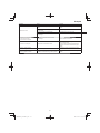
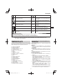
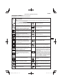
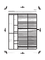
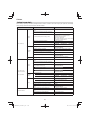
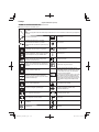
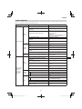
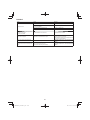
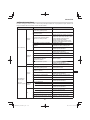
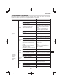
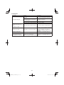
TROUBLESHOOTING
Use the inspections in the table below if the tool does not operate normally. If this does not remedy the problem, consult your
dealer or the Hitachi Authorized Service Center.
Condition Cause Remedy
Engine does not
start
Fuel
system
Fuel tank is empty or fuel level is low Fill the fuel tank
Fuel tank contains old fuel (off ensive
odor)
Replace with new fuel
Too much fuel is absorbed and spark
plug is wet
1. Disconnect the spark plug and allow to
dry
2. Pull the starter handle 5 or 6 times to
remove the surplus fuel
3. Attach the spark plug
4. Set the choke lever to RUN position and
pull the starter handle
Fuel fi lter is clogged with dirt Clean the fuel fi lter
Fuel pipe is bent or disconnected Ensure that the fuel fl ows smoothly
Carburetor malfunction Contact Hitachi Authorized Service Centers
Electrical
system
Stop switch lead has short-circuited Contact Hitachi Authorized Service Centers
Spark plug is dirty Replace or clean the spark plug
Electrode gap is too big Adjust the gap to 0.6mm
Poor connection between high tension
cable and spark plug
Reconnect
Electrical system malfunction Contact Hitachi Authorized Service Centers
Other
Muffl er exhaust port is clogged with
carbon
Contact Hitachi Authorized Service Centers
for repair
Engine starts
but cuts out
straightaway
Engine is apt to
cut out
Fuel
system
Fuel tank is empty or fuel level is low Fill the fuel tank
Fuel tank contains old fuel (off ensive
odor)
Replace with new fuel
Engine oil has not been added Contact Hitachi Authorized Service Centers
Choke lever is in START position Set the choke lever to RUN position
Air has got into fuel system Reconnect the fuel pipe or joint
Carburetor malfunction Contact Hitachi Authorized Service Centers
Electrical
system
Ignition failure
Spark plug failure Replace with new spark plug
Electrical system failure Contact Hitachi Authorized Service Centers
Other
Engine overheating
Wrong spark plug model
Replace with designated part
See “SPECIFICATIONS”
Dirty air cleaner Clean
Carbon clogging (muffl er exhaust port) Clean
Insuffi cient compression (piston, piston
ring, cylinder)
Contact Hitachi Authorized Service Centers
Abnormal vibration
Cutting attachment is not properly
installed
See “Installation of cutting attachment”
Handle, handle bracket or other
fastening part is loose
Check and tighten
Blade is bent or damaged Replace with new blade
Grass is wrapped round gear case Remove grass
Engine is running but cutting
attachment does not move
Movement is poor
Grass is wrapped round gear case Remove grass and dirt
Engine does not stop Stop switch failure
Set the choke lever to START position to
stop the engine
Cease use immediately and contact Hitachi
Authorized Service Centers

English
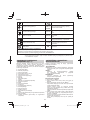
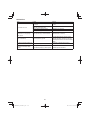
17
Condition Cause Remedy
Engine stops when throttle is
closed
Idle speed is too low Contact Hitachi Authorized Service Centers
Cutting attachment continues
rotating when throttle is closed
Idle speed is too high
Throttle wire is too taut
Contact Hitachi Authorized Service Centers

Deutsch
18
(Übersetzung der Original-Gebrauchsanweisung)
SYMBOLBEDEUTUNGEN
HINWEIS: Nicht alle Geräte sind mit diesen Symbolen versehen.
Symbole
WARNUNG
Die folgenden Symbole werden für dieses Gerät verwendet. Achten Sie darauf, diese vor der Verwendung zu
verstehen.
Rasentrimmer / Heckenschere Notfallstopp
Es ist wichtig, dass Sie sich mit den
nachfolgenden Vorsichtsmaßnahmen und
Warnungen vertraut machen und diese
befolgen. Unvorsichtige oder unsachgemäße
Handhabung des Geräts kann schwere oder
tödliche Verletzungen zur Folge haben.
Kraftstoff füllung
Lesen, verstehen und befolgen Sie alle
Warnungen und Anweisungen in dieser
Anleitung und am Gerät selbst.
Motorölfüllung
Bei Gebrauch des Geräts immer Gesichts-,
Kopf- und Gehörschutz tragen.
Einstellung des Leerlaufs
Wenn dieses Zeichen am Gerät angebracht ist,
keine starren Messer/Metallmesser verwenden.
Ansaugpumpe
Halten Sie alle Kinder, Zuschauer und Helfer
15 m vom Gerät entfernt. Falls sich jemand
nähert, den Motor und das Zubehör sofort
ausschalten.
Garantierter Schallleistungspegel
Auf hochgeschleuderte Gegenstände achten.
Ein Messerstoß ist möglich, wenn das rotierende
Messer im kritischen Bereich mit einem
massiven Gegenstand in Berührung kommt.
In diesem Fall kann es zu einer gefährlichen
Reaktion kommen, bei der das gesamte
Gerät und der Bediener einem heftigen Stoß
ausgesetzt werden.
Diese Reaktion wird als Messerstoß bezeichnet.
Das Resultat ist u.U., dass der Bediener die
Kontrolle über das Gerät verliert und schwere
oder lebensgefährliche Verletzungen davonträgt.
Messerstöße sind in Arbeitsbereichen, wo das
zu schneidende Vegetationsmaterial nur schwer
einsehbar ist, wahrscheinlicher.
min
-1
Zeigt die maximale Drehzahl der Welle an.
Verwenden Sie kein Schneidzubehör, dessen
Maximaldrehzahl unter diesem Wert liegt.
Handschuhe sind dann zu tragen, wenn
dies notwendig ist, z.B. bei der Montage der
Schneide-Ausrüstung.
Heiße Oberfl äche – Kontakt mit heißer
Oberfl äche kann zu schweren Verbrennungen
führen.
Rutschfestes Schuhwerk tragen, das guten Halt
bietet.
Das Heckenschneide-Zubehör kann für
Modelle mit diesem Aufkleber nicht verwendet
werden.
Choke – Betriebsposition (Off en)
Bezeichnet den Griff stangenplatz. Pfeile, die
den Grenzwert für die Griff position anzeigen.
Choke – Start Position (Geschlossen) Verschiebung
Ein/Start Zündkerze
Aus/Stopp
Idle
Leerlaufdrehzahl

Deutsch
19
Drehzahl der Ausgangswelle
L
pA, eq
ISO22868
Schalldruckpegel LpA nach ISO 22868
Entsprechung*
P
Max. Motorleistung
L
WA, Ra(M)
2000/14/EC
Gemessener Schalldruck-Leistungspegel LwA
nach 2000/14/EC
Hochdrehen
Kraftstoff tankvolumen
L
WA, Ra(G)
2000/14/EC
Garantierter Schalldruck-Leistungspegel LwA
nach 2000/14/EC
Hochdrehen
Motorölfassungsvermögen
a
hv, eq(F)
Vibrationspegel nach ISO 22867
Vorderer oder linker Griff / Entsprechung*
Trockengewicht
a
hv, eq(R)
Vibrationspegel nach ISO 22867
Hinterer oder rechter Griff / Entsprechung*
Schneide-Zubehör
K
Unsicherheit
Vor dem Gebrauch Ihres Geräts
• Bedienungsanleitung sorgfältig durchlesen.
• Montage und Einstellung der Schneide-Ausrüstung kontrollieren.
• Gerät starten und Vergasereinstellung prüfen. Siehe „WARTUNG“.
HINWEIS: Die entsprechenden Geräusch- / Vibrationspegel werden als zeitgewichtete Energiesumme für Geräusch- /
Vibrationspegel unter verschiedenen Arbeitsbedingungen mit folgender Zeitaufteilung berechnet:
* 1/2 Leerlauf, 1/2 Hochgedreht.
HINWEIS
Kennzeichnet nützliche Informationen für den
vorschriftsmäßigen Gebrauch.
Bedienersicherheit
○ Kopfschutz tragen (1). (Abb. 2)
○ Immer einen Gesichtsschutz oder Schutzbrille tragen
(2). (Abb. 2)
○ Vorschriftsmäßigen Gehörschutz tragen (3). (Abb. 2)
Über einen längeren Zeitraum Lärm ausgesetzt sein,
kann zu bleibenden Hörschäden führen.
Die Umgebung im Auge behalten. Auf Beistehende
achten, die unter Umständen ein Problem signalisieren.
Die Schutzbekleidung erst nach Abstellen des Motors
wieder ablegen.
○ Immer schwere, langärmlige Shirts tragen (4) und lange
Hosen (5) und rutschfeste Stiefel (6) und Handschuhe
(7). (Abb. 2)
Das Arbeiten mit lockerer Kleidung, Schmuck, kurzen
Hosen, Sandalen oder barfuß ist zu vermeiden.
Das Haar ist so zu sichern, dass es nicht bis zu den
Schultern herunterhängt.
○ Bedienen Sie das Gerät nicht, wenn Sie übermüdet
oder krank sind oder unter Alkohol-, Drogen- oder
Medikamenteneinfl uss stehen.
○ Bedienen Sie das Werkzeug nicht bei Nacht oder unter
schlechten Wetterbedingungen, wenn die Sicht schlecht
ist. Und bedienen Sie das Werkzeug nicht, wenn es
regnet oder unmittelbar, nachdem es geregnet hat.
Arbeiten auf rutschigem Untergrund kann zu einem
Unfall führen, wenn Sie Ihr Gleichgewicht verlieren.
○ Lassen Sie niemals ein Kind oder eine unerfahrene
Person die Maschine bedienen.
○ Starten Sie den Motor nicht, wenn leicht Entfl ammbares
wie trockenes Laub, Papierabfall oder Kraftstoff in der
Nähe sind.
○ Starten oder betreiben Sie denn Motor niemals innerhalb
geschlossener Räume oder in einem Gebäude.
Einatmen der Abgase kann den Tod zur Folge haben.
○ Halten Sie die Griff e frei von Öl und Kraftstoff .
○ Berühren Sie nicht die Schneide-Ausrüstung.
○ Fassen oder halten Sie das Gerät nicht an der
Schneideausrüstung.
WAS IST WAS? (Abb. 1)
Da dieses Handbuch für mehrere Modelle gilt, können die
Abbildungen gegebenenfalls von Ihrem Gerät abweichen.
Verwenden Sie die für Ihr Gerät geltenden Anweisungen.
A: Tankdeckel
B: Gaszug
C: Startergriff
D: Schutz Schneide-Zubehör
E: Schneide-Zubehör
F: Antriebswellenrohr
G: Griff
H: Aufhänger
I: Zündschalter
J: Gurtzeug
K: Gaszugsperre
L: Chokehebel
M: Motor
N: Getriebegehäuse
O: Öleinfülldeckel
P: Kombischlüssel
Q: Bedienungsanleitung
R: Schwenkkappe
S: Brille
T: Sechskantschlüssel
U: Spanner
V: Klingenabdeckung (je nach Ausstattung)
W: Motorabdeckung
X: Kabelbinder (je nach Ausstattung)
WARN- UND SICHERHEITSHINWEISE
Abschnitte, denen besondere Aufmerksamkeit gewidmet
werden sollte, werden durch folgende Wörter hervorgehoben:
WARNUNG
Kennzeichnet Anweisungen, deren Nichtbefolgung eine
schwere Verletzung oder den Tod zur Folge haben kann.
VORSICHT
Kennzeichnet Anweisungen, deren Nichtbefolgung eine
Verletzung oder Sachschaden zur Folge haben kann.

Deutsch
20
○ Beim Anbau oder Entfernen der Schneide-Ausrüstung
sollten Handschuhe getragen werden. Wird dies nicht
beachtet, kann es zu Verletzungen kommen.
○ Wenn das Gerät ausgeschaltet wird, achten Sie darauf,
dass die Schneide-Ausrüstung gestoppt hat, bevor Sie
das Gerät auf den Boden stellen.
○ Bei längerem Betrieb regelmäßig eine Pause
einlegen, als vorbeugende Maßnahme gegen die
Weißfi ngerkrankheit, die durch Vibrationen verursacht
wird.
WARNUNG
○
Bedienen Sie das Werkzeug immer mit geeigneter
Schutzausrüstung und -kleidung. Nichtbeachtung kann zu
Unfällen wie Verbrennungen und Verletzungen führen. (Abb. 2)
○ Berühren Sie während des Betriebs nicht den Bereich
der Zündkerze oder Hochspannung. Dadurch könnte es
zu einem elektrischen Schlag kommen.
○ Gestatten Sie Kindern nicht, sich während des Betriebs
in der Nähe des Werkzeugs aufzuhalten.
○ Berühren Sie während oder kurz nach dem Betrieb
nicht den Auspuff , Schalldämpfer oder das Abgasventil.
Dadurch könnte es zu Verbrennungen oder Verletzungen
kommen.
○ Antivibrationssysteme sind kein garantierter
Schutz gegen die Weißfi ngerkrankheit oder
Karpaltunnelsyndrom. Daher ist bei regelmäßigem
Dauereinsatz des Geräts der Zustand von Fingern
und Handwurzel aufmerksam zu beobachten. Falls
Symptome der obengenannten Krankheiten auftreten,
sofort einen Arzt aufsuchen.
○ Träger eines medizinischen elektrischen bzw.
elektronischen Geräts (Herzschrittmacher u. dgl.) sollten
sich vor dem Gebrauch eines Motorgeräts von Ihrem
Arzt sowie dem Hersteller des Geräts diesbezüglich
beraten lassen.
Geräte-/Maschinensicherheit
○ Das Gerät/die Maschine vor jedem Einsatz einer
eingehenden Kontrolle unterziehen. Beschädigte
Teile ersetzen. Das Gerät auf auslaufenden
Kraftstoff untersuchen und sicherstellen, dass alle
Befestigungsteile vorhanden und sicher angezogen
sind.
○ Ersetzen Sie Teile, die gerissen, gebrochen oder
anderweitig beschädigt sind, bevor Sie das Gerät/die
Maschine verwenden. Fehlerhafte Teile können das
Risiko von Unfällen erhöhen und zu einer Verletzung
führen.
○ Achten Sie darauf, dass der Schutz der Schneide-
Ausrüstung und das Gurtzeug korrekt befestigt sind.
Funktioniert nicht, wenn der Schutz der Schneide-
Ausrüstung und das Gurtzeug nicht korrekt befestigt
sind.
○ Halten Sie während der Vergasereinstellung andere
Personen fern.
○ Verwenden Sie nur Zubehör, das vom Hersteller für
dieses Gerät/diese Maschine empfohlen wurde.
○ Achten Sie vor der Inbetriebnahme darauf, dass keine
Werkzeuge wie der Einstellschlüssel oder Spanner noch
am Gerät befestigt sind.
WARNUNG
○ Bauen Sie das Gerät/die Maschine in keiner Weise um.
Das Gerät nur für die Zwecke verwenden, für die es
bestimmt ist.
○ Nichtautorisierter Umbau und/oder Zubehör können zu
schweren Verletzungen oder zum Tod des Bedieners
oder anderer Personen führen.
Kraftstoff sicherheit
○ Füllen Sie den Kraftstoff im Freien ein und achten Sie
darauf, dass keine Funken und kein off enes Feuer in der
Nähe vorhanden sind.
○ Verwenden Sie einen Behälter, der für Kraftstoff
zugelassen ist.
○ Gehen Sie mindestens 3 m von der Betankungsstelle
weg, bevor Sie den Motor starten.
○ Stoppen Sie den Motor, bevor Sie den Tankdeckel
entfernen. Entfernen Sie den Tankdeckel nicht während
des Betriebs.
○ Leeren Sie den Kraftstoff tank, bevor Sie das Gerät/die
Maschine einlagern. Es wird empfohlen, den Kraftstoff
nach jedem Einsatz abzulassen. Mit gefülltem Tank ist
das Gerät so zu lagern, dass kein Kraftstoff ausläuft.
WARNUNG
○ Kraftstoff ist leichtentzündlich oder kann explodieren
oder die Dämpfe eingeatmet werden, lassen Sie deshalb
besondere Sorgfalt walten, wenn Sie mit Kraftstoff
umgehen oder ihn einfüllen.
○ Rauchen Sie nicht und erlauben Sie anderen Personen
nicht das Rauchen in der Nähe des Geräts/der
Maschine oder während der Verwendung des Geräts/
der Maschine.
○ Wischen Sie vor dem Starten des Motors alle
Kraftstoff spritzer weg.
○ Gerät und Kraftstoff an einem Ort lagern, wo
Kraftstoff dämpfe nicht mit Funken oder off enen Flammen
von Wassererhitzern, Elektromotoren oder elektrischen
Schaltern, Öfen usw. in Berührung kommen können.
○ Wenn dieses Gerät in trockenen Bereichen verwendet
wird, achten Sie darauf, dass eine Feuerlöschausrüstung
bereit steht.
○ Wenn Sie den Motor zum Nachtanken abschalten,
lassen Sie das Gerät erst abkühlen, bevor Sie Kraftstoff
nachfüllen.
Schneidsicherheit
○ Schneiden Sie keine anderen Materialien außer Gras
und Hecken.
○ Inspizieren Sie vor jeder Verwendung den zu mähenden
Bereich.
Entfernen Sie Gegenstände, die hochgeschleudert
werden oder sich verfangen können.
Nicht in Bereichen mit Baumwurzeln oder Felsen
verwenden.
○ Tragen Sie zum Schutz der Atemwege eine Aerosol-
Schutzmaske, wenn Sie Gras schneiden, auf dem
Insektenvernichtungsmittel versprüht wurde.
○ Halten Sie andere Personen einschließlich Kinder,
Zuschauer und Helfer außerhalb der 15 m Gefahrenzone.
Den Motor sofort abstellen, wenn sich jemand nähert.
○ Seien Sie vorsichtig, da der Motorstart nach dem Ziehen
des Startgriff s verzögert auftreten kann.
○ Halten Sie den Motor immer auf Ihrer rechten
Körperseite.
○ Halten Sie das Gerät/die Maschine mit beiden Händen
fest.
○ Achten Sie auf sicheren Stand und Gleichgewicht. Nicht
zu weit vorbeugen.
Wenn Sie während der Arbeit das Gleichgewicht
verlieren, kann das zu einer Verletzung führen.
○ Halten Sie alle Körperteile vom Schalldämpfer und der
Schneide-Ausrüstung entfernt, wenn der Motor läuft.
○ Halten Sie die Schneide-Ausrüstung unterhalb Ihrer
Knie.
○ Seien Sie besonders vorsichtig beim Betrieb in
Bereichen mit Elektrokabeln oder Gasleitungen.
○ Verwenden Sie die Schneide-Ausrüstung nicht für
etwas anderes außer zum Schneiden von Gras oder
Hecken. Vermeiden Sie den Betrieb, wenn die Schneide-
Ausrüstung Wasser, wie Pfützen berühren oder sich in
die Erde eingraben könnte. Nichtbeachtung kann zu
Verletzungen oder Beschädigung des Geräts führen.
○ Vermeiden Sie längeren Betrieb bei niedriger Drehzahl,
bei der die Vibrationen stark sind. Dadurch kann es zu
einem Motorschaden kommen.
Pagina se încarcă ...
Pagina se încarcă ...
Pagina se încarcă ...
Pagina se încarcă ...
Pagina se încarcă ...
Pagina se încarcă ...
Pagina se încarcă ...
Pagina se încarcă ...
Pagina se încarcă ...
Pagina se încarcă ...
Pagina se încarcă ...
Pagina se încarcă ...
Pagina se încarcă ...
Pagina se încarcă ...
Pagina se încarcă ...
Pagina se încarcă ...
Pagina se încarcă ...
Pagina se încarcă ...
Pagina se încarcă ...
Pagina se încarcă ...
Pagina se încarcă ...
Pagina se încarcă ...
Pagina se încarcă ...
Pagina se încarcă ...
Pagina se încarcă ...
Pagina se încarcă ...
Pagina se încarcă ...
Pagina se încarcă ...
Pagina se încarcă ...
Pagina se încarcă ...
Pagina se încarcă ...
Pagina se încarcă ...
Pagina se încarcă ...
Pagina se încarcă ...
Pagina se încarcă ...
Pagina se încarcă ...
Pagina se încarcă ...
Pagina se încarcă ...
Pagina se încarcă ...
Pagina se încarcă ...
Pagina se încarcă ...
Pagina se încarcă ...
Pagina se încarcă ...
Pagina se încarcă ...
Pagina se încarcă ...
Pagina se încarcă ...
Pagina se încarcă ...
Pagina se încarcă ...
Pagina se încarcă ...
Pagina se încarcă ...
Pagina se încarcă ...
Pagina se încarcă ...
Pagina se încarcă ...
Pagina se încarcă ...
Pagina se încarcă ...
Pagina se încarcă ...
Pagina se încarcă ...
Pagina se încarcă ...
Pagina se încarcă ...
Pagina se încarcă ...
Pagina se încarcă ...
Pagina se încarcă ...
Pagina se încarcă ...
Pagina se încarcă ...
Pagina se încarcă ...
Pagina se încarcă ...
Pagina se încarcă ...
Pagina se încarcă ...
Pagina se încarcă ...
Pagina se încarcă ...
Pagina se încarcă ...
Pagina se încarcă ...
Pagina se încarcă ...
Pagina se încarcă ...
Pagina se încarcă ...
Pagina se încarcă ...
Pagina se încarcă ...
Pagina se încarcă ...
Pagina se încarcă ...
Pagina se încarcă ...
Pagina se încarcă ...
Pagina se încarcă ...
Pagina se încarcă ...
Pagina se încarcă ...
Pagina se încarcă ...
Pagina se încarcă ...
Pagina se încarcă ...
Pagina se încarcă ...
Pagina se încarcă ...
Pagina se încarcă ...
Pagina se încarcă ...
Pagina se încarcă ...
Pagina se încarcă ...
Pagina se încarcă ...
Pagina se încarcă ...
Pagina se încarcă ...
Pagina se încarcă ...
Pagina se încarcă ...
Pagina se încarcă ...
Pagina se încarcă ...
Pagina se încarcă ...
Pagina se încarcă ...
Pagina se încarcă ...
Pagina se încarcă ...
Pagina se încarcă ...
Pagina se încarcă ...
Pagina se încarcă ...
Pagina se încarcă ...
Pagina se încarcă ...
Pagina se încarcă ...
Pagina se încarcă ...
Pagina se încarcă ...
Pagina se încarcă ...
Pagina se încarcă ...
Pagina se încarcă ...
Pagina se încarcă ...
Pagina se încarcă ...
Pagina se încarcă ...
Pagina se încarcă ...
Pagina se încarcă ...
Pagina se încarcă ...
Pagina se încarcă ...
Pagina se încarcă ...
Pagina se încarcă ...
Pagina se încarcă ...
Pagina se încarcă ...
Pagina se încarcă ...
Pagina se încarcă ...
Pagina se încarcă ...
Pagina se încarcă ...
Pagina se încarcă ...
Pagina se încarcă ...
Pagina se încarcă ...
Pagina se încarcă ...
Pagina se încarcă ...
Pagina se încarcă ...
Pagina se încarcă ...
Pagina se încarcă ...
Pagina se încarcă ...
Pagina se încarcă ...
Pagina se încarcă ...
Pagina se încarcă ...
Pagina se încarcă ...
Pagina se încarcă ...
Pagina se încarcă ...
Pagina se încarcă ...
Pagina se încarcă ...
Pagina se încarcă ...
Pagina se încarcă ...
Pagina se încarcă ...
Pagina se încarcă ...
Pagina se încarcă ...
Pagina se încarcă ...
Pagina se încarcă ...
Pagina se încarcă ...
Pagina se încarcă ...
Pagina se încarcă ...
Pagina se încarcă ...
Pagina se încarcă ...
Pagina se încarcă ...
Pagina se încarcă ...
Pagina se încarcă ...
Pagina se încarcă ...
Pagina se încarcă ...
Pagina se încarcă ...
Pagina se încarcă ...
Pagina se încarcă ...
Pagina se încarcă ...
Pagina se încarcă ...
Pagina se încarcă ...
Pagina se încarcă ...
Pagina se încarcă ...
Pagina se încarcă ...
Pagina se încarcă ...
Pagina se încarcă ...
Pagina se încarcă ...
Pagina se încarcă ...
Pagina se încarcă ...
Pagina se încarcă ...
Pagina se încarcă ...
Pagina se încarcă ...
Pagina se încarcă ...
Pagina se încarcă ...
Pagina se încarcă ...
Pagina se încarcă ...
Pagina se încarcă ...
Pagina se încarcă ...
Pagina se încarcă ...
Pagina se încarcă ...
Pagina se încarcă ...
Pagina se încarcă ...
Pagina se încarcă ...
Pagina se încarcă ...
Pagina se încarcă ...
Pagina se încarcă ...
Pagina se încarcă ...
Pagina se încarcă ...
Pagina se încarcă ...
Pagina se încarcă ...
Pagina se încarcă ...
Pagina se încarcă ...
Pagina se încarcă ...
Pagina se încarcă ...
Pagina se încarcă ...
Pagina se încarcă ...
Pagina se încarcă ...
Pagina se încarcă ...
Pagina se încarcă ...
Pagina se încarcă ...
Pagina se încarcă ...
Pagina se încarcă ...
Pagina se încarcă ...
Pagina se încarcă ...
Pagina se încarcă ...
Pagina se încarcă ...
Pagina se încarcă ...
Pagina se încarcă ...
Pagina se încarcă ...
Pagina se încarcă ...
Pagina se încarcă ...
Pagina se încarcă ...
Pagina se încarcă ...
Pagina se încarcă ...
Pagina se încarcă ...
Pagina se încarcă ...
Pagina se încarcă ...
Pagina se încarcă ...
Pagina se încarcă ...
Pagina se încarcă ...
Pagina se încarcă ...
Pagina se încarcă ...
Pagina se încarcă ...
Pagina se încarcă ...
Pagina se încarcă ...
Pagina se încarcă ...
Pagina se încarcă ...
Pagina se încarcă ...
Pagina se încarcă ...
Pagina se încarcă ...
Pagina se încarcă ...
Pagina se încarcă ...
Pagina se încarcă ...
Pagina se încarcă ...
Pagina se încarcă ...
Pagina se încarcă ...
Pagina se încarcă ...
Pagina se încarcă ...
Pagina se încarcă ...
Pagina se încarcă ...
Pagina se încarcă ...
Pagina se încarcă ...
Pagina se încarcă ...
Pagina se încarcă ...
Pagina se încarcă ...
Pagina se încarcă ...
Pagina se încarcă ...
Pagina se încarcă ...
Pagina se încarcă ...
Pagina se încarcă ...
Pagina se încarcă ...
Pagina se încarcă ...
Pagina se încarcă ...
Pagina se încarcă ...
Pagina se încarcă ...
Pagina se încarcă ...
Pagina se încarcă ...
Pagina se încarcă ...
Pagina se încarcă ...
Pagina se încarcă ...
Pagina se încarcă ...
Pagina se încarcă ...
Pagina se încarcă ...
-
 1
1
-
 2
2
-
 3
3
-
 4
4
-
 5
5
-
 6
6
-
 7
7
-
 8
8
-
 9
9
-
 10
10
-
 11
11
-
 12
12
-
 13
13
-
 14
14
-
 15
15
-
 16
16
-
 17
17
-
 18
18
-
 19
19
-
 20
20
-
 21
21
-
 22
22
-
 23
23
-
 24
24
-
 25
25
-
 26
26
-
 27
27
-
 28
28
-
 29
29
-
 30
30
-
 31
31
-
 32
32
-
 33
33
-
 34
34
-
 35
35
-
 36
36
-
 37
37
-
 38
38
-
 39
39
-
 40
40
-
 41
41
-
 42
42
-
 43
43
-
 44
44
-
 45
45
-
 46
46
-
 47
47
-
 48
48
-
 49
49
-
 50
50
-
 51
51
-
 52
52
-
 53
53
-
 54
54
-
 55
55
-
 56
56
-
 57
57
-
 58
58
-
 59
59
-
 60
60
-
 61
61
-
 62
62
-
 63
63
-
 64
64
-
 65
65
-
 66
66
-
 67
67
-
 68
68
-
 69
69
-
 70
70
-
 71
71
-
 72
72
-
 73
73
-
 74
74
-
 75
75
-
 76
76
-
 77
77
-
 78
78
-
 79
79
-
 80
80
-
 81
81
-
 82
82
-
 83
83
-
 84
84
-
 85
85
-
 86
86
-
 87
87
-
 88
88
-
 89
89
-
 90
90
-
 91
91
-
 92
92
-
 93
93
-
 94
94
-
 95
95
-
 96
96
-
 97
97
-
 98
98
-
 99
99
-
 100
100
-
 101
101
-
 102
102
-
 103
103
-
 104
104
-
 105
105
-
 106
106
-
 107
107
-
 108
108
-
 109
109
-
 110
110
-
 111
111
-
 112
112
-
 113
113
-
 114
114
-
 115
115
-
 116
116
-
 117
117
-
 118
118
-
 119
119
-
 120
120
-
 121
121
-
 122
122
-
 123
123
-
 124
124
-
 125
125
-
 126
126
-
 127
127
-
 128
128
-
 129
129
-
 130
130
-
 131
131
-
 132
132
-
 133
133
-
 134
134
-
 135
135
-
 136
136
-
 137
137
-
 138
138
-
 139
139
-
 140
140
-
 141
141
-
 142
142
-
 143
143
-
 144
144
-
 145
145
-
 146
146
-
 147
147
-
 148
148
-
 149
149
-
 150
150
-
 151
151
-
 152
152
-
 153
153
-
 154
154
-
 155
155
-
 156
156
-
 157
157
-
 158
158
-
 159
159
-
 160
160
-
 161
161
-
 162
162
-
 163
163
-
 164
164
-
 165
165
-
 166
166
-
 167
167
-
 168
168
-
 169
169
-
 170
170
-
 171
171
-
 172
172
-
 173
173
-
 174
174
-
 175
175
-
 176
176
-
 177
177
-
 178
178
-
 179
179
-
 180
180
-
 181
181
-
 182
182
-
 183
183
-
 184
184
-
 185
185
-
 186
186
-
 187
187
-
 188
188
-
 189
189
-
 190
190
-
 191
191
-
 192
192
-
 193
193
-
 194
194
-
 195
195
-
 196
196
-
 197
197
-
 198
198
-
 199
199
-
 200
200
-
 201
201
-
 202
202
-
 203
203
-
 204
204
-
 205
205
-
 206
206
-
 207
207
-
 208
208
-
 209
209
-
 210
210
-
 211
211
-
 212
212
-
 213
213
-
 214
214
-
 215
215
-
 216
216
-
 217
217
-
 218
218
-
 219
219
-
 220
220
-
 221
221
-
 222
222
-
 223
223
-
 224
224
-
 225
225
-
 226
226
-
 227
227
-
 228
228
-
 229
229
-
 230
230
-
 231
231
-
 232
232
-
 233
233
-
 234
234
-
 235
235
-
 236
236
-
 237
237
-
 238
238
-
 239
239
-
 240
240
-
 241
241
-
 242
242
-
 243
243
-
 244
244
-
 245
245
-
 246
246
-
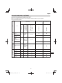 247
247
-
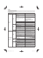 248
248
-
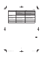 249
249
-
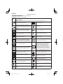 250
250
-
 251
251
-
 252
252
-
 253
253
-
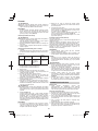 254
254
-
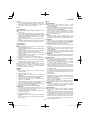 255
255
-
 256
256
-
 257
257
-
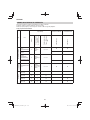 258
258
-
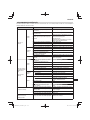 259
259
-
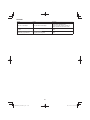 260
260
-
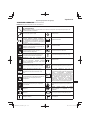 261
261
-
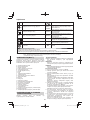 262
262
-
 263
263
-
 264
264
-
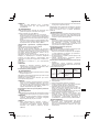 265
265
-
 266
266
-
 267
267
-
 268
268
-
 269
269
-
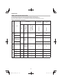 270
270
-
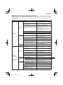 271
271
-
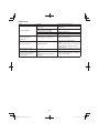 272
272
-
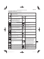 273
273
-
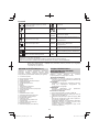 274
274
-
 275
275
-
 276
276
-
 277
277
-
 278
278
-
 279
279
-
 280
280
-
 281
281
-
 282
282
-
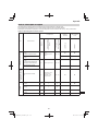 283
283
-
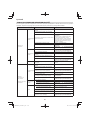 284
284
-
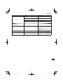 285
285
-
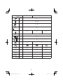 286
286
-
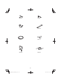 287
287
-
 288
288
-
 289
289
-
 290
290
-
 291
291
-
 292
292


Hikoki CG 25EUP2 Manual de utilizare
- Tip
- Manual de utilizare
- Acest manual este potrivit și pentru
în alte limbi
- slovenčina: Hikoki CG 25EUP2 Používateľská príručka
Lucrări conexe
Alte documente
-
Stiga B 26 D Instrucțiuni de utilizare
-
Ransomes USAG004 / USAD004 / 62706 Manualul proprietarului
-
Stiga Combi SU1066HQ Manual de utilizare
-
Ransomes HF600 Manualul proprietarului
-
Mountfield 1330M Instrucțiuni de utilizare
-
Hitachi CG 40EAS (P) Handling Instructions Manual
-
-
-
Ryobi rbl30bpt Manual de utilizare
-