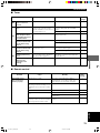
Yamaha DVX-S100 Manualul proprietarului
- Categorie
- DVD playere
- Tip
- Manualul proprietarului

DVD HOME THEATER SOUND SYSTEM
SYSTEME HOME CINEMA DVD AUDIO/VIDEO
DVX-S100
DVX-S100: DVR-S100 + NX-S100S + NX-S100C + SW-S100
OWNER’S MANUAL
MODE D’EMPLOI
BEDIENUNGSANLEITUNG
BRUKSANVISNING
MANUALE DI ISTRUZIONI
MANUAL DE INSTRUCCIONES
GEBRUIKSAANWIJZING
BG

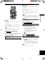
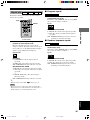
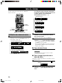
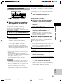
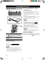
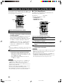
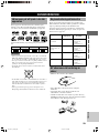
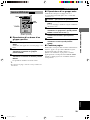
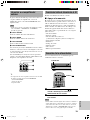
CAUTION
1 To assure the finest performance, please read this manual
carefully. Keep it in a safe place for future reference.
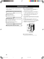
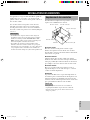
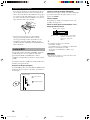
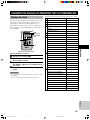
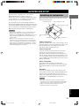
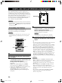
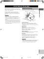
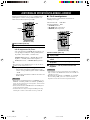
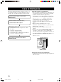
2 Install this sound system in a well ventilated, cool, dry, clean
place with at least 10 cm on the top, 10 cm on the left and
right, and 10 cm at the back of DVR-S100, and 20 cm on the
top, 10 cm on the left and right, and 10 cm at the back of
SW-S100 — away from direct sunlight, heat sources,
vibration, dust, moisture, and/or cold.
3 Locate this unit away from other electrical appliances,
motors, or transformers to avoid humming sounds. To
prevent fire or electrical shock, do not place this unit where
it may get exposed to dripping or splashing, and never put
any objects filled with liquids, such as vases, on the top of
the unit.
4 Do not expose this unit to sudden temperature changes from
cold to hot, and do not locate this unit in a environment with
high humidity (i.e. a room with a humidifier) to prevent
condensation inside this unit, which may cause an electrical
shock, fire, damage to this unit, and/or personal injury.
5 Avoid installing this unit in a place where foreign objects
and liquid might fall. It might cause a fire, damage to this
unit and/or personal injury. Do not place the following
objects on this unit:
– Other components, as they may cause damage and/or
discoloration on the surface of this unit.
– Burning objects (i.e. candles), as they may cause fire,
damage to this unit, and/or personal injury.
– Containers with liquid in them, as they may cause
electrical shock to the user and/or damage to this unit.
6 Do not cover this unit with a newspaper, tablecloth, curtain,
etc. in order not to obstruct heat radiation. If the temperature
inside this unit rises, it may cause fire, damage to this unit,
and/or personal injury.
7 Do not plug in this unit to a wall outlet until all connections
are complete.
8 Do not operate this unit upside-down. It may overheat,
possibly causing damage.
9 Do not use force on switches, knobs and/or cords.
10 When disconnecting the power cord from the wall outlet,
grasp the plug; do not pull the cord.
11 Do not clean this unit with chemical solvents; this might
damage the finish. Use a clean, dry cloth.
12 Only voltage specified on this unit must be used. Using this
unit with a higher voltage than specified is dangerous and
may cause fire, damage to this unit, and/or personal injury.
YAMAHA will not be held responsible for any damage
resulting from use of this unit with a voltage other than
specified.
13 To prevent damage by lightning, disconnect the power cord
from the wall outlet during an electrical storm.
14 Take care of this unit so that no foreign objects and/or liquid
drops inside this unit.
15 Do not attempt to modify or fix this unit. Contact qualified
YAMAHA service personnel when any service is needed.
The cabinet should never be opened for any reasons.
16 When not planning to use this unit for long periods of time
(i.e. vacation), disconnect the AC power plug from the wall
outlet.
17 Be sure to read the “TROUBLESHOOTING” section on
common operating errors before concluding that this unit is
faulty.
18 Before moving this unit, press STANDBY/ON to set this
unit in the standby mode, and disconnect the AC power plug
from the wall outlet.
CAUTION: READ THIS BEFORE OPERATING YOUR UNIT.
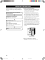
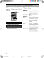
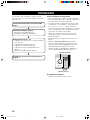
19 VOLTAGE SELECTOR (General model only)
The VOLTAGE SELECTOR on the rear panel of this unit
must be set for your local main voltage BEFORE plugging
into the AC main supply.
Voltages are 220/240 V AC, 50 Hz.
This unit is not disconnected from the AC power source as
long as it is connected to the wall outlet, even if this unit
itself is turned off. This state is called the standby mode. In
this state, this unit is designed to consume a very small
quantity of power.
■ For U.K. customers
If the socket outlets in the home are not suitable for the plug
supplied with this appliance, it should be cut off and an
appropriate 3 pin plug fitted. For details, refer to the instructions
described below.
Note
• The plug severed from the mains lead must be destroyed, as a
plug with bared flexible cord is hazardous if engaged in a live
socket outlet.
■ Special Instructions for U.K.
Model
IMPORTANT
THE WIRES IN MAINS LEAD ARE COLOURED IN
ACCORDANCE WITH THE FOLLOWING CODE:
Blue: NEUTRAL
Brown: LIVE
As the colours of the wires in the mains lead of this apparatus
may not correspond with the coloured markings identifying
the terminals in your plug, proceed as follows:
The wire which is coloured BLUE must be connected to the
terminal which is marked with the letter N or coloured
BLACK. The wire which is coloured BROWN must be
connected to the terminal which is marked with the letter L or
coloured RED.
Making sure that neither core is connected to the earth
terminal of the three pin plug.
DANGER
Visible laser radiation when open. Avoid direct exposure to
beam.
When this unit is plugged to the wall outlet, do not place your
eyes close to the opening of the disc tray and other openings to
look into inside.
The laser component in this product is capable of emitting
radiation exceeding the limit for Class 1.
The name plate is located on the bottom of the unit.
102_S100_Cau(GB) 02.3.22, 4:22 PM2

1
English
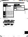
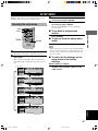
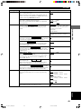
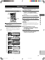
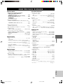
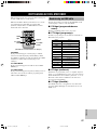
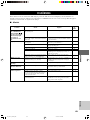
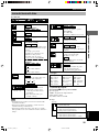
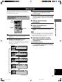
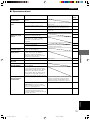
CONTENTS
INTRODUCTION
FEATURES .......................................................................... 2
CHECKING THE ACCESSORIES ................................... 3
INSTALLING BATTERIES IN THE REMOTE
CONTROL ........................................................................... 3
CONTROLS AND FUNCTIONS ....................................... 4
Front panel ......................................................................... 4
Remote control (AMP mode) ............................................ 6
Front panel display (left) ................................................... 8
Front panel display (right) ................................................. 9
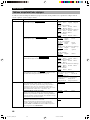
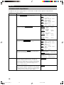
PREPARATION
PREPARATION STEPS ................................................... 10
SPEAKER SETUP ............................................................. 11
Speaker placement ........................................................... 11
Installing the speakers ..................................................... 12
CONNECTIONS ................................................................ 14
Connecting TV and audio/video components ................. 14
Connecting the antennas .................................................. 16
Connecting the speakers .................................................. 17
Connecting to an external amplifier ................................ 19
Connecting the AC power cord ........................................ 19
Turning on the power ....................................................... 19
ADJUSTING SPEAKER OUTPUT LEVELS ................ 20
Using the test tone ........................................................... 20
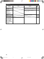
USING BASIC FUNCTIONS
BASIC PLAYBACK .......................................................... 21
Basic operations ............................................................... 21
Selecting a sound field program ...................................... 23
RECORDING .................................................................... 28
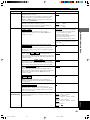
PLAYING A DISC
DISC INFORMATION ..................................................... 29
Types of disc that this unit can play ................................ 29
Region management information .................................... 29
Notes about handling discs .............................................. 29
MP3 playback .................................................................. 30
REMOTE CONTROL (DVD MODE) ............................. 31
PLAYING A DISC ............................................................. 32
Basic operation ................................................................ 32
ON-SCREEN MENU ......................................................... 34
Operating menu bar ......................................................... 34
Icons for disc menu ......................................................... 35
Icons for player menu ...................................................... 36
USING MULTIPLE FUNCTIONS .................................. 38
Using a disc’s menu ......................................................... 38
Enhancing video quality
[U.S.A. and Canada models only] ................................... 38
DVD-Audio features ........................................................ 39
Enhancing audio quality (DISC DIRECT) ...................... 40
Switching audio tracks, subtitles and angles ................... 41
All group play .................................................................. 42
Programmed play ............................................................. 42
Random play .................................................................... 43
Bookmarks ....................................................................... 44
Repeat play ...................................................................... 45
Repeat A-B ...................................................................... 46
SETUP MENU ................................................................... 47
Operating the setup menu ................................................ 47
Summary of settings ........................................................ 48
Ratings ............................................................................. 51
PCM down conversion ..................................................... 51
Speaker settings ............................................................... 52
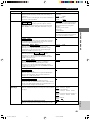
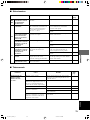
TUNING
TUNING ............................................................................. 54
Automatic and manual tuning ......................................... 54
Presetting stations ............................................................ 55
Tuning in to a preset station ............................................. 56
Exchanging preset stations .............................................. 56
RECEIVING RDS STATIONS ......................................... 57
Description of RDS data .................................................. 57
Changing the RDS mode ................................................. 58
PTY SEEK function ........................................................ 58
REMOTE CONTROL FEATURES
OPERATING OTHER COMPONENTS USING THE
REMOTE CONTROL ....................................................... 59
Setting the manufacturer code ......................................... 59
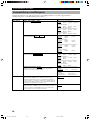
ADJUSTMENTS
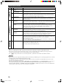
SET MENU ......................................................................... 61
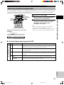
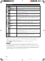
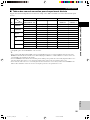
List of SET MENU items ................................................ 61
Adjusting the items on the SET MENU .......................... 61
1 SPEAKER SET (speaker mode settings) .................... 62
2 LFE LEVEL ................................................................ 63
3 SP DLY TIME (speaker delay time) ........................... 64
4 D. RANGE (dynamic range) ....................................... 64
5 L/R BALANCE (balance of the front left and right
speakers) ...................................................................... 64
6 HP TONE CTRL (headphone tone control) ................ 64
7 I/O ASSIGN (input assignment) ................................. 65
8 INPUT MODE (initial input mode) ............................ 65
9 SP/PRE OUT (output source settings) ......................... 65
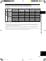
ADJUSTING THE LEVEL OF THE EFFECT
SPEAKERS ........................................................................ 66
CHANGING THE PARAMETER SETTINGS FOR DSP
PROGRAMS ...................................................................... 67
Adjusting the delay time .................................................. 67
Adjusting the parameter settings for PRO LOGIC II
Music ............................................................................... 68
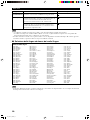
APPENDIX
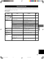
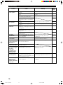
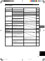
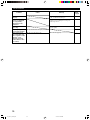
TROUBLESHOOTING .................................................... 69
GLOSSARY ....................................................................... 74
SPECIFICATIONS ............................................................ 77
103_S100_01-09_EN 02.3.22, 4:24 PM1

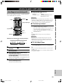
2
FEATURES
The DVX-S100 is the Home Theater Sound System that delivers a powerful and realistic sound experience like that
found in a movie theater just by combining the unit with the TV.
The newest DSP programs will enhance the power and realism of various sources, from movies to concerts, and
sporting events. Also, the Silent Cinema program allows you to enjoy the sound field even through the headphones.
Since the DVX-S100 consists of a DVD Audio/Video receiver, a center speaker, front speakers, rear speakers and a
subwoofer, you can enjoy stronger bass and surround effects as well as a good balance throughout the speakers.
Moreover, the One-touch connection of the speaker connectors designed exclusively for this unit allows you to easily
connect the speakers.
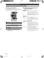
◆ Built-in 5-channel power amplifier
◆ DVD-AUDIO/VIDEO, CD, VCD, MP3, CD-R/
RW playback
◆ Dolby Pro Logic/Dolby Pro Logic II decoder
◆ Dolby Digital/Dolby Digital + Matrix 6.1
decoder
◆ DTS/DTS + Matrix 6.1 decoder
◆ Sophisticated FM/AM tuner
◆ CINEMA DSP: Combination of YAMAHA DSP
technology and Dolby Pro Logic, Dolby Digital
or DTS
◆ Virtual CINEMA DSP
◆ SILENT CINEMA DSP
◆ Easy connection of the center speaker, front
speakers and rear speakers using special speaker
connectors designed exclusively for this unit
◆ Multi-function remote control which can also be
used for other audio/video components of certain
manufacturers
■ About this manual
• y indicates a tip for your operation.
• Some operations can be performed by using the buttons
on either the main unit or the remote control. In this
case, the operations performed by using the remote
control are described in this manual.
• This manual is printed prior to production. Design and
specifications are subject to change in part for the
reason of the improvement in operativity ability, and
others. In this case, the product has priority.
• Some of the illustrations and names of the package
contents etc written in this manual may differ from the
actual products and the names written on the package
etc.
Manufactured under license from Dolby Laboratories.
“Dolby”, “Pro Logic”, and the double-D symbol are
trademarks of Dolby Laboratories.
“DTS” and “DTS Digital Surround” are registered
trademarks of Digital Theater Systems, Inc.
(U.S.A. and Canada models)
“DCDi” is a trademark of Faroudja, a division of Sage
Inc.
This product incorporates copyright protection
technology that is protected by method claims of certain
U.S. patents and other intellectual property rights owned
by Macrovision Corporation and other rights owners. Use
of this copyright protection technology must be
authorized by Macrovision Corporation, and is intended
for home and other limited viewing uses only unless
otherwise authorized by Macrovision Corporation.
Reverse engineering or disassembly is prohibited.
103_S100_01-09_EN 02.3.22, 4:24 PM2

3
INTRODUCTION
English
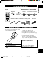
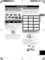
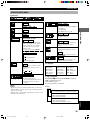
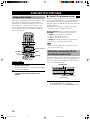
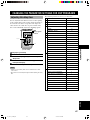
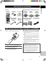
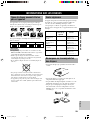
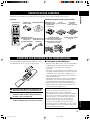
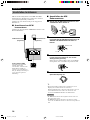
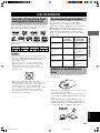
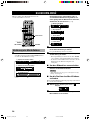
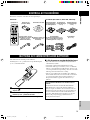
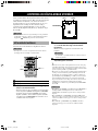
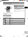
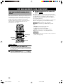
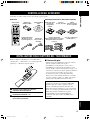
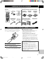
CHECKING THE ACCESSORIES
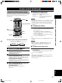
Check your package to make sure it contains the following items.
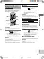
DVR-S100
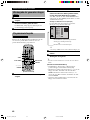
Remote control
TV
CH
INPUT
TUNER
MUTE CD–R
VCR
VIDEO 2
VIDEO 1
MD
AV
SLEEP
POWER
TV MODE
POWER
VOL
REC
AUDIO
SUBTITLE
SHIFT
CODE SET
1
HALL
2
JAZZ
SETUP
3
ROCK
ANGLE
4
ENTERTAINMENT
MARKER
5
SPORTS
6
MONO MOVIE
PLAY MODE
7
MOVIE 1
REPEAT
8
MOVIE 2
A–B
DVD
CD
AMP
9
/DTS
TOP MENU
LEVEL
FREQ/
RDS
MENU
SET MENU
TEST
ON SCREEN
B. BOOST
RETURN
PTY SEEK
MODE START
0
SELECT
>
–
10
MATRIX 6.1
GROUP
CANCEL
STEREO
PAGE
MUTE
VOL
ABCDE
ENTER
PRESET
CH
PRESET
CH
Batteries (x2)
(AA, R06, UM-3)
AM loop antenna
Indoor FM antenna
(U.S.A., Canada and
General models)
(Europe, U.K. and
Australia models)
NX-SW100 (NX-S100S x4, NX-S100C, SW-S100)
Fasteners (4 sets)
for the center
speaker
Pads
(2 sets: 16 pieces)
Speaker cables
(for the rear speakers: 15m (x2),
for the front/center speaker:
5m (x3))
System connector
cable (5m x 1)
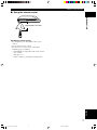
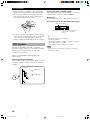
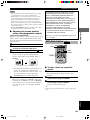
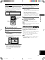
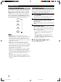
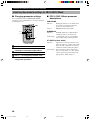
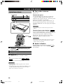
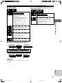
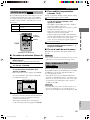
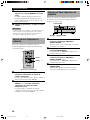
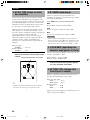
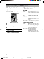
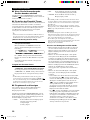
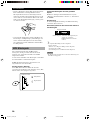
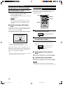
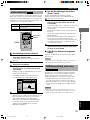
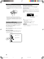
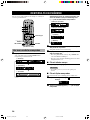
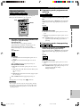
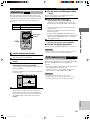
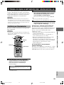
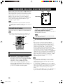
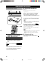
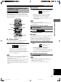
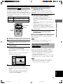
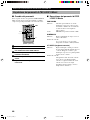
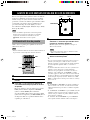
INSTALLING BATTERIES IN THE REMOTE CONTROL
Insert the batteries in the correct direction by aligning the
+ and – marks on the batteries with the polarity markings
(+ and –) inside the battery compartment.
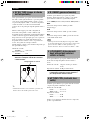
1 Press the part and slide off the battery
compartment cover.
2 Insert the two batteries (AA, R06, UM-3 type)
with + and – oriented properly.
3 Slide the cover back on so that it snaps into
place.
1
3
2
■ Notes on batteries
• Change all of the batteries if you notice a decrease in
the operating range of the remote control.
• Do not use old batteries together with new ones.
• Do not use different types of batteries (such as alkaline
and manganese batteries) together. Read the packaging
carefully as these different types of batteries may have
the same shape and color.
• If the batteries have leaked, dispose of them
immediately. Avoid touching the leaked material or
letting it come into contact with clothing, etc. Clean the
battery compartment thoroughly before installing new
batteries.
Preserving the manufacturer code
Replace batteries early before they become unusable.
The manufacturer code set by the user will be
preserved for about two minutes when batteries run
out or when they are removed. Note that the
manufacturer code setting may be lost if more than
two minutes elapses. Also, if you press any button on
the remote control accidentally while replacing
batteries, the manufacturer code will be lost.
Non-skid pads
(2 sets: 16 pieces)
103_S100_01-09_EN 02.3.22, 4:24 PM3

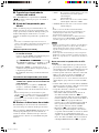
4
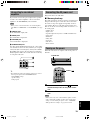
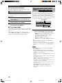
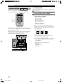
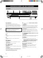
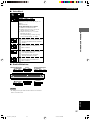
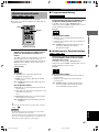
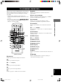
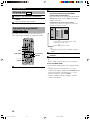
CONTROLS AND FUNCTIONS
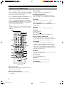
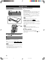
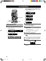
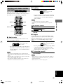
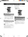
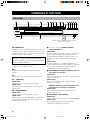
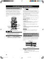
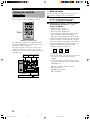
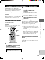
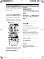
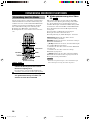
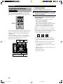
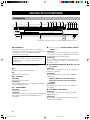
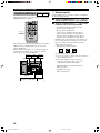
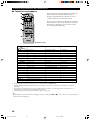
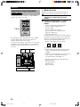
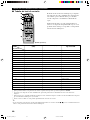
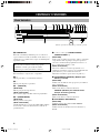
Front panel
STANDBY/ON
A/B/C/D/E
PRESET/BAND PRESET/TUNING MEMORY
PROGRESSIVE
AUTO/MAN’L
DISC DIRECT
SILENT
12 3456890qwer
y
t
7
u
MEMORY
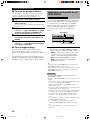
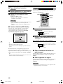
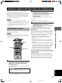
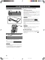
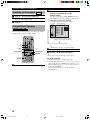
1 STANDBY/ON
Turns this unit on, or set it to the standby mode. When
you turn this unit on, you will hear a click and there will
be a 4 to 5-second delay before this unit can reproduce
sound.
Standby mode
In this mode, this unit will consume a small amount of
power in order to receive infrared-signals from the
remote control.
2 Disc tray
The disc you play is loaded on this tray.
3 v
Press to open and close the disc tray.
4 w
Press to start playback.
5 a (A/B/C/D/E)
(DVD mode)
Press to stop playback.
(Tuner mode)
Selects preset station groups A to E.
6 d (PRESET/BAND)
(DVD mode)
Press to pause.
(Tuner mode)
Switches the reception band between FM and AM and
also the mode between the tuning mode and the preset
mode.
7 t/e, r/y (d PRESET/TUNING /
PRESET/TUNING u)
(DVD mode)
Each time these buttons are pressed, the disc begins
playing from the beginning of the track you select. When
you keep pressing the buttons, the disc searches forward
or backward.
(Tuner mode)
Selects preset station numbers 1 to 8 when the colon (:)
appears in the front panel display.
Selects the tuning frequency when the colon (:) does not
appear.
8 PROGRESSIVE (MEMORY) (U.S.A. and
Canada models)
(DVD mode)
Switches between progressive video output and interlace
video output.
(Tuner mode)
Stores the current station in the memory.
MEMORY (U.K., Europe, Australia and
General models)
(Tuner mode)
Stores the current station in the memory.
9 DISC DIRECT (AUTO/MAN’L)
(DVD mode)
Changes the modes of DISC DIRECT function.
(Tuner mode)
Switches the tuning mode between automatic and manual.
(U.K., Europe, Australia and General models)
103_S100_01-09_EN 02.3.22, 4:24 PM4

5
CONTROLS AND FUNCTIONS
INTRODUCTION
English
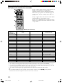
0 INPUT H/G
Selects the input source you want to listen to or watch.
q INPUT MODE
Sets the priority for the types of input signals (AUTO,
DTS, ANALOG) to receive when one component is
connected to two or more input jacks.
w DSP H/G
Selects the DSP program.
e STEREO
Switches between normal stereo and DSP effect
reproduction. When STEREO is selected, 2-channel
signals are directed to the front left and right speakers
without effect sounds.
r VOLUME +/–
Controls the output level of all audio channels.
This does not affect the recording (Rec) level.
t Remote control sensor
Receives signals from the remote control.
y Front panel display
Shows information about the operational status of this
unit.
u
SILENT
Allows you enjoy DSP effect for private listening with
headphones. When you connect headphones, no signals
are output to the speakers.
103_S100_01-09_EN 02.3.22, 4:24 PM5

6
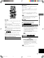
CONTROLS AND FUNCTIONS
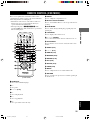
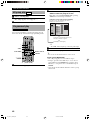
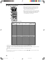
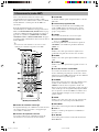
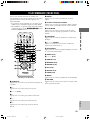
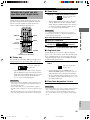
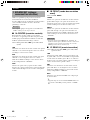
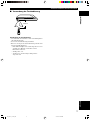
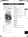
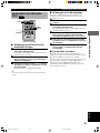
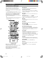
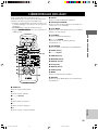
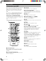
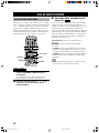
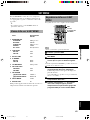
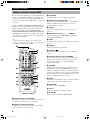
Remote control (AMP mode)
This section explains the function of each button on the
remote control when you operate this unit as an amplifier,
not as a tuner or a DVD player. Make sure that the AMP
mode is selected before starting operation.
Refer to “REMOTE CONTROL (DVD MODE)” on page
31 for the details about the functions of the remote
control when you control this unit in the DVD mode.
Also, refer to “OPERATING OTHER COMPONENTS
USING THE REMOTE CONTROL” on pages 59 and 60
for the details about its functions when controlling other
components connected to this unit.
y
• The buttons on the remote control whose names are written in
purple are operation buttons when you operate this unit in the
AMP mode.
TV
CH
INPUT
TUNER
MUTE CD–R
VCR
VIDEO 2
VIDEO 1
MD
AV
SLEEP
POWER
TV MODE
POWER
VOL
REC
AUDIO
SUBTITLE
SHIFT
CODE SET
1
HALL
2
JAZZ
SETUP
3
ROCK
ANGLE
4
ENTERTAINMENT
MARKER
5
SPORTS
6
MONO MOVIE
PLAY MODE
7
MOVIE 1
REPEAT
8
MOVIE 2
A–B
DVD
CD
AMP
9
/DTS
TOP MENU
LEVEL
MENU
SET MENU
TEST
ON SCREEN
B. BOOST
RETURN
0
SELECT
>
–
10
MATRIX 6.1
GROUP
CANCEL
STEREO
PAGE
MUTE
VOL
ABCDE
ENTER
PRESET
CH
PRESET
CH
1
3
4
5
6
7
t
r
e
w
q
0
9
8
2
AMP
(U.S.A. model)
1 Infrared window
Outputs infrared control signals. Aim this window at the
component you want to operate.
2 Basic operation buttons
Used to operate the components selected with input
selector buttons.
3 CODE SET
Used when setting up the manufacturer code.
4 DSP program buttons
Select DSP programs for the AMP position. Press a
button repeatedly to select a DSP program within that
group.
5 LEVEL
Selects the effect speaker channel to be adjusted.
6 Cursor buttons (j, i, u, d)/ENTER
Select SET MENU items and change the settings on the
SETUP menu etc.
7 TEST
Outputs the test tone to adjust the speaker levels.
8 SLEEP
Sets the sleep timer.
9 POWER (
)
Turns this unit on, or set it to the standby mode.
0 Input selector buttons/AMP
Select the input source and set the remote control to
operate the selected source component. Sets the remote
control to the AMP mode for controlling this unit.
q STEREO
Switches between normal stereo and DSP effect
reproduction. When STEREO is selected, 2-channel
signals are directed to the front left and right speakers
without effect sounds and all Dolby Digital and DTS
signals (except the LFE channel) are mixed down to the
front left and right speakers.
w MUTE
Mutes the sound. Press again to restore the audio output
to the previous volume level.
e SET MENU
Selects the SET MENU mode.
r VOL +/–
Increases or decreases the volume level.
t B. BOOST
Turns BASS BOOST function on or off.
103_S100_01-09_EN 02.3.22, 4:24 PM6

7
CONTROLS AND FUNCTIONS
INTRODUCTION
English
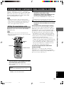
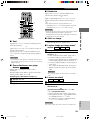
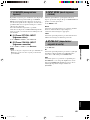
■ Using the remote control
30° 30°
Approximately 6 m (20 feet)
Handling the remote control
• Do not spill water or other liquids on the remote
control.
• Do not drop the remote control.
• Do not leave or store the remote control in the
following types of conditions:
– high humidity or temperature such as near a heater,
stove or bath;
– dusty places; or
– in places subject to extremely low temperatures.
103_S100_01-09_EN 02.3.22, 4:24 PM7

8
CONTROLS AND FUNCTIONS
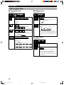
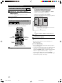
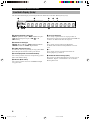
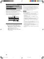
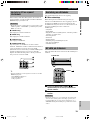
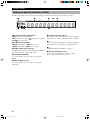
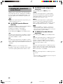
Front panel display (left)
This front panel display mainly displays the information related to the playback of discs.
PGM RND
GROUP TITLE TRACK CHAP D.MIX P.PCM MLT.CH
AB
–
DVD V CD
VIDEO
AUDIO
888888888888
1
2345
7
68 9
1 Play mode indicators
PGM: Programmed play / RND: Random play /
: Repeat play / A-B : Repeat A-B
2 Mode type indicators
GROUP: Group mode / TITLE: Title mode /
TRACK: Track mode / CHAP: Chapter mode
3 D.MIX (Down Mix)
Lights up when the currently playing multi-channel audio
track is mixed down into 2-channel.
4 P.PCM (Packed PCM)
Lights up while a P.PCM signal is input.
5 MLT.CH (Multi Channel)
Lights up while a multi-channel signal is output.
6 Disc type indicators
Indicates the type of disc. For example, DVD and AUDIO
lights up when playing a DVD-Audio disc.
7 w
Lights up during playback. Blinks while resume function
is working.
8 d
Lights up while playback is paused.
9 Multi-information display (left)
Shows various information such as title, chapter or track
number, elapsed playing time etc.
103_S100_01-09_EN 02.3.22, 4:24 PM8

9
CONTROLS AND FUNCTIONS
INTRODUCTION
English
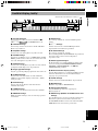
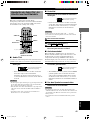
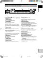
Front panel display (right)
88888888888888
MATRIX
VIRTUAL
SILENT
MOVIE THTR DTS
DOLBY DIGITAL PRO LOGIC
12
ENTERTAINMENT
DVD/CD VIDEO 1VIDEO 2 VCR
MD/CD–R TUNER
STEREO
AUTO
TUNED
PS PTY RT CT
PTY HOLD
MEMORY
SLEEP
MUTE
dB
ms
SP
PRE
B. BOOST
DIGITAL
PRO LOGIC
/
DSP
PCM
L
LFE
C R
RL RC RR
12345
6
7890
o
iuytewq
r
(U.K. and Europe models only)
1 Decoder indicators
Lights up when the t, g,
PRO LOGIC
/
or
MATRIX are activated.
2 VIRTUAL indicator
Lights up in the virtual cinema DSP mode.
3 Headphones indicator
Lights up when headphones are connected.
4 SP/PRE indicator
The indicator of the item selected in “9 SP/PRE OUT” on
the SET MENU lights up. (But it does not light up when
headphones are connected.)
5 SILENT indicator
Lights up when headphones are connected while the
digital sound field processor is on.
6 Input source indicator
Shows the current input source with a cursor.
7 STEREO indicator
Lights up when this unit is receiving a strong signal for an
FM stereo broadcast while the “AUTO” indicator is lit.
8 AUTO indicator
Shows that this unit is in the automatic tuning mode.
9 TUNED indicator
Lights up when this unit is tuned to a station.
0 MEMORY indicator
Flashes to show a station can be stored.
q DSP indicator
Lights up when you select DSP programs.
w v indicator
Lights up when this unit is reproducing PCM (pulse code
modulation) digital audio signals.
e B. BOOST indicator
Lights up when BASS BOOST is ON. (But it does not
light up when headphones are connected.)
r DSP program indicators
The name of the selected DSP program lights up when
the ENTERTAINMENT, MOVIE THEATER 1, MOVIE
THEATER 2 or V/DTS SURROUND DSP program is
selected.
t Multi-information display (right)
Shows the current DSP program name and other
information when adjusting or changing settings.
y SLEEP indicator
Lights up while the sleep timer is on.
u MUTE indicator
Flashes while the MUTE function is on.
i Input channel indicator
Indicates the channel components of input signals being
received.
o RDS indicator (U.K. and Europe models)
The name(s) of the RDS data offered by the currently
received RDS station light(s) up.
PTY HOLD indicator lights up while searching for
stations in the PTY SEEK mode.
103_S100_01-09_EN 02.3.22, 4:24 PM9

10
PREPARATION STEPS
In order to enjoy sound and video images with this sound
system, follow the procedures as described below. See
each page for details.
Installing batteries in the remote control (P.3)
Speaker setup (P.11)
• Speaker placement (P.11)
• Installing the speakers (P.12)
Connections (P.14 – 19)
• Connecting TV and audio/video components (P.14)
• Connecting the antennas (P.16)
• Connecting the speakers (P.17)
• Connecting the AC power cord (P.19)
• Turning on the power (P.19)
Adjusting speaker output levels (P.20)
Before connecting components
• Do not connect this unit or other components to the
mains power until all connections between the
components have been completed.
• Be sure all connections are made correctly, that is to
say, L (left) to L, R (right) to R, “+” to “+” and “–” to
“–”. Some components require different connection
methods and have different jack names. Refer to the
operation instructions for each component to be
connected to this unit.
• Insert the plugs properly. The speakers may not output
any sound or may output noise if they are not inserted
properly.
• The name of jack corresponds to input selector.
• The VOLTAGE SELECTOR on the rear panel of this
unit must be set for your local main voltage BEFORE
plugging into the AC main supply. Voltages are
220/240 V AC, 50 Hz. (General model)
After connecting components
• Check them again to make sure they are correct.
VOLTAGE SELECTOR
240V 220V
VOLTAGE SELECTOR
(General model)
104_S100_10-20_EN 02.3.22, 4:24 PM10

11
PREPARATION
English
SPEAKER SETUP
This unit has been designed to provide the best sound-
field quality with a 5-speaker system, using front left and
right speakers, rear left and right speakers and a center
speaker.
The front speakers are used for the main source sound
plus effect sounds. The rear speakers are used for effect
and surround sounds. The center speaker is for the center
sounds (dialog, vocals, etc.).
Notes
• If you do not use any of effect speakers (rear and/or center),
change the settings of SPEAKER SET items at the SET MENU
(p.62) to designate the signals to other terminals you connect
speakers to.
• If you use speakers (with different tonal qualities) instead of
the included speakers, the tone of a moving human voice and
other types of sound may not shift smoothly. We recommend
that you use speakers from the same manufacturer or speakers
with the same tonal quality.
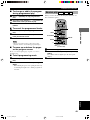
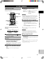
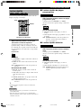
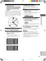
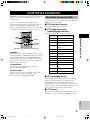
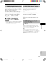
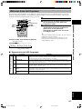
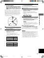
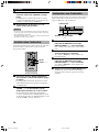
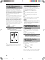
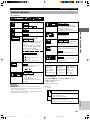
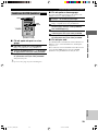
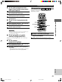
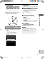
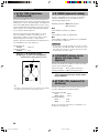
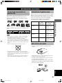
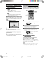
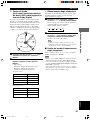
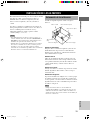
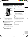
Speaker placement
Refer to the following diagram when you place the
speakers.
Front speakers
Place the front left and right speakers an equal distance
from the ideal listening position. The distance between
each speaker and each side of the video monitor should
also be the same.
Center speaker
Align the front face of the center speaker with the front
face of your video monitor. Place the speaker as close to
the monitor as possible (such as directly over or under the
monitor) and centrally between the front speakers.
Rear speakers
Place these speakers behind your listening position,
facing slightly inwards, nearly 1.8 m (6 feet) above the
floor.
Subwoofer
The position of the subwoofer is not so critical, because
low bass sounds are not highly directional. But it is better
to place the subwoofer near the front speakers. Turn it
slightly toward the center of the room to reduce wall
reflections.
Note
• Although the speaker system in this unit is magnetically
shielded, it may still affect the color on the television monitor
when using this unit near the television. Adjust the relative
positions of this unit and the television if this happens.
Center speaker Front speaker (R)
Rear speaker (R)
Front speaker (L)
1.8 m (6 feet)
Subwoofer
Rear speaker (L)
104_S100_10-20_EN 02.3.22, 4:24 PM11

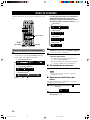
12
SPEAKER SETUP
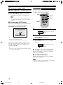
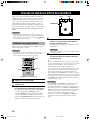
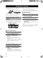
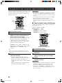
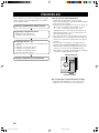
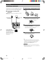
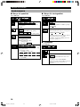
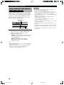
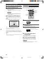
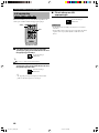
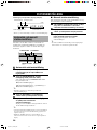
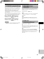
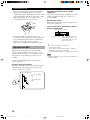
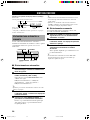
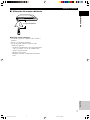
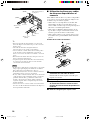
Installing the speakers
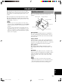
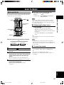
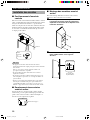
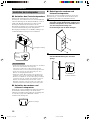
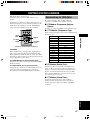
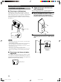
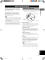
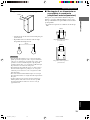
■ Placing the center speaker
Place the speaker on TV whose top is flat or on the floor
under the TV or inside the TV rack so that it is stabilized.
When placing the speaker on top of the TV, to prevent the
speaker from falling down, put the provided fasteners at
four points on the bottom of the speaker and the top of the
TV.
Cautions
• Do not place the speaker on top of the TV whose area is
smaller than the bottom area of the speaker. If placed, the
speaker may drop out causing an injury to you.
• Do not place the speaker on top of the TV with an inclination.
• Do not touch the adhesive surface after peeling off the seal as
this will weaken its adhesive strength.
• Thoroughly wipe clean the surface where the fastener is to be
applied. Note that adhesive strength is weakened if the surface
is dirty, oily or wet and that this may cause the center speaker
to drop.
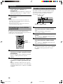
■ Placing the front and rear
speakers
When placing the front and rear speakers on a flat
surface, attach the included non-skid pads to the corners
on the bottom of the speakers as shown below. This
prevents the speakers from sliding around.
Peel off the
seal
Fastener
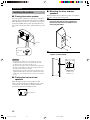
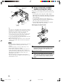
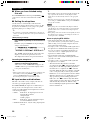
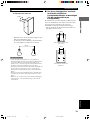
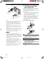
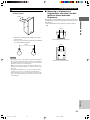
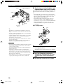
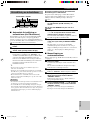
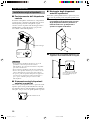
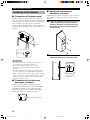
■ Mounting the front and rear
speakers
When mounting the front and rear speakers on a wall, use
the holes on the speakers’ back panels.
1 Put the provided pads at the four corners on
the rear of the front and rear speakers to
prevent the front and rear speakers from
moving by vibrations.
2 Fasten screws into a firm wall or wall
support as shown below.
Diam. 3.5 to 4 mm
Min.
20 mm
6 mm
Tapping screw
(Available at the
hardware store)
Non-skid pads
104_S100_10-20_EN 02.3.22, 4:24 PM12

13
SPEAKER SETUP
PREPARATION
English
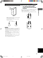
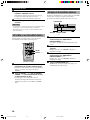
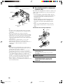
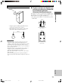
3 Hang the holes on the protruding screws.
• Make sure that the screws are securely caught by
the narrow parts of the holes.
• You can use the lower holes on the rear of the
front/rear speakers.
Cautions
• Each speaker weighs 1.1 kg (2 lbs. 6 oz.). Do not mount them
on thin plywood or a wall with soft surface material. If
mounted, the screws may come out of the flimsy surface and
the speakers may fall. This damages the speakers or causes
personal injury.
• Do not install the speakers to a wall with nails, adhesives, or
any other unstable hardware. Long-term use and vibrations
may cause them to fall.
• To avoid accidents resulting from tripping over loose speaker
cables, fix them to the wall.
• Select a proper position on the wall to mount the speaker so
that no one will injure his/her head or face.
60 mm
60 mm
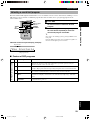
■ If you want to mount a speaker
on a commercially available
speaker stand (for the front/rear
speakers)
The screw holes (at an interval of 60 mm) on the bottom
and the rear of the speaker can be used to mount the
speaker on a speaker stand.
* Those screw holes can be used with M4 screws only.
60 mm
Front/rear speaker
(bottom)
60 mm
Front/rear speaker
(rear)
104_S100_10-20_EN 02.3.22, 4:24 PM13

14
CONNECTIONS
Connecting TV and audio/video
components
■ Types of video jacks
1 COMPONENT VIDEO jacks (U.S.A., Canada,
Australia and General models)
Transmit color difference (PB/CB, PR/CR) and luminance
separately and provide the best quality picture.
2 VIDEO jack
Conventional composite video signal.
3 S VIDEO jack
Transmits color and luminance separately and achieves
high-quality color reproduction.
Notes
• Each type of video jack works independently. Signals input
through the composite video and S video jacks are only output
through the corresponding composite video and S video jacks.
• When you connect this unit to a video monitor, a video
component and a recording component, connect the same types
of jack, for example, the video jack on this unit to the video
jack on the video component.
• The description of the component video jacks may differ
depending on the component (e.g. Y, CB, CR/Y, PB, PR/Y, B-Y,
R-Y etc.). When using these jacks, refer also to the operation
instructions for the component being connected.
• Do not connect this unit to a video monitor through a video
cassette recorder. If you do so, the picture may not be played
back properly due to the copyright protection technology
incorporated in this unit.
• When progressive output (p.38) is selected in the DVD mode,
video signals are only output from the component video jacks.
321
PR PB Y
■ Types of audio jacks
1 COAXIAL jack
Connects a coaxial pin cable and provides the better
quality sound than analog audio jacks.
2 OPTICAL jack
Connects an optical fiber cable and provides the better
quality sound than analog audio jacks.
3 Analog audio jacks
Connect an audio pin cable.
y
• 1 and 2 are digital jacks.
• You can use the digital jacks to input PCM, Dolby Digital and
DTS bitstreams.
• All digital input jacks are acceptable for 96-kHz sampling
digital signals.
Notes
• DIGITAL OUTPUT jack and analog OUT (Rec) jacks are
independent. Only digital signals are output from DIGITAL
OUTPUT jack and analog signals from OUT (Rec) jacks.
• The OPTICAL jacks on this unit conform to the EIA standard.
If you use an optical cable that does not conform to this
standard, this unit may not function properly.
• Once you have connected a recording component to this unit,
keep its power turned on while using this unit. If the power is
off, this unit may distort the sound from other components.
Anti-dust cap
Remove the cap covering the OPTICAL jacks when
connecting an optical cable. Safely store the cap and
always re-insert it in the terminal when the terminal is not
in use. (This cap prevents the entrance of dust.)
1 23
L
R
Anti-dust cap
104_S100_10-20_EN 02.3.22, 4:24 PM14

15
CONNECTIONS
PREPARATION
English
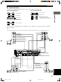
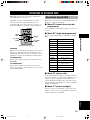
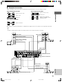
The connection example shown below is just an example. Connect in accordance with the components you have.
y
• The solid lines indicate the output from this unit and the dotted lines indicate the input to this unit.
■ The connection example
Use a commercially available cable specified for connecting each type of jacks.
For Audio component
Audio pin cable
Coaxial cable
Optical cable
For A/V component
Audio/Video cable
For Video Component
Video pin cable
S Video cable
Component video cable
(U.S.A., Canada, Australia and General
models)
FM ANT
75ΩUNBAL.
GND – AM ANT
P
R
P
B
Y
L
IN
VIDEO 1 VIDEO 2
VIDEO
VCR
IN IN
IN IN IN
OUT OUT
IN IN IN INOUT OUT
OUT OUT
S VIDEO
MONITOR
MD/CD-R FRONT CENTER
SYSTEM
MONITOR
6CH PREOUT
VIDEO 1 VIDEO 2 VCR
REAR
SUBWOOFER
R
MD/CD-R
COMPONENT VIDEO OUT
OPTICAL
OUT
CONNECTOR
MARK
TO SW-S100
[
B
]
[
A
]
COAXIAL
IN
OPTICAL
IN
MD/CD-R VIDEO 1
DIGITAL
ANALOG
S VIDEO
INPUT
VIDEO
AUDIO
L
R
S VIDEO
OUTPUT
VIDEO
AUDIO
L
R
S VIDEO
INPUT
VIDEO
COMPONENT
VIDEO
S VIDEO
OUTPUT
OPTICAL
AUDIO
L
VIDEO
R
INPUT
OPTICAL
AUDIO
L
R
OUTPUT
COAXIAL
AUDIO
L
R
PB/CB
PR/CR
Y
S Video cable
Video pin cable
Component video cable
(U.S.A., Canada, Australia and General
models)
Video monitor
S Video cable
Audio/Video
cable
VCR
S Video cable
Audio/Video cable
(U.S.A. model)
Coaxial cable
Audio pin cable
Optical cable
CD recorder or MD recorder
Audio pin cable
S Video cable
Optical cable
Audio/Video cable
TV/digital TV/cable TV
104_S100_10-20_EN 02.3.27, 5:51 PM15

16
CONNECTIONS
Connecting the antennas
Both AM and FM indoor antennas are included with this
unit. In general, these antennas should provide sufficient
signal strength.
Connect each antenna correctly to the designated
terminals.
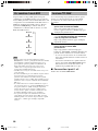
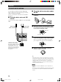
■ Connecting indoor FM antenna
Connect the included indoor FM antenna to the FM ANT
terminal.
75ΩUNBAL.
FM ANT GND – AM ANT
Ground (GND terminal)
For maximum safety and
minimum interference, connect
the antenna GND terminal to a
good earth ground. A good earth
ground is a metal stake driven into
moist earth.
Indoor FM antenna
(included)
AM loop antenna
(included)
■ Connecting the AM loop antenna
1 Set up the AM loop antenna, then connect it.
2 Press and hold the tab to insert the AM loop
antenna lead wires into the AM ANT and
GND terminals.
3 Release the tab. (The tab will return to its
original position when you release your
finger.)
Once connected, pull the wires gently to check that
they are connected securely.
4 Orient the AM loop antenna for the best
reception.
y
• A properly installed outdoor antenna provides clearer reception
than an indoor one. If you experience poor reception quality, an
outdoor antenna may improve the quality. Consult the nearest
authorized YAMAHA dealer or service center about the
outdoor antennas.
Notes
• The AM loop antenna should be placed away from this unit.
• The AM loop antenna should always be connected, even if an
outdoor AM antenna is connected to this unit.
Bare wire
Tab
104_S100_10-20_EN 02.3.22, 4:24 PM16

17
CONNECTIONS
PREPARATION
English
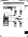
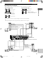
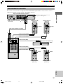
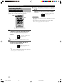
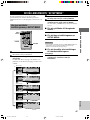
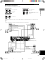
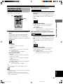
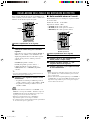
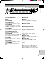
Connecting the speakers
Connect the included speakers to the DVD AUDIO/VIDEO receiver (DVR-S100) using the included speaker cables and
system connector cables as shown below.
L
IN
VIDEO 1 VIDEO 2
VIDEO
VCR
IN IN
IN IN IN
OUT OUT
IN IN IN INOUT OUT
OUT OUT
S VIDEO
MONITOR
ANALOG
MD/CD-R FRONT CENTER
SYSTEM
MONITOR
6CH PREOUT
VIDEO 1 VIDEO 2 VCR
REAR
SUBWOOFER
[
B
]
[
A
]
R
COAXIAL
IN
MD/CD-R
FM ANT
75ΩUNBAL.
GND – AM ANT
MD/CD-RVIDEO 1
DIGITAL
OPTICAL
IN
OPTICAL
OUT
CONNECTOR
MARK
TO SW-S100
MARK
REAR
CENTERFRONT FRONT
(GREEN)
(WHITE)
(BLUE)
(SURROUND)
DO NOT CONNECT THIS UNIT TO
SPEAKERS OTHER THAN NX-S100C
AND NX-S100S.
(GRAY)
(RED)
R L
L
R
SYSTEM
CONNECTOR
TO DVR-S100
SPEAKERS
CENTER
REAR L
REAR R
*1
*1
FRONT R
FRONT L
DVD Audio/Video receiver (DVR-S100)
As this terminal is used for testing at the
factory, do not connect any equipment to this
terminal.
*1 Insert the plug with its
mark facing up.
System connector cable
Front speaker (R)
(NX-S100S)
Front speaker (L)
(NX-S100S)
(RED) (WHITE)
Speaker cable (RED)
Speaker cable (WHITE)
Speaker cable (GREEN)
Speaker cable (BLUE)
Speaker cable (GRAY)
Center speaker (NX-S100C)
(GREEN)
(GRAY) (BLUE)
Subwoofer (SW-S100)
Rear speaker (R)
(NX-S100S)
Rear speaker (L)
(NX-S100S)
104_S100_10-20_EN 02.3.22, 4:24 PM17

18
CONNECTIONS
y
• The connector of the included speaker cable and the terminal of
the subwoofer are classified by color. Connect the same colors.
• The label of the speaker is attached to each speaker cable.
Connect the speakers in accordance with the labels.
• Connect the color tube of the speaker cable to the plus (+) side
of each speaker. If the polarity of the speaker connections is
incorrect, the sound will be unnatural and lack bass.
• A cover is attached to the end of the speaker cable. Connect the
speakers after removing the cover.
• Make sure that the plugs of the system connector cable and the
connectors of the speaker cables are inserted correctly before
inserting them.
Notes
• Do not let the bare speaker wires touch each other or any metal
part of this unit. This could damage this unit and/or the
speakers.
• Do not insert the plug or connector forcibly. Doing so may
damage the plug, connector or terminal.
• Do not scratch, forcibly bend, or pull the system connector or
speaker cable as this may damage the cable, causing loss of
audio output, and may possibly result in a fire or electric shock.
Take particular care in making sure that the cable is not
squashed by a rack or caster.
• Before disconnecting or connecting the system connector
cable, disconnect the power supply cord of the subwoofer and
DVD audio/video receiver.
(RED)
(RED)
Color tube
(RED)
Color tube
(BLUE)
(BLUE)
Connector
(BLUE)
The back of the
Subwoofer
Connector
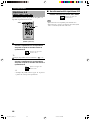
■ Using commercially available
speakers and speaker cables
You can use commercially available speaker cables and
speakers except for a subwoofer. If you use them, note the
following.
• Use the speaker whose impedance is 6Ω or higher.
When using the speaker whose impedance is lower than
6Ω, the protection circuit may start working or this unit
may be damaged.
• Use magnetically shielded speakers. If this type of
speakers still creates the interference with the monitor,
place the speakers away from the monitor.
• Use the speaker cable that is as thick as the included
cable. Too thick cables cannot be used.
Exchanging the speaker cables
1 Remove approximately 15 mm (9/16”) of
insulation from each of the speaker cables.
Twist the exposed wires of the cable together to
prevent short circuits.
2 Open the tab.
3 Pull the inserted bare wire of the speaker
cable from the connector and insert the bare
wire of the commercially available speaker
cable.
4 Return the tab to secure the wire.
2
3
1
4
15 mm
Tab
104_S100_10-20_EN 02.3.22, 4:24 PM18
Pagina se încarcă...
Pagina se încarcă...
Pagina se încarcă...
Pagina se încarcă...
Pagina se încarcă...
Pagina se încarcă...
Pagina se încarcă...
Pagina se încarcă...
Pagina se încarcă...
Pagina se încarcă...
Pagina se încarcă...
Pagina se încarcă...
Pagina se încarcă...
Pagina se încarcă...
Pagina se încarcă...
Pagina se încarcă...
Pagina se încarcă...
Pagina se încarcă...
Pagina se încarcă...
Pagina se încarcă...
Pagina se încarcă...
Pagina se încarcă...
Pagina se încarcă...
Pagina se încarcă...
Pagina se încarcă...
Pagina se încarcă...
Pagina se încarcă...
Pagina se încarcă...
Pagina se încarcă...
Pagina se încarcă...
Pagina se încarcă...
Pagina se încarcă...
Pagina se încarcă...
Pagina se încarcă...
Pagina se încarcă...
Pagina se încarcă...
Pagina se încarcă...
Pagina se încarcă...
Pagina se încarcă...
Pagina se încarcă...
Pagina se încarcă...
Pagina se încarcă...
Pagina se încarcă...
Pagina se încarcă...
Pagina se încarcă...
Pagina se încarcă...
Pagina se încarcă...
Pagina se încarcă...
Pagina se încarcă...
Pagina se încarcă...
Pagina se încarcă...
Pagina se încarcă...
Pagina se încarcă...
Pagina se încarcă...
Pagina se încarcă...
Pagina se încarcă...
Pagina se încarcă...
Pagina se încarcă...
Pagina se încarcă...
Pagina se încarcă...
Pagina se încarcă...
Pagina se încarcă...
Pagina se încarcă...
Pagina se încarcă...
Pagina se încarcă...
Pagina se încarcă...
Pagina se încarcă...
Pagina se încarcă...
Pagina se încarcă...
Pagina se încarcă...
Pagina se încarcă...
Pagina se încarcă...
Pagina se încarcă...
Pagina se încarcă...
Pagina se încarcă...
Pagina se încarcă...
Pagina se încarcă...
Pagina se încarcă...
Pagina se încarcă...
Pagina se încarcă...
Pagina se încarcă...
Pagina se încarcă...
Pagina se încarcă...
Pagina se încarcă...
Pagina se încarcă...
Pagina se încarcă...
Pagina se încarcă...
Pagina se încarcă...
Pagina se încarcă...
Pagina se încarcă...
Pagina se încarcă...
Pagina se încarcă...
Pagina se încarcă...
Pagina se încarcă...
Pagina se încarcă...
Pagina se încarcă...
Pagina se încarcă...
Pagina se încarcă...
Pagina se încarcă...
Pagina se încarcă...
Pagina se încarcă...
Pagina se încarcă...
Pagina se încarcă...
Pagina se încarcă...
Pagina se încarcă...
Pagina se încarcă...
Pagina se încarcă...
Pagina se încarcă...
Pagina se încarcă...
Pagina se încarcă...
Pagina se încarcă...
Pagina se încarcă...
Pagina se încarcă...
Pagina se încarcă...
Pagina se încarcă...
Pagina se încarcă...
Pagina se încarcă...
Pagina se încarcă...
Pagina se încarcă...
Pagina se încarcă...
Pagina se încarcă...
Pagina se încarcă...
Pagina se încarcă...
Pagina se încarcă...
Pagina se încarcă...
Pagina se încarcă...
Pagina se încarcă...
Pagina se încarcă...
Pagina se încarcă...
Pagina se încarcă...
Pagina se încarcă...
Pagina se încarcă...
Pagina se încarcă...
Pagina se încarcă...
Pagina se încarcă...
Pagina se încarcă...
Pagina se încarcă...
Pagina se încarcă...
Pagina se încarcă...
Pagina se încarcă...
Pagina se încarcă...
Pagina se încarcă...
Pagina se încarcă...
Pagina se încarcă...
Pagina se încarcă...
Pagina se încarcă...
Pagina se încarcă...
Pagina se încarcă...
Pagina se încarcă...
Pagina se încarcă...
Pagina se încarcă...
Pagina se încarcă...
Pagina se încarcă...
Pagina se încarcă...
Pagina se încarcă...
Pagina se încarcă...
Pagina se încarcă...
Pagina se încarcă...
Pagina se încarcă...
Pagina se încarcă...
Pagina se încarcă...
Pagina se încarcă...
Pagina se încarcă...
Pagina se încarcă...
Pagina se încarcă...
Pagina se încarcă...
Pagina se încarcă...
Pagina se încarcă...
Pagina se încarcă...
Pagina se încarcă...
Pagina se încarcă...
Pagina se încarcă...
Pagina se încarcă...
Pagina se încarcă...
Pagina se încarcă...
Pagina se încarcă...
Pagina se încarcă...
Pagina se încarcă...
Pagina se încarcă...
Pagina se încarcă...
Pagina se încarcă...
Pagina se încarcă...
Pagina se încarcă...
Pagina se încarcă...
Pagina se încarcă...
Pagina se încarcă...
Pagina se încarcă...
Pagina se încarcă...
Pagina se încarcă...
Pagina se încarcă...
Pagina se încarcă...
Pagina se încarcă...
Pagina se încarcă...
Pagina se încarcă...
Pagina se încarcă...
Pagina se încarcă...
Pagina se încarcă...
Pagina se încarcă...
Pagina se încarcă...
Pagina se încarcă...
Pagina se încarcă...
Pagina se încarcă...
Pagina se încarcă...
Pagina se încarcă...
Pagina se încarcă...
Pagina se încarcă...
Pagina se încarcă...
Pagina se încarcă...
Pagina se încarcă...
Pagina se încarcă...
Pagina se încarcă...
Pagina se încarcă...
Pagina se încarcă...
Pagina se încarcă...
Pagina se încarcă...
Pagina se încarcă...
Pagina se încarcă...
Pagina se încarcă...
Pagina se încarcă...
Pagina se încarcă...
Pagina se încarcă...
Pagina se încarcă...
Pagina se încarcă...
Pagina se încarcă...
Pagina se încarcă...
Pagina se încarcă...
Pagina se încarcă...
Pagina se încarcă...
Pagina se încarcă...
Pagina se încarcă...
Pagina se încarcă...
Pagina se încarcă...
Pagina se încarcă...
Pagina se încarcă...
Pagina se încarcă...
Pagina se încarcă...
Pagina se încarcă...
Pagina se încarcă...
Pagina se încarcă...
Pagina se încarcă...
Pagina se încarcă...
Pagina se încarcă...
Pagina se încarcă...
Pagina se încarcă...
Pagina se încarcă...
Pagina se încarcă...
Pagina se încarcă...
Pagina se încarcă...
Pagina se încarcă...
Pagina se încarcă...
Pagina se încarcă...
Pagina se încarcă...
Pagina se încarcă...
Pagina se încarcă...
Pagina se încarcă...
Pagina se încarcă...
Pagina se încarcă...
Pagina se încarcă...
Pagina se încarcă...
Pagina se încarcă...
Pagina se încarcă...
Pagina se încarcă...
Pagina se încarcă...
Pagina se încarcă...
Pagina se încarcă...
Pagina se încarcă...
Pagina se încarcă...
Pagina se încarcă...
Pagina se încarcă...
Pagina se încarcă...
Pagina se încarcă...
Pagina se încarcă...
Pagina se încarcă...
Pagina se încarcă...
Pagina se încarcă...
Pagina se încarcă...
Pagina se încarcă...
Pagina se încarcă...
Pagina se încarcă...
Pagina se încarcă...
Pagina se încarcă...
Pagina se încarcă...
Pagina se încarcă...
Pagina se încarcă...
Pagina se încarcă...
Pagina se încarcă...
Pagina se încarcă...
Pagina se încarcă...
Pagina se încarcă...
Pagina se încarcă...
Pagina se încarcă...
Pagina se încarcă...
Pagina se încarcă...
Pagina se încarcă...
Pagina se încarcă...
Pagina se încarcă...
Pagina se încarcă...
Pagina se încarcă...
Pagina se încarcă...
Pagina se încarcă...
Pagina se încarcă...
Pagina se încarcă...
Pagina se încarcă...
Pagina se încarcă...
Pagina se încarcă...
Pagina se încarcă...
Pagina se încarcă...
Pagina se încarcă...
Pagina se încarcă...
Pagina se încarcă...
Pagina se încarcă...
Pagina se încarcă...
Pagina se încarcă...
Pagina se încarcă...
Pagina se încarcă...
Pagina se încarcă...
Pagina se încarcă...
Pagina se încarcă...
Pagina se încarcă...
Pagina se încarcă...
Pagina se încarcă...
Pagina se încarcă...
Pagina se încarcă...
Pagina se încarcă...
Pagina se încarcă...
Pagina se încarcă...
Pagina se încarcă...
Pagina se încarcă...
Pagina se încarcă...
Pagina se încarcă...
Pagina se încarcă...
Pagina se încarcă...
Pagina se încarcă...
Pagina se încarcă...
Pagina se încarcă...
Pagina se încarcă...
Pagina se încarcă...
Pagina se încarcă...
Pagina se încarcă...
Pagina se încarcă...
Pagina se încarcă...
Pagina se încarcă...
Pagina se încarcă...
Pagina se încarcă...
Pagina se încarcă...
Pagina se încarcă...
Pagina se încarcă...
Pagina se încarcă...
Pagina se încarcă...
Pagina se încarcă...
Pagina se încarcă...
Pagina se încarcă...
Pagina se încarcă...
Pagina se încarcă...
Pagina se încarcă...
Pagina se încarcă...
Pagina se încarcă...
Pagina se încarcă...
Pagina se încarcă...
Pagina se încarcă...
Pagina se încarcă...
Pagina se încarcă...
Pagina se încarcă...
Pagina se încarcă...
Pagina se încarcă...
Pagina se încarcă...
Pagina se încarcă...
Pagina se încarcă...
Pagina se încarcă...
Pagina se încarcă...
Pagina se încarcă...
Pagina se încarcă...
Pagina se încarcă...
Pagina se încarcă...
Pagina se încarcă...
Pagina se încarcă...
Pagina se încarcă...
Pagina se încarcă...
Pagina se încarcă...
Pagina se încarcă...
Pagina se încarcă...
Pagina se încarcă...
Pagina se încarcă...
Pagina se încarcă...
Pagina se încarcă...
Pagina se încarcă...
Pagina se încarcă...
Pagina se încarcă...
Pagina se încarcă...
Pagina se încarcă...
Pagina se încarcă...
Pagina se încarcă...
Pagina se încarcă...
Pagina se încarcă...
Pagina se încarcă...
Pagina se încarcă...
Pagina se încarcă...
Pagina se încarcă...
Pagina se încarcă...
Pagina se încarcă...
Pagina se încarcă...
Pagina se încarcă...
Pagina se încarcă...
Pagina se încarcă...
Pagina se încarcă...
Pagina se încarcă...
Pagina se încarcă...
Pagina se încarcă...
Pagina se încarcă...
Pagina se încarcă...
Pagina se încarcă...
Pagina se încarcă...
Pagina se încarcă...
Pagina se încarcă...
Pagina se încarcă...
Pagina se încarcă...
Pagina se încarcă...
Pagina se încarcă...
Pagina se încarcă...
Pagina se încarcă...
Pagina se încarcă...
Pagina se încarcă...
Pagina se încarcă...
Pagina se încarcă...
Pagina se încarcă...
Pagina se încarcă...
Pagina se încarcă...
Pagina se încarcă...
Pagina se încarcă...
Pagina se încarcă...
Pagina se încarcă...
Pagina se încarcă...
Pagina se încarcă...
Pagina se încarcă...
Pagina se încarcă...
Pagina se încarcă...
Pagina se încarcă...
Pagina se încarcă...
Pagina se încarcă...
Pagina se încarcă...
Pagina se încarcă...
Pagina se încarcă...
Pagina se încarcă...
Pagina se încarcă...
Pagina se încarcă...
Pagina se încarcă...
Pagina se încarcă...
Pagina se încarcă...
Pagina se încarcă...
Pagina se încarcă...
Pagina se încarcă...
Pagina se încarcă...
Pagina se încarcă...
Pagina se încarcă...
Pagina se încarcă...
Pagina se încarcă...
Pagina se încarcă...
Pagina se încarcă...
Pagina se încarcă...
Pagina se încarcă...
Pagina se încarcă...
Pagina se încarcă...
Pagina se încarcă...
Pagina se încarcă...
Pagina se încarcă...
Pagina se încarcă...
Pagina se încarcă...
Pagina se încarcă...
Pagina se încarcă...
Pagina se încarcă...
Pagina se încarcă...
Pagina se încarcă...
Pagina se încarcă...
Pagina se încarcă...
Pagina se încarcă...
Pagina se încarcă...
Pagina se încarcă...
Pagina se încarcă...
Pagina se încarcă...
Pagina se încarcă...
Pagina se încarcă...
Pagina se încarcă...
Pagina se încarcă...
Pagina se încarcă...
Pagina se încarcă...
Pagina se încarcă...
Pagina se încarcă...
Pagina se încarcă...
Pagina se încarcă...
Pagina se încarcă...
Pagina se încarcă...
Pagina se încarcă...
Pagina se încarcă...
Pagina se încarcă...
Pagina se încarcă...
Pagina se încarcă...
Pagina se încarcă...
Pagina se încarcă...
Pagina se încarcă...
Pagina se încarcă...
Pagina se încarcă...
Pagina se încarcă...
Pagina se încarcă...
Pagina se încarcă...
Pagina se încarcă...
Pagina se încarcă...
Pagina se încarcă...
Pagina se încarcă...
Pagina se încarcă...
Pagina se încarcă...
Pagina se încarcă...
Pagina se încarcă...
Pagina se încarcă...
Pagina se încarcă...
Pagina se încarcă...
Pagina se încarcă...
Pagina se încarcă...
Pagina se încarcă...
Pagina se încarcă...
Pagina se încarcă...
Pagina se încarcă...
Pagina se încarcă...
Pagina se încarcă...
Pagina se încarcă...
Pagina se încarcă...
Pagina se încarcă...
Pagina se încarcă...
Pagina se încarcă...
Pagina se încarcă...
Pagina se încarcă...
Pagina se încarcă...
-
 1
1
-
 2
2
-
 3
3
-
 4
4
-
 5
5
-
 6
6
-
 7
7
-
 8
8
-
 9
9
-
 10
10
-
 11
11
-
 12
12
-
 13
13
-
 14
14
-
 15
15
-
 16
16
-
 17
17
-
 18
18
-
 19
19
-
 20
20
-
 21
21
-
 22
22
-
 23
23
-
 24
24
-
 25
25
-
 26
26
-
 27
27
-
 28
28
-
 29
29
-
 30
30
-
 31
31
-
 32
32
-
 33
33
-
 34
34
-
 35
35
-
 36
36
-
 37
37
-
 38
38
-
 39
39
-
 40
40
-
 41
41
-
 42
42
-
 43
43
-
 44
44
-
 45
45
-
 46
46
-
 47
47
-
 48
48
-
 49
49
-
 50
50
-
 51
51
-
 52
52
-
 53
53
-
 54
54
-
 55
55
-
 56
56
-
 57
57
-
 58
58
-
 59
59
-
 60
60
-
 61
61
-
 62
62
-
 63
63
-
 64
64
-
 65
65
-
 66
66
-
 67
67
-
 68
68
-
 69
69
-
 70
70
-
 71
71
-
 72
72
-
 73
73
-
 74
74
-
 75
75
-
 76
76
-
 77
77
-
 78
78
-
 79
79
-
 80
80
-
 81
81
-
 82
82
-
 83
83
-
 84
84
-
 85
85
-
 86
86
-
 87
87
-
 88
88
-
 89
89
-
 90
90
-
 91
91
-
 92
92
-
 93
93
-
 94
94
-
 95
95
-
 96
96
-
 97
97
-
 98
98
-
 99
99
-
 100
100
-
 101
101
-
 102
102
-
 103
103
-
 104
104
-
 105
105
-
 106
106
-
 107
107
-
 108
108
-
 109
109
-
 110
110
-
 111
111
-
 112
112
-
 113
113
-
 114
114
-
 115
115
-
 116
116
-
 117
117
-
 118
118
-
 119
119
-
 120
120
-
 121
121
-
 122
122
-
 123
123
-
 124
124
-
 125
125
-
 126
126
-
 127
127
-
 128
128
-
 129
129
-
 130
130
-
 131
131
-
 132
132
-
 133
133
-
 134
134
-
 135
135
-
 136
136
-
 137
137
-
 138
138
-
 139
139
-
 140
140
-
 141
141
-
 142
142
-
 143
143
-
 144
144
-
 145
145
-
 146
146
-
 147
147
-
 148
148
-
 149
149
-
 150
150
-
 151
151
-
 152
152
-
 153
153
-
 154
154
-
 155
155
-
 156
156
-
 157
157
-
 158
158
-
 159
159
-
 160
160
-
 161
161
-
 162
162
-
 163
163
-
 164
164
-
 165
165
-
 166
166
-
 167
167
-
 168
168
-
 169
169
-
 170
170
-
 171
171
-
 172
172
-
 173
173
-
 174
174
-
 175
175
-
 176
176
-
 177
177
-
 178
178
-
 179
179
-
 180
180
-
 181
181
-
 182
182
-
 183
183
-
 184
184
-
 185
185
-
 186
186
-
 187
187
-
 188
188
-
 189
189
-
 190
190
-
 191
191
-
 192
192
-
 193
193
-
 194
194
-
 195
195
-
 196
196
-
 197
197
-
 198
198
-
 199
199
-
 200
200
-
 201
201
-
 202
202
-
 203
203
-
 204
204
-
 205
205
-
 206
206
-
 207
207
-
 208
208
-
 209
209
-
 210
210
-
 211
211
-
 212
212
-
 213
213
-
 214
214
-
 215
215
-
 216
216
-
 217
217
-
 218
218
-
 219
219
-
 220
220
-
 221
221
-
 222
222
-
 223
223
-
 224
224
-
 225
225
-
 226
226
-
 227
227
-
 228
228
-
 229
229
-
 230
230
-
 231
231
-
 232
232
-
 233
233
-
 234
234
-
 235
235
-
 236
236
-
 237
237
-
 238
238
-
 239
239
-
 240
240
-
 241
241
-
 242
242
-
 243
243
-
 244
244
-
 245
245
-
 246
246
-
 247
247
-
 248
248
-
 249
249
-
 250
250
-
 251
251
-
 252
252
-
 253
253
-
 254
254
-
 255
255
-
 256
256
-
 257
257
-
 258
258
-
 259
259
-
 260
260
-
 261
261
-
 262
262
-
 263
263
-
 264
264
-
 265
265
-
 266
266
-
 267
267
-
 268
268
-
 269
269
-
 270
270
-
 271
271
-
 272
272
-
 273
273
-
 274
274
-
 275
275
-
 276
276
-
 277
277
-
 278
278
-
 279
279
-
 280
280
-
 281
281
-
 282
282
-
 283
283
-
 284
284
-
 285
285
-
 286
286
-
 287
287
-
 288
288
-
 289
289
-
 290
290
-
 291
291
-
 292
292
-
 293
293
-
 294
294
-
 295
295
-
 296
296
-
 297
297
-
 298
298
-
 299
299
-
 300
300
-
 301
301
-
 302
302
-
 303
303
-
 304
304
-
 305
305
-
 306
306
-
 307
307
-
 308
308
-
 309
309
-
 310
310
-
 311
311
-
 312
312
-
 313
313
-
 314
314
-
 315
315
-
 316
316
-
 317
317
-
 318
318
-
 319
319
-
 320
320
-
 321
321
-
 322
322
-
 323
323
-
 324
324
-
 325
325
-
 326
326
-
 327
327
-
 328
328
-
 329
329
-
 330
330
-
 331
331
-
 332
332
-
 333
333
-
 334
334
-
 335
335
-
 336
336
-
 337
337
-
 338
338
-
 339
339
-
 340
340
-
 341
341
-
 342
342
-
 343
343
-
 344
344
-
 345
345
-
 346
346
-
 347
347
-
 348
348
-
 349
349
-
 350
350
-
 351
351
-
 352
352
-
 353
353
-
 354
354
-
 355
355
-
 356
356
-
 357
357
-
 358
358
-
 359
359
-
 360
360
-
 361
361
-
 362
362
-
 363
363
-
 364
364
-
 365
365
-
 366
366
-
 367
367
-
 368
368
-
 369
369
-
 370
370
-
 371
371
-
 372
372
-
 373
373
-
 374
374
-
 375
375
-
 376
376
-
 377
377
-
 378
378
-
 379
379
-
 380
380
-
 381
381
-
 382
382
-
 383
383
-
 384
384
-
 385
385
-
 386
386
-
 387
387
-
 388
388
-
 389
389
-
 390
390
-
 391
391
-
 392
392
-
 393
393
-
 394
394
-
 395
395
-
 396
396
-
 397
397
-
 398
398
-
 399
399
-
 400
400
-
 401
401
-
 402
402
-
 403
403
-
 404
404
-
 405
405
-
 406
406
-
 407
407
-
 408
408
-
 409
409
-
 410
410
-
 411
411
-
 412
412
-
 413
413
-
 414
414
-
 415
415
-
 416
416
-
 417
417
-
 418
418
-
 419
419
-
 420
420
-
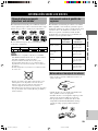 421
421
-
 422
422
-
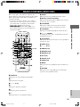 423
423
-
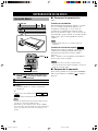 424
424
-
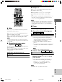 425
425
-
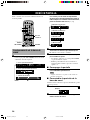 426
426
-
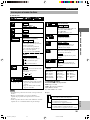 427
427
-
 428
428
-
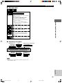 429
429
-
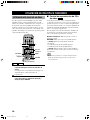 430
430
-
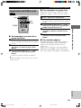 431
431
-
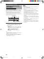 432
432
-
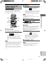 433
433
-
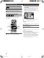 434
434
-
 435
435
-
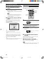 436
436
-
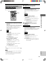 437
437
-
 438
438
-
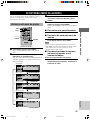 439
439
-
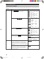 440
440
-
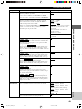 441
441
-
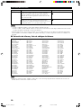 442
442
-
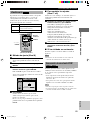 443
443
-
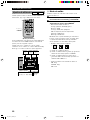 444
444
-
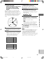 445
445
-
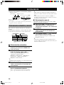 446
446
-
 447
447
-
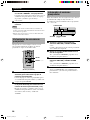 448
448
-
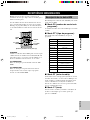 449
449
-
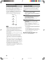 450
450
-
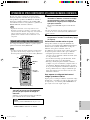 451
451
-
 452
452
-
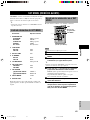 453
453
-
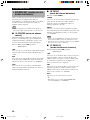 454
454
-
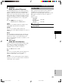 455
455
-
 456
456
-
 457
457
-
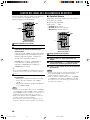 458
458
-
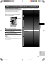 459
459
-
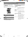 460
460
-
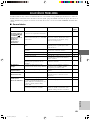 461
461
-
 462
462
-
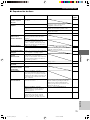 463
463
-
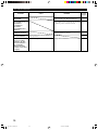 464
464
-
 465
465
-
 466
466
-
 467
467
-
 468
468
-
 469
469
-
 470
470
-
 471
471
-
 472
472
-
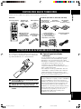 473
473
-
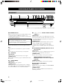 474
474
-
 475
475
-
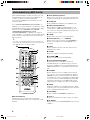 476
476
-
 477
477
-
 478
478
-
 479
479
-
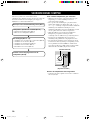 480
480
-
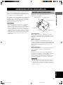 481
481
-
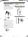 482
482
-
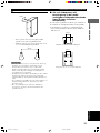 483
483
-
 484
484
-
 485
485
-
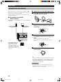 486
486
-
 487
487
-
 488
488
-
 489
489
-
 490
490
-
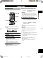 491
491
-
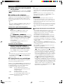 492
492
-
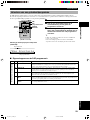 493
493
-
 494
494
-
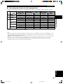 495
495
-
 496
496
-
 497
497
-
 498
498
-
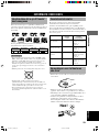 499
499
-
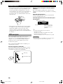 500
500
-
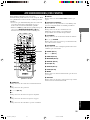 501
501
-
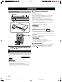 502
502
-
 503
503
-
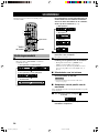 504
504
-
 505
505
-
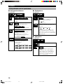 506
506
-
 507
507
-
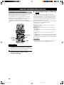 508
508
-
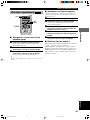 509
509
-
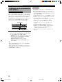 510
510
-
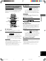 511
511
-
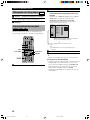 512
512
-
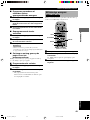 513
513
-
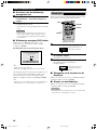 514
514
-
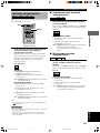 515
515
-
 516
516
-
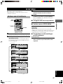 517
517
-
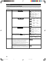 518
518
-
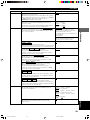 519
519
-
 520
520
-
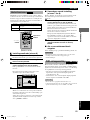 521
521
-
 522
522
-
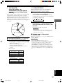 523
523
-
 524
524
-
 525
525
-
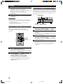 526
526
-
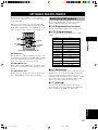 527
527
-
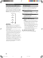 528
528
-
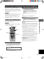 529
529
-
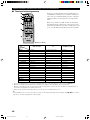 530
530
-
 531
531
-
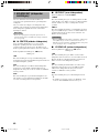 532
532
-
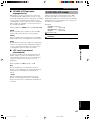 533
533
-
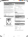 534
534
-
 535
535
-
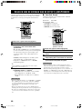 536
536
-
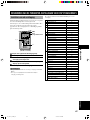 537
537
-
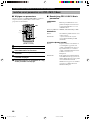 538
538
-
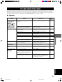 539
539
-
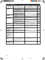 540
540
-
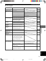 541
541
-
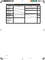 542
542
-
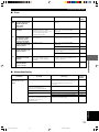 543
543
-
 544
544
-
 545
545
-
 546
546
-
 547
547
-
 548
548
-
 549
549
-
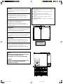 550
550
-
 551
551


Yamaha DVX-S100 Manualul proprietarului
- Categorie
- DVD playere
- Tip
- Manualul proprietarului
în alte limbi
- Türkçe: Yamaha DVX-S100 El kitabı
- français: Yamaha DVX-S100 Le manuel du propriétaire
- English: Yamaha DVX-S100 Owner's manual
- Deutsch: Yamaha DVX-S100 Bedienungsanleitung
- italiano: Yamaha DVX-S100 Manuale del proprietario
- español: Yamaha DVX-S100 El manual del propietario
- svenska: Yamaha DVX-S100 Bruksanvisning
- dansk: Yamaha DVX-S100 Brugervejledning
- Nederlands: Yamaha DVX-S100 de handleiding
Lucrări înrudite
-
Yamaha RX-V520RDS Manual de utilizare
-
-
-
Yamaha AVXS80 Manual de utilizare
-
-
-
-
Yamaha NX-S100S Manual de utilizare
-