
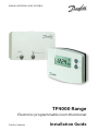
TP4000 Range
Electronic programmable room thermostat
Danfoss Heating
MAKING MODERN LIVING POSSIBLE
Installation Guide

TP4000
2
For a large print version of these instructions
please call Marketing on 0845 121 7400.
Danfoss can accept no responsibility for possible errors in catalogues, brochures, and other
printed material. All trademarks in this material are property of the respective companies.
Danfoss and the Danfoss logotype are trademarks of Danfoss A/S. All rights reserved.

Danfoss Heating
3
GB
FR
ES
NL
GR
PL
CZ
TR
HR
RO
GB
1.0 Product Specifi cation ...................................4
2.0 Installation ....................................................5
2.1 Thermostat Wiring (Hard wired model only) ......................5
2.2 RX Receiver Wiring (RF models only) ....................................6
3.0 Commissioning (RF models only) ...............6
4.0 TP4000/TP4000 RF Programming...............7
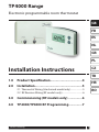
TP4000 Range
Electronic programmable room thermostat
Installation Instructions

TP4000
4
GB
FR
ES
NL
GR
PL
CZ
TR
HR
RO
GB
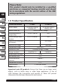
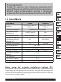
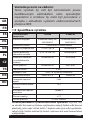
1.0 Product Specifi cation
Please Note:
This product should only be installed by a qualifi ed
electrician or competent heating installer and should
be in accordance with the current edition of the IEEE
wiring regulations.
Thermostat features TP4000 TP4000 RF
Power supply 2 x AA/MN1500/LR
alkaline cells
2 x AA/MN1500/LR
alkaline cells
Memory back-up 1 min for battery change
Switching action of
output relay
1 x SPDT, Type 1B N/A
Switch rating of relay
contact
3(1)A, 10-230Vac N/A
Transmission frequency
(RF Models)
433.92MHz
Transmission range 30m max
Temperature range Off , 5-30°C
Dimensions, mm 110 wide, 88 high, 28 deep
Design standard EN60730-2-9 EN300220
Rated impulse voltage 2.5kV
Ball hardness test 75°C
Control pollution
situation
Degree 2
Temperature accuracy ±1°C
Time accuracy ±1 min. per month
Important note RF products: Ensure that there are no large metal
objects, such as boiler cases or other large appliances, in line of
sight between the transmitter and receiver as these will prevent
communication between thermostat and receiver.

Danfoss Heating
5
GB
FR
ES
NL
GR
PL
CZ
TR
HR
RO
GB
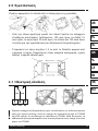
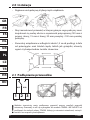
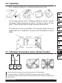
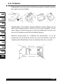
2.0 Installation
· First, remove the wallplate from the back of the unit.
· From the top left hand corner of the wallplate, there must be
clearances of at least 150mm to the right, 15mm to the left,
30mm above and 100mm below in order to mount the plug-in
module.
· Fix at a height of approximately 1.5m from the fl oor, away from
draughts or heat sources such as radiators, open fi res or direct
sunlight.
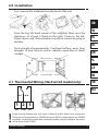
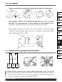
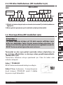
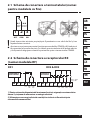
2.1 Thermostat Wiring (Hard wired model only)
1
OFF
23
COM ON
N/C
N/O
!
Some existing thermostats will have a Neutral and/or Earth wire connected.
These are not required by the TP4000 and must NOT be connected to any TP4000
terminals. Instead they should be made electrically safe and coiled in the recess
at the back of the TP4000.

TP4000
6
GB
FR
ES
NL
GR
PL
CZ
TR
HR
RO
GB
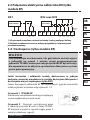
3.0 Commissioning (RF models only)
If the thermostat and the receiver have been supplied together
in a combined pack, the units have been paired in the factory
and no commissioning is required (RX1 only).
To make the RX receiver learn the thermostat’s signal, follow steps 1-5
below.
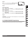
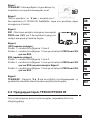
Step 1
TP4000-RF - Reset the unit by pressing the recessed reset button.
Step 2
Press and hold V and + buttons for 3 seconds
(TP4000 RF now transmits unique signal
continuously for 3 minutes).
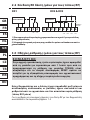
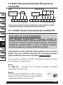
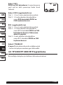
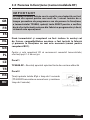
RX1
RX2 & RX3
12
3
4
ELECTRONICS
N
L
COM
ZONE
1 ON
ZONE
1 OFF
A
ELECTRONICS
B
C1
2
345
6
N
L
ZONE
1 ON
ZONE
1 OFF
ZONE
2 ON
ZONE
3 ON
COM
TERMINAL 6
RX3 ONLY
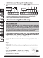
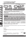
2.2 RX Receiver Wiring (RF models only)
1) For mains voltage operated systems link terminal 2 to mains live supply.
2) Power supply to unit must not be switched by timeswitch.
IMPORTANT
On initial installation, or if the batteries have been removed
from the unit for more than 1 minute before beginning
programming or commissioning the TP4000 unit; it is essential
that the RESET button be pressed to ensure the factory preset
programmes are set and the system is fully operational.

Danfoss Heating
7
GB
FR
ES
NL
GR
PL
CZ
TR
HR
RO
GB
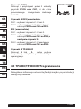
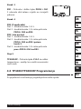
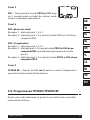
Step 3
RX1 - Press and hold buttons PROG and CH1 for
3 seconds until green light fl ashes once.
Step 4
RX2 (if applicable)
Stat 1 - perform steps 1-3 and 5.
Stat 2 - perform steps 1-2 and then press PROG and CH2 on RX2.
RX3 (if applicable)
Stat 1 - perform steps 1-3 and 5.
Stat 2 - perform steps 1-2 and then press PROG and CH2 on RX3
then step 5.
Stat 3 - perform steps 1-2 and then press PROG and CH3 on RX3.
Step 5
TP4000-RF - Press V or Λ to select temperature - the unit will revert
back to operating mode.
4.0 TP4000/TP4000 RF Programming
For details of this function, please refer to the user instructions.

TP4000
8
GB
FR
ES
NL
GR
PL
CZ
TR
HR
RO
FR
Instructions d’installation
1.0 Spécifi cations ............................................... 9
2.0 Installation ..................................................10
2.1 Câblage ...........................................................................................10
2.2 Câblage du récepteur RX (modèles RF uniquement)....11
3.0 Mise en service (modèles RF uniquement) ..11
4.0 Programmation TP4000/TP4000-RF .........12
TP4000 Range
Thermostat d’ambiance électronique
programmable

Danfoss Heating
9
GB
FR
ES
NL
GR
PL
CZ
TR
HR
RO
FR
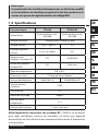
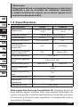
1.0 Spécifi cations
Remarque:
Ce produit doit être installé exclusivement par un électricien qualifi é
ou un installateur de chauff age compétent et doit être conforme à la
version en vigueur des réglementations de câblage IEEE.
Caractéristiques TP4000 TP4000 RF
Alimentation
2 piles alcalines x AA/
MN1500
2 piles alcalines x AA/
MN1500
Réserve mémoire 1 minute, pour changer les piles
Type de contact
1 x SPDT, Type 1B S/O
Caractéristique de
contact
3(1)A, 10-230Vac S/O
Fréquence de
l’émetteur (modèles RF)
S/O 433.92MHz
Portée de l’émetteur
(modèles RF)
S/O 30m max
Plage de températures Off , 5-30°C
Dimensions, mm 110 larg, 88 haut, 28 épaiss
Normes de fabrication EN60730-2-9 EN300220 for RF
Tension de choc
nominale
2.5kV
Essai à la bille 75°C
Niveau de recyclage Degré 2
Précision de la
température
±1°C
Précision de l’horloge ±1 min. par mois
Note importante concernant les systèmes RF : Veiller à ce qu’aucun
gros objet métallique (caisson de chaudière ou autre gros appareil
domestique) ne fasse obstacle aux communications entre le thermostat
et le récepteur.

TP4000
10
GB
FR
ES
NL
GR
PL
CZ
TR
HR
RO
FR
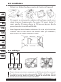
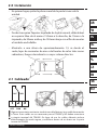
2.0 Installation
• Retirez tout d’abord la plaque murale de l’arrière de l’appareil.
• Par rapport au coin gauche supérieur de la plaque murale, vous
devez disposer d’espacements d’au moins 150 mm à droite, 15
mm à gauche, 30 mm au-dessus et 100 mm en-dessous afi n de
pouvoir monter le module enfi chable.
• Fixez l’appareil à une hauteur d’environ 1,5 m du sol, à l’écart des
courants d’air ou des sources de chaleur telles que radiateurs,
feux ouverts ou lumière directe du soleil.
!
2.1 Câblage
1
OFF
23
COM ON
N/C
N/O
Certains thermostats existants compteront un câble Neutre et/ou Terre connecté.
Ces derniers ne sont pas nécessaires au modèle TP4000 et NE doivent PAS être
connectés à l’une des bornes du TP4000. Ils doivent en revanche être isolés et
enroulés dans le renfoncement à l’arrière du TP4000.

Danfoss Heating
11
GB
FR
ES
NL
GR
PL
CZ
TR
HR
RO
FR
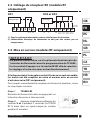
RX1
RX2 et RX3
12
3
4
Electronique
N
L
COM
Zone 1
Marche
Zone 1
Arrét
A
Electronique
B
C1
2
345
6
N
L
Zone 1
Marche
Zone 1
Arrêt
Zone 2
Marche
Zone 3
Marche
COM
Borne 6 RX3
uniquement
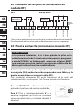
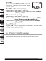
2.2 Câblage du récepteur RX (modèles RF
uniquement)
1) Pour les systèmes à alimentation secteur, relier la borne 2 à la tension.
2) L’alimentation électrique du thermostat ne doit pas être activée par un
temporisateur.
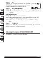
IMPORTANT
A la première installlation , ou si les piles ont été retirées plus de
1 minutes du thermostat avant la programmation du TP 4000 ,
il est essentiel d’appuyer sur la touche RESET afi n de remettre
les réglages d’usine et assurer un bon fonctionnement.
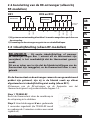
3.0 Mise en service (modèles RF uniquement)
Si le thermostat et le récepteur ont été livrés en un seul ensemble,
les unités ont été couplées en usine et aucune mise en service
n’est nécessaire (RX1 uniquement).
Pour coupler manuellement le récepteur au thermostat émetteur , suivre
les cinq étapes suivantes.
Etape 1 TP4000-RF
Remettre le thermostat à zéro en appuyant sur
le bouton de remise à zéro encastré.
Etape 2 Appuyer et maintenir enfoncées les
touches V et + pendant 3 secondes (le TP4000
RF Si émet alors un signal unique en continu
pendant 3 minutes)

TP4000
12
GB
FR
ES
NL
GR
PL
CZ
TR
HR
RO
FR
Etape 3 RX1
Appuyer et maintenir enfoncées les touches
PROG et CH1 pendant 3 secondes jusqu’à ce que
le témoin lumineux vert clignote une fois.
Etape 4 RX2 (le cas échéant)
Stat 1 - eff ectuer les opérations 1-3 et 5.
Stat 2 - eff ectuer les opérations 1-2 puis appuyer sur PROG et CH2
sur RX2.
RX3 (le cas échéant)
Stat 1 - eff ectuer les opérations 1-3 et 5.
Stat 2 - eff ectuer les opérations 1-2 puis appuyer sur PROG et CH2
sur RX3 puis eff ectuer l’opération 5.
Stat 3 - eff ectuer les opérations 1-2 puis appuyer sur PROG et CH3 sur
RX3.
Etape 5 TP4000-RF
Appuyer sur V ou Λ pour choisir la température – le thermostat
revient à son mode de fonctionnement.
4.0 Programmation TP4000/TP4000-RF
Voir la notice utilisateur pour plus de détail.

Danfoss Heating
13
GB
FR
ES
NL
GR
PL
CZ
TR
HR
RO
ES
1.0 Especifi caciones .........................................14
2.0 Instalación ..................................................15
2.1 Cableado ......................................................................................15
2.2 Cableado del receptor RX (únicamente en modelos RF) . 16
3.0 Puesta en marcha (únicamente modelos RF) 16
4.0 Programación TP4000/TP4000RF .............17
Instrucciones de instalación
TP4000 Range
Cronotermostato

TP4000
14
GB
FR
ES
NL
GR
PL
CZ
TR
HR
RO
ES
1.0 Especifi caciones
Observe que:
Este producto deberá ser instalado solamente por un electricista
cualifi cado o por un instalador de calefacción competente
y deberá instalarse de acuerdo con la edición vigente de las
normas de cableado de la IEEE.
Especifi caciones TP4000 TP4000 RF
Alimentación
2 pilas AA / MIN 1500
/ LR 6
2 pilas AA / MIN 1500
/ LR 6
Respaldo de batería 1 minuto, para cambio de batería
Tipo de contacto
1 x SPDT N/D
Carga de los contactos 3(1)A, 10-230Vac N/D
Frecuencia de
transmisión (en los
modelos RF)
N/D 433.92MHz
Alcance de transmisión
(en los modelos RF)
N/D Máximo 30 m
Rango de temperatura OFF, 5-30°C
Dimensiones generales
(mm)
110 An, 88 Al, 29 Pr
Norma de fabricación EN60730-2-9 EN300220
Tensión nominal del
impulso
2.5kV
Ensayo de presión con
bola
75°C
Control antipolución Grado 2
Precisión de
temperatura
±1°C
Exactitud en la hora ±1 min. p/mes
Nota importante acerca de los productos RF: Asegúrese de que no
haya grandes objetos metálicos tales como equipos calentadores de
agua u otros grandes artefactos que obstaculicen la línea de visión entre
el transmisor y el receptor pues impedirían la comunicación entre el
termostato y el receptor.

Danfoss Heating
15
GB
FR
ES
NL
GR
PL
CZ
TR
HR
RO
ES
2.0 Instalación
· En primer lugar, quitar la placa mural de la parte trasera de la
unidad.
· Desde la esquina superior izquierda de la placa mural, debe haber
un espacio libre de al menos 150mm a la derecha, de 15mm a la
izquierda, de 30mm arriba y de 100mm abajo con el fi n de montar
el módulo enchufable.
· Montarlo a una altura de aproximadamente 1,5 m desde el
suelo, lejos de corrientes de aire o de fuentes de calor tales como
radiadores, fuegos descubiertos o rayos solares directos.
2.1 Cableado
1
OFF
23
COM ON
N/C
N/O
!
Algunos termostatos existentes tendrán un cable Neutro y/o un cable de conexión
a Tierra. Estos cables no son necesarios para el TP4000 y NO deben conectarse
a ningún terminal del TP4000. En lugar de eso los cables deberán aislarse
eléctricamente de modo seguro y enrollarse dentro de un hueco en la parte
trasera del TP4000.

TP4000
16
GB
FR
ES
NL
GR
PL
CZ
TR
HR
RO
ES
RX2 y RX3
12
3
4
Electrónica
N
L
ZONA 1 ENCENDIDA
COMÚN
ZONA 1 APAGADA
A
Electrónica
B
C1
2
345
6
N
L
ZONA 1 ENCENDIDA
COMÚN
TERMINAL 6
ÚNICAMENTE
EN RX3
ZONA 1 APAGADA
ZONA 2 ENCENDIDA
ZONA 3 ENCENDIDA
2.2 Cableado del receptor RX (únicamente en
modelos RF)
1) Para sistemas que funcionen con tensión de red, conecte la alimentación al terminal 2.
2) La alimentación eléctrica a la unidad no debe interrumpirse con un temporizador.
3.0 Puesta en marcha (únicamente modelos RF)
Si el cronotermostato y el receptor han sido suministrados como
un conjunto (Kit), ambos han sido emparejados en la fábrica y la
puesta en marcha no es necesaria (sólo RX1).
Para sintonizar el receptor RX en la frecuencia de la señal del
cronotermostato, siga los pasos 1 al 5 que se indican a continuación.
IMPORTANTE
En la primera instalación , ó si se han quitado las pilas de la
unidad durante más de 1 minuto antes de empezar a programar
la unidad TP4000; es fundamental presionar el boton RESET
para asegurar que estan fi jados los programas establecidos de
fábrica y el sistema funciona completamente.
Paso 1 TP4000-RF - Reinicie la unidad
pulsando el pulsador de reinicio embutido.
Paso 2 Pulse y mantenga pulsados V y +
durante 3 segundos (el TP4000 RF transmite
ahora una señal única y continua durante 3
minutos).
RX1

Danfoss Heating
17
GB
FR
ES
NL
GR
PL
CZ
TR
HR
RO
ES
Paso 3 RX1 - Pulse y mantenga pulsados
PROG y CH1 durante 3 segundos hasta que la
luz verde emita un destello.
Paso 4 RX2 (si es aplicable)
Receptor 1 - ejecute los pasos 1 a 3 y 5.
Receptor 2 - los pasos 1 y 2 y luego pulse PROG y CH2 en el RX2.
RX3 (si es aplicable)
Receptor 1 - ejecute los pasos 1 a 3 y 5.
Receptor 2 - ejecute los pasos 1 y 2, seguidamente pulse PROG y
CH2 en el RX3 y luego ejecute el paso 5.
Receptor 3 - ejecute los pasos 1 y 2 y luego pulse PROG y CH3 en
el RX3.
Paso 5 TP4000-RF
Pulse V o Λ para seleccionar la temperatura; la unidad volverá al modo
operativo.
4.0 Programación TP4000/TP4000RF
Para ver los detalles de esta función, por favor, lease las
instrucciones de usuario.

TP4000
18
GB
FR
ES
NL
GR
PL
CZ
TR
HR
RO
NL
Installatie handleiding
1.0 Technische specifi caties .............................19
2.0 Montage ......................................................20
2.1 Aansluiting .................................................................................. 20
2.2 Aansluiting van de RX-ontvanger (alleen bij RF-modellen) .. 21
3.0 Inbedrijfstelling (alleen RF-modellen) .....21
4.0 TP4000/TP4000RF Instellen ......................22
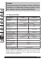
TP4000 Range
Programmeerbare
kamer thermostaat

Danfoss Heating
19
GB
FR
ES
NL
GR
PL
CZ
TR
HR
RO
NL
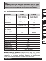
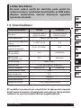
1.0 Technische specifi caties
N.B.:
Dit product dient alleen te worden geïnstalleerd door een erkend
elektrotechnicus of een vakkundige verwarmingsinstallateur
conform de thans geldende IEEE-voorschriften voor bedrading.
Omschrijving TP4000 TP4000 RF
Voeding
2 x AA / MN1500
Alkaline batterijen
2 x AA / MN1500
Alkaline batterijen
Programma backup 1 minuut, voor wisselen batterijen
Relaiscontact
SPDT Type 1B
potentiaalvrij
n.v.t.
Maximum
contactbelasting
10-230Vac, 3(1)A n.v.t.
Bedrijfsfrequentie
(RF-modellen)
n.v.t. 433.92MHz
Zendbereik (RF-
modellen)
n.v.t. 30m max.
Temperatuurbereik Off , 5-30°C
Afmetingen (bxhxd) 110 x 88 x 29mm
Constructienorm EN60730-2-9 EN300220
Nominale piekspanning 2,5kV
Kogeldruktest 75°C
Stralingsniveau Graad 2
Nauwkeurigheid ±1°C
Tijdnauwkeurigheid ±1 min. per maand
Belangrijk voor RF-modellen: Let erop dat zich geen grote metalen
voorwerpen zoals ketels of andere grote apparaten in de zichtlijn tussen
thermostaat en ontvanger bevinden, aangezien de communicatie
tussen thermostaat en ontvanger hierdoor wordt verhinderd.

TP4000
20
GB
FR
ES
NL
GR
PL
CZ
TR
HR
RO
NL
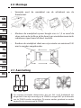
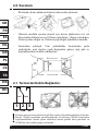
2.0 Montage
• Verwijder eerst de wandplaat van de achterkant van de
thermostaat.
• Monteer de wandplaat op een hoogte van ca. 1,5 m vanaf de
vloer, niet op de tocht en uit de buurt van warmtebronnen zoals
radiatoren, open haard of direct zonlicht.
• Rondom de wandplaat dient een vrije ruimte van minimaal 140
mm te worden aangehouden.
2.1 Aansluiting
1
OFF
23
COM ON
N/C
N/O
!
Op sommige bestaande thermostaten kan een Nul- en/of Aardedraad zijn
aangesloten. Deze zijn niet nodig op de TP4000 en mogen NIET op de klemmen
van de TP4000 worden aangesloten. Zij moeten worden geïsoleerd en worden
opgerold in de uitsparing van de TP4000.
Pagina se încarcă...
Pagina se încarcă...
Pagina se încarcă...
Pagina se încarcă...
Pagina se încarcă...
Pagina se încarcă...
Pagina se încarcă...
Pagina se încarcă...
Pagina se încarcă...
Pagina se încarcă...
Pagina se încarcă...
Pagina se încarcă...
Pagina se încarcă...
Pagina se încarcă...
Pagina se încarcă...
Pagina se încarcă...
Pagina se încarcă...
Pagina se încarcă...
Pagina se încarcă...
Pagina se încarcă...
Pagina se încarcă...
Pagina se încarcă...
Pagina se încarcă...
Pagina se încarcă...
Pagina se încarcă...
Pagina se încarcă...
Pagina se încarcă...
Pagina se încarcă...
Pagina se încarcă...
Pagina se încarcă...
Pagina se încarcă...
Pagina se încarcă...
Pagina se încarcă...
Pagina se încarcă...
Pagina se încarcă...
Pagina se încarcă...
-
 1
1
-
 2
2
-
 3
3
-
 4
4
-
 5
5
-
 6
6
-
 7
7
-
 8
8
-
 9
9
-
 10
10
-
 11
11
-
 12
12
-
 13
13
-
 14
14
-
 15
15
-
 16
16
-
 17
17
-
 18
18
-
 19
19
-
 20
20
-
 21
21
-
 22
22
-
 23
23
-
 24
24
-
 25
25
-
 26
26
-
 27
27
-
 28
28
-
 29
29
-
 30
30
-
 31
31
-
 32
32
-
 33
33
-
 34
34
-
 35
35
-
 36
36
-
 37
37
-
 38
38
-
 39
39
-
 40
40
-
 41
41
-
 42
42
-
 43
43
-
 44
44
-
 45
45
-
 46
46
-
 47
47
-
 48
48
-
 49
49
-
 50
50
-
 51
51
-
 52
52
-
 53
53
-
 54
54
-
 55
55
-
 56
56


