
DTW700
DTW700XV
DTW701
DTW701XV
EN Cordless Impact Wrench INSTRUCTION MANUAL 5
PL Akumulatorowy klucz
udarowy INSTRUKCJA OBSŁUGI 14
HU Akkumulátoros csavarkulcs HASZNÁLATI KÉZIKÖNYV 24
SK Akumulátorový razový
uťahovač NÁVOD NA OBSLUHU 33
CS Akumulátorový rázový
utahovák NÁVOD K OBSLUZE 42
UK Бездротовий ударний
гайковерт ІНСТРУКЦІЯ З
ЕКСПЛУАТАЦІЇ 51
RO Maşină de înşurubat cu
impact cu acumulator MANUAL DE INSTRUCŢIUNI 61
DE Akku-Schlagschrauber BETRIEBSANLEITUNG 70

2
1
2
3
Fig.1
1
2
Fig.2
1
Fig.3
1
Fig.4
1
Fig.5
1
A
B
Fig.6
Fig.7

3
Fig.8
12
Fig.9
1
2
3
Fig.10
1
2
3
Fig.11
1
3
3
4
4
2
Fig.12
1
3
3
4
4
2
Fig.13
2
3
1
Fig.14
1
Fig.15

4
1
2
3
Fig.16
Fig.17

5ENGLISH
ENGLISH (Original instructions)
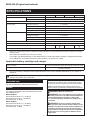
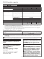
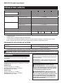
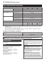
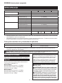
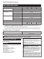
SPECIFICATIONS
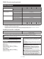
Model: DTW700 DTW700XV DTW701 DTW701XV
Fastening capacities Standard bolt M10 - M24
High tensile bolt M10 - M16
Square drive 12.7 mm
No load speed Max impact mode (4) 0 - 2,200 min-1
Hard impact mode (3) 0 - 1,900 min-1
Medium impact mode (2) 0 - 1,200 min-1
Soft impact mode (1) 0 - 500 min-1
Impacts per minute Max impact mode (4) 0 - 2,700 min-1
Hard impact mode (3) 0 - 2,400 min-1
Medium impact mode (2) 0 - 1,700 min-1
Soft impact mode (1) 0 - 1,000 min-1
Overall length 170 mm
Rated voltage D.C. 18 V
For use near high-voltage electrical power lines --
Net weight 2.3 - 2.7 kg
• Duetoourcontinuingprogramofresearchanddevelopment,thespecicationshereinaresubjecttochange
without notice.
• Specicationsmaydierfromcountrytocountry.
• Theweightmaydierdependingontheattachment(s),includingthebatterycartridge.Thelightestandheavi-
est combinations, according to EPTA-Procedure 01/2014, are shown in the table.
Applicable battery cartridge and charger
Batterycartridge BL1815N / BL1820B / BL1830B / BL1840B / BL1850B / BL1860B
Charger DC18RC / DC18RD / DC18RE / DC18SD / DC18SE / DC18SF /
DC18SH / DC18WC
• Someofthebatterycartridgesandchargerslistedabovemaynotbeavailabledependingonyourregionof
residence.
WARNING: Only use the battery cartridges and chargers listed above.Useofanyotherbatterycartridges
andchargersmaycauseinjuryand/orre.
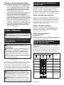
Intended use
The tool is intended for fastening bolts and nuts.
Noise
ThetypicalA-weightednoiseleveldeterminedaccord-
ing to EN62841-2-1:
Model DTW700
Sound pressure level (LpA) : 94 dB (A)
Sound power level (LWA) : 105 dB (A)
Uncertainty(K):3dB(A)
Model DTW701
Sound pressure level (LpA) : 94 dB(A)
Sound power level (LWA) : 105 dB (A)
Uncertainty(K):3dB(A)
NOTE:
The declared noise emission value(s) has been
measured in accordance with a standard test method
andmaybeusedforcomparingonetoolwithanother.
NOTE:
Thedeclarednoiseemissionvalue(s)may
alsobeusedinapreliminaryassessmentofexposure.
WARNING: Wear ear protection.
WARNING: The noise emission during actual
use of the power tool can dier from the declared
value(s) depending on the ways in which the
tool is used especially what kind of workpiece is
processed.
WARNING: Be sure to identify safety mea-
sures to protect the operator that are based on an
estimation of exposure in the actual conditions of
use (taking account of all parts of the operating
cycle such as the times when the tool is switched
o and when it is running idle in addition to the
trigger time).

6ENGLISH
Vibration
The vibration total value (tri-axial vector sum) deter-
mined according to EN62841-2-1:
Model DTW700
Work mode: impact tightening of fasteners of the maxi-
mumcapacityofthetool
Vibration emission (ah) : 19.0 m/s2
Uncertainty(K):2.0m/s2
Model DTW701
Work mode: impact tightening of fasteners of the maxi-
mumcapacityofthetool
Vibration emission (ah) : 19.0 m/s2
Uncertainty(K):2.0m/s2
NOTE: The declared vibration total value(s) has been
measured in accordance with a standard test method
andmaybeusedforcomparingonetoolwithanother.
NOTE:Thedeclaredvibrationtotalvalue(s)mayalso
beusedinapreliminaryassessmentofexposure.
WARNING: The vibration emission during
actual use of the power tool can dier from the
declared value(s) depending on the ways in which
the tool is used especially what kind of workpiece
is processed.
WARNING: Be sure to identify safety mea-
sures to protect the operator that are based on an
estimation of exposure in the actual conditions of
use (taking account of all parts of the operating
cycle such as the times when the tool is switched
o and when it is running idle in addition to the
trigger time).
EC Declaration of Conformity
For European countries only
TheECdeclarationofconformityisincludedasAnnexA
to this instruction manual.
SAFETY WARNINGS
General power tool safety warnings
WARNING: Read all safety warnings, instruc-
tions, illustrations and specications provided
with this power tool. Failure to follow all instructions
listedbelowmayresultinelectricshock,reand/or
seriousinjury.
Save all warnings and instruc-
tions for future reference.
Theterm"powertool"inthewarningsreferstoyour
mains-operated(corded)powertoolorbattery-operated
(cordless) power tool.
Cordless impact wrench safety
warnings
1. Hold the power tool by insulated gripping
surfaces, when performing an operation
where the fastener may contact hidden wiring.
Fastenerscontactinga"live"wiremaymake
exposed metal parts of the power tool "live" and
could give the operator an electric shock.
2. Wear ear protectors.
3. Check the impact socket carefully for wear,
cracks or damage before installation.
4. Hold the tool rmly.
5. Keep hands away from rotating parts.
6. Do not touch the impact socket, bolt, nut or the
workpiece immediately after operation.They
maybeextremelyhotandcouldburnyourskin.
7. Always be sure you have a rm footing.
Be sure no one is below when using the tool in
high locations.
8. The proper fastening torque may dier
depending upon the kind or size of the bolt.
Check the torque with a torque wrench.
9. Make sure there are no electrical cables, water
pipes, gas pipes etc. that could cause a hazard
if damaged by use of the tool.
SAVE THESE INSTRUCTIONS.
WARNING: DO NOT let comfort or familiarity
with product (gained from repeated use) replace
strict adherence to safety rules for the subject
product.
MISUSE or failure to follow the safety rules stated
in this instruction manual may cause serious
personal injury.
Important safety instructions for
battery cartridge
1. Before using battery cartridge, read all instruc-
tions and cautionary markings on (1) battery
charger, (2) battery, and (3) product using
battery.
2. Do not disassemble or tamper with the battery
cartridge.Itmayresultinare,excessiveheat,
or explosion.
3. If operating time has become excessively
shorter, stop operating immediately. It may
result in a risk of overheating, possible burns
and even an explosion.
4. If electrolyte gets into your eyes, rinse them
out with clear water and seek medical atten-
tion right away. It may result in loss of your
eyesight.
5. Do not short the battery cartridge:
(1) Do not touch the terminals with any con-
ductive material.
(2) Avoid storing battery cartridge in a con-
tainer with other metal objects such as
nails, coins, etc.
(3) Do not expose battery cartridge to water
or rain.

7ENGLISH
A battery short can cause a large current
ow, overheating, possible burns and even a
breakdown.
6. Do not store and use the tool and battery car-
tridge in locations where the temperature may
reach or exceed 50 °C (122 °F).
7. Do not incinerate the battery cartridge even if
it is severely damaged or is completely worn
out. The battery cartridge can explode in a re.
8. Do not nail, cut, crush, throw, drop the battery
cartridge, or hit against a hard object to the
battery cartridge.Suchconductmayresultina
re,excessiveheat,orexplosion.
9. Do not use a damaged battery.
10. The contained lithium-ion batteries are subject
to the Dangerous Goods Legislation require-
ments.
Forcommercialtransportse.g.bythirdparties,
forwarding agents, special requirement on pack-
aging and labeling must be observed.
For preparation of the item being shipped, consult-
ing an expert for hazardous material is required.
Pleasealsoobservepossiblymoredetailed
national regulations.
Tapeormaskoopencontactsandpackupthe
batteryinsuchamannerthatitcannotmove
around in the packaging.
11. When disposing the battery cartridge, remove
it from the tool and dispose of it in a safe
place. Follow your local regulations relating to
disposal of battery.
12. Use the batteries only with the products
specied by Makita. Installing the batteries to
non-compliantproductsmayresultinare,exces-
siveheat,explosion,orleakofelectrolyte.
13. If the tool is not used for a long period of time,
the battery must be removed from the tool.
14. During and after use, the battery cartridge may
take on heat which can cause burns or low
temperature burns. Pay attention to the han-
dling of hot battery cartridges.
15. Do not touch the terminal of the tool imme-
diately after use as it may get hot enough to
cause burns.
16. Do not allow chips, dust, or soil stuck into the
terminals, holes, and grooves of the battery
cartridge.Itmaycauseheating,catchingre,
burstandmalfunctionofthetoolorbatterycar-
tridge,resultinginburnsorpersonalinjury.
17. Unless the tool supports the use near
high-voltage electrical power lines, do not use
the battery cartridge near high-voltage electri-
cal power lines.Itmayresultinamalfunctionor
breakdownofthetoolorbatterycartridge.
18. Keep the battery away from children.
SAVE THESE INSTRUCTIONS.
CAUTION: Only use genuine Makita batteries.
Use of non-genuine Makita batteries, or batteries that
havebeenaltered,mayresultinthebatterybursting
causingres,personalinjuryanddamage.Itwill
alsovoidtheMakitawarrantyfortheMakitatooland
charger.
Tips for maintaining maximum
battery life
1. Charge the battery cartridge before completely
discharged. Always stop tool operation and
charge the battery cartridge when you notice
less tool power.
2. Never recharge a fully charged battery car-
tridge. Overcharging shortens the battery
service life.
3. Charge the battery cartridge with room tem-
perature at 10 °C - 40 °C (50 °F - 104 °F). Let
a hot battery cartridge cool down before
charging it.
4. When not using the battery cartridge, remove
it from the tool or the charger.
5. Charge the battery cartridge if you do not use
it for a long period (more than six months).
FUNCTIONAL
DESCRIPTION
CAUTION: Always be sure that the tool is
switched o and the battery cartridge is removed
before adjusting or checking function on the tool.
Installing or removing battery
cartridge
CAUTION: Always switch o the tool before
installing or removing of the battery cartridge.
CAUTION: Hold the tool and the battery car-
tridge rmly when installing or removing battery
cartridge.Failuretoholdthetoolandthebattery
cartridgermlymaycausethemtoslipoyourhands
andresultindamagetothetoolandbatterycartridge
andapersonalinjury.
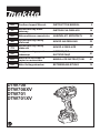
►Fig.1: 1. Red indicator 2. Button 3.Batterycartridge
Toremovethebatterycartridge,slideitfromthetool
while sliding the button on the front of the cartridge.
Toinstallthebatterycartridge,alignthetongueonthe
batterycartridgewiththegrooveinthehousingandslip
itintoplace.Insertitallthewayuntilitlocksinplace
withalittleclick.Ifyoucanseetheredindicatoras
showninthegure,itisnotlockedcompletely.
CAUTION: Always install the battery cartridge
fully until the red indicator cannot be seen. If not,
itmayaccidentallyfalloutofthetool,causinginjuryto
youorsomeonearoundyou.
CAUTION: Do not install the battery cartridge
forcibly.Ifthecartridgedoesnotslideineasily,itis
notbeinginsertedcorrectly.

8ENGLISH
Tool / battery protection system
Thetoolisequippedwithatool/batteryprotectionsys-
tem.Thissystemautomaticallycutsothepowerto
extendtoolandbatterylife.Thetoolwillautomatically
stopduringoperationifthetoolorbatteryisplaced
under one of the following conditions:
Overload protection
This protection works when the tool is operated in a
mannerthatcausesittodrawanabnormallyhighcur-
rent.Inthissituation,turnthetooloandstoptheappli-
cation that caused the tool to become overloaded. Then
turn the tool on to restart.
Overheat protection
Thisprotectionworkswhenthetoolorbatteryisover-
heated.Inthissituation,letthetoolandbatterycool
before turning the tool on again.
Overdischarge protection
Thisprotectionworkswhentheremainingbattery
capacitygetslow.Inthissituation,removethebattery
fromthetoolandchargethebattery.
Indicating the remaining battery
capacity
Only for battery cartridges with the indicator
►Fig.2: 1. Indicator lamps 2. Check button
Pressthecheckbuttononthebatterycartridgetoindi-
catetheremainingbatterycapacity.Theindicatorlamps
light up for a few seconds.
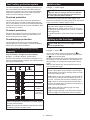
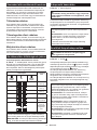
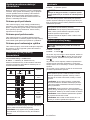
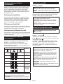
Indicator lamps Remaining
capacity
Lighted O Blinking
75% to 100%
50% to 75%
25% to 50%
0% to 25%
Charge the
battery.
Thebattery
mayhave
malfunctioned.
NOTE: Depending on the conditions of use and the
ambienttemperature,theindicationmaydierslightly
fromtheactualcapacity.
NOTE:Therst(farleft)indicatorlampwillblinkwhen
thebatteryprotectionsystemworks.
Switch action
►Fig.3: 1. Switch trigger
CAUTION: Before installing the battery car-
tridge into the tool, always check to see that the
switch trigger actuates properly and returns to
the "OFF" position when released.
Tostartthetool,simplypulltheswitchtrigger.Tool
speedisincreasedbyincreasingpressureontheswitch
trigger. Release the switch trigger to stop.
NOTE:Thetoolautomaticallystopswhenyoukeep
pulling the switch trigger for 6 minutes.
NOTE: When full speed mode is turned on, the rota-
tionspeedbecomesfastestevenifyoudonotpullthe
switchtriggerfully.
For detail information, refer to the section of full speed
mode.
Lighting up the front lamp
CAUTION: Do not look in the light or see the
source of light directly.
►Fig.4: 1. Lamp
►Fig.5: 1. Button
To turn on the lamp status, press the button for
onesecond.Toturnothelampstatus,pressthebut-
ton for one second again.
With the lamp status ON, pull the switch trigger to turn
onthelamp.Toturno,releaseit.Thelampgoesout
approximately10secondsafterreleasingtheswitch
trigger.
With the lamp status OFF, the lamp does not turn on
even if pulling the trigger.
NOTE:Toconrmthelampstatus,pullthetrigger.
Whenthelamplightsupbypullingtheswitchtrigger,
the lamp status is ON. When the lamp does not come
on, the lamp status is OFF.
NOTE:Whenthetoolisoverheated,thelightashes
foroneminute,andthentheLEDdisplaygoeso.In
this case, cool down the tool before operating again.
NOTE:Useadryclothtowipethedirtothelensof
the lamp. Be careful not to scratch the lens of lamp, or
itmaylowertheillumination.
NOTE: While pulling the switch trigger, the lamp
status cannot be changed.
NOTE:Forapproximately10secondsafterreleasing
the switch trigger, the lamp status can be changed.

9ENGLISH
Reversing switch action
►Fig.6: 1. Reversing switch lever
CAUTION: Always check the direction of
rotation before operation.
CAUTION: Use the reversing switch only after
the tool comes to a complete stop. Changing the
directionofrotationbeforethetoolstopsmaydam-
age the tool.
CAUTION: When not operating the tool,
always set the reversing switch lever to the neu-
tral position.
This tool has a reversing switch to change the direction
of rotation. Depress the reversing switch lever from the
A side for clockwise rotation or from the B side for coun-
terclockwise rotation.
When the reversing switch lever is in the neutral posi-
tion, the switch trigger cannot be pulled.
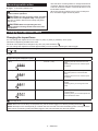
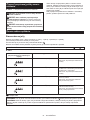
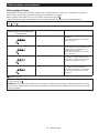
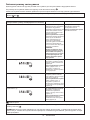
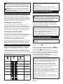
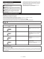
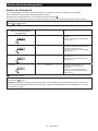
Changing the application mode
Changing the impact force
You can change the impact force in four steps: 4 (max), 3 (hard), 2 (medium), and 1 (soft).
This allows a tightening suitable to the work.
Theleveloftheimpactforcechangeseverytimeyoupressthebutton .
Youcanchangetheimpactforcewithinapproximatelyoneminuteafterreleasingtheswitchtrigger.
NOTE:Youcanextendthetimetochangetheimpactforceapproximatelyoneminuteifyoupressthebut-
ton or .
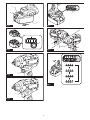
►Fig.7
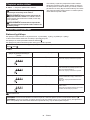
Application mode
(Impact force grade displayed on panel) Maximum blows Purpose
4 (Max) 2,700 min-1 (/min) Tightening with the maximum force and
speed.
Tightening when the force and the speed
are desired.
3 (Hard) 2,400 min-1 (/min) Tightening with less force and speed than
Max mode (easier to control than Max
mode).
Tightening when the force and the speed
are desired.
2 (Medium) 1,700 min-1 (/min) Tighteningwhenagoodnishingis
needed.
Tighteningwhenyouneedgoodcontrol
power.
1 (Soft) 1,000 min-1 (/min) Tightening with less force to avoid screw
thread breakage.
Tighteningwhenyouneedneadjustment
with small diameter bolts.
: The lamp is on.
NOTE: When none of the lamp on the panel is lit, pull the switch trigger once before pressing the button .
NOTE:Alllampsontheswitchpanelgooutwhenthetoolisturnedotosavethebatterypower.Theimpactforce
gradecanbecheckedbypullingtheswitchtriggertotheextentthatthetooldoesnotoperate.

10 ENGLISH
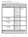
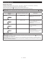
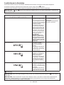
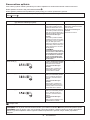
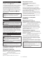
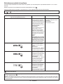
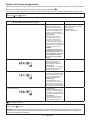
Changing the application mode
Thistoolemploysseveraleasy-to-useapplicationmodesfordrivingboltswithgoodcontrol.
Thetypeoftheapplicationmodechangeseverytimeyoupressthebutton .
Youcanchangetheapplicationmodewithinapproximatelyoneminuteafterreleasingtheswitchtrigger.
NOTE:Youcanextendthetimetochangetheapplicationmodeapproximatelyoneminuteifyoupressthebut-
ton or .
►Fig.8
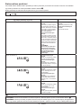
Application mode
(Assist type displayed on panel)
Feature Purpose
Bolt mode Clockwise
This mode helps to repeat
screwdrivingcontinuously
with equal torque. This mode
also helps to reduce the risk of
breakage of bolts/nuts due to
overtightening.
Counterclockwise
This mode helps to prevent a
boltfromfallingo.Whenloos-
ening a bolt with the tool driving
in counterclockwise rotation,
thetoolautomaticallystopsor
slows down after the bolt/nut
gets enough loosened.
NOTE:
The timing to stop the driving
varies depending on the type
of the bolt/nut and material to
be driven. Make a test driving
before using this mode.
Clockwise
Preventing overtightening of
bolts.
Counterclockwise
Loosening bolts.
Bolt mode (1) Clockwise
Thetoolstopsautomaticallyas
soon as it has started impact
blows.
Counterclockwise
The impact force is 4. The tool
stopsautomaticallyassoonas
it has stopped impact blows.
–
Bolt mode (2) Clockwise
Thetoolstopsautomatically
approximately0.5secondlater
from the moment that the tool
has started impact blows.
Counterclockwise
The impact force is 4. The tool
stopsautomaticallyapproxi-
mately0.2secondlaterfrom
the moment that the tool has
stopped impact blows.
–
Bolt mode (3) Clockwise
Thetoolstopsautomatically
approximately1secondlater
from the moment that the tool
has started impact blows.
Counterclockwise
The tool slows down the rota-
tion after it has stopped impact
blows.
–
: The lamp is on.
NOTE: When none of the lamp on the panel is lit, pull the switch trigger once before pressing the button .
NOTE:Alllampsontheswitchpanelgooutwhenthetoolisturnedotosavethebatterypower.Thetypeofthe
applicationmodecanbecheckedbypullingtheswitchtriggertotheextentthatthetooldoesnotoperate.

11 ENGLISH
Full speed mode
►Fig.9: 1. Button 2. Lamp
When full speed mode is turned on, the tool speed becomes
fastestevenifyoudonotpulltheswitchtriggerfully.When
fullspeedmodeisturnedo,thetoolspeedincreasesas
youincreasethepressureontheswitchtrigger.
To turn on full speed mode, press and hold the button . To
turnofullspeedmode,pressandholdthebutton again.
The lamp turns on while full speed mode is on.
NOTE: Full speed mode continues even after switch-
ing the impact force mode/auto stop mode.
ASSEMBLY
CAUTION: Always be sure that the tool is
switched o and the battery cartridge is removed
before carrying out any work on the tool.
Selecting correct impact socket
Alwaysusethecorrectsizeimpactsocketforboltsandnuts.
An incorrect size impact socket will result in inaccurate and
inconsistent fastening torque and/or damage to the bolt or nut.
Installing or removing impact socket
Optional accessory
CAUTION: Make sure that the impact socket
and the mounting portion are not damaged before
installing the impact socket.
CAUTION: After inserting the impact socket,
make sure that it is rmly secured. If it comes out,
do not use it.
NOTE:Thewayofimpactsocketinstallationvaries
dependingonthetypeofthesquaredriveonthetool.
Tool with the ring spring
Model DTW700 / DTW700XV
For impact socket without O-ring and pin
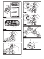
►Fig.10:
1. Impact socket 2. Square drive 3. Ring spring
Push the impact socket onto the square drive until it
locks into place.
Toremovetheimpactsocket,simplypullito.
For impact socket with O-ring and pin
►Fig.11: 1. Impact socket 2. O-ring 3. Pin
Move the O-ring out of the groove in the impact socket
and remove the pin from the impact socket. Fit the impact
socket onto the square drive so that the hole in the impact
socket is aligned with the hole in the square drive.
Insert the pin through the hole in the impact socket and
square drive. Then return the O-ring to the original posi-
tion in the impact socket groove to retain the pin.
To remove the impact socket, follow the installation
procedures in reverse.
Tool with the detent pin
Model DTW701 / DTW701XV
For tool with light t detent pin
►Fig.12: 1. Impact socket 2. Hole 3. Square drive
4. Detent pin
To install the socket, align the hole in the side of the
socket with the detent pin on the square drive, and then,
push it onto the square drive until it locks into place. Tap
itlightlyifrequired.
Toremovethesocket,simplypullito.
For tool with rm t detent pin
Optional accessory
►Fig.13: 1. Impact socket 2. Hole 3. Square drive
4. Detent pin
To install the socket, align the hole in the side of the socket with
the detent pin on the square drive, and then, push it onto the
squaredriveuntilitlocksintoplace.Tapitlightlyifrequired.
To remove the socket, depress the detent pin through the
holeinthesocketandpullthesocketothesquaredrive.
NOTE:Thermtdetentpinmayttoosecurelyto
remove the socket.
Inthatcase,depressthermtdetentpinfullyand
pullthesocketothesquaredrive.
Installing hook
WARNING: Use the hanging/mounting parts
for their intended purposes only, e.g., hanging the
tool on a tool belt between jobs or work intervals.
WARNING: Be careful not to overload the
hook as too much force or irregular overburden
may cause damages to the tool resulting in per-
sonal injury.
CAUTION:
When installing the hook, always
secure it with the screw rmly.Ifnot,thehookmay
comeofromthetoolandresultinthepersonalinjury.
CAUTION:
Make sure to hang the tool securely
before releasing your hold.Insucientorunbalanced
hookingmaycausefallingoandyoumaybeinjured.
►Fig.14: 1. Groove 2. Hook 3. Screw
Thehookisconvenientfortemporarilyhangingthetool.
This can be installed on either side of the tool. To install
the hook, insert it into a groove in the tool housing on
either side and then secure it with a screw. To remove,
loosen the screw and then take it out.
Using hole
WARNING: Never use the hanging hole for
unintended purpose, for instance, tethering the
tool at high location.Bearingstressinaheavily
loadedholemaycausedamagestothehole,result-
ingininjuriestoyouorpeoplearoundorbelowyou.
►Fig.15: 1. Hanging hole
Use the hanging hole at the bottom rear of the tool to
hang the tool on a wall using a hanging cord or similar
strings.

12 ENGLISH
Ring
Country specic
CAUTION: Before using the ring, always
make sure that the bracket and ring are secured
and not damaged.
CAUTION: Use the hanging/mounting parts
for their intended purposes only. Using for unin-
tendedpurposemaycauseaccidentorpersonal
injury.
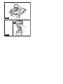
►Fig.16: 1. Bracket 2. Ring 3. Screws
The ring is convenient for hanging the tool with hoist.
First, place the rope through the ring. Then hang the
tool up to the air with hoist.
OPERATION
CAUTION: Always insert the battery cartridge
all the way until it locks in place.Ifyoucanseethe
red indicator on the upper side of the button, it is not
lockedcompletely.Insertitfullyuntiltheredindicator
cannotbeseen.Ifnot,itmayaccidentallyfalloutof
thetool,causinginjurytoyouorsomeonearound
you.
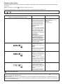
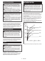
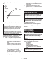
►Fig.17
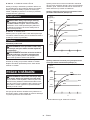
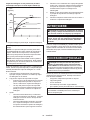
Holdthetoolrmlyandplacetheimpactsocketovertheboltor
nut. Turn the tool on and fasten for the proper fastening time.
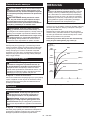
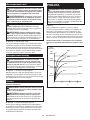
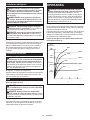
Theproperfasteningtorquemaydierdependingupon
the kind or size of the bolt, the material of the workpiece
to be fastened, etc. The relation between fastening
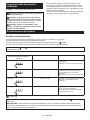
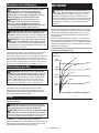
torqueandfasteningtimeisshowninthegures.
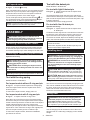
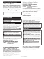
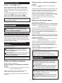
Proper fastening torque for standard bolt with max
impact mode (4)
100
200
300
01
23
(3060)
400
(4080)
(2040)
(1020)
N•m
(kgf•cm)
2
1
M22
M24
(M22)
(M24)
M20
(M20)
M16
(M16)
1. Fastening time (second) 2. Fastening torque
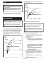
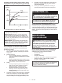
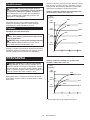
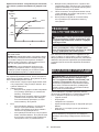
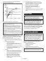
Proper fastening torque for high tensile bolt with
max impact mode (4)
100
200
300
01
23
(3060)
(2040)
(1020)
N•m
(kgf•cm)
2
1
M16
M16
M14
M14
M12
M12
1. Fastening time (second) 2. Fastening torque
NOTE: Hold the tool pointed straight at the bolt or nut.
NOTE:Excessivefasteningtorquemaydamagethe
bolt/nutorimpactsocket.Beforestartingyourjob,
alwaysperformatestoperationtodeterminethe
properfasteningtimeforyourboltornut.
NOTE:Ifthetoolisoperatedcontinuouslyuntilthe
batterycartridgehasdischarged,allowthetooltorest
for15minutesbeforeproceedingwithafreshbattery
cartridge.
Thefasteningtorqueisaectedbyawidevarietyof
factorsincludingthefollowing.Afterfastening,always
check the torque with a torque wrench.
1. Whenthebatterycartridgeisdischargedalmost
completely,voltagewilldropandthefastening
torque will be reduced.
2. Impact socket
• Failure to use the correct size impact socket
will cause a reduction in the fastening torque.
• A worn impact socket (wear on the hex end
or square end) will cause a reduction in the
fastening torque.
3. Bolt
• Eventhoughthetorquecoecientandthe
class of bolt are the same, the proper fasten-
ingtorquewilldieraccordingtothediame-
ter of bolt.
• Even though the diameters of bolts are the
same,theproperfasteningtorquewilldier
accordingtothetorquecoecient,theclass
of bolt and the bolt length.
4. Theuseoftheuniversaljointortheextension
bar somewhat reduces the fastening force of the
impactwrench.Compensatebyfasteningfora
longer period of time.
5. The manner of holding the tool or the material
ofdrivingpositiontobefastenedwillaectthe
torque.
6. Operating the tool at low speed will cause a reduc-
tion in the fastening torque.

13 ENGLISH
MAINTENANCE
CAUTION: Always be sure that the tool is
switched o and the battery cartridge is removed
before attempting to perform inspection or
maintenance.
NOTICE: Never use gasoline, benzine, thinner,
alcohol or the like. Discoloration, deformation or
cracks may result.
To maintain product SAFETY and RELIABILITY,
repairs,anyothermaintenanceoradjustmentshould
beperformedbyMakitaAuthorizedorFactoryService
Centers,alwaysusingMakitareplacementparts.
OPTIONAL
ACCESSORIES
CAUTION: These accessories or attachments
are recommended for use with your Makita tool
specied in this manual.Theuseofanyother
accessories or attachments might present a risk of
injurytopersons.Onlyuseaccessoryorattachment
for its stated purpose.
Ifyouneedanyassistanceformoredetailsregard-
ingtheseaccessories,askyourlocalMakitaService
Center.
• Impact socket
• Extension bar
• Universaljoint
• Makitagenuinebatteryandcharger
• Pin4Set(ForDTW701/DTW701XVonly)
NOTE:Someitemsinthelistmaybeincludedinthe
toolpackageasstandardaccessories.Theymay
dierfromcountrytocountry.

14 POLSKI
POLSKI (Instrukcja oryginalna)
DANE TECHNICZNE
Model: DTW700 DTW700XV DTW701 DTW701XV
Zakresydokręcania Śrubazwykła M10–M24
Śrubaodużejwytrzymałości M10–M16
Zabierakkwadratowy 12,7 mm
Prędkośćbezobciążenia Trybmaksymalnejsiłyudaru(4) 0–2 200 min-1
Trybdużejsiłyudaru(3) 0–1 900 min-1
Trybśredniejsiłyudaru(2) 0–1 200 min-1
Trybmałejsiłyudaru(1) 0–500 min-1
Liczbaudarównaminutę Trybmaksymalnejsiłyudaru(4) 0–2 700 min-1
Trybdużejsiłyudaru(3) 0–2 400 min-1
Trybśredniejsiłyudaru(2) 0–1 700 min-1
Trybmałejsiłyudaru(1) 0–1 000 min-1
Długośćcałkowita 170 mm
Napięcieznamionowe Prądstały18V
Doużytkuwpobliżuliniiwysokiegonapięcia --
Masa netto 2,3–2,7 kg
• Wzwiązkuzestaleprowadzonymprzeznasząrmęprogramembadawczo-rozwojowymniniejszedanemogą
uleczmianombezwcześniejszegopowiadomienia.
• Danetechnicznemogąróżnićsięwzależnościodkraju.
• Masamożebyćróżnawzależnościodosprzętu,wtymakumulatora.Wtabeliprzedstawionajestnajlżejszai
najcięższakonguracja,zgodniezprocedurąEPTA01/2014.
Kompatybilne akumulatory i ładowarki
Akumulator BL1815N / BL1820B / BL1830B / BL1840B / BL1850B / BL1860B
Ładowarka DC18RC / DC18RD / DC18RE / DC18SD / DC18SE / DC18SF /
DC18SH / DC18WC
• Pewnezwymienionychpowyżejakumulatorówiładowarekmogąbyćniedostępnewregioniezamieszkania
użytkownika.
OSTRZEŻENIE: Należy używać wyłącznie akumulatorów i ładowarek wymienionych powyżej.
Używanieinnychakumulatorówiładowarekmożestwarzaćryzykowystąpieniaobrażeńciałalubpożaru.
Przeznaczenie
Narzędziejestprzeznaczonedodokręcaniaśrubi
nakrętek.
Hałas
TypowyrównoważnypoziomdźwiękuAokreślonyw
oparciuonormęEN62841-2-1:
Model DTW700
Poziomciśnieniaakustycznego(LpA): 94 dB(A)
Poziommocyakustycznej(LWA): 105 dB (A)
Niepewność(K):3dB(A)
Model DTW701
Poziomciśnieniaakustycznego(LpA): 94 dB(A)
Poziommocyakustycznej(LWA): 105 dB (A)
Niepewność(K):3dB(A)
WSKAZÓWKA:
Deklarowanawartośćemisjihałasu
zostałazmierzonazgodniezestandardowąmetodątestową
imożnająwykorzystaćdoporównywanianarzędzi.
WSKAZÓWKA:
Deklarowanąwartośćemisjihałasu
możnatakżewykorzystaćwewstępnejocenienarażenia.
OSTRZEŻENIE: Nosić ochronniki słuchu.
OSTRZEŻENIE:
Poziom hałasu wytwarzanego
podczas rzeczywistego użytkowania elektronarzę-
dzia może się różnić od wartości deklarowanej w
zależności od sposobu użytkowania narzędzia, a w
szczególności od rodzaju obrabianego elementu.
OSTRZEŻENIE: W oparciu o szacowane
narażenie w rzeczywistych warunkach użytkowa-
nia należy określić środki bezpieczeństwa w celu
zapewnienia ochrony operatora (uwzględniając
wszystkie elementy cyklu działania, tj. czas, kiedy
narzędzie jest wyłączone i kiedy pracuje na biegu
jałowym, a także czas, kiedy jest włączone).

15 POLSKI
Drgania
Całkowitawartośćpoziomudrgań(sumawektoróww3
osiach)określonazgodnieznormąEN62841-2-1:
Model DTW700
Trybpracy:dokręcanieudaroweśrubiwkrętówwmak-
symalnymzakresiemożliwościnarzędzia
Emisjadrgań(ah): 19,0 m/s2
Niepewność(K):2,0m/s2
Model DTW701
Trybpracy:dokręcanieudaroweśrubiwkrętówwmak-
symalnymzakresiemożliwościnarzędzia
Emisjadrgań(ah): 19,0 m/s2
Niepewność(K):2,0m/s2
WSKAZÓWKA:Deklarowanawartośćpoziomu
drgańzostałazmierzonazgodniezestandardową
metodątestowąimożnająwykorzystaćdoporówny-
wanianarzędzi.
WSKAZÓWKA:Deklarowanąwartośćpoziomu
drgańmożnatakżewykorzystaćwewstępnejocenie
narażenia.
OSTRZEŻENIE: Drgania wytwarzane pod-
czas rzeczywistego użytkowania elektronarzędzia
mogą się różnić od wartości deklarowanej w
zależności od sposobu użytkowania narzędzia,
a w szczególności od rodzaju obrabianego
elementu.
OSTRZEŻENIE: W oparciu o szacowane
narażenie w rzeczywistych warunkach użytkowa-
nia należy określić środki bezpieczeństwa w celu
zapewnienia ochrony operatora (uwzględniając
wszystkie elementy cyklu działania, tj. czas, kiedy
narzędzie jest wyłączone i kiedy pracuje na biegu
jałowym, a także czas, kiedy jest włączone).
Deklaracja zgodności WE
Dotyczy tylko krajów europejskich
DeklaracjazgodnościWEjestdołączonajakozałącznik
Adoniniejszejinstrukcjiobsługi.
OSTRZEŻENIA
DOTYCZĄCE
BEZPIECZEŃSTWA
Ogólne zasady bezpiecznej
eksploatacji elektronarzędzi
OSTRZEŻENIE: Należy zapoznać się z
ostrzeżeniami dotyczącymi bezpieczeństwa,
instrukcjami, ilustracjami i danymi technicz-
nymi dołączonymi do tego elektronarzędzia.
Niezastosowaniesiędopodanychponiżejinstrukcji
możeprowadzićdoporażeniaprądem,pożarui/lub
poważnychobrażeńciała.
Wszystkie ostrzeżenia i instruk-
cje należy zachować do wykorzy-
stania w przyszłości.
Pojęcie„elektronarzędzie”,występującewwymienio-
nychtuostrzeżeniach,odnosisiędoelektronarzędzia
zasilanegozsiecielektrycznej(zprzewodemzasilają-
cym)lubdoelektronarzędziaakumulatorowego(bez
przewoduzasilającego).
Ostrzeżenia dotyczące
bezpieczeństwa dla
akumulatorowego klucza
udarowego
1. Trzymać elektronarzędzie za izolowane
powierzchnie rękojeści podczas wykonywania
prac, przy których wkręcany wkręt lub śruba
mogą dotknąć niewidocznej instalacji elek-
trycznej.Zetknięciewkrętulubśrubyzprzewo-
demelektrycznymznajdującymsiępodnapięciem
spowoduje,żeodsłonięteelementymetalowe
narzędziarównieżznajdąsiępodnapięciem,gro-
żącporażeniemoperatoraprądemelektrycznym.
2. Nosić ochronniki słuchu.
3. Przed przystąpieniem do pracy sprawdzić
dokładnie gniazdo udarowe pod kątem zuży-
cia, pęknięć lub uszkodzeń.
4. Narzędzie należy trzymać mocno i pewnie.
5. Trzymać ręce z dala od części obrotowych.
6. Nie dotykać nasadki udarowej, śruby, nakrętki
ani elementu obrabianego od razu po zakoń-
czeniu danej operacji.Elementytemogąbyć
bardzogorąceispowodowaćoparzenieskóry.
7. Podczas pracy należy zadbać o dobre oparcie
dla nóg.
W przypadku pracy na pewnej wysokości
upewnić się, że na dole nie przebywają żadne
osoby.
8. Odpowiedni moment dokręcania zależy od
rodzaju i wielkości śruby. Moment dokrę-
cenia należy sprawdzać za pomocą klucza
dynamometrycznego.
9. Należy się upewnić, że w obszarze pracy
nie ma żadnych przewodów elektrycznych,
rur instalacji wodnej, rur z gazem itp., które
mogłyby stanowić zagrożenie po uszkodzeniu
przez narzędzie.
ZACHOWAĆ NINIEJSZE
INSTRUKCJE.
OSTRZEŻENIE: NIE WOLNO pozwolić, aby
wygoda lub rutyna (nabyta w wyniku wielokrot-
nego używania urządzenia) zastąpiły ścisłe prze-
strzeganie zasad bezpieczeństwa obsługi.
NIEWŁAŚCIWE UŻYTKOWANIE narzędzia lub
niestosowanie się do zasad bezpieczeństwa
podanych w niniejszej instrukcji obsługi może
prowadzić do poważnych obrażeń ciała.

16 POLSKI
Ważne zasady bezpieczeństwa
dotyczące akumulatora
1. Przed użyciem akumulatora zapoznać się ze
wszystkimi instrukcjami i znakami ostrze-
gawczymi na (1) ładowarce, (2) akumulatorze
i (3) produkcie, w którym będzie używany
akumulator.
2. Nie rozmontowywać ani modykować akumu-
latora.Możetospowodowaćpożar,przegrzanie
lubwybuch.
3. Jeśli czas działania uległ znacznemu skróce-
niu, należy natychmiast przerwać pracę. Może
bowiem dojść do przegrzania, ewentualnych
poparzeń, a nawet eksplozji.
4. W przypadku przedostania się elektrolitu do
oczu, przemyć je czystą wodą i niezwłocznie
uzyskać pomoc lekarską. Może on bowiem
spowodować utratę wzroku.
5. Nie doprowadzać do zwarcia akumulatora:
(1) Nie dotykać styków materiałami przewo-
dzącymi prąd.
(2) Unikać przechowywania akumulatora w
pojemniku z metalowymi przedmiotami,
takimi jak gwoździe, monety itp.
(3) Chronić akumulator przed deszczem lub
wodą.
Zwarcie prowadzi do przepływu prądu elek-
trycznego o dużym natężeniu i przegrzania
akumulatora, co w konsekwencji może grozić
poparzeniami a nawet awarią urządzenia.
6. Narzędzia i akumulatora nie wolno przechowy-
wać ani używać w miejscach, w których tempe-
ratura osiąga bądź przekracza 50°C (122°F).
7. Akumulatorów nie wolno spalać, również tych
poważnie uszkodzonych lub całkowicie zuży-
tych. Akumulator może eksplodować w ogniu.
8. Nie należy przecinać ani zgniatać akumulatora,
wbijać w niego gwoździ, rzucać nim, upusz-
czać, ani uderzać akumulatorem o twarde
obiekty.Takiedziałaniemożespowodowaćpożar,
przegrzanielubwybuch.
9. Nie wolno używać uszkodzonego akumulatora.
10. Stanowiące wyposażenie akumulatory lito-
wo-jonowe podlegają przepisom dotyczącym
produktów niebezpiecznych.
Napotrzebytransportukomercyjnego,np.świad-
czonegoprzezrmytrzecieczyspedycyjne,
należyprzestrzegaćspecjalnychwymagańw
zakresiepakowaniaioznaczaniaetykietami.
Przygotowanieproduktudowysyłkiwymaga
skonsultowaniasięzespecjalistąds.materiałów
niebezpiecznych.Należytakżeprzestrzegać
przepisówkrajowych,któremogąbyćbardziej
szczegółowe.
Zakleićtaśmąlubzaślepićotwartestykiakumula-
toraorazzabezpieczyćgo,abyniemógłsięprze-
suwaćwopakowaniu.
11. Jeśli zajdzie konieczność utylizacji akumula-
tora, należy wyjąć go z narzędzia i przekazać
w bezpieczne miejsce. Postępować zgodnie z
przepisami lokalnymi dotyczącymi utylizacji
akumulatorów.
12. Używać akumulatorów tylko z produktami
określonymi przez rmę Makita. Zastosowanie
akumulatorówwniezgodnychproduktachmoże
spowodowaćpożar,przegrzanie,wybuchlub
wyciekelektrolitu.
13. Jeśli narzędzie nie będzie używane przez dłuż-
szy czas, należy wyjąć z niego akumulator.
14. Przed użyciem akumulatora i po jego użyciu
akumulator może pozostawać nagrzany, co
może spowodować poparzenia lub poparzenia
w niskiej temperaturze. Z gorącym akumulato-
rem należy obchodzić się ostrożnie.
15. Nie należy dotykać styku narzędzia bezpośred-
nio po jego użyciu, ponieważ może on być na
tyle gorący, że spowoduje oparzenia.
16. Nie należy dopuszczać, aby wióry, kurz lub
brud gromadziły się na stykach, w otworach i
rowkach akumulatora.Możetodoprowadzićdo
przegrzania,pożaru,wybuchulubuszkodzenia
narzędzialubakumulatora,comożespowodować
oparzenialubobrażeniaciała.
17. Jeśli narzędzie nie jest przeznaczone do
użytku w pobliżu linii wysokiego napięcia,
nie należy korzystać z akumulatora w ich
sąsiedztwie.Możetospowodowaćnieprawidło-
wościwdziałaniulubuszkodzenienarzędzialub
akumulatora.
18. Przechowywać akumulator w miejscu niedo-
stępnym dla dzieci.
ZACHOWAĆ NINIEJSZE
INSTRUKCJE.
PRZESTROGA: Używać wyłącznie oryginal-
nych akumulatorów rmy Makita.Używanienie-
oryginalnychakumulatorówrminnychniżMakitalub
akumulatorów,którezostałyzmodykowane,może
spowodowaćwybuchakumulatoraipożar,obrażenia
ciałaorazzniszczeniemienia.Stanowitorównież
naruszeniewarunkówgwarancjirmyMakitadoty-
czącychnarzędziaiładowarki.
Wskazówki dotyczące zacho-
wania maksymalnej trwałości
akumulatora
1. Akumulator należy naładować zanim zostanie
do końca rozładowany. Po zauważeniu spadek
mocy narzędzia należy przerwać pracę i nała-
dować akumulator.
2. Nie wolno ładować powtórnie w pełni nałado-
wanego akumulatora. Przeładowanie akumula-
tora skraca jego trwałość.
3. Akumulator należy ładować w temperaturze
pokojowej w przedziale 10–40°C (50–104°F). W
przypadku gorącego akumulatora przed przy-
stąpieniem do ładowania należy poczekać, aż
ostygnie.
4. Jeśli akumulator nie jest używany, należy go
wyjąć z narzędzia lub ładowarki.
5. Akumulatory niklowo-wodorkowe należy nała-
dować po okresie długiego nieużytkowania
(dłuższego niż sześć miesięcy).

17 POLSKI
OPIS DZIAŁANIA
PRZESTROGA: Przed przystąpieniem do regu-
lacji lub przeglądu narzędzia upewnić się, że jest
ono wyłączone, a akumulator został wyjęty.
Wkładanie i wyjmowanie
akumulatora
PRZESTROGA: Przed włożeniem lub wyjęciem
akumulatora należy zawsze wyłączyć narzędzie.
PRZESTROGA: Podczas wkładania lub wyjmo-
wania akumulatora należy mocno trzymać narzę-
dzie i akumulator.Wprzeciwnymraziemogąsięone
wyślizgnąćzrąk,powodującuszkodzenienarzędzia
lubakumulatoraiobrażeniaciała.
►Rys.1: 1.Czerwonywskaźnik2.Przycisk
3. Akumulator
Abywyjąćakumulator,przesuńprzyciskznajdującysię
wprzedniejjegoczęściiwysuńakumulator.
Abywłożyćakumulator,wyrównaćwystępnaakumu-
latorzezrowkiemwobudowieiwsunąćgonaswoje
miejsce.Akumulatornależywsunąćdooporu,ażsię
zatrzaśnienamiejscu,cojestsygnalizowanedelikat-
nymkliknięciem.Jeślijestwidocznyczerwonywskaźnik
pokazanynarysunku,akumulatorniezostałcałkowicie
zablokowany.
PRZESTROGA: Akumulator należy włożyć
do końca, tak aby czerwony wskaźnik nie był
widoczny.Wprzeciwnymraziemożeprzypadkowo
wypaśćznarzędzia,powodującobrażeniaoperatora
lubosóbpostronnych.
PRZESTROGA: Nie wkładać akumulatora na
siłę.Jeśliakumulatorniedajesięswobodniewsunąć,
oznaczato,żezostałwłożonynieprawidłowo.
Układ zabezpieczenia narzędzia/
akumulatora
Narzędziejestwyposażonewukładzabezpieczenia
narzędzia/akumulatora.Układtenautomatycznie
odcinazasilaniewceluwydłużeniatrwałościnarzę-
dziaiakumulatora.Narzędziezostanieautomatycznie
zatrzymanepodczaspracywnastępującychsytuacjach
związanychznarzędziemlubakumulatorem:
Zabezpieczenie przed przeciążeniem
Tozabezpieczeniejestaktywowane,gdynarzędzie
obsługiwanejestwsposóbpowodującynadmiernie
wysokipobórprądu.Wtakiejsytuacjinależywyłączyć
narzędzieizaprzestaćwykonywaniaczynnościpowo-
dującejjegoprzeciążenie.Następnienależywłączyć
narzędziewceluponownegouruchomienia.
Zabezpieczenie przed przegrzaniem
Tozabezpieczeniejestaktywowanewprzypadkuprze-
grzanianarzędzialubakumulatora.Wtakiejsytuacji
należyodczekać,ażnarzędzieiakumulatorostygną
przedponownymwłączeniemnarzędzia.
Zabezpieczenie przed nadmiernym
rozładowaniem
Tozabezpieczeniejestaktywowane,gdystannałado-
waniaakumulatorajestniski.Wtakiejsytuacjinależy
wyjąćakumulatorznarzędziainaładowaćgo.
Wskazanie stanu naładowania akumulatora
Tylko w przypadku akumulatorów ze wskaźnikiem
►Rys.2: 1.Lampkiwskaźnika2.Przyciskkontrolny
Nacisnąćprzyciskkontrolnynaakumulatorzewcelu
wyświetleniastanunaładowaniaakumulatora.Lampki
wskaźnikazaświecąsięprzezkilkasekund.
Lampki wskaźnika Pozostała
energia
akumulatora
Świeci się Wyłączony Miga
75–100%
50–75%
25–50%
0–25%
Naładować
akumulator.
Akumulator
możenie
działać
poprawnie.
WSKAZÓWKA:
Zależnieodwarunkówużytkowaniaitem-
peraturyotoczenia,wskazywanypoziommożenieznacznie
sięróżnićodrzeczywistegostanunaładowaniaakumulatora.
WSKAZÓWKA:Pierwsza(skrajniepolewejstronie)
lampkawskaźnikamiga,gdyukładzabezpieczenia
akumulatorajestaktywny.
Działanie przełącznika
►Rys.3: 1.Spustprzełącznika
PRZESTROGA: Przed włożeniem akumulatora
do narzędzia należy zawsze sprawdzić, czy spust
przełącznika działa prawidłowo i czy powraca do
położenia wyłączenia po jego zwolnieniu.
Wceluuruchomienianarzędziawystarczypociągnąć
spustprzełącznika.Prędkośćnarzędziazwiększasięwraz
zezwiększaniemnaciskunaspustprzełącznika.Wcelu
zatrzymaniaurządzenianależyzwolnićspustprzełącznika.
WSKAZÓWKA:Narzędziezatrzymasięautoma-
tycznie,gdyspustprzełącznikapozostaniewciśnięty
przez 6 min.
WSKAZÓWKA:
Jeśliwłączonyjesttrybpełnejprędkości,
prędkośćobrotowawzrastadomaksymalnejnawetwtedy,
gdyspustprzełącznikaniejestcałkowiciewciśnięty.
Szczegółoweinformacjezawierasekcjadotycząca
trybupełnejprędkości.

18 POLSKI
Włączanie lampki czołowej
PRZESTROGA: Nie patrzeć na światło ani
bezpośrednio na źródło światła.
►Rys.4: 1. Lampka
►Rys.5: 1.Przycisk
Wceluwłączeniatrybudziałanialampkioświetlenia
nacisnąćiprzytrzymaćprzezjednąsekundęprzy-
cisk .Wceluwyłączeniatrybudziałanialampki
oświetleniaponownienacisnąćiprzytrzymaćprzez
jednąsekundęprzycisk .
Gdytrybdziałanialampkioświetleniajestwłączony,
lampkaoświetleniawłączasiępopociągnięciuspu-
stuprzełącznika.Abywyłączyćlampkęoświetlenia,
należyzwolnićspustprzełącznika.Lampkaoświetle-
niawyłączasiępookoło10sodzwolnieniaspustu
przełącznika.
Gdytrybdziałanialampkioświetleniajestwyłączony,
lampkaoświetlenianiewłączasiępopociągnięciu
spustuprzełącznika.
WSKAZÓWKA:Abysprawdzićtrybdziałanialampki
oświetlenia,należypociągnąćzaspustprzełącznika.
Jeślipopociągnięciuzaspustprzełącznikalampka
oświetleniawłączysię,oznaczato,żetrybdziałania
lampkioświetleniajestwłączony.Jeślilampkaoświe-
tlenianiewłączysię,oznaczato,żetrybdziałania
lampkioświetleniajestwyłączony.
WSKAZÓWKA:Wprzypadkuprzegrzanianarzędzia,
lampkabędziemigałaprzezjednąminutę,anastęp-
niewyświetlaczLEDzostaniewyłączony.Wtakiej
sytuacjinależypoczekać,ażnarzędzieostygnie
przeddalszymjegoużytkowaniem.
WSKAZÓWKA:Abyusunąćzabrudzeniazklosza
lampki,należyużyćsuchejszmatki.Uważać,abynie
zarysowaćkloszalampki,gdyżmożetozmniejszyć
natężenieoświetlenia.
WSKAZÓWKA:Gdyspustprzełącznikajestnaci-
śnięty,niemożnazmienićtrybudziałanialampki
oświetlenia.
WSKAZÓWKA:Trybdziałanialampkioświetlenia
możnazmienićpook.10sodzwolnieniaspustu
przełącznika.
Działanie przełącznika zmiany
kierunku obrotów
►Rys.6: 1.Dźwigniaprzełącznikazmianykierunku
obrotów
PRZESTROGA: Przed przystąpieniem do pracy
należy zawsze sprawdzić ustawiony kierunek
obrotów.
PRZESTROGA: Przełącznika zmiany kie-
runku obrotów można użyć tylko po całkowitym
zatrzymaniu narzędzia. Zmiana kierunku obro-
tówprzedzatrzymaniemsięnarzędziagrozijego
uszkodzeniem.
PRZESTROGA: Gdy narzędzie nie jest uży-
wane, należy zawsze ustawić dźwignię prze-
łącznika zmiany kierunku obrotów w położeniu
neutralnym.
Omawianenarzędziejestwyposażonewprzełącznik
umożliwiającyzmianękierunkuobrotów.Wceluuzy-
skaniaobrotówwprawąstronęnależywcisnąćdźwi-
gnięprzełącznikazmianykierunkuobrotówpostronie
A,natomiastabyuzyskaćobrotywlewąstronę,należy
wcisnąćdźwignięprzełącznikapostronieB.
Gdydźwigniaprzełącznikazmianykierunkuobrotów
znajdujesięwpołożeniuneutralnym,spustprzełącz-
nikajestzablokowany.

19 POLSKI
Zmiana trybu pracy
Zmiana siły udaru
Dostępnesączterystopniezmianysiłyudaru:4(siłamaks.),3(dużasiła),2(średniasiła)i1(małasiła).
Umożliwiadodopasowaniesiłydokręcaniadorzeczywistychpotrzeb.
Każdenaciśnięcieprzycisku powodujezmianęsiłyudaruojedenpoziom.
Siłęudarumożnazmienićwciąguokołojednejminutyodzwolnieniaspustuprzełącznika.
WSKAZÓWKA:Czasnazmianęsiłyudarumożnawydłużyćookołominutęprzeznaciśnięcieprzycisku lub .
►Rys.7
Tryb pracy
(Stopień siły udaru wyświetlany na
panelu)
Maksymalna częstotliwość udarów Przeznaczenie
4(siłamaks.) 2 700 min-1 (/min) Wkręcaniezmaksymalnąsiłąiszybkością.
Dokręcanie,gdywymaganajestduża
szybkośćisiła.
3(dużasiła) 2 400 min-1 (/min) Wkręcaniezmniejsząsiłąiprędkościąniż
wtrybiemaksymalnym(łatwiejszakontrola
niżwtrybiemaksymalnym).
Dokręcanie,gdywymaganajestduża
szybkośćisiła.
2(średniasiła) 1 700 min-1 (/min) Trybwkręcaniastosowany,gdywymagane
jestdobrewykończenie.
Dokręcanie,gdywymaganajestkontrolo-
wanasiła.
1(małasiła) 1 000 min-1 (/min) Wkręcaniezmniejsząsiłą,abyniedopu-
ścićdozerwaniagwintu.
Dokręcanie,gdywymaganajestdokładna
regulacjadlaśrubomałejśrednicy.
:Kontrolkajestwłączona.
WSKAZÓWKA:Jeśliżadnazkontroleknapanelusięnieświeci,przednaciśnięciemprzycisku należyjednora-
zowopociągnąćspustprzełącznika.
WSKAZÓWKA:Gdynarzędziejestwyłączonewceluoszczędzaniaenergiiakumulatora,wszystkiekontrolkina
paneluwyłącznikagasną.Stopieńsiłyudarumożnasprawdzić,pociągajączaspustprzełącznikawstopniuniepo-
wodującymuruchomienianarzędzia.

20 POLSKI
Zmiana trybu pracy
Narzędziewyposażonejestwkilkałatwychwobsłudzetrybówpracy,którezapewniądobrąkontrolępodczaswkrę-
caniaśrub.
Każdenaciśnięcieprzycisku powodujezmianętrybupracy.
Trybpracymożnazmienićwciąguokołojednejminutyodzwolnieniaspustuprzełącznika.
WSKAZÓWKA:Czasnazmianętrybupracymożnawydłużyćookołominutęprzeznaciśnięcieprzyci-
sku lub .
►Rys.8
Tryb pracy
(rodzaj wspomagania wyświetlany na panelu)
Cechy Przeznaczenie
Trybśruby W prawo
Tentrybpomagawpowtarzaniu
wkręcaniawsposóbciągłyz
takimsamymmomentem.Tryb
tenułatwiarównieżzreduko-
wanieryzykapęknięciaśrub/
nakręteknaskuteknadmier-
negodokręcenia.
W lewo
Trybtenzapobiegaodpadaniu
śrub.Podczasluzowaniaśruby
przyobrotachwlewonarzę-
dziezostajeautomatycznie
zatrzymanelubwyhamowane
podostatecznympoluzowaniu
śruby/nakrętki.
WSKAZÓWKA:
Czas zatrzymania wkręcania
różni się w zależności od
rodzaju śruby/nakrętki oraz
materiału, do którego jest
ona wkręcana. Przed użyciem
tego trybu należy wykonać
wkręcanie próbne.
W prawo
Zapobieganie nadmiernemu
dokręceniuśrub.
W lewo
Luzowanieśrub.
Trybśruby(1) W prawo
Narzędziezatrzymujesię
automatycznieporozpoczęciu
udarów.
W lewo
Siłaudaruwynosi4.Narzędzie
zatrzymujesięautomatycznie
pozatrzymaniuudarów.
–
Trybśruby(2) W prawo
Narzędziezatrzymujesięauto-
matyczniezopóźnieniemokoło
0,5sekundyodmomentu,w
którymrozpoczęłoudary.
W lewo
Siłaudaruwynosi4.Narzędzie
zatrzymujesięautomatyczniez
opóźnieniemokoło0,2sekundy
odmomentu,wktórymzakoń-
czonezostałyudary.
–
Trybśruby(3) W prawo
Narzędziezatrzymujesię
automatyczniezopóźnieniem
około1sekundyodmomentu,
wktórymrozpoczęłoudary.
W lewo
Obrotynarzędziazmniejszają
siępozatrzymaniuudarów.
–
:Kontrolkajestwłączona.
WSKAZÓWKA:Jeśliżadnazkontroleknapanelusięnieświeci,przednaciśnięciemprzycisku należyjednora-
zowopociągnąćspustprzełącznika.
WSKAZÓWKA:Gdynarzędziejestwyłączonewceluoszczędzaniaenergiiakumulatora,wszystkiekontrolkina
paneluwyłącznikagasną.Trybpracymożnasprawdzić,pociągajączaspustprzełącznikawstopniuniepowodują-
cymuruchomienianarzędzia.
Pagina se încarcă ...
Pagina se încarcă ...
Pagina se încarcă ...
Pagina se încarcă ...
Pagina se încarcă ...
Pagina se încarcă ...
Pagina se încarcă ...
Pagina se încarcă ...
Pagina se încarcă ...
Pagina se încarcă ...
Pagina se încarcă ...
Pagina se încarcă ...
Pagina se încarcă ...
Pagina se încarcă ...
Pagina se încarcă ...
Pagina se încarcă ...
Pagina se încarcă ...
Pagina se încarcă ...
Pagina se încarcă ...
Pagina se încarcă ...
Pagina se încarcă ...
Pagina se încarcă ...
Pagina se încarcă ...
Pagina se încarcă ...
Pagina se încarcă ...
Pagina se încarcă ...
Pagina se încarcă ...
Pagina se încarcă ...
Pagina se încarcă ...
Pagina se încarcă ...
Pagina se încarcă ...
Pagina se încarcă ...
Pagina se încarcă ...
Pagina se încarcă ...
Pagina se încarcă ...
Pagina se încarcă ...
Pagina se încarcă ...
Pagina se încarcă ...
Pagina se încarcă ...
Pagina se încarcă ...
Pagina se încarcă ...
Pagina se încarcă ...
Pagina se încarcă ...
Pagina se încarcă ...
Pagina se încarcă ...
Pagina se încarcă ...
Pagina se încarcă ...
Pagina se încarcă ...
Pagina se încarcă ...
Pagina se încarcă ...
Pagina se încarcă ...
Pagina se încarcă ...
Pagina se încarcă ...
Pagina se încarcă ...
Pagina se încarcă ...
Pagina se încarcă ...
Pagina se încarcă ...
Pagina se încarcă ...
Pagina se încarcă ...
Pagina se încarcă ...
-
 1
1
-
 2
2
-
 3
3
-
 4
4
-
 5
5
-
 6
6
-
 7
7
-
 8
8
-
 9
9
-
 10
10
-
 11
11
-
 12
12
-
 13
13
-
 14
14
-
 15
15
-
 16
16
-
 17
17
-
 18
18
-
 19
19
-
 20
20
-
 21
21
-
 22
22
-
 23
23
-
 24
24
-
 25
25
-
 26
26
-
 27
27
-
 28
28
-
 29
29
-
 30
30
-
 31
31
-
 32
32
-
 33
33
-
 34
34
-
 35
35
-
 36
36
-
 37
37
-
 38
38
-
 39
39
-
 40
40
-
 41
41
-
 42
42
-
 43
43
-
 44
44
-
 45
45
-
 46
46
-
 47
47
-
 48
48
-
 49
49
-
 50
50
-
 51
51
-
 52
52
-
 53
53
-
 54
54
-
 55
55
-
 56
56
-
 57
57
-
 58
58
-
 59
59
-
 60
60
-
 61
61
-
 62
62
-
 63
63
-
 64
64
-
 65
65
-
 66
66
-
 67
67
-
 68
68
-
 69
69
-
 70
70
-
 71
71
-
 72
72
-
 73
73
-
 74
74
-
 75
75
-
 76
76
-
 77
77
-
 78
78
-
 79
79
-
 80
80


în alte limbi
- slovenčina: Makita DTW701Z Používateľská príručka
- polski: Makita DTW701Z Instrukcja obsługi
Lucrări conexe
-
Makita DTW300 Manual de utilizare
-
Makita DTW700, DTW701 Cordless Impact Wrench Manual de utilizare
-
Makita TW004G Manual de utilizare
-
-
-
-
Makita WR100D Manual de utilizare
-
-
-