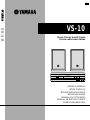
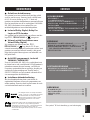
Yamaha VS-10 Manualul proprietarului
- Categorie
- Receptoare AV
- Tip
- Manualul proprietarului
Acest manual este potrivit și pentru

OWNER’S MANUAL
MODE D’EMPLOI
BEDIENUNGSANLEITUNG
BRUKSANVISNING
MANUALE DI ISTRUZIONI
MANUAL DE INSTRUCCIONES
GEBRUIKSAANWIJZING
VS-10
Home Theater Sound System
Systèm audio home cinéma
VS-10
G B
POWER
STANDBY
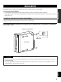
NATURAL SOUND HOME THEATER SYSTEM VS-10
OPEN
DIGITAL
DIGITAL
DOLBY
SURROUND

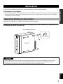
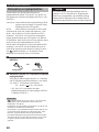
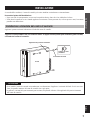
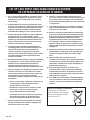
CAUTION
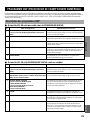
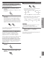
CAUTION: READ THIS BEFORE OPERATING YOUR UNIT.
1 To assure the finest performance, please read this
manual carefully. Keep it in a safe place for future
reference.
2 Install this unit in a well ventilated, cool, dry, and
clean place with at least 10 cm above, behind and on
the both sides of this unit - away from direct sunlight,
heat sources, vibration, dust, moisture, and/or cold.
3 Position this unit away from other electrical
appliances, motors and transformers to avoid
humming sounds, do not place this unit where it may
get exposed to rain or any kind of liquid to prevent
fire or electrical shock.
4 Avoid extreme temperature swings or excessive use
of humidifier in the room where this unit is installed
to prevent condensation inside this unit, which may
cause an electrical shock, fire damage to this unit,
and/or personal injury.
5 Do not cover this unit with a newspaper, a tablecloth,
a curtain, etc. in order not to obstruct heat radiation.
If the temperature inside this unit rises, it may cause
fire, damage to this unit and/or personal injury.
6 Avoid installing this unit in a place where foreign
objects and liquid might fall. It might cause a fire,
damage to this unit and/or personal injury. Do not
place the following objects on this unit:
• Other components, as they may cause damage
and/or discoloration on the surface of this unit.
• Burning objects (i.e., candles), as they may cause
fire, damage to this unit and/or personal injury.
• Containers with liquid in them, as they may cause
an electrical shock to the user and/or damage to
this unit.
7 Do not operate this unit upside-down. It may
overheat, possibly causing damage.
8 When moving this unit, be sure to first disconnect the
power cord from the AC outlet and disconnect all
cords connecting this unit to other equipment.
9 Do not use force on switches, controls or connection
cables. Never pull the cables when disconnecting
them.
10 Only voltage specified on this unit must be used.
Using this unit with a higher voltage than specified is
dangerous and may result in fire or other accidents.
YAMAHA will not be held responsible for any damage
resulting from the use of this unit with a voltage other
than that specified.
11 Do not attempt to clean this unit with chemical
solvents; this might damage the finish. Use a clean,
dry cloth.
12 Disconnect the power cord from the wall outlet when
not planning to use this unit for a long period of time,
or during an electrical storm, as they may cause
damage by lightning.
13 Do not attempt to modify or fix this unit. Contact the
qualified YAMAHA service personnel when any
service is needed. Cabinet should never be opened
for any reasons.
14 Be sure to read ‘TROUBLESHOOTING’ section
regarding common operating errors before
concluding that this unit is faulty.
■ For U.K. customers
If the socket outlets in the home are not suitable for the plug
supplied with this appliance, it should be cut off and an
appropriate 3 pin plug fitted. For details, refer to the
instructions described below.
Note
• The plug severed from the mains lead must be destroyed, as a
plug with bared flexible cord is hazardous if engaged in a live
socket outlet.
■ Special Instructions for U.K. Model
IMPORTANT
THE WIRES IN MAINS LEAD ARE COLOURED IN
ACCORDANCE WITH THE FOLLOWING CODE:
Blue: NEUTRAL
Brown: LIVE
As the colours of the wires in the mains lead of this
apparatus may not correspond with the coloured
markings identifying the terminals in your plug, proceed
as follows:
The wire which is coloured BLUE must be connected to
the terminal which is marked with the letter N or
coloured BLACK. The wire which is coloured BROWN
must be connected to the terminal which is marked with
the letter L or coloured RED.
Making sure that neither core is connected to the earth
terminal of the three pin plug.
FOR CANADIAN CUSTOMERS
To prevent electric shock, match wide blade of plug to
wide slot and fully insert.
This Class B digital apparatus complies with Canadian
ICES-003.

1
English
PREPARATION
REMOTE CONTROL
APPENDIX
PREPARATION
OPERATION
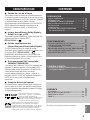
FEATURES
● Home Theater Sound
This system delivers a realistic and powerful sound
experience like that found in a movie theater just by
connecting the VS-10 to the TV. You can also enjoy
stronger bass and surround effects by adding the
separately available YAMAHA NX-SW10, consisting
of a subwoofer, a center speaker and two rear
speakers.
● Includes Dolby Digital, Dolby Pro
Logic and DTS Decoders
This system can reproduce the sound field of the
software with the g, s or
logo mark.
● Virtual Surround (available for Virtual
Dolby Digital)
The VS-10 can produce a virtual surround sound field
when playing software with the g,
s or logo mark so that you can
enjoy surround effects that give a motion to sound and
make you feel like you are in action.
● Eight DSP programs including
YAMAHA CINEMA DSP
Connecting the YAMAHA NX-SW10 (sold
separately) allows eight different DSP programs to be
used to enhance the power and realism of various
sources, from movies to concerts, sporting events and
games. Moreover, the SILENT CINEMA program
allows you to enjoy Virtual Surround by connecting
the headphones.
● Preset Remote Control
The remote control can be used to control not only the
control center, but component from other
manufacturers merely by setting the proper
manufacturer code.
PREPARATION
Manufactured under license from Dolby
Laboratories. “Dolby”, “Pro Logic” and the
double-D symbol are trademarks of Dolby
Laboratories. Confidential Unpublished Works.
©1992 – 1997 Dolby Laboratories, Inc. All rights
reserved.
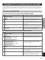
CONTENTS
y indicates a tip for your operation.
APPENDIX
GLOSSARY................................................................ 31
TROUBLESHOOTING ............................................ 32
SPECIFICATIONS.................................................... 33
INDEX ........................................................................ 34
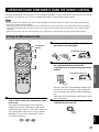
REMOTE CONTROL
OPERATING OTHER COMPONENTS USING
THE REMOTE CONTROL .................................. 27
OPERATION
OPERATING THE UNIT ......................................... 17
USING CONVENIENT FUNCTIONS .................... 19
DSP PROGRAM (DIGITAL SOUND FIELD
PROCESSOR EFFECT)........................................ 21
MENU FUNCTIONS................................................. 24
PREPARATION
FEATURES .................................................................. 1
GETTING STARTED ................................................. 2
NAMES OF ALL PARTS ............................................ 4
SPEAKER PLACEMENT .......................................... 6
INSTALLATION ......................................................... 7
CONNECTIONS.......................................................... 9
ADJUSTING THE SPEAKER
OUTPUT LEVELS ................................................. 15
Manufactured under license from Digital Theater
Systems, Inc. US Pat. No. 5,451,942 and other world-
wide patents issued and pending. “DTS”, “DTS Digital
Surround”, are trademarks of Digital Theater Systems,
Inc. Copyright 1996 Digital Theater Systems, Inc. All
Rights Reserved.

2
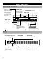
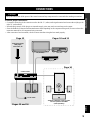
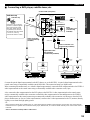
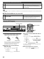
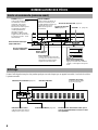
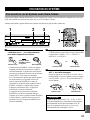
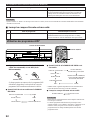
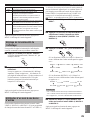
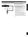
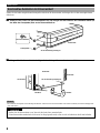
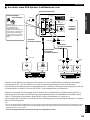
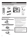
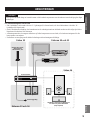
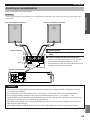
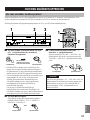
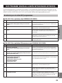
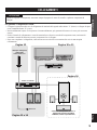
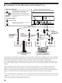
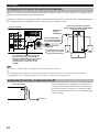
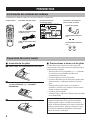
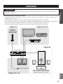
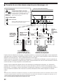
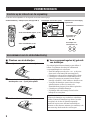
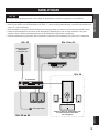
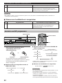
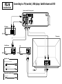
Connecting to a TV (monitor), DVD player, Satellite tuner and VCR
TV (monitor)
VIDEO
OUT
AUDIO
OUT
L
R
DVD player
VIDEO
OUT
OPTICAL DIGITAL
OUTPUT
Satellite tuner
VIDEO
OUT
AUDIO
OUT
L
R
VCR
Control center VS-10 (rear panel)
VIDEO
IN
AUDIO
IN
L
AUDIO
OUT
R
1
2
Audio connection cord (2 pin) (x 1)
Supplied cords
Commercially available cable
Optical fiber cable
Video connection cord (x 1)
R
L
V
R
L
V
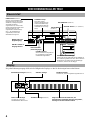
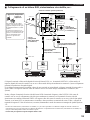
Connection Guide
DIGITAL 1
(V/PCM)
VIDEO 1 TV
VIDEO SIGNAL
INPUT
MAIN SPEAKERS
SUBWOOFER
OUT
MONITOR
OUT
SYSTEM
CONNECTOR
MARK
DO NOT CONNECT THIS UNIT TO
SPEAKERS OTHER THAN NX-VS10M
+
+
–
V RL
V RL
V RL
VV R L
V
V
V
R L
R L
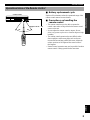
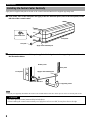
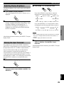
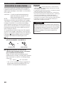
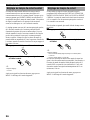
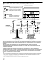
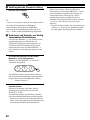
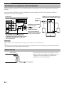
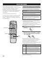
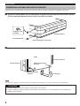
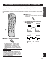
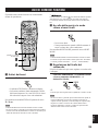
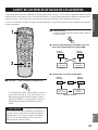
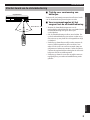
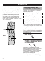
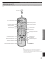
■ Inserting the batteries
1 Remove the battery compartment cover.
2 Insert the four batteries (AAA, R03, UM-4 type)
with + and – oriented properly.
3 Close the battery compartment cover.
■ Precautions regarding batteries
Misuse of dry cell batteries may result in leakage or
bursting. Be sure to follow the precautions given below.
• Insert batteries with (+) and (–) oriented according to the
marking in the battery compartment.
• Do not mix old and new batteries.
• Do not mix different types of batteries as they may offer
different voltage and performance even though they have
the same shape.
• Remove all batteries when they can no longer be used or
when the remote control will not be used for an extended
period.
• Do not use rechargeable batteries.
• If leakage occurs, wipe away all battery fluid inside the
compartment.
Preserving the manufacturer code
Replace batteries early before they become unusable.
The manufacturer code set by the user will be preserved
for about two minutes when batteries run out or when
they are removed. Note that the manufacturer code
setting may be lost if more than two minutes elapses.
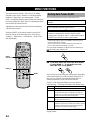
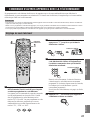
Readying the Remote Control
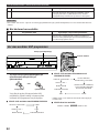
Connection guide
Audio connection cord
(2 pin, 1.5 m)
Batteries (AAA, R03, UM-4 type)Remote control
GETTING STARTED
Checking the Package Contents
Check that the following accessories are included in the package.
Video connection cord (1.5 m)
Installation attachments
for the control center
EFFECT
DSP
SET
INPUT
TEST
SUBWOOFER
+
SUBWOOFER
–
NIGHT MODE
231
564
8
MENU
97
0
+–
C/P
-
/
--
–
VOL VOL
+
P
VS10 TV VCR SAT
ON/OFF
P
MEMORY
Supporting stand
Bottom pads (x 4)
Side pads (x 2)

3
English
PREPARATION
POWER
STANDBY
NATURAL SOUND HOME THEATER SYSTEM VS-10
OPEN
DIGITAL
DIGITAL
DOLBY
SURROUND
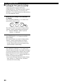
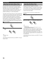
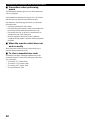
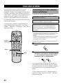
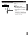
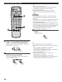
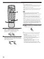
■ Battery replacement cycle
Replace all four batteries when the operational range of the
remote control starts to become shorter.
■ Precautions on handling the
remote control
• The remote control may not be able to operate the
control center when an object blocks the remote control
sensor on the unit.
• Do not subject the remote control to impact. Do not
allow it to get wet or place it in a location subject to high
humidity.
• The remote control operations become difficult when
direct sunlight or other strong light (such as from an
inverter fluorescent lamp) strikes the sensor. Adjust the
relative positions of the light and the control center if
this happens.
• Remote control operations may not be possible if another
remote control is being operated at the same time.
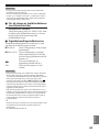
30°30°
Approx. 20 cm – 6 m
Control center
Operational Area of the Remote Control
GETTING STARTED

4
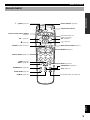
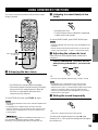
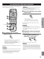
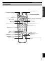
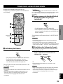
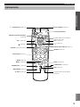
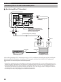
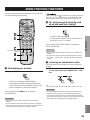
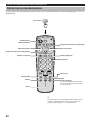
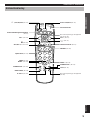
NAMES OF ALL PARTS
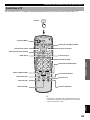
Control Center (Front Panel)
POWER
STANDBY
PHONES
INPUT
SILENT
DIGITAL2 VIDEO2
DSP VOLUME
POWER
NATURAL SOUND HOME TH
E
OPEN
DSP selector button (page 22)
VOLUME N/B (page 17)
INPUT selector
button (page 17)
STANDBY indicator
When this indicator lights up,
this unit consumes a very
small quantity of power to
receive infrared-signals from
the remote control.
VIDEO 2 audio input
terminals
DIGITAL 2 optical
digital input terminal
PHONES jack
Used to connect the headphones.
No sound can be heard from the
speakers when the headphones are
connected.
POWER (page 17)
Turns the power of the control
center on and off. This button
also turns off the subwoofer’s
power when the YAMAHA NX-
SW10 (sold separately) is
connected. The STANDBY
indicator lights when power is
turned off using p on the
remote control.
Processing indicators (page 23) VIRTUAL indicator Phones indicator
Lights when the headphones are connected.
EFFECT OFF indicator
Lights when the sound field
effects is not turned on.
TRUBASS indicator (page 19)
Shows the various information such as DSP
program name, level or operational status
To open the front door
Press downward “OPEN” on the left
bottom of the front door. When the
parts inside the front door are not used,
put the front door back.
Display
As the display becomes brighter for a few seconds each time this unit is operated, you can check the current operation clearly.
DIGITAL 2 / VIDEO 2
video input terminal

5
English
PREPARATION
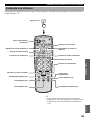
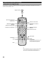
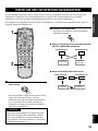
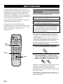
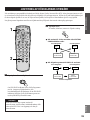
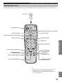
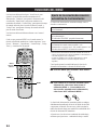
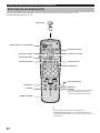
Remote Control
Not used with this unit. (page 30)
TEST (page 15)
SUBWOOFER + (page 19)
MENU + (page 24)
Numeric buttons (page 27)
INPUT selector button (page 17)
c
(page 27)
VOL + (page 17)
Not used with this unit.
(pages 29 and 30)
Transmission indicator
EFFECT ON/OFF (page 23)
t (page 19)
NIGHT MODE (page 19)
SUBWOOFER – (page 19)
MENU – (page 24)
MENU (page 24)
SET/DSP (pages 22 and 27)
m
(page 19)
VOL – (page 17)
Remote control selector buttons
(page 27)
p
(power) (page 17)
EFFECT
DSP
SET
INPUT
TEST
SUBWOOFER
+
SUBWOOFER
–
NIGHT MODE
231
564
8
MENU
97
0
+–
C/P-/--
–
VOL VOL
+
P
VS10 TV VCR SAT
ON/OFF
P
MEMORY
MEMORY (page 20)
NAMES OF ALL PARTS

6
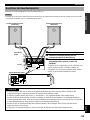
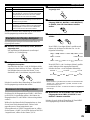
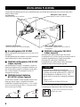
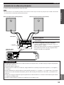
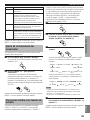
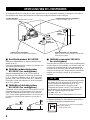
■ Main speakers NX-VS10M
Place the main speakers an equal distance from each side of
the TV monitor.
Placing the main speakers at almost the same height as your
listening position is more effective.
■ YAMAHA center speaker
NX-VS10C (sold separately)
Place the center speaker on top of the television and align
the front surface of the speaker with the front surface of the
television monitor. If the speaker cannot be placed on top of
the television, place it on a rack beneath the television as
close to the television monitor as possible.
■ YAMAHA rear speakers NX-VS10E
(sold separately)
Depending on room conditions, it is possible to place
YAMAHA rear speakers NX-VS10E on shelves or hang
them on the wall. Speakers should be placed about 1.5 m
above the floor when you sit on the floor, or about 1.8 m
above the floor when you sit on the chair.
■ YAMAHA subwoofer SW-VS10
(sold separately)
Place the subwoofer at the outside of the either right or left
main speaker and turn it slightly toward the center of the
room to reduce the wall reflections. Try altering the position
of the subwoofer versus the listening position as the relative
position will affect the way the bass sounds.
CAUTION
Although these main speakers are magnetically shielded,
they may still affect the color on the television monitor
when using the speakers near the television. Adjust the
relative positions of the speakers and the television if this
happen. Perform the following steps if you are using a
magnetically shielded television.
1 Turn off the television.
2 Wait awhile and turn the television back on.
You can also use the screw holes on the bottom of the main
speakers for installing the speakers on commercially
available speaker stands.
SPEAKER PLACEMENT
Although speakers should ideally be placed as shown below, satisfactory effects may be obtained even if you do not strictly
follow these guidelines.
1.5 - 1.8 m
Right rear
speaker
Rear speakers (sold separately)
Place behind or to the sides of the listening position.
Left rear
speaker
Subwoofer (sold separately)
Place near the right or left main speaker.
Center speaker (sold separately)
Place above the TV monitor in the center.
Main speakers
Place in each side of the TV monitor.
About 1.8 mAbout 1.5 m
When sitting on the floor. When sitting on the chair.
60 mm
A screw with a diameter of 4 mm can be used.
(Hole depth: 8 mm)

7
English
PREPARATION
INSTALLATION
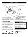
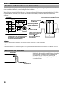
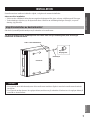
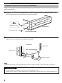
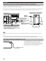
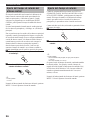
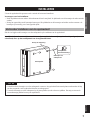
Depending on room conditions, the control center can be installed vertically or horizontally.
Precautions before installation
• Do not touch the adhesive surface after peeling off the pad as this will weaken its adhesive strength.
• Thoroughly wipe clean the surface where the pad is to be applied. Note that adhesive strength is weakened if the surface is
dusty, oily or wet.
Installing the Control Center Horizontally
Apply the four supplied bottom pads to the bottom of the control center.
Peel off the seals of the bottom pads and apply to the four indented parts (screwed parts) on the bottom
of the control center.
CAUTIONS
• Be sure to use the bottom pads when installing the control center horizontally. Otherwise, the front door of the control
center cannot open.
• Be sure to apply the bottom pads to the indented parts (screwed parts) on the bottom panel. Do not apply them to the
indented parts on the top of the control center.
Bottom panel
Bottom pad
Peel off the seal.
Apply to the indented part.

8
Note
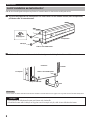
• Using only the supporting stand makes the control center unstable and the front door cannot open. Be sure to use the side pads as well.
CAUTIONS
• Be sure to place the control center with the left side down.
• When installing the control center vertically on a high place such as on a shelf, do not place close to the edge.
Installing the Control Center Vertically
Apply the two supplied side pads to the side of the control center and attach to the supplied supporting stand.
1 Peel off the seals of the side pads and apply to the two indented parts (near to the front panel) on the
left side of the control center.
2 Attach the control center with the pads applied side facing down to the supporting stand as shown in
the illustration below.
A supporting stand
Lift in this direction.
Front panel
Apply to the indented part.
Bottom panel
Rear panel
Apply to the indented part.
Side pad
Peel off the seal.
Front panel
INSTALLATION

9
English
PREPARATION
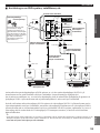
NATURAL SOUND HOME THEATER SYSTEM VS-10
DIGITAL
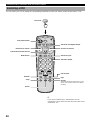
DIGITAL
DOLBY
SURROUND
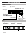
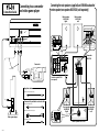
CONNECTIONS
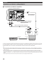
CAUTION
Always be sure to turn off the power of the control center and any component to be connected when making connections.
To ensure proper connections
• Connect the white plug of the connection cord to the left “L” (white) audio signal terminal and connect the red plug to the
right “R” (red) terminal.
• Insert the plug securely. If the plug is not inserted securely, noise may result or sound may not be output.
• Since the method of connection and terminal names differ depending on the component being used, be sure to refer to the
instruction manuals for all components being connected.
• After connections have been made, check one more time that wiring has been made properly.
Page 12
Pages 13 and 14
Page 14
Pages 10 and 11
Video game player,
DVD player,
Camcorder, etc.
TV (monitor)
VCR, etc.
DVD player, etc.
Control center
Main speakers
To AC outlet
YAMAHA subwoofer, center speaker
and rear speakers NX-SW10
(sold separately)

10
DIGITAL 1
(V/PCM)
VIDEO 1 TV
VIDEO SIGNAL
INPUT
MAIN SPEAKERS
SUBWOOFER
OUT
MONITOR
OUT
SYSTEM
CONNECTOR
MARK
DO NOT CONNECT THIS UNIT TO
SPEAKERS OTHER THAN NX-VS10M
+
–
+
–
RL
OUTPUT INPUT
AUDIO/VIDEO
IN
AUDIO/VIDEO
OUT
R L
AUDIO
IN R
VIDEO IN
VIDEO OUT
AUDIO
IN L
R
L
AUDIO
OUT R
AUDIO
OUT L
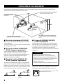
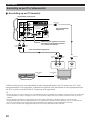
Connect the audio output terminals on the TV (monitor) to the TV audio input terminals on the control center using the
supplied audio connection cord and the video input terminal on the TV (monitor) to the MONITOR OUT terminal on the
control center using the supplied video connector cord.
y
• The sound from the TV can be heard using the speakers connected to the control center. (Although you can also hear the sound from the TV
speakers, we recommend you to reduce the TV volume so that you may enjoy the full benefit of the VS-10.)
• To monitor the picture output from the component such as a DVD player, satellite tuner, camcorder, video game player, etc. of which the
video output terminal is connected to the video input terminal on the control center (as described on pages 11 and 12), switch the video
input of the TV (monitor) connected to the MONITOR OUT terminal on the control center.
• The TV (monitor) without the audio output terminals cannot be connected to the control center.
TV (monitor)VCR, etc.
Audio connection cord (supplied)
Control center (rear panel)
Connecting a TV or VCR
■ Connecting a TV (monitor)
Video connection cord
(supplied)
CONNECTIONS
As this terminal is used for an
examination in the factory, do not
connect any equipment to this terminal.

11
English
PREPARATION
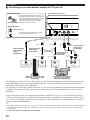
DIGITAL 1
(V/PCM)
VIDEO 1 TV
VIDEO SIGNAL
INPUT
MAIN SPEAKERS
SUBWOOFER
OUT
MONITOR
OUT
DO NOT CONNECT THIS UNIT TO
SPEAKERS OTHER THAN NX-VS10M
+
––
RL
OUTPUT
OPTICAL DIGITAL
OUTPUT
OUTPUT OUTPUT
R L
R L
VIDEO IN VIDEO IN
VIDEO OUT
AUDIO
OUT R
AUDIO
OUT L
VIDEO
OUT
AUDIO IN LAUDIO IN R
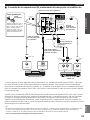
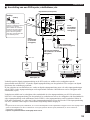
Connect the optical digital output terminal on the DVD player, etc. to the DIGITAL 1 (optical) digital input terminal on the
control center using a commercially available optical fiber cable. This connection brings you digital sound.
When connecting the satellite tuner, etc. without a digital output terminal, connect the audio output terminals to the VIDEO 1
audio input terminals on the control center using a commercially available audio connection cord (2 pin).
Also, connect the video output terminal on the DVD player to the DIGITAL 1 video input terminal on the control center
using a commercially available video connection cord and the video output terminal on the satellite tuner to the VIDEO 1
video input terminal on the control center using a commercially available video connection cord. However, when the DVD
player, satellite tuner, etc. has an S video output terminal, connect to the S video input terminal on the TV (monitor) directly
so that you can obtain the high quality picture.
y
• The sound from a DVD player, satellite tuner, etc. can be heard using the speakers connected to the control center. The sound cannot be
heard from the TV’s speakers. The sound from a DVD player, satellite tuner, etc. cannot be heard when the power of the control center is
turned off.
• The VS-10 cannot record any audio or video source.
Satellite tuner, etc.
DVD player, etc.
Control center (rear panel)
■ Connecting a DVD player, satellite tuner, etc.
Video connection
cord (commercially
available)
Video
connection cord
(commercially
available)
Audio connection cord
(commercially available)
Optical fiber cable
(EIA standard)
(commercially available)
Remove the cap covering the
DIGITAL 1 terminal (optical)
when connecting an optical
fiber cable. Safely store the
cap and always re-insert it in
the terminal when the terminal
is not in use. (This cap
prevents the entrance of dust.)
Anti-dust cap
CONNECTIONS
Anti-dust cap

12
POWER
STANDBY
PHONES
SILEN
T
DIGITAL2 VIDEO2
RL
OUTPUT
OUTPUTOUTPUT
OPTICAL DIGITAL
OUTPUT
AUDIO
OUT R
AUDIO
OUT L
R L
AUDIO
IN L
L
VIDEO OUT
VIDEO IN
VIDEO OUT
VIDEO IN AUDIO
IN R
R
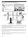
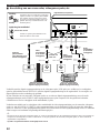
When connecting the video game player, DVD player, etc. with a optical digital output terminal, connect the optical digital
output terminal to the DIGITAL 2 (optical) digital input terminal on the control center using a commercially available optical
fiber cable. This allows you to enjoy a digital sound.
When connecting the camcorder, video game player, etc. without a digital output terminal, connect the audio output terminals
to the VIDEO 2 audio input terminals on the front panel of the control center using a commercially available audio
connection cord (2 pin).
Also, connect the video output terminal on the camcorder, video game player, etc. to the DIGITAL 2 (VIDEO 2) video input
terminal on the control center using a commercially available video connection cord. However, when the camcorder, video
game player, etc. has an S video output terminal, connect to the S video input terminal on the TV (monitor) directly so that
you can obtain the high quality picture.
y
• The sound from camcorder, video game player, etc. can be heard using the speakers connected to the control center. The sound cannot be
heard from the TV’s speakers. The sound from a camcorder, video game, etc. cannot be heard when the power of the control center is
turned off.
• The VS-10 cannot record any audio or video source.
Video game player or DVD
player, etc. which has an optical
digital output terminal
Camcorder or video game
player, etc. which has no
optical digital output terminal
Audio connection
cord (commercially
available)Optical fiber cable
(EIA standard)
(commercially
available)
Connect either.
Control center (Front panel)
■ Connecting a camcorder, video game player, etc.
Video connection
cord
(commercially
available)
Remove the cap covering the DIGITAL 2 terminal
(optical) when connecting an optical fiber cable.
Safely store the cap and always re-insert it in the
terminal when the terminal is not in use. (This cap
prevents the entrance of dust.)
Anti-dust cap
Video
connection cord
(commercially
available)
CONNECTIONS
Less than 14 mm
Use the optical fiber cable of which the plug
dimensions are less than 14 mm.
Anti-dust cap
Optical fiber cable

13
English
PREPARATION
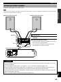
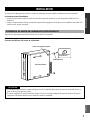
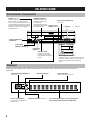
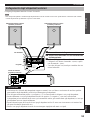
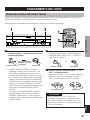
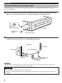
CAUTIONS
• Do not let the bare speaker wire touch each other and do not let them touch any metal part of the speakers. This could
damage the speakers.
• Do not mistakenly connect positive (+) to negative (–) or vice versa when connecting speaker cords.
• Insert the speaker cords securely so that positive (+) and negative (–) do not short. The speaker may not output any
sound or may output noise, causing damage to the speakers, if speaker cords are not inserted securely.
• Only insert the bare wire portion of the speaker cords into the holes. Sound will not be output if you insert as far as the
plastic insulation part of the cord.
• Secure the speaker cords so that they will not catch on hands or feet.
Connecting the Main Speakers
Connect the main speakers to the control center.
Note
• Do not connect any speakers to the speaker terminals on the control center except for the supplied main speakers (NX-VS10M). Damage
may result if a different speaker is connected.
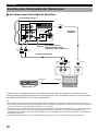
DIGITAL 1
(V/PCM)
VIDEO 1 TV
VIDEO SIGNAL
INPUT
MAIN SPEAKERS
SUBWOOFER
OUT
MONITOR
OUT
SYSTEM
CONNECTOR
MARK
DO NOT CONNECT THIS UNIT TO
SPEAKERS OTHER THAN NX-VS10M
+
–
+
–
MAINS
+
DO NOT CONNECT THIS UNIT TO
SPEAKERS OTHER THAN NX-VS10M
–
+
–
1
2
3
MAIN SPEAKERS
Right main speaker (Rear panel) Left main speaker (Rear panel)
Bare wire
Tab
Control center (Rear panel)
1 Open the tab.
2 Insert the bare wire of the speaker cord into
the hole.
3 Return the tab until it clicks.
• Connect the white cord to the + terminal (red), and the
black cord to the – terminal (black).
• Once connected, pull gently on the speaker cords to
check that they are connected securely.
CONNECTIONS

14
DIGITAL 1
(V/PCM)
VIDEO 1 TV
VIDEO SIGNAL
INPUT
MAIN SPEAKERS
SUBWOOFER
OUT
MONITOR
OUT
SYSTEM
CONNECTOR
MARK
DO NOT CONNECT THIS UNIT TO
SPEAKERS OTHER THAN NX-VS10M
+
–
+
–
MAINS
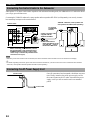
Once all connections have been made, check them one more
time. Finally, insert the plug of the power supply cord for
the control center into an AC outlet. Disconnect the power
supply cord if you will not use the unit for an extended
period.
To AC outlet
Control center
Note
• When the power of the control center is turned off, that of the YAMAHA subwoofer SW-VS10 is also turned off accordingly.
y
• For details regarding connections, please refer to the instruction manuals for your subwoofer or the owner’s manual for the YAMAHA
subwoofer, center speaker and rear speakers NX-SW10 (sold separately).
Connecting the AC Power Supply Cord
Match the mark on the
plug with the mark on
the terminal and insert.
To SYSTEM
CONNECTOR terminal
System connector cable
supplied with the
YAMAHA NX-SW10
To SYSTEM
CONNECTOR
terminal
YAMAHA subwoofer, center speaker and
rear speakers NX-SW10 (sold separately)
Control center
Connecting the Control Center to the Subwoofer
Although the VS-10 alone can be used to reproduce rich and natural sounding audio, the additional use of a subwoofer allows
you to enjoy powerful bass tones.
Connecting the YAMAHA subwoofer, center speaker and rear speakers NX-SW10 (sold separately) can not only increase
bass sensitivity but improve the surround effect.
When connecting your subwoofer, connect
the input terminal on the subwoofer to the
SUBWOOFER OUT terminal on the control
center using a commercially available audio
connection cord (1 pin).
CONNECTIONS

15
English
PREPARATION
EFFECT
DSP
SET
INPUT
TEST
SUBWOOFER
+
SUBWOOFER
–
NIGHT MODE
231
564
8
MENU
97
0
+–
C/P
-
/
--
–
VOL VOL
+
P
VS10 TV VCR SAT
ON/OFF
P
MEMORY
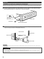
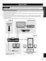
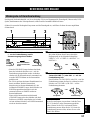
1
2
RIGHTCENTERLEFT
RIGHT
SURROUND
LEFT
SURROUND
RIGHTLEFT
RIGHT
SURROUND
LEFT
SURROUND
Rear speakers
Main
speaker
● When the NX-SW10 is connected:
(Virtual)(Virtual)
2 Press TEST.
A test tone (like pink noise) will be output in the
following order.
● When only the VS-10 is connected or the
VIRTUAL SURROUND is selected:
1 Press p to turn on the power.
If the STANDBY indicator is lit, turn on the power
using p on the remote control. If the main power is
off (when the STANDBY indicator is not lit), turn on
the power by pressing POWER on the control center.
CAUTION
When the NX-SW10 (sold separately) is connected to the
control center, insert the plug of the AC power supply
cord of the subwoofer SW-VS10 into an AC outlet
beforehand and turn on the power of the control center.
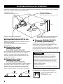
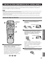
ADJUSTING THE SPEAKER OUTPUT LEVELS
When reproducing the source encoded with a Dolby Digital, Dolby Surround or DTS, it is important to adjust the sound
output level heard at the listening position to the same from each speaker. Therefore, the best performance of these digital
sound fields can be obtained. Even when the other sound field is selected, you can enjoy the characteristics of each sound
field.
Speaker output levels may be adjusted using the remote control before playback by following the steps.
Main
speaker
Main
speaker
Main
speaker

16
3 Adjust the level of the test tone using VOL +/–.
(Adjust to your listening level.)
Pressing VOL + increases the level, while pressing
VOL – decreases the level.
4 Adjust the sound output level of each speaker
while listening to the test tone.
Pressing f increases the level, while pressing w
decreases the level.
y
• When only the VS-10 is connected:
Adjust the sound output levels of the rear virtual speakers and the
main speakers so that they become almost the same.
• When the NX-SW10 is connected:
Adjust the sound output levels of the center speaker and the rear
speakers so that they become almost the same as that of the main
speakers.
Notes
• When the sound output levels of the main speakers are adjusted,
adjust the sound output levels of the center speaker, rear speakers
and rear virtual speakers again.
• The sound output levels of right and left virtual speakers cannot
be adjusted separately. While one level is adjusted, the other is
also adjusted similarly.
• When the headphones are connected, the order of each speaker
from which a test tone is heard is the same as that of VS-10 only.
However, the sound output level of main speakers cannot be
adjusted. Only the sound output level of rear speakers can be
adjusted, however, that level cannot be adjusted for each right or
left rear speaker separately. (Adjustable range: –3 to +3 dB)
5 When the adjustment is complete, press TEST.
A test tone stops.
y
The sound output level can be adjusted in the following range.
• When only the VS-10 is connected or the VIRTUAL
SURROUND is selected:
– Right and left main speakers: –10 to ±0 dB
– Rear virtual speakers: –3 to +3 dB
– The minimum level for the main speakers is –10 dB, while that
for the rear virtual speakers is –3 dB.
• When the NX-SW10 is connected:
– Right and left main speakers: –10 to ±0 dB
– Center speaker: –20 to +6 dB
– Right and left rear speakers: –20 to +6 dB
– The minimum level for the main speakers is –10 dB, while that
for the center speaker and the rear speakers is –20 dB.
EFFECT
DSP
SET
INPUT
TEST
SUBWOOFER
+
SUBWOOFER
–
NIGHT MODE
231
564
8
MENU
97
0
+–
C/P
-
/
--
–
VOL VOL
+
P
VS10 TV VCR SAT
ON/OFF
P
MEMORY
5
4
3
ADJUSTING THE SPEAKER OUTPUT LEVELS

17
English
OPERATION
• When the STANDBY indicator lights or flashes, the
power can be turned on using p on the remote
control. The power also can be turned on by pressing
the INPUT selector button on the control center.
• The VS-10 memorizes the last state when the power
is turned off. If you turn off the power using
POWER on the control center in standby mode
(when the STANDBY indicator lights), the unit
enters standby mode when you press POWER on the
control center next time.
If you turn off the power using POWER on the
control center when the power is turned on (when the
STANDBY indicator does not light), the power is
turned on when you press POWER on the control
center next time.
2 Press the INPUT selector button.
Each time the button is pressed, the input is switched in
the order: VIDEO 1 → TV → VIDEO 2 → DIGITAL 1
→ DIGITAL 2.
1 Press POWER on the control center and press
p on the remote control to turn on the power.
OPERATING THE UNIT
Enjoying the Home Theater Sound System
This section describes how to select the input source to enjoy the sound from a TV, VCR, DVD player, satellite tuner or video
game player with the VS-10 and to adjust the volume.
First turn on the power of the playback component and the TV, and then follow the steps described below.
POWER
STANDBY
PHONES
INPUT
SILENT
DIGITAL2 VIDEO2
DSP VOLUME
1
2
3
EFFECT
DSP
SET
INPUT
231
–
VOL VOL
+
P
VS10 TV VCR SAT
ON/OFF
P
MEMORY
3
1
2
When the
STANDBY indicator
lights or flashes.
CAUTION
When the “TV”, “VCR” or “SAT” button on the remote
control is pressed to control another unit, the remote
control can not control the VS-10. In this case, press the
“VS10” button on the remote control and operate the
VS-10.
OPERATION
Remote control
or
Front panel
3 Adjust the level using VOLUME B/N (or VOL
+/– on the remote control).
Pressing VOLUME B (or VOL + on the remote
control) increases the level, while pressing VOLUME
N (or VOL – on the remote control) decreases the
level.
Remote control
or
Front panel
Remote control
Front panel

18
CAUTION
The variable sound intensity range is large when playing
back a CD or MD. So, if the source that includes the
sudden change from a small sound level to large one is
played back at a maximum volume for a long time, the
speakers may be damaged.
Switching the input mode
This function allows you to switch the input mode of the
component connected to the DIGITAL 1 or DIGITAL 2
terminal to “Auto Mode” or “dts Fix”.
Auto Mode : This recognizes the PCM signal such as a CD,
Dolby digital signal or DTS signal
automatically.
dts Fix : This fixes to a DTS signal.
Normally, the playback can be performed with the “Auto
Mode”. If you play a CD encoded with DTS in the “Auto
Mode” setting, there will be a short noise at first while the
unit recognizes the DTS signal and turns on the DTS
decoder. This is not a malfunction and can be avoided by
setting the input mode to “dts Fix” beforehand. When you
play and stop a CD encoded with DTS in the “Auto Mode”
setting, the sound is muted even if you play the PCM signal
such as a normal CD and the
indicator flashes for about
30 seconds. However, this condition is released after about
30 seconds.
1 Press the INPUT selector button to select
DIGITAL 1 or DIGITAL 2.
2 Press the INPUT selector button again for
about 3 seconds to switch the input mode.
Each time the button is pressed for about 3 seconds, the
input mode is switched between “Auto Mode” and “dts
Fix”, and displayed as follows.
“D1$ dts Fix” “D1$Auto Mode”
•“D1” or “D2” is displayed before the selected input
mode when DIGITAL 1 or DIGITAL 2 is selected
respectively.
Notes
• The indicator lights when “dts Fix” is selected, and goes off
when a digital signal encoded with DTS is not input in the “Auto
Mode” setting.
• The setting of the input mode returns to “Auto mode” when the
power of the control center is turned off.
• When playing a source encoded with DTS, be sure to connect the
player to the DIGITAL 1 or DIGITAL 2 input terminal of the
control center with an optical fiber cable.
• If the digital output data of the player has been processed in any
way, you may not be able to perform DTS decoding even if you
make a digital connection between this unit and the player.
Remote control
or
Front panel
OPERATING THE UNIT
Pagina se încarcă ...
Pagina se încarcă ...
Pagina se încarcă ...
Pagina se încarcă ...
Pagina se încarcă ...
Pagina se încarcă ...
Pagina se încarcă ...
Pagina se încarcă ...
Pagina se încarcă ...
Pagina se încarcă ...
Pagina se încarcă ...
Pagina se încarcă ...
Pagina se încarcă ...
Pagina se încarcă ...
Pagina se încarcă ...
Pagina se încarcă ...
Pagina se încarcă ...
Pagina se încarcă ...
Pagina se încarcă ...
Pagina se încarcă ...
Pagina se încarcă ...
Pagina se încarcă ...
Pagina se încarcă ...
Pagina se încarcă ...
Pagina se încarcă ...
Pagina se încarcă ...
Pagina se încarcă ...
Pagina se încarcă ...
Pagina se încarcă ...
Pagina se încarcă ...
Pagina se încarcă ...
Pagina se încarcă ...
Pagina se încarcă ...
Pagina se încarcă ...
Pagina se încarcă ...
Pagina se încarcă ...
Pagina se încarcă ...
Pagina se încarcă ...
Pagina se încarcă ...
Pagina se încarcă ...
Pagina se încarcă ...
Pagina se încarcă ...
Pagina se încarcă ...
Pagina se încarcă ...
Pagina se încarcă ...
Pagina se încarcă ...
Pagina se încarcă ...
Pagina se încarcă ...
Pagina se încarcă ...
Pagina se încarcă ...
Pagina se încarcă ...
Pagina se încarcă ...
Pagina se încarcă ...
Pagina se încarcă ...
Pagina se încarcă ...
Pagina se încarcă ...
Pagina se încarcă ...
Pagina se încarcă ...
Pagina se încarcă ...
Pagina se încarcă ...
Pagina se încarcă ...
Pagina se încarcă ...
Pagina se încarcă ...
Pagina se încarcă ...
Pagina se încarcă ...
Pagina se încarcă ...
Pagina se încarcă ...
Pagina se încarcă ...
Pagina se încarcă ...
Pagina se încarcă ...
Pagina se încarcă ...
Pagina se încarcă ...
Pagina se încarcă ...
Pagina se încarcă ...
Pagina se încarcă ...
Pagina se încarcă ...
Pagina se încarcă ...
Pagina se încarcă ...
Pagina se încarcă ...
Pagina se încarcă ...
Pagina se încarcă ...
Pagina se încarcă ...
Pagina se încarcă ...
Pagina se încarcă ...
Pagina se încarcă ...
Pagina se încarcă ...
Pagina se încarcă ...
Pagina se încarcă ...
Pagina se încarcă ...
Pagina se încarcă ...
Pagina se încarcă ...
Pagina se încarcă ...
Pagina se încarcă ...
Pagina se încarcă ...
Pagina se încarcă ...
Pagina se încarcă ...
Pagina se încarcă ...
Pagina se încarcă ...
Pagina se încarcă ...
Pagina se încarcă ...
Pagina se încarcă ...
Pagina se încarcă ...
Pagina se încarcă ...
Pagina se încarcă ...
Pagina se încarcă ...
Pagina se încarcă ...
Pagina se încarcă ...
Pagina se încarcă ...
Pagina se încarcă ...
Pagina se încarcă ...
Pagina se încarcă ...
Pagina se încarcă ...
Pagina se încarcă ...
Pagina se încarcă ...
Pagina se încarcă ...
Pagina se încarcă ...
Pagina se încarcă ...
Pagina se încarcă ...
Pagina se încarcă ...
Pagina se încarcă ...
Pagina se încarcă ...
Pagina se încarcă ...
Pagina se încarcă ...
Pagina se încarcă ...
Pagina se încarcă ...
Pagina se încarcă ...
Pagina se încarcă ...
Pagina se încarcă ...
Pagina se încarcă ...
Pagina se încarcă ...
Pagina se încarcă ...
Pagina se încarcă ...
Pagina se încarcă ...
Pagina se încarcă ...
Pagina se încarcă ...
Pagina se încarcă ...
Pagina se încarcă ...
Pagina se încarcă ...
Pagina se încarcă ...
Pagina se încarcă ...
Pagina se încarcă ...
Pagina se încarcă ...
Pagina se încarcă ...
Pagina se încarcă ...
Pagina se încarcă ...
Pagina se încarcă ...
Pagina se încarcă ...
Pagina se încarcă ...
Pagina se încarcă ...
Pagina se încarcă ...
Pagina se încarcă ...
Pagina se încarcă ...
Pagina se încarcă ...
Pagina se încarcă ...
Pagina se încarcă ...
Pagina se încarcă ...
Pagina se încarcă ...
Pagina se încarcă ...
Pagina se încarcă ...
Pagina se încarcă ...
Pagina se încarcă ...
Pagina se încarcă ...
Pagina se încarcă ...
Pagina se încarcă ...
Pagina se încarcă ...
Pagina se încarcă ...
Pagina se încarcă ...
Pagina se încarcă ...
Pagina se încarcă ...
Pagina se încarcă ...
Pagina se încarcă ...
Pagina se încarcă ...
Pagina se încarcă ...
Pagina se încarcă ...
Pagina se încarcă ...
Pagina se încarcă ...
Pagina se încarcă ...
Pagina se încarcă ...
Pagina se încarcă ...
Pagina se încarcă ...
Pagina se încarcă ...
Pagina se încarcă ...
Pagina se încarcă ...
Pagina se încarcă ...
Pagina se încarcă ...
Pagina se încarcă ...
Pagina se încarcă ...
Pagina se încarcă ...
Pagina se încarcă ...
Pagina se încarcă ...
Pagina se încarcă ...
Pagina se încarcă ...
Pagina se încarcă ...
Pagina se încarcă ...
Pagina se încarcă ...
Pagina se încarcă ...
Pagina se încarcă ...
Pagina se încarcă ...
Pagina se încarcă ...
Pagina se încarcă ...
Pagina se încarcă ...
Pagina se încarcă ...
Pagina se încarcă ...
Pagina se încarcă ...
Pagina se încarcă ...
Pagina se încarcă ...
Pagina se încarcă ...
Pagina se încarcă ...
Pagina se încarcă ...
Pagina se încarcă ...
Pagina se încarcă ...
Pagina se încarcă ...
Pagina se încarcă ...
Pagina se încarcă ...
Pagina se încarcă ...
Pagina se încarcă ...
Pagina se încarcă ...
Pagina se încarcă ...
Pagina se încarcă ...
Pagina se încarcă ...
Pagina se încarcă ...
Pagina se încarcă ...
Pagina se încarcă ...
Pagina se încarcă ...
Pagina se încarcă ...
Pagina se încarcă ...
Pagina se încarcă ...
Pagina se încarcă ...
Pagina se încarcă ...
Pagina se încarcă ...
Pagina se încarcă ...
Pagina se încarcă ...
Pagina se încarcă ...
Pagina se încarcă ...
Pagina se încarcă ...
-
 1
1
-
 2
2
-
 3
3
-
 4
4
-
 5
5
-
 6
6
-
 7
7
-
 8
8
-
 9
9
-
 10
10
-
 11
11
-
 12
12
-
 13
13
-
 14
14
-
 15
15
-
 16
16
-
 17
17
-
 18
18
-
 19
19
-
 20
20
-
 21
21
-
 22
22
-
 23
23
-
 24
24
-
 25
25
-
 26
26
-
 27
27
-
 28
28
-
 29
29
-
 30
30
-
 31
31
-
 32
32
-
 33
33
-
 34
34
-
 35
35
-
 36
36
-
 37
37
-
 38
38
-
 39
39
-
 40
40
-
 41
41
-
 42
42
-
 43
43
-
 44
44
-
 45
45
-
 46
46
-
 47
47
-
 48
48
-
 49
49
-
 50
50
-
 51
51
-
 52
52
-
 53
53
-
 54
54
-
 55
55
-
 56
56
-
 57
57
-
 58
58
-
 59
59
-
 60
60
-
 61
61
-
 62
62
-
 63
63
-
 64
64
-
 65
65
-
 66
66
-
 67
67
-
 68
68
-
 69
69
-
 70
70
-
 71
71
-
 72
72
-
 73
73
-
 74
74
-
 75
75
-
 76
76
-
 77
77
-
 78
78
-
 79
79
-
 80
80
-
 81
81
-
 82
82
-
 83
83
-
 84
84
-
 85
85
-
 86
86
-
 87
87
-
 88
88
-
 89
89
-
 90
90
-
 91
91
-
 92
92
-
 93
93
-
 94
94
-
 95
95
-
 96
96
-
 97
97
-
 98
98
-
 99
99
-
 100
100
-
 101
101
-
 102
102
-
 103
103
-
 104
104
-
 105
105
-
 106
106
-
 107
107
-
 108
108
-
 109
109
-
 110
110
-
 111
111
-
 112
112
-
 113
113
-
 114
114
-
 115
115
-
 116
116
-
 117
117
-
 118
118
-
 119
119
-
 120
120
-
 121
121
-
 122
122
-
 123
123
-
 124
124
-
 125
125
-
 126
126
-
 127
127
-
 128
128
-
 129
129
-
 130
130
-
 131
131
-
 132
132
-
 133
133
-
 134
134
-
 135
135
-
 136
136
-
 137
137
-
 138
138
-
 139
139
-
 140
140
-
 141
141
-
 142
142
-
 143
143
-
 144
144
-
 145
145
-
 146
146
-
 147
147
-
 148
148
-
 149
149
-
 150
150
-
 151
151
-
 152
152
-
 153
153
-
 154
154
-
 155
155
-
 156
156
-
 157
157
-
 158
158
-
 159
159
-
 160
160
-
 161
161
-
 162
162
-
 163
163
-
 164
164
-
 165
165
-
 166
166
-
 167
167
-
 168
168
-
 169
169
-
 170
170
-
 171
171
-
 172
172
-
 173
173
-
 174
174
-
 175
175
-
 176
176
-
 177
177
-
 178
178
-
 179
179
-
 180
180
-
 181
181
-
 182
182
-
 183
183
-
 184
184
-
 185
185
-
 186
186
-
 187
187
-
 188
188
-
 189
189
-
 190
190
-
 191
191
-
 192
192
-
 193
193
-
 194
194
-
 195
195
-
 196
196
-
 197
197
-
 198
198
-
 199
199
-
 200
200
-
 201
201
-
 202
202
-
 203
203
-
 204
204
-
 205
205
-
 206
206
-
 207
207
-
 208
208
-
 209
209
-
 210
210
-
 211
211
-
 212
212
-
 213
213
-
 214
214
-
 215
215
-
 216
216
-
 217
217
-
 218
218
-
 219
219
-
 220
220
-
 221
221
-
 222
222
-
 223
223
-
 224
224
-
 225
225
-
 226
226
-
 227
227
-
 228
228
-
 229
229
-
 230
230
-
 231
231
-
 232
232
-
 233
233
-
 234
234
-
 235
235
-
 236
236
-
 237
237
-
 238
238
-
 239
239
-
 240
240
-
 241
241
-
 242
242
-
 243
243
-
 244
244
-
 245
245
-
 246
246
-
 247
247
-
 248
248
-
 249
249
-
 250
250
-
 251
251
-
 252
252
-
 253
253
-
 254
254
-
 255
255


Yamaha VS-10 Manualul proprietarului
- Categorie
- Receptoare AV
- Tip
- Manualul proprietarului
- Acest manual este potrivit și pentru
în alte limbi
- Türkçe: Yamaha VS-10 El kitabı
- français: Yamaha VS-10 Le manuel du propriétaire
- English: Yamaha VS-10 Owner's manual
- Deutsch: Yamaha VS-10 Bedienungsanleitung
- italiano: Yamaha VS-10 Manuale del proprietario
- español: Yamaha VS-10 El manual del propietario
- svenska: Yamaha VS-10 Bruksanvisning
- dansk: Yamaha VS-10 Brugervejledning
- Nederlands: Yamaha VS-10 de handleiding
Lucrări conexe
-
Yamaha VS-10 Manual de utilizare
-
-
-
-
Yamaha DSP-A1 Manual de utilizare
-
-
-
-
-
Yamaha MSP7 STUDIO Manualul proprietarului