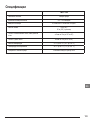
Stanley FMHT77598 Manual de utilizare
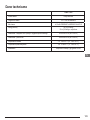
- Categorie
- Nivelurile laserului
- Tip
- Manual de utilizare
Acest manual este potrivit și pentru

FMHT77598
Self-Leveling 5-Dot Cross Line Laser
E
GB
NL
GR
I
FIN
HU
BG
LV
D
DK
CZ
ES
NO
SK
RO
LT
F
SE
RU
PT
PL
SI
EE
TR
HR
www.2helpU.com
Please read these instructions before operating the product.

8
A
1
3
x5
x1
x2
x3
x4
< 5%
> 5%
=
=
=
=
=
=
2
6
7
4
5
Figures
2

B
C
1/4-20
5/8-11
3

Figures
4
D
P1
xx
P2
P3
xx
P2
P1
x
30’ (9m)
>
2
1
E

5
D
1
P
1
P
1
D
½
D
½
D
1
P
1
D
½
D
½
P
2
P
2
30’ (9m)
>
F G
H
1
2
3
P3
D1
D1
2 x D1
P2
P1
P4
P4
P1
2 x D1
D1
P1
P2
D1
P3
P1
P2
P3
P1
P2
x
x
x
x
x
20’ (6m)
>
1
2
3
1
2

Figures
6
4
I
J
P2
P2 P3
P1
P1
x
x
x
x
x
1
2
1
2
3
P1
P2
P3
D1
P1
P2
P5
P4
P3
P1
P6
P2
P5
P4
P3
P7
P1
P6
P2
P5
P4
P3
K

7
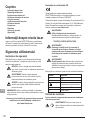
GB
Contents
• Laser Information
• User Safety
• Charging the Battery
• Turning the Laser On
• Using the Mounting Block
• Checking Laser Accuracy
• Using the Laser
• Maintenance
• Troubleshooting
• Service and Repairs
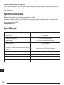
• Specications
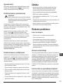
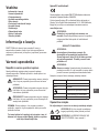
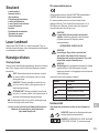
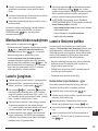
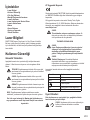
Laser Information
The FMHT77598 laser is a Class 2 laser product. The laser is a
self-leveling laser tool that can be used for horizontal (level) and
vertical (plumb) alignment projects.
User Safety
Safety Guidelines
The denitions below describe the level of severity for each
signal word. Please read the manual and pay attention to these
symbols.
DANGER: Indicates an imminently hazardous
situation which, if not avoided, will result in death or
serious injury.
WARNING: Indicates a potentially hazardous
situation which, if not avoided, could result in death or
serious injury.
CAUTION: Indicates a potentially hazardous situation
which, if not avoided, may result in minor or moderate
injury.
NOTICE: Indicates a practice not related to personal injury
which, if not avoided, may result in property damage.
If you have any questions or comments about this or any
Stanley tool, go to http://www.2helpU.com.
EC-Declaration of Conformity
Stanley herewith declares that the product FMHT77598 is in
compliance with the essential requirements and all other provisions
of Directive 1999/5/EC.
The full text of the EU Declaration of Conformity can be
requested at Stanley Tools, Egide Walschaertsstraat 14-16,
2800 Mechelen, Belgium or is available at the following internet
address: www.2helpu.com.
WARNING:
Read and understand all instructions. Failure to
follow the warnings and instructions in this manual
may result in serious personal injury.
SAVE THESE INSTRUCTIONS
WARNING:
Laser Radiation Exposure. Do not disassemble
or modify the laser level. There are no user
serviceable parts inside. Serious eye injury could
result.
WARNING:
Hazardous Radiation. Use of controls or
adjustments, or performance of procedures, other
than those specied herein may result in hazardous
radiation exposure.
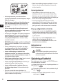
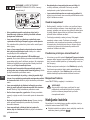
The label on your laser may include the following symbols.
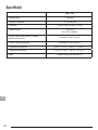
Symbol Meaning
V Volts
mW Milliwatts
Laser Warning
nm Wavelength in nanometers
2 Class 2 Laser
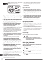
Warning Labels
For your convenience and safety, the following labels are
on your laser.
WARNING: To reduce the risk of injury, user
must read instruction manual.
WARNING: LASER RADIATION. DO NOT
STARE INTO BEAM. Class 2 Laser Product.

8
GB
7.2V DC 2.0Ah 14.4Wh
FMHT77598 www.STANLEYTOOLS.com
Li-ion
2INR19/66
5002595
EU
Use only with
charger listed
in Operator’s
Manual
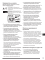
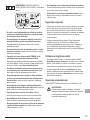
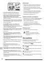
• If the equipment is used in a manner not specied by the
manufacturer, the protection provided by the equipment
may be impaired.
• Do not operate the laser in explosive atmospheres,
such as in the presence of ammable liquids, gases,
or dust. This tool may create sparks which may ignite the
dust or fumes.
• Store an idle laser out of reach of children and other
untrained persons. Lasers are dangerous in the hands of
untrained users.
• Tool service MUST be performed by qualied repair
personnel. Service or maintenance performed by unqualied
personnel may result in injury. To locate your nearest Stanley
service center go to http://www.2helpU.com.
• Do not use optical tools such as a telescope or transit to
view the laser beam. Serious eye injury could result.
• Do not place the laser in a position which may cause
anyone to intentionally or unintentionally stare into the
laser beam. Serious eye injury could result.
• Do not position the laser near a reective surface which
may reect the laser beam toward anyone’s eyes. Serious
eye injury could result.
• Turn the laser off when it is not in use. Leaving the laser
on increases the risk of staring into the laser beam.
• Do not modify the laser in any way. Modifying the tool may
result in hazardous laser radiation exposure.
• Do not operate the laser around children or allow
children to operate the laser. Serious eye injury may result.
• Do not remove or deface warning labels. If labels are
removed, the user or others may inadvertently expose
themselves to radiation.
• Position the laser securely on a level surface. If the laser
falls, damage to the laser or serious injury could result.
Personal Safety
• Stay alert, watch what you are doing, and use common sense
when operating the laser. Do not use the laser when you are
tired or under the inuence of drugs, alcohol, or medication.
A moment of inattention while operating the laser may result
in serious personal injury.
• Use personal protective equipment. Always wear eye
protection. Depending on the work conditions, wearing
protective equipment such as a dust mask, non-skid safety
shoes, hard hat, and hearing protection will reduce personal
injury.
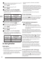
Tool Use and Care
• Do not use the laser if the Power/Transport Lock switch
does not turn the laser on or off. Any tool that cannot be
controlled with the switch is dangerous and must be repaired.
• Follow instructions in the Maintenance section of this
manual. Use of unauthorized parts or failure to follow
Maintenance instructions may create a risk of electric shock
or injury.
Battery Safety
The FMHT77598 laser is powered by a Li-ion battery.
WARNING:
To reduce the risk of injury, the user must read the
product User Manual, Laser Safety Manual, and the
Battery Safety Manual.
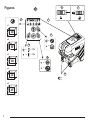
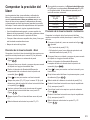
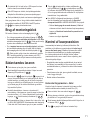
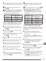
Charging the Battery
Use the charging unit that is packaged with the FMHT77598
laser to charge the laser's Li-ion battery.
1.
Insert the electrical plug at one end of the charging unit
into an electrical outlet (Figure
C
1
).
2.
On the back of the laser, pull the port cover off and to the
side (Figure
C
2
).
3.
Insert the small end of the charging unit into the laser's
charging port (Figure
C
3
).
4.
Allow the battery time to fully-charge. The Power LED will
remain on while the battery is charging.
5.
After the Power LED turns off, disconnect the charging unit
from the electrical outlet and the laser’s charging port.

9
GB
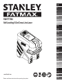
6.
Push the port cover back over the laser’s charging port.
Whenever the laser is not in use, slide the Power/Transport
Lock switch to the LEFT to the Locked/OFF position (Figure
A
6
) to save battery power.
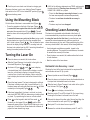
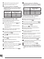
Using the Mounting Block
On the bottom of the laser is a moveable block (Figure
D
).
• To use the magnets on the front of the laser (Figure
A
8
) to mount the laser against the side of a steel beam, do
not extend the moveable block (Figure
D
1
). This will
allow the down dot to be aligned with the edge of the steel
beam.
• To mount the laser over a point on the oor (using a multi-
function bracket or a tripod), pull out the moveable block
until it clicks in place (Figure
D
2
). This will allow the laser
down dot to display through the 5/8-11 mounting hole and
the laser to be rotated over the 5/8-11 mounting hole without
moving the vertical position of the laser.
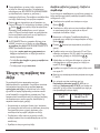
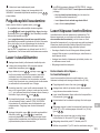
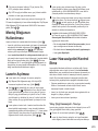
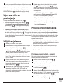
Turning the Laser On
1.
Place the laser on a smooth, flat, level surface.
2.
Slide the Power/Transport Lock switch to the right to the
Unlocked/ON position (Figure
A
7
).
3.
As shown in Figure
A
2
, press once to display
a horizontal laser line, a second time to display a vertical
laser line, a third time to display a horizontal line and
a vertical line, a fourth time to display 5 dots, and a fifth
time to display the horizontal and vertical lines with the 5
dots.
4.
Check the laser beams. The laser is designed to self-level.
If the laser is tilted so much that it cannot self-level (> 4°),
the laser beams will continually flash twice and will flash
constantly on the keypad (Figure
A
3
).
5.
If the laser beams ash, the laser is not level (or plumb)
and should NOT BE USED for determining or marking level
or plumb. Try repositioning the laser on a level surface.
6.
Press on the keypad to test the Pulse mode. will
illuminate on the keypad (Figure
A
5
) and the laser
beams will appear lighter, since they are ashing at a very
rapid rate. You will only use Pulse mode with a detector to
project the laser beams long range.
7.
If ANY of the following statements are TRUE, continue with
the instructions for Checking Laser Accuracy BEFORE
USING THE LASER for a project.
• This is the first time you are using the laser (in case
the laser was exposed to extreme temperatures).
• The laser has not been checked for accuracy in
a while.
• The laser may have been dropped.
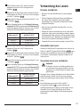
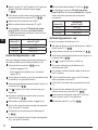
Checking Laser Accuracy
The laser tools are sealed and calibrated at the factory. It
is recommended that you perform an accuracy check prior
to using the laser for the rst time (in case the laser was
exposed to extreme temperatures) and then regularly to
ensure the accuracy of your work. When performing any of the
accuracy checks listed in this manual, follow these guidelines:
• Use the largest area/distance possible, closest to the
operating distance. The greater the area/distance, the easier
to measure the accuracy of the laser.
• Place the laser on a smooth, at, stable surface that is level
in both directions.
• Mark the center of the laser beam.
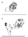
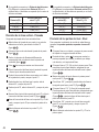
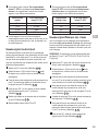
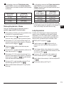
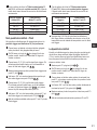
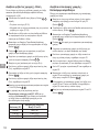
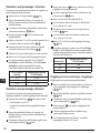
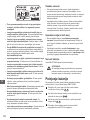
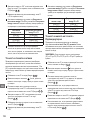
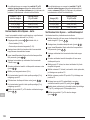
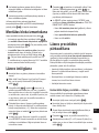
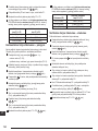
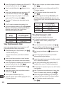
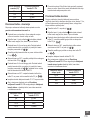
Horizontal Line Accuracy - Level
Checking the level of the laser’s horizontal line requires a at
vertical surface at least 30’ (9 m) wide.
1.
Place a tripod at one end of the wall (Figure
E
1
).
2.
Place the laser on a tripod and screw the threaded knob on
the tripod into the female thread on the laser.
3.
Slide the laser’s Power/Transport Lock switch to the right to
turn the laser ON (Figure
A
7
).
2.
Press once to display a horizontal line.
3.
Mark two points (P1 and P2) at least 30’ (9 m) apart along
the length of the laser’s horizontal line on the wall.
4.
Relocate the laser at the other end of the wall and align the
laser’s horizontal line with point P2 (Figure
E
2
).
5.
Mark point P3 on the laser line near point P1.
6.
Measure the vertical distance between points P1 and P3.

10
GB
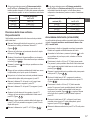
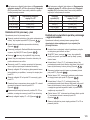
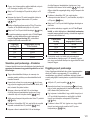
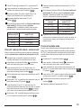
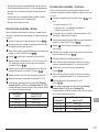
7.
If your measurement is greater than the Allowable
Distance Between P1 & P3 for the corresponding
Distance Between P1 & P2 in the following table, the laser
must be serviced at an authorized service center.
Distance Between
P1 & P2
Allowable Distance
Between P1 and P3
9 m (30’) 6 mm (1/4”)
12 m (40’) 8 mm (5/16”)
15 m (50’) 10 mm (13/32”)
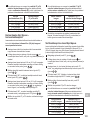
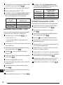
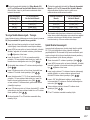
Horizontal Line Accuracy - Tilt
Checking the tilt of the laser’s horizontal line requires a at
vertical surface at least 30’ (9m) wide.
1.
Place a tripod as shown in Figure
F
1
, which is:
• At the center of the wall (D 1/2).
• In front of the wall at a distance of half the size of the wall
(D 1/2).
2.
Place the laser on a tripod and screw the threaded knob on
the tripod into the female thread on the laser.
3.
Slide the laser’s Power/Transport Lock switch to the right to
turn the laser ON (Figure
A
7
).
2.
Press 3 times to display a horizontal line and a vertical
line.
3.
Aim the laser’s vertical line at the rst corner or reference
point (Figure
F
1
).
4.
Measure half the distance across the wall (D1/2).
5.
Where the horizontal laser line crosses the halfway point
(D1/2), mark point P1.
6.
Rotate the laser to another corner or reference point
(Figure
F
2
).
7.
Where the horizontal laser line crosses the halfway point
(D1/2), mark point P2).
8.
Measure the vertical distance between P1 and P2
(Figure
F
3
).
9.
If your measurement is greater than the Allowable
Distance Between P1 & P2 for the corresponding
Distance (D1) in the following table, the laser must be
serviced at an authorized service center.
Distance (D1)
Allowable Distance
Between P1 and P2
9 m (30’) 3 mm (1/8”)
12 m (40’) 4 mm (5/32”)
15 m (50’) 5 mm (7/32”)
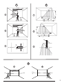
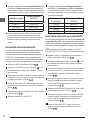
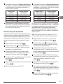
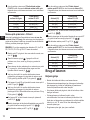
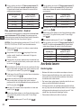
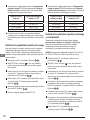
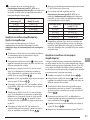
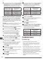
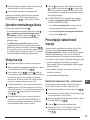
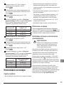
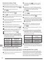
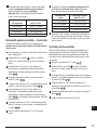
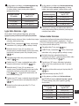
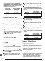
Vertical Line Accuracy - Plumb
Checking the plumb of the laser’s vertical line.
1.
Measure the height of a door jamb (or a reference point on
the ceiling) to get height D1 (Figure
G
1
).
2.
Place the laser on the oor across from the door jam,
(Figure
G
1
).
3.
Slide the laser’s Power/Transport Lock switch to the right to
turn the laser ON (Figure
A
7
).
4.
Press twice to display a vertical line.
5.
Aim the laser’s vertical line toward the door jamb or the
reference point on the ceiling.
6.
Where the laser’s vertical line meets the height of the door
jam, mark point P1.
7.
From where the laser beam hits the oor, measure the D1
distance and mark it point P2.
8.
From P2, measure the D1 distance and mark it point P3.
9.
Move the laser to the opposite side of point P3 and aim the
laser’s vertical line toward point P2 (Figure
G
2
).
10.
Align the laser’s vertical line with points P2 and P3 on the
oor, and mark point P4 over the door jam.
11.
Measure the distance between P1 and P4 (Figure
G
3
).

11
GB
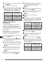
12.
If your measurement is greater than the Allowable Distance
Between P1 & P4 for the corresponding Vertical Distance
(D1) in the following table, the laser must be serviced at an
authorized service center.
Height of Vertical
Distance (D1)
Allowable Distance
Between P1 and P4
2.5m (8’) 1.5mm (1/16")
5m (16′) 3.0mm (1/8”)
6m (20’) 3.6mm (9/64”)
9m (30′) 5.5mm (9/32”)
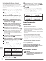
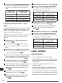
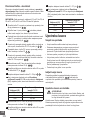
Level Dot Accuracy - Level
Checking the level calibration of the laser unit requires two
parallel walls at least 20’ (6 m) apart.
1.
Place the laser on a tripod and screw the threaded knob on
the tripod into the female thread on the laser.
1.
Turn the laser ON and press 4 times to display dots
above, ahead, below, and to the right and left of the laser.
2.
Place the laser 2”–3” (5–8 cm) from the rst wall. To test
the front laser dot, make sure the front of the laser is facing
the wall (Figure
H
1
).
3.
Mark the laser dot position on the rst wall as point P1
(Figure
H
1
).
4.
Turn the laser 180° and mark the laser dot position on the
second wall as point P2 (Figure
H
1
).
5.
Place the laser 2”–3” (5–8 cm) from the second wall. To test
the front laser dot, make sure the front of the laser is facing
the wall (Figure
H
2
), and adjust the height of the laser
until the laser dot hits point P2.
6.
Turn the laser 180° and aim the laser dot near point P1 on
the rst wall, and mark point P3 (Figure
H
2
).
7.
Measure the vertical distance between points P1 and P3 on
the rst wall.
8.
If your measurement is greater than the Allowable
Distance Between P1 & P3 for the corresponding
Distance Between Walls in the following table, the laser
must be serviced at an authorized service center.
Distance Between
Walls
Allowable Distance
Between P1 & P3
6.0 m (20′) 3.6 mm (9/64”)
9.0 m (30′) 5.4 mm (7/32”)
15.0 m (50′) 9 mm (11/32”)
23.0 m (75′) 13.8 mm (9/16”)
9.
Repeat steps 2 through 8 to check the accuracy of the right
dot and then the left dot, making sure that the laser dot you
are testing is the laser dot facing each wall.
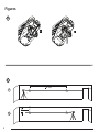
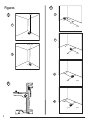
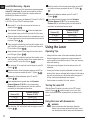
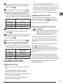
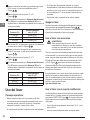
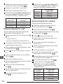
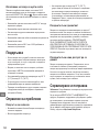
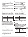
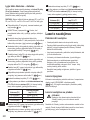
Plumb Dot Accuracy
Checking the plumb calibration of the laser can be most
accurately done when there is a substantial amount of vertical
height available, ideally 25’ (7.5 m), with one person on the oor
positioning the laser and another person near a ceiling to mark
the dot created by the beam on the ceiling.
1.
Mark point P1 on the oor (Figure
I
1
).
2.
Turn the laser ON and press 4 times to display dots
above, ahead, below, and to the right and left of the laser.
3.
Place the laser so that the down dot is centered over point
P1 and mark the center of the up dot on the ceiling as point
P2 (Figure
I
1
).
4.
Turn the laser 180°, making sure that the down dot is still
centered on point P1 on the oor (Figure
I
2
).
5.
Mark the center of the up dot on the ceiling as point P3
(Figure
I
2
).
6.
Measure the distance between points P2 and P3.
7.
If your measurement is greater than the Allowable
Distance Between P2 & P3 for the corresponding
Distance Between Ceiling & Floor in the following table,
the laser must be serviced at an authorized service center.
Distance Between
Ceiling & Floor
Allowable Distance
Between P2 & P3
4.5 m (15′) 3 mm (1/8”)
6 m (20′) 4.2 mm (5/32”)
9 m (30′) 6 mm (1/4”)
12 m (40′) 8.4 mm (5/16”)

12
GB
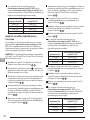
Level Dot Accuracy - Square
Checking the squareness of the laser beams requires a room
at least 35’ (10 m) long. All marks can be made on the oor
by placing a target in front of the level or square beam and
transferring the location to the oor.
NOTE: To ensure accuracy, the distance (D1) from P1 to P2, P2
to P3, P2 to P4, and P2 to P5 should be equal.
1.
Mark point P1 on the oor at one end of the room, as
shown in Figure
J
1
.
2.
Turn the laser ON and press 4 times to display dots
above, ahead, below, and to the right and left of the laser.
3.
Place the laser so that the down dot is centered over point
P1 and make sure the front dot points toward the far end of
the room (Figure
J
1
).
4.
Using a target to transfer the front level dot location on the
wall to the oor, mark point P2 on the floor and then point
P3 on the floor (Figure
J
1
).
5.
Move the laser to point P2 and align the front level dot to
point P3 again (Figure
J
2
).
6.
Using a target to transfer the front level dot location on the
wall to the oor, mark the location of two square beams as
points P4 and P5 on the oor (Figure
J
2
).
7.
Turn the laser 90° so the front level dot aligns to point P4
(Figure
J
3
).
8.
Mark the location of the rst square beam as point P6 on
the oor as close as possible to point P1 (Figure
J
3
).
9.
Measure the distance between points P1 and P6
(Figure
J
3
).
10.
If your measurement is greater than the Allowable
Distance Between P1 & P6 for the corresponding
Distance (D1) in the following table, the laser must be
serviced at an authorized service center.
Distance (D1)
Allowable Distance
Between P1 & P6
7.5 m (25’) 2.2 mm (3/32”)
9 m (30’) 2.7 mm (7/64”)
15 m (50’) 4.5 mm (3/16”)
11.
Turn the laser 180° so the front level dot aligns to point P5
(Figure
J
4
).
12.
Mark the location of the second square beam as point P7
on the oor as close as possible to point P1 (Figure
J
4
).
13.
Measure the distance between points P1 and P7
(Figure
J
4
).
14.
If your measurement is greater than the Allowable
Distance Between P1 & P7 for the corresponding
Distance (D1) in the following table, the laser must be
serviced at an authorized service center.
Distance (D1)
Allowable Distance
Between P1 & P7
7.5 m (25’) 2.2 mm (3/32”)
9 m (30’) 2.7 mm (7/64”)
15 m (50’) 4.5 mm (3/16”)
Using the Laser
Operating Tips
• Always mark the center of the beam created by the laser.
• Extreme temperature changes may cause movement of
internal parts that can affect accuracy. Check your accuracy
often while working.
• If the laser is ever dropped, check to make sure it is still
calibrated.
• As long as the laser is properly calibrated, the laser is self-
leveling. Each laser is calibrated at the factory to nd level as
long as it is positioned on a at surface within average ± 4°
of level. No manual adjustments are required.
• Use the laser on a smooth, at, level, surface.
Turning the Laser Off
Slide the Power/Transport Lock switch to the OFF/Locked
position (Figure
A
6
) when the laser is not in use. If the
switch is not placed in the Locked position, the laser will not
turn off.
Using the Laser with Accessories
WARNING:
Since accessories other than those offered by
Stanley have not been tested with this laser, use of
such accessories with this laser could be hazardous.

13
GB
Only use Stanley accessories that are recommended for use
with this model. Accessories that may be suitable for one laser
may create a risk of injury when used with another laser.
The bottom of the laser is equipped with 1/4-20 and 5/8-11
female threads (Figure
B
) to accommodate current or future
Stanley accessories. Only use Stanley accessories specied
for use with this laser. Follow the directions included with the
accessory.
Recommended accessories for use with this laser are available
at extra cost from your local dealer or authorized service center.
If you need assistance locating any accessory, please contact
your nearest Stanley service center or visit our website:
http://www.2helpU.com.
Using the Laser with the Multibracket
Most line/dot lasers which have a 5/8-11 mounting thread can
be used with the Multibracket FMHT77435 (Figure
K
). The
multibracket can then be used free-standing or mounted in
several ways:
• Use its rubber strap around a pole, 2”×4”, or other vertical
object.
• Use its rear magnets against a metal beam.
• Hook its rear screw hole over a nail or screw on a wall.
• Use its ceiling clamp to hold onto the track for a hanging/
suspended ceiling.
• Use the bottom 5/8-11 or 1/4-20 thread to attach to a tripod.
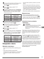
Maintenance
• When the laser is not in use, clean the exterior parts with
a damp cloth, wipe the laser with a soft dry cloth to make
sure it is dry, and then store the laser in the kit box provided.
• Although the laser exterior is solvent resistant, NEVER use
solvents to clean the laser.
• Do not store the laser at temperatures below -20 °C (-5 °F )
or above 60 °C (140 °F).
• To maintain the accuracy of your work, check the laser often
to make sure it is properly calibrated.
• Calibration checks and other maintenance repairs may be
performed by Stanley service centers.
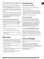
Troubleshooting
The Laser Does Not Turn On
• Make sure the laser’s Li-ion battery is fully-charged.
• Be sure to keep the laser dry.
• If the laser unit is heated above 50 °C (120 °F), the unit
will not turn ON. If the laser has been stored in extremely
hot temperatures, allow it to cool. The laser level will not be
damaged by using the Power/Transport Lock switch before
cooling to its proper operating temperature.
The Laser Beams Flash
The lasers are designed to self-level up to an average of
4° in all directions. If the laser is tilted so much that the
internal mechanism cannot level itself, the laser beams will
ash indicating that the tilt range has been exceeded. THE
FLASHING BEAMS CREATED BY THE LASER ARE NOT
LEVEL OR PLUMB AND SHOULD NOT BE USED FOR
DETERMINING OR MARKING LEVEL OR PLUMB. Try
repositioning the laser on a more level surface.
The Laser Beams Will Not Stop Moving
The laser is a precision instrument. Therefore, if it is not
positioned on a stable (and motionless) surface, the laser will
continue to try to nd level. If the beam will not stop moving, try
placing the laser on a more stable surface. Also, try to make
sure that the surface is relatively at and level, so that the laser
is stable.
Service and Repairs
Note: Disassembling the laser level will void all warranties on
the product.
To assure product SAFETY and RELIABILITY, repairs,
maintenance and adjustment should be performed by
authorized service centers. Service or maintenance performed
by unqualied personnel may result in a risk of injury. To locate
your nearest Stanley service center, go to
http://www.2helpU.com.

14
GB
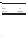
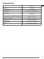
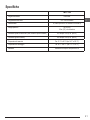
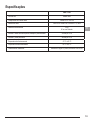
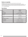
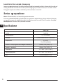
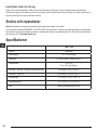
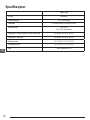
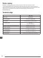
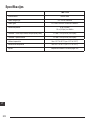
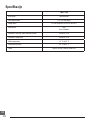
Specications
FMHT77598
Light Source Laser diodes
Laser Wavelength 510 – 530 nm visible
Laser Power ≤1.0 mW CLASS 2 LASER PRODUCT
Working Range 30 m (100’)
50 m (165’) with Detector
Accuracy - all lines and dots, except down dot ±3 mm per 10 m (±1/8” per 30’)
Accuracy - down dot ±6 mm per 10 m (±1/4” per 30’)
Operating Temperature -10 °C to 50 °C (14 °F to 122 °F)
Storage Temperature -20 °C to 60 °C (-5 °F to 140 °F )
Environmental Water & Dust Resistant to IP54

15
D
Inhalt
• Informationen zum Laser
• Benutzersicherheit
• Auaden der Batterie
• Verwendung des Befestigungsblocks
• Einschalten des Lasers
• Prüfen der Lasergenauigkeit
• Verwendung des Lasers
• Wartung
• Fehlerbehebung
• Service und Reparaturen
• Spezikationen
Informationen zum Laser
Der Kreuzlinienlaser FMHT77598 ist ein Laserprodukt der
Klasse 2. Der Laser ist ein selbstnivellierendes Laserwerkzeug,
das für Projekte genutzt werden kann, bei denen eine
horizontale (waagerechte) und vertikale (senkrechte)
Ausrichtung nötig ist.
Benutzersicherheit
Sicherheitsrichtlinien
Im Folgenden wird die Relevanz der einzelnen Warnhinweise
erklärt. Bitte lesen Sie die Betriebsanleitung und achten Sie auf
diese Symbole.
GEFAHR: Weist auf eine unmittelbar drohende
gefährliche Situation hin, die, sofern nicht vermieden,
zu tödlichen oder schweren Verletzungen führt.
WARNUNG: Weist auf eine möglicherweise
gefährliche Situation hin, die, sofern nicht vermieden,
zu tödlichen oder schweren Verletzungen führen
kann.
VORSICHT: Weist auf eine möglicherweise
gefährliche Situation hin, die, sofern nicht vermieden,
zu leichten oder mittelschweren Verletzungen führen
kann.
HINWEIS: Weist auf ein Verhalten hin, das nichts mit
Verletzungen zu tun hat, aber, wenn es nicht vermieden wird,
zu Sachschäden führen kann.
Bei Fragen oder Anmerkungen zu diesem oder anderen
Stanley-Werkzeugen besuchen Sie bitte
http://www.2helpU.com.
EG-Konformitätserklärung
Stanley erklärt hiermit, dass das Produkt FMHT77598 in
Übereinstimmung mit den grundlegenden Anforderungen und allen
anderen Bestimmungen der Richtlinie 1999/5/EC steht.
Der vollständige Text der EU-Konformitätserklärung kann bei
Stanley Tools, Egide Walschaertsstraat 14-16, 2800 Mechelen,
Belgien, oder unter folgender Internetadresse angefordert
werden: www.2helpu.com.
WARNUNG:
Lesen und verstehen Sie alle Anweisungen. Das
Nichtbeachten von Warnhinweisen und Anweisungen
in dieser Anleitung kann schweren Verletzungen
führen.
BEWAHREN SIE DIESE ANWEISUNGEN AUF
WARNUNG:
Belastung durch Laserstrahlung. Zerlegen oder
modizieren Sie den Laser-Nivelliergerät nicht. Im
Inneren benden sich keine zu wartenden Teile.
Es können schwere Augenverletzungen auftreten.
WARNUNG:
Gefährliche Strahlung. Die Verwendung von
Steuerelementen oder Anpassungen sowie die
Durchführung von Verfahren, die nicht den hierin
beschriebenen entsprechen, kann zu gefährlicher
Strahlenbelastung führen.
Das Etikett auf Ihrem Laser kann die folgenden Symbole
enthalten.
Symbol Bedeutung
V Volt
mW Milliwatt
Laser-Warnung
nm Wellenlänge in Nanometer
2 Laser der Klasse 2
Warnetiketten
Für mehr Komfort und Sicherheit sind auf Ihrem Laser
folgende Etiketten angebracht.
WARNUNG: Zur Reduzierung der
Verletzungsgefahr muss jeder Benutzer die
Betriebsanleitung lesen.

16
D
WARNUNG: LASERSTRAHLUNG. BLICKEN
SIE NICHT IN DEN STRAHL. Laserprodukt der
Klasse 2.
7.2V DC 2.0Ah 14.4Wh
FMHT77598 www.STANLEYTOOLS.com
Li-ion
2INR19/66
5002595
EU
Use only with
charger listed
in Operator’s
Manual
• Wird die Anlage in einer vom Hersteller nicht
angegebenen Weise eingesetzt, kann der Schutz durch
die Geräte beeinträchtigt werden.
• Betreiben Sie den Laser nicht in explosionsgefährdeter
Umgebung, in der sich brennbare Flüssigkeiten, Gase
oder Staub benden. Dieses Werkzeug kann Funken
erzeugen, die den Staub oder die Dämpfe entzünden können.
• Bewahren Sie einen nicht verwendeten Laser außerhalb
der Reichweite von Kindern und anderen nicht im
Umgang damit geschulten Personen auf. Laser sind in den
Händen nicht geschulter Personen gefährlich.
• Die Werkzeugwartung MUSS durch qualiziertes
Reparaturpersonal durchgeführt werden. Service
oder Wartung durch nicht qualiziertes Personal kann zu
Verletzungen führen. Ihr nächstgelegenes Stanley Service
Center nden Sie auf http://www.2helpU.com.
• Verwenden Sie keine optischen Werkzeuge wie
Teleskope oder Tachymeter, um den Laserstrahl zu
sehen. Es können schwere Augenverletzungen auftreten.
• Bringen Sie den Laser nicht in eine Stellung, in
der jemand absichtlich oder unbeabsichtigt in
den Laserstrahl blicken kann. Es können schwere
Augenverletzungen auftreten.
• Stellen Sie den Laser nicht in der Nähe einer
reektierenden Oberäche auf, die den Laserstrahl in
Richtung der Augen von Personen ablenken kann. Es
können schwere Augenverletzungen auftreten.
• Schalten Sie den Laser aus, wenn er nicht verwendet
wird. Wenn der Laser eingeschaltet bleibt, erhöht sich das
Risiko, dass jemand in den Laserstrahl blickt.
• Nehmen Sie keinerlei Änderungen am Laser vor.
Veränderungen am Werkzeug können zu gefährlicher
Laserstrahlung führen.
• Betreiben Sie den Laser nicht in der Nähe von Kindern
und lassen Sie ihn nicht von Kindern bedienen. Es
können schwere Augenverletzungen auftreten.
• Entfernen oder beschädigen Sie keine Warnetiketten.
Wenn Etiketten entfernt werden, können der Benutzer oder
andere Personen unbeabsichtigt Strahlung ausgesetzt
werden.
• Stellen Sie den Laser auf einer ebenen Fläche auf.
Wenn der Laser umfällt, kann es zu Schäden daran oder zu
schweren Verletzungen kommen.
Sicherheit von Personen
• Seien Sie aufmerksam, achten Sie darauf, was Sie tun, und
gehen Sie sachgerecht mit dem Laser um. Benutzen Sie den
Laser nicht, wenn Sie müde sind oder unter dem Einuss von
Drogen, Alkohol oder Medikamenten stehen. Ein Moment der
Unachtsamkeit beim Betrieb eines Lasers kann zu schweren
Verletzungen führen.
• Tragen Sie persönliche Schutzausrüstung. Tragen Sie
Augenschutz. Je nach Arbeitsbedingungen empehlt sich das
Tragen von Schutzausrüstung, zum Beispiel Staubmaske,
rutschfeste Sicherheitsschuhe, Schutzhelm und Gehörschutz,
um Verletzungen zu vermeiden.
Verwendung und Pege des Werkzeugs
• Benutzen Sie keinen Laser, dessen Einschalt-/
Transportsperre defekt ist. Ein Werkzeug, das sich nicht
mehr ein- oder ausschalten lässt, ist gefährlich und muss
repariert werden.
• Befolgen Sie die Anweisungen im Abschnitt Wartung dieses
Handbuchs. Die Verwendung nicht genehmigter Teile oder
die Nichtbeachtung der Wartungsanweisungen können zur
Gefahr von Stromschlägen oder Verletzungen führen.
Sicherer Umgang mit Batterien
Der Laser FMHT77598 wird mit einem Li-Ion-Akku betrieben.
WARNUNG:
Um das Risiko von Verletzungen zu verringern,
muss der Benutzer das Produkthandbuch sowie das
Handbuch zum sicheren Umgang mit Lasern und das
Handbuch zum sicheren Umgang mit Batterien lesen.

17
D
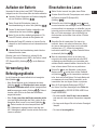
Auaden der Batterie
Verwenden Sie das mit dem Laser FMHT77598 gelieferte
Ladegerät, um den Lithium-Ionen-Akku des Lasers aufzuladen.
1.
Verbinden Sie den Netzstecker am Ende des Ladegeräts
mit einer Steckdose (Abbildung
C
1
).
2.
Ziehen Sie auf der Rückseite des Lasers die
Anschlussabdeckung ab und zur Seite (Abbildung
C
2
).
3.
Stecken Sie das kleinere Ende des Ladegeräts in den
Ladeanschluss des Lasers (Abbildung
C
3
).
4.
Warten Sie, bis der Akku vollständig aufgeladen ist. Die
Power-LED leuchtet, während der Akku geladen wird.
5.
Nachdem die Power-LED erloschen ist, trennen Sie das
Ladegerät von der Steckdose und vom Ladeanschluss des
Lasers.
6.
Schieben Sie die Anschlussabdeckung wieder über den
Ladeanschluss des Lasers.
Wenn der Laser nicht in Gebrauch ist, schieben Sie die
Einschalt-/Transportsperre nach LINKS in die Position Locked/
OFF (Gesperrt/AUS) (Abbildung
A
6
), um die Batterie zu
schonen.
Verwendung des
Befestigungsblocks
An der Unterseite des Lasers bendet sich ein beweglicher
Block (Abbildung
D
).
• Wenn Sie die Magneten an der Vorderseite des Lasers
(Abbildung
A
8
) zum Befestigen des Lasers an einem
Stahlbalken verwenden wollen, darf der bewegliche Block
nicht herausgezogen werden (Abbildung
D
1
). Dadurch
kann der untere Punkt an der Kante des Stahlbalkens
ausgerichtet werden.
• Wenn Sie den Laser über dem Boden verwenden wollen
(an einem Multifunktionsbügel oder Stativ), ziehen Sie den
beweglichen Block heraus, bis er einrastet (Abbildung
D
2
). Dadurch werden der untere Laserpunkt durch das
5/8-11-Montageloch angezeigt und der Laser über dem
5/8-11-Montageloch gedreht, ohne die vertikale Position des
Lasers zu verändern.
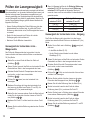
Einschalten des Lasers
1.
Stellen Sie den Laser auf eine glatte, ebene Fläche.
2.
Schieben Sie die Einschalt-/Transportsperre nach rechts in
die Position Unlocked/ON (Entsperrt/AN)
(Abbildung
A
7
).
3.
Drücken Sie wie in Abbildung
A
2
gezeigt einmal,
um eine horizontale Linie anzuzeigen, und ein zweites Mal,
um eine vertikale Linie anzuzeigen, ein drittes Mal, um eine
horizontale und eine vertikale Linie anzuzeigen, ein fünftes
Mal, um 5 Punkte anzuzeigen, und ein fünftes Mal, um
die horizontalen und vertikalen Linien mit den 5 Punkten
anzuzeigen.
4.
Überprüfen Sie die Laserstrahlen. Der Laser ist so
konstruiert, dass er sich selbst nivellieren kann. Wenn
der Laser so stark geneigt ist, dass er sich nicht selbst
nivellieren kann (> 4°), blinken die Laserstrahlen
kontinuierlich zwei Mal und
auf dem Tastenfeld blinken
sie dauerhaft (Abbildung
A
3
).
5.
Wenn die Laserstrahlen blinken, ist der Laser nicht
horizontal (oder vertikal) ausgerichtet und sollte NICHT
zur Bestimmung oder Markierung von horizontalen oder
vertikalen Ebenen verwendet werden. Versuchen Sie, den
Laser auf einer ebenen Fläche neu zu positionieren.
6.
Drücken Sie auf dem Tastenfeld, um den Impuls-
Modus zu testen. leuchtet dann auf dem Tastenfeld
auf (Abbildung
A
5
) und die Laserstrahlen erscheinen
heller, da sie sehr schnell blinken. Der Impuls-Modus wird
nur zusammen mit einem Detektor verwendet, um die
Laserstrahlen über eine längere Strecke zu projizieren.
7.
Wenn ALLE der folgenden Bedingungen ERFÜLLT
sind, fahren Sie mit den Anweisungen unter Prüfen der
Lasergenauigkeit fort, BEVOR SIE DEN LASER für ein
Projekt VERWENDEN.
• Es ist das erste Mal, dass Sie den Laser verwenden
(oder wenn der Laser extremen Temperaturen ausgesetzt
war).
• Der Laser wurde längere Zeit nicht auf seine Genauigkeit
überprüft.
• Der Laser ist heruntergefallen.

18
D
Prüfen der Lasergenauigkeit
Die Laserwerkzeuge wurden werkseitig versiegelt und kalibriert.
Es wird empfohlen, vor der ersten Verwendung des Lasers (und
falls der Laser extremen Temperaturen ausgesetzt war) und
danach regelmäßig eine Genauigkeitskontrolle durchzuführen,
um die Genauigkeit Ihrer Arbeit zu gewährleisten. Beachten Sie
bei den Genauigkeitsprüfungen gemäß diesem Handbuch die
folgenden Richtlinien:
• Nutzen Sie die größtmögliche Fläche/Entfernung, die dem
Arbeitsabstand am nächsten liegt. Je größer die Fläche/
Entfernung, desto leichter ist es, die Genauigkeit des Lasers
zu messen.
• Stellen Sie den Laser auf eine Fläche, die in beide
Richtungen glatt, stabil und eben ist.
• Markieren Sie die Mitte des Laserstrahls.
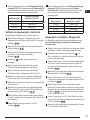
Genauigkeit der horizontalen Linie -
Waagerechte
Das Prüfen der Waagerechten der horizontalen Linie des
Lasers erfordert eine ebene vertikale Fläche von mindestens
30’ (9 m) Breite.
1.
Stellen Sie an einem Ende der Wand ein Stativ auf
(Abbildung
E
1
).
2.
Setzen Sie den Laser auf das Stativ und schrauben Sie den
Gewindeteil am Stativ in das Innengewinde des Laser.
3.
Schieben Sie die Einschalt-/Transportsperre des Lasers
nach rechts, um den Laser einzuschalten
(Abbildung
A
7
).
2.
Drücken Sie einmal, um eine horizontale Linie
anzuzeigen.
3.
Markieren Sie entlang der Länge der horizontalen Linie
des Lasers an der Wand zwei Punkte (P1 und P2), die
mindestens 30‘ (9 m) auseinander liegen.
4.
Stellen Sie den Laser am anderen Ende der Wand auf und
richten Sie die horizontale Linie des Lasers an Punkt P2
aus (Abbildung
E
2
).
5.
Markieren Sie Punkt P3 auf der Laserlinie nahe an Punkt
P1.
6.
Messen Sie die vertikale Entfernung zwischen den Punkten
P1 und P3.
7.
Wenn Ihr Messwert größer als die Zulässige Entfernung
zwischen P1 & P3 für die entsprechende Entfernung
zwischen P1 & P2 gemäß der folgenden Tabelle ist,
muss der Laser von einer autorisierten Kundendienststelle
gewartet werden.
Entfernung
zwischen P1 & P2
Zulässige Entfernung
zwischen P1 und P3
9 m (30’) 6 mm (1/4")
12 m (40’) 8 mm (5/16")
15 m (50’) 10 mm (13/32")
Genauigkeit der horizontalen Linie - Neigung
Das Prüfen der Neigung der horizontalen Linie des Lasers
erfordert eine ebene vertikale Fläche von mindestens 30' (9 m)
Breite.
1.
Stellen Sie ein Stativ wie in Abbildung
F
1
gezeigt auf,
und zwar:
• In der Mitte der Wand (D 1/2).
• Vor der Wand in einem Abstand von der halben
Wandlänge (D 1/2).
2.
Setzen Sie den Laser auf das Stativ und schrauben Sie den
Gewindeteil am Stativ in das Innengewinde des Laser.
3.
Schieben Sie die Einschalt-/Transportsperre des Lasers
nach rechts, um den Laser einzuschalten
(Abbildung
A
7
).
2.
Drücken Sie 3 Mal, um eine horizontale Linie und eine
vertikale Linie anzuzeigen.
3.
Richten Sie die vertikale Linie des Lasers an der ersten
Ecke oder dem Bezugspunkt aus (Abbildung
F
1
).
4.
Messen Sie die halbe Entfernung über die Wand (D1/2).
5.
Wo die horizontale Laserlinie den Punkt der halben
Entfernung kreuzt (D1/2), markieren Sie Punkt P1.
6.
Drehen Sie den Laser in Richtung einer anderen Ecke oder
eines anderen Referenzpunkts (Abbildung
F
2
).
7.
Wo die horizontale Laserlinie den Punkt der halben
Entfernung kreuzt (D
1/2), markieren Sie Punkt P2.
8.
Messen Sie die vertikale Entfernung zwischen P1 und P2
(Abbildung
F
3
).

19
D
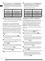
9.
Wenn Ihr Messwert größer als die Zulässige Entfernung
zwischen P1 & P2 für die entsprechende Entfernung (D1)
gemäß der folgenden Tabelle ist, muss der Laser von einer
autorisierten Kundendienststelle gewartet werden.
Entfernung (D1)
Zulässige Entfernung
zwischen P1 und P2
9 m (30’) 3 mm (1/8")
12 m (40’) 4 mm (5/32")
15 m (50’) 5 mm (7/32")
Vertikale Liniengenauigkeit - Senkrechte
Überprüfung der Senkrechten der vertikalen Laserlinie.
1.
Messen Sie die Höhe eines Türpfostens (oder eines
Bezugspunkts an der Decke), um die Höhe D1 zu erhalten
(Abbildung
G
1
).
2.
Stellen Sie den Laser gegenüber dem Türpfosten auf den
Boden, (Abbildung
G
1
).
3.
Schieben Sie die Einschalt-/Transportsperre des Lasers
nach rechts, um den Laser einzuschalten
(Abbildung
A
7
).
4.
Drücken Sie zweimal, um eine vertikale Linie
anzuzeigen.
5.
Richten Sie die vertikale Linie des Lasers auf den
Türpfosten oder den Bezugspunkt an der Decke.
6.
Wenn die vertikale Linie des Lasers die Höhe des
Türpfostens erreicht, markieren Sie den Punkt mit P1.
7.
Messen Sie von dort, wo der Laserstrahl auf den Boden
trifft, den Abstand D1 und markieren Sie den Punkt P2.
8.
Messen Sie von P2 aus den Abstand D1 und markieren Sie
den Punkt mit P3.
9.
Stellen Sie den Laser auf dann der gegenüberliegenden
Seite von Punkt P3 auf und richten Sie die vertikale Linie
des Lasers auf Punkt P2 (Abbildung
G
2
).
10.
Richten Sie die vertikale Linie des Lasers an den Punkten
P2 und P3 am Boden aus und markieren Sie Punkt P4 über
dem Türpfosten.
11.
Messen Sie die Entfernung zwischen P1 und P4
(Abbildung
G
3
).
12.
Wenn Ihr Messwert größer als die Zulässige Entfernung
zwischen P1 & P4 für die entsprechende Vertikale
Entfernung (D1) gemäß der folgenden Tabelle ist, muss
der Laser von einer autorisierten Kundendienststelle
gewartet werden.
Höhe der vertikalen
Entfernung (D1)
Zulässige Entfernung
zwischen P1 und P4
2,5 m (8’) 1,5 mm (1/16")
5 m (16’) 3,0 mm (1/8")
6 m (20’) 3,6 mm (9/64")
9 m (30’) 5,5 mm (9/32")
Genauigkeit von Punkten - Waagerechte
Zur Überprüfung der Kalibrierung des Lasergeräts sind zwei
parallele Wände nötig, die mindestens 6 m Abstand zu
einander haben.
1.
Setzen Sie den Laser auf das Stativ und schrauben Sie den
Gewindeteil am Stativ in das Innengewinde des Laser.
1.
Schalten Sie den Laser ein und drücken Sie vier
Mal, um oberhalb, vor, unterhalb und rechts und links des
Lasers Punkte anzuzeigen.
2.
Stellen Sie den Laser 5–8 cm von der ersten Wand entfernt
auf. Um den vorderen Laserpunkt zu testen, stellen Sie
sicher, dass die Vorderseite des Lasers zur Wand zeigt
(Abbildung
H
1
).
3.
Markieren Sie die Position des Laserpunktes auf der ersten
Wand als Punkt P1 (Abbildung
H
1
).
4.
Drehen Sie den Laser um 180° und markieren Sie die
Position des Laserpunktes auf der zweiten Wand als Punkt
P2 (Abbildung
H
1
).
5.
Stellen Sie den Laser 5–8 cm von der zweiten Wand
entfernt auf. Um den vorderen Laserpunkt zu testen, stellen
Sie sicher, dass die Vorderseite des Lasers zur Wand zeigt
(Abbildung
H
2
) und justieren Sie die Höhe des Lasers,
bis der Laserpunkt P2 trifft.
6.
Drehen Sie den Laser um 180°, zielen Sie auf eine Stelle
nahe Punkt P1 auf der ersten Wand und markieren Sie dort
Punkt P3 (Abbildung
H
2
).
7.
Messen Sie die vertikale Entfernung zwischen den Punkten
P1 und P3 auf der ersten Wand.

20
D
8.
Wenn Ihr Messwert größer als die Zulässige Entfernung
zwischen P1 & P3 für die entsprechende Entfernung
zwischen den Wänden gemäß der folgenden Tabelle ist,
muss der Laser von einer autorisierten Kundendienststelle
gewartet werden.
Entfernung zwischen
den Wänden
Zulässige Entfernung
zwischen P1 & P3
6,0 m (20’) 3,6 mm (9/64")
9,0 m (30’) 5,4 mm (7/32")
15,0 m (50’) 9 mm (11/32")
23,0 m (75’) 13,8 mm (9/16")
9.
Wiederholen Sie die Schritte 2 bis 8, um die Genauigkeit
des rechten und dann des linken Punktes zu überprüfen,
und stellen Sie dabei sicher, das der überprüfte Laserpunkt
derjenige ist, der jeder Wand gegenüberliegt.
Genauigkeit von senkrechten Punkten
Das Überprüfen der senkrechten Kalibrierung des Lasers erfolgt
am besten, wenn eine große vertikale Höhe zur Verfügung
steht, idealerweise 25' (7,5 m), wobei eine Person sich auf dem
Boden bendet und den Laser positioniert und eine andere
Person sich in der Nähe der Decke bendet, um den Punkt zu
markieren, der durch den Strahl an der Decke erzeugt wird.
1.
Markieren Sie Punkt P1 auf dem Boden (Abbildung
I
1
).
2.
Schalten Sie den Laser ein und drücken Sie vier
Mal, um oberhalb, vor, unterhalb und rechts und links des
Lasers Punkte anzuzeigen.
3.
Stellen Sie den Laser so hin, dass der untere Punkt über
dem Punkt P1 zentriert ist, und markieren Sie die Mitte des
oberen Punktes an der Decke als Punkt P2
(Abbildung
I
1
).
4.
Drehen Sie den Laser um 180° und vergewissern Sie sich,
dass der untere Punkt immer noch auf Punkt P1 auf dem
Boden zentriert ist (Abbildung
I
2
).
5.
Markieren Sie die Mitte des oberen Punktes an der Decke
als Punkt P3 (Abbildung
I
2
).
6.
Messen Sie die Entfernung zwischen den Punkten P2 und
P3.
7.
Wenn Ihr Messwert größer als die Zulässige Entfernung
zwischen P2 & P3 für die entsprechende Entfernung
zwischen Decke & Boden gemäß der folgenden
Tabelle ist, muss der Laser von einer autorisierten
Kundendienststelle gewartet werden.
Entfernung zwischen
Decke und Boden
Zulässige Entfernung
zwischen P2 & P3
4,5 m (15’) 3 mm (1/8“)
6 m (20’) 4,2 mm (5/32“)
9 m (30’) 6 mm (1/4“)
12 m (40’) 8,4 mm (5/16“)
Genauigkeit von Punkten - Senkrechte
Zur Überprüfung der Senkrechten der Laserstrahlen ist ein
Raum mit mindestens 10 m Länge nötig. Alle Markierungen
können auf dem Boden vorgenommen werden, indem ein
Zielobjekt vor dem waagerechten oder senkrechten Strahl
platziert und auf die Stelle am Boden übertragen wird.
HINWEIS: Zur Gewährleistung der Genauigkeit sollte die
Entfernung (D1) von P1 zu P2, P2 zu P3, P2 zu P4 und P2 zu
P5 gleich sein.
1.
Markieren Sie Punkt P1 an einem Ende des Raums auf
dem Boden, wie in Abbildung
J
1
gezeigt.
2.
Schalten Sie den Laser ein und drücken Sie vier
Mal, um oberhalb, vor, unterhalb und rechts und links des
Lasers Punkte anzuzeigen.
3.
Stellen Sie den Laser so hin, dass der untere Punkt über
dem Punkt P1 zentriert ist, und stellen Sie sicher, dass der
vordere Punkt in Richtung des hinteren Ende des Raums
zeigt (Abbildung
J
1
).
4.
Verwenden Sie ein Zielobjekt, um die Position des vorderen
waagerechten Punktes an der Wand auf den Boden zu
übertragen, markieren Sie auf dem Boden Punkt P2 und
dann Punkt P3 (Abbildung
J
1
).
5.
Bewegen Sie den Laser auf Punkt P2 und richten Sie den
vorderen waagerechten Punkt wieder an Punkt P3 aus
(Abbildung
J
2
).
6.
Verwenden Sie ein Zielobjekt, um die Position des vorderen
waagerechten Punktes an der Wand auf den Boden zu
übertragen, und markieren Sie die Position der zwei
senkrechten Strahlen auf dem Boden als die Punkte P4
und P5 (Abbildung
J
2
).
Pagina se încarcă...
Pagina se încarcă...
Pagina se încarcă...
Pagina se încarcă...
Pagina se încarcă...
Pagina se încarcă...
Pagina se încarcă...
Pagina se încarcă...
Pagina se încarcă...
Pagina se încarcă...
Pagina se încarcă...
Pagina se încarcă...
Pagina se încarcă...
Pagina se încarcă...
Pagina se încarcă...
Pagina se încarcă...
Pagina se încarcă...
Pagina se încarcă...
Pagina se încarcă...
Pagina se încarcă...
Pagina se încarcă...
Pagina se încarcă...
Pagina se încarcă...
Pagina se încarcă...
Pagina se încarcă...
Pagina se încarcă...
Pagina se încarcă...
Pagina se încarcă...
Pagina se încarcă...
Pagina se încarcă...
Pagina se încarcă...
Pagina se încarcă...
Pagina se încarcă...
Pagina se încarcă...
Pagina se încarcă...
Pagina se încarcă...
Pagina se încarcă...
Pagina se încarcă...
Pagina se încarcă...
Pagina se încarcă...
Pagina se încarcă...
Pagina se încarcă...
Pagina se încarcă...
Pagina se încarcă...
Pagina se încarcă...
Pagina se încarcă...
Pagina se încarcă...
Pagina se încarcă...
Pagina se încarcă...
Pagina se încarcă...
Pagina se încarcă...
Pagina se încarcă...
Pagina se încarcă...
Pagina se încarcă...
Pagina se încarcă...
Pagina se încarcă...
Pagina se încarcă...
Pagina se încarcă...
Pagina se încarcă...
Pagina se încarcă...
Pagina se încarcă...
Pagina se încarcă...
Pagina se încarcă...
Pagina se încarcă...
Pagina se încarcă...
Pagina se încarcă...
Pagina se încarcă...
Pagina se încarcă...
Pagina se încarcă...
Pagina se încarcă...
Pagina se încarcă...
Pagina se încarcă...
Pagina se încarcă...
Pagina se încarcă...
Pagina se încarcă...
Pagina se încarcă...
Pagina se încarcă...
Pagina se încarcă...
Pagina se încarcă...
Pagina se încarcă...
Pagina se încarcă...
Pagina se încarcă...
Pagina se încarcă...
Pagina se încarcă...
Pagina se încarcă...
Pagina se încarcă...
Pagina se încarcă...
Pagina se încarcă...
Pagina se încarcă...
Pagina se încarcă...
Pagina se încarcă...
Pagina se încarcă...
Pagina se încarcă...
Pagina se încarcă...
Pagina se încarcă...
Pagina se încarcă...
Pagina se încarcă...
Pagina se încarcă...
Pagina se încarcă...
Pagina se încarcă...
Pagina se încarcă...
Pagina se încarcă...
Pagina se încarcă...
Pagina se încarcă...
Pagina se încarcă...
Pagina se încarcă...
Pagina se încarcă...
Pagina se încarcă...
Pagina se încarcă...
Pagina se încarcă...
Pagina se încarcă...
Pagina se încarcă...
Pagina se încarcă...
Pagina se încarcă...
Pagina se încarcă...
Pagina se încarcă...
Pagina se încarcă...
Pagina se încarcă...
Pagina se încarcă...
Pagina se încarcă...
Pagina se încarcă...
Pagina se încarcă...
Pagina se încarcă...
Pagina se încarcă...
Pagina se încarcă...
Pagina se încarcă...
Pagina se încarcă...
Pagina se încarcă...
Pagina se încarcă...
Pagina se încarcă...
Pagina se încarcă...
Pagina se încarcă...
Pagina se încarcă...
Pagina se încarcă...
Pagina se încarcă...
Pagina se încarcă...
Pagina se încarcă...
Pagina se încarcă...
Pagina se încarcă...
Pagina se încarcă...
Pagina se încarcă...
Pagina se încarcă...
Pagina se încarcă...
Pagina se încarcă...
Pagina se încarcă...
Pagina se încarcă...
Pagina se încarcă...
Pagina se încarcă...
Pagina se încarcă...
Pagina se încarcă...
Pagina se încarcă...
Pagina se încarcă...
Pagina se încarcă...
Pagina se încarcă...
Pagina se încarcă...
Pagina se încarcă...
Pagina se încarcă...
Pagina se încarcă...
Pagina se încarcă...
Pagina se încarcă...
Pagina se încarcă...
Pagina se încarcă...
Pagina se încarcă...
Pagina se încarcă...
Pagina se încarcă...
Pagina se încarcă...
Pagina se încarcă...
Pagina se încarcă...
Pagina se încarcă...
Pagina se încarcă...
Pagina se încarcă...
Pagina se încarcă...
Pagina se încarcă...
Pagina se încarcă...
Pagina se încarcă...
Pagina se încarcă...
Pagina se încarcă...
Pagina se încarcă...
Pagina se încarcă...
Pagina se încarcă...
Pagina se încarcă...
Pagina se încarcă...
Pagina se încarcă...
Pagina se încarcă...
Pagina se încarcă...
Pagina se încarcă...
Pagina se încarcă...
Pagina se încarcă...
Pagina se încarcă...
Pagina se încarcă...
Pagina se încarcă...
Pagina se încarcă...
Pagina se încarcă...
Pagina se încarcă...
Pagina se încarcă...
Pagina se încarcă...
Pagina se încarcă...
Pagina se încarcă...
Pagina se încarcă...
Pagina se încarcă...
-
 1
1
-
 2
2
-
 3
3
-
 4
4
-
 5
5
-
 6
6
-
 7
7
-
 8
8
-
 9
9
-
 10
10
-
 11
11
-
 12
12
-
 13
13
-
 14
14
-
 15
15
-
 16
16
-
 17
17
-
 18
18
-
 19
19
-
 20
20
-
 21
21
-
 22
22
-
 23
23
-
 24
24
-
 25
25
-
 26
26
-
 27
27
-
 28
28
-
 29
29
-
 30
30
-
 31
31
-
 32
32
-
 33
33
-
 34
34
-
 35
35
-
 36
36
-
 37
37
-
 38
38
-
 39
39
-
 40
40
-
 41
41
-
 42
42
-
 43
43
-
 44
44
-
 45
45
-
 46
46
-
 47
47
-
 48
48
-
 49
49
-
 50
50
-
 51
51
-
 52
52
-
 53
53
-
 54
54
-
 55
55
-
 56
56
-
 57
57
-
 58
58
-
 59
59
-
 60
60
-
 61
61
-
 62
62
-
 63
63
-
 64
64
-
 65
65
-
 66
66
-
 67
67
-
 68
68
-
 69
69
-
 70
70
-
 71
71
-
 72
72
-
 73
73
-
 74
74
-
 75
75
-
 76
76
-
 77
77
-
 78
78
-
 79
79
-
 80
80
-
 81
81
-
 82
82
-
 83
83
-
 84
84
-
 85
85
-
 86
86
-
 87
87
-
 88
88
-
 89
89
-
 90
90
-
 91
91
-
 92
92
-
 93
93
-
 94
94
-
 95
95
-
 96
96
-
 97
97
-
 98
98
-
 99
99
-
 100
100
-
 101
101
-
 102
102
-
 103
103
-
 104
104
-
 105
105
-
 106
106
-
 107
107
-
 108
108
-
 109
109
-
 110
110
-
 111
111
-
 112
112
-
 113
113
-
 114
114
-
 115
115
-
 116
116
-
 117
117
-
 118
118
-
 119
119
-
 120
120
-
 121
121
-
 122
122
-
 123
123
-
 124
124
-
 125
125
-
 126
126
-
 127
127
-
 128
128
-
 129
129
-
 130
130
-
 131
131
-
 132
132
-
 133
133
-
 134
134
-
 135
135
-
 136
136
-
 137
137
-
 138
138
-
 139
139
-
 140
140
-
 141
141
-
 142
142
-
 143
143
-
 144
144
-
 145
145
-
 146
146
-
 147
147
-
 148
148
-
 149
149
-
 150
150
-
 151
151
-
 152
152
-
 153
153
-
 154
154
-
 155
155
-
 156
156
-
 157
157
-
 158
158
-
 159
159
-
 160
160
-
 161
161
-
 162
162
-
 163
163
-
 164
164
-
 165
165
-
 166
166
-
 167
167
-
 168
168
-
 169
169
-
 170
170
-
 171
171
-
 172
172
-
 173
173
-
 174
174
-
 175
175
-
 176
176
-
 177
177
-
 178
178
-
 179
179
-
 180
180
-
 181
181
-
 182
182
-
 183
183
-
 184
184
-
 185
185
-
 186
186
-
 187
187
-
 188
188
-
 189
189
-
 190
190
-
 191
191
-
 192
192
-
 193
193
-
 194
194
-
 195
195
-
 196
196
-
 197
197
-
 198
198
-
 199
199
-
 200
200
-
 201
201
-
 202
202
-
 203
203
-
 204
204
-
 205
205
-
 206
206
-
 207
207
-
 208
208
-
 209
209
-
 210
210
-
 211
211
-
 212
212
-
 213
213
-
 214
214
-
 215
215
-
 216
216
-
 217
217
-
 218
218
-
 219
219
-
 220
220


Stanley FMHT77598 Manual de utilizare
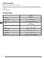
- Categorie
- Nivelurile laserului
- Tip
- Manual de utilizare
- Acest manual este potrivit și pentru
în alte limbi
- slovenčina: Stanley FMHT77598 Používateľská príručka
- eesti: Stanley FMHT77598 Kasutusjuhend
Lucrări înrudite
-
Stanley FMHT77597 Manual de utilizare
-
Stanley FMHT77 Series Instrucțiuni de utilizare
-
-
-
-
-
Stanley FMHT1-77438 Manual de utilizare
-
Stanley STHT77503-1 Manual de utilizare
-
Stanley FMHT77619-1 Manual de utilizare
-