Whirlpool KN3G76SA(X)/UA Manualul utilizatorului
- Categorie
- Microunde
- Tip
- Manualul utilizatorului

English
GB
Operating Instructions
COOKER AND OVEN
Contents
Operating Instructions,1
Description of the appliance-Overall view,2
Description of the appliance-Control Panel,3
Installation,4
Start-up and use,8
Cooking modes,9
Precautions and tips,12
Care and maintenance,13
Assistance,13
KN3G76SA/UA
CZ
Cesky
Pokyny pro použití
SPORÁK S TROUBOU
Obsah
Pokyny pro použití,1
Popis zarízení-Celkový pohled,2
Popis zarízení-Ovládací panel,3
Instalace,25
Spuštení a použití, 29
Použití varné desky,30
Opatrení a rady,34
Údržba a péce,35
Servisní služba,35
HU
Magyar
Használati útmutató
tűzhely és a sütő
Tartalomjegyzék
Használati útmutató,1
A készülék leírása- A készülék áttekintése,2
A készülék leírása- Kezelőpanel,3
Üzembe helyezés,14
Bekapcsolás és használat,18
A főzőlap használata,19
Óvintézkedések és tanácsok,23
Karbantartás és ápolás,24
Szerviz,24
Украінська
UA
Інструкціі з експлуатаціі
КУХНЯ
Зміст
Інструкціі з експлуатаціі,1
Опис установки-Загальнии вигляд,2
Опис установки-Панель управління,3
Встановлення,47
Включення і використання,51
Запобіжні засоби і поради,55
Догляд i технічне обслуговування,56
Допомога,56
RO
Românã
Instrucţiuni de folosire
ARAGAZ
ŞI
CUPTOR
Sumar
Instrucţiuni de folosire,1
Descrierea aparatului- Vedere de ansamblu,2
Descrierea aparatului-Panoul de control,3
Instalare,36
Pornire şi utilizare, 40
Precauţii şi sfaturi,45
Întreţinere şi curăţire,46
Asistenţă,46
BG
Български
Инструкции за употреба
ЕЛЕКТРИЧЕСКА ПЕЧКА И ФУРНА
Резюме
Инструкции за употреба,1
Описание на уреда-Общ преглед,2
Описание на уреда- Управляващ панел,3
Инсталиране,57
Пуск и експлоатация, 61
Предпазни мерки и препоръки,65
Поддръжка и почистване,68
Техническо обслужване,68

2
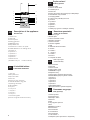
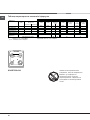
1.Hob burner
2.Hob Grid
3.Control panel
4.Sliding grill rack
5.DRIPPING pan
6.Adjustable foot
7.Containment surface for spills
8.GUIDE RAILS for the sliding racks
9.position 5
10.position 4
11.position 3
12.position 2
13.position 1
14.Glass Cover
(Available only on certain models)
Description of the appliance
Overall view
GB
1. Gáz égõ
2.Edénytartó rács
3.Kapcsoló tábla
4.Sütõ rács
5.Serpenyõ vagy sütõtepsi
6. Állítható lábacska vagy láb
7.Zsírfelfogó borítólap
8.TÁLCASíNEK
9.helyzet 5
10. helyzet 4
11.helyzet 3
12.helyzet 2
13. helyzet 1
14.Ha felmelegedik
(Csak az üvegtetõs modellek esetén)
A készülék leírása
A készülék áttekintése
HU
Popis zarízení
Celkový pohled
CZ
1.Plynový hořák
2. Rošt na varné desce
3. Ovládací panel
4.Pečící rošt
5.Pečící plech nebo plech zachycující odkapávající
6. Nastavitelné nohy omastek
7. Záchytný žlábek
8. Vodicí LIŠTY jednotlivých úrovní
9. poloha 5
10. poloha 4
11.poloha 3
12.poloha 2
13.poloha 1
14.Skleny kryt (pouze u některých modelů)
1
2
3
4
5
6
7
8
9
10
11
12
13
6
14
UA
Опис пристрою
загальний вид
1.Hob пальники
2.Hob сітки
3.Control панелі
4.Sliding гриль стійці
5.DRIPPING каструлі
6.Adjustable ногу
7.Containment поверхню для розливу
8.GUIDE РЕЙКИ для розсувних стелажів
9.position 5
10.position 4
11.position 3
12.position 2
13.position 1
14.Glass Обкладинка
(Доступно тільки на деяких моделях)
1 Arzătoare pe gaz
2 Grătare plită
3 Panou frontal de control
4 Grătarul cuptorului
5 Tavă de coacere
6 Picioare reglabile
7 Plită
8 GHIDAJE alunecare rafturi
9 nivelul 5
10 nivelul 4
11 nivelul 3
12 nivelul 2
13 nivelul 1
14 Capacul din sticlă
Descriere aparatului
Vedere de ansamblu
RO
1.Газови горелки
2.Горна решетка
3.Командно табло
4.Pешетка
5.Тава
6. Регулируеми крачета
7.Плот
8.BOДAЧИ за двата
9.Положение 5
10.Положение 4
11.Положение 3
12.Положение 2
13. Положение 1
14.3a6paHa (само при някои от моделите)
Описание на уреда
Общ преглед
BG

3
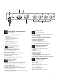
Description of the appliance
Control panel
GB
A készülék leírása
Kezelőpanel
HU
Popis zarízení
Ovládací panel
CZ
UA
Опис плити
Панель управління
Описание на уреда
Управляващ панел
BG
Descriere aparatului
Panoul de control
RO
5
6
8
7
2
4
3
1
1.Electronic cooking programmer
2.TIMER button
3.COOKING TIME button
4.COOKING END TIME button
5.THERMOSTAT knob
6.THERMOSTAT indicator light
7.SELECTOR knob
8.Hob BURNER control knob
1.Електронний програматор приготування їжі
2.Кнопка ТАЙМЕР
3.Кнопка ТРИВАЛІСТЬ ПРИГОТУВАННЯ
4.Кнопка ЗАКIНЧЕННЯ ПРИГОТУВАННЯ
5.Peґyлятор TEPMOCTATУ
6. Індикатор TEPMOCTATУ
7.Peґyлятор РСПГСБМ
8.Ручки для керування газовими
пальниками на варильній поверхні
1. Електронна готвене програмист
2. TIMER
3. Време за готвене
4. Края на готвенето
5. Бучка термостат
6. Светлинен индикатор на термостата
7. ключа за избор
8. Копчето за управление на Котлон горелката
1.Programator electronic
2.Buton TIMER
3.Buton durata de gãtit
4.Buton sfârºitul termenului de gãtit
5.Buton TERMOSTAT
6.Indicator TERMOSTAT
7.Buton PROGRAME
8.Butoane comandi ochiuri aragaz
1.Elektronikus sütés programozó
2.Gomb Időmérő órával és perccel
3.Gomb a sütési időtartam
4.Gomb a sütés vége.
5.Hőmérséklet szabályzó gomb-Termosztát
6.Hőmérséklet ellenőrző lámpa
7.Választó gomb
8.A tűzhely gázégőinek vezérlő gombjai
1.Tlačítko elektronického pečícího programátoru
2.Tlačítko Časovač s hodinami a minutami
3.Tlačítko Délka pečení
4.Tlačítko Doba ukončení pečení
5.Knofl ík nastavení teploty v troubě (termostat)
6.Indikátor termostatu
7.Knofl ík pro výběr režimu
8.Regulační knofl íky pro ovládání hořáků varné desky

4
GB
! Before operating your new appliance please read
this instruction booklet carefully. It contains important
information concerning the safe installation and
operation of the appliance.
! Please keep these operating instructions for future
reference. Make sure that the instructions are kept with
the appliance if it is sold, given away or moved.
! The appliance must be installed by a qualified
professional according to the instructions provided.
! Any necessary adjustment or maintenance must be
performed after the cooker has been disconnected
from the electricity supply.
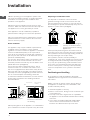
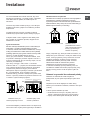
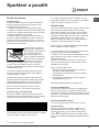
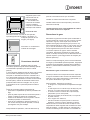
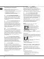
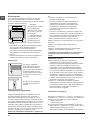
Room ventilation
The appliance may only be installed in permanently-
ventilated rooms, according to current national
legislation. The room in which the appliance is installed
must be ventilated adequately so as to provide as
much air as is needed by the normal gas combustion
process (the flow of air must not be lower than 2 m
3
/h
per kW of installed power).
The air inlets, protected by grilles, should have a duct
with an inner cross section of at least 100 cm
2
and
should be positioned so that they are not liable to even
partial obstruction (see gure A).
These inlets should be enlarged by 100% - with a
minimum of 200 cm
2
- whenever the surface of the
hob is not equipped with a flame failure safety device.
When the flow of air is provided in an indirect manner
from adjacent rooms (see gure B), provided that these
are not communal parts of a building, areas with
increased fire hazards or bedrooms, the inlets should
be fitted with a ventilation duct leading outside as
described above.
! After prolonged use of the appliance, it is advisable to
open a window or increase the speed of any fans used.
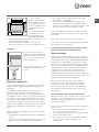
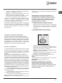
Disposing of combustion fumes
The disposal of combustion fumes should be
guaranteed using a hood connected to a safe and
efficient natural suction chimney, or using an electric
fan that begins to operate automatically every time the
appliance is switched on (see gure).
! The liquefied petroleum gases are heavier than air
and collect by the floor, therefore all rooms containing
LPG cylinders must have openings leading outside so
that any leaked gas can escape easily.
LPG cylinders, therefore, whether partially or
completely full, must not be installed or stored in rooms
or storage areas that are below ground level (cellars,
etc.). Only the cylinder being used should be stored
in the room; this should also be kept well away from
sources of heat (ovens, chimneys, stoves) that may
cause the temperature of the cylinder to rise above
50°C.
Positioning and levelling
! It is possible to install the appliance alongside
cupboards whose height does not exceed that of the
hob surface.
! Make sure that the wall in contact with the back of
the appliance is made from a non-flammable, heat-
resistant material (T 90°C).
To install the appliance correctly:
• Place it in the kitchen, dining room or the bed-sit (not
in the bathroom).
• If the top of the hob is higher than the cupboards,
the appliance must be installed at least 200 mm away
from them.
• If the cooker is installed underneath a wall cabinet,
there must be a minimum distance of 420 mm
between this cabinet and the top of the hob.
Installation
Adjacent room Room requiring
ventilation
A
B
Ventilation opening for
comburent air
Increase in the gap
between the door and
the flooring
A
Fumes channelled
straight outside
Fumes channelled through a
chimney or a branched flue
system (reserved for cooking
appliances)

GB
5
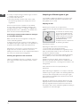
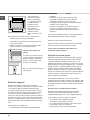
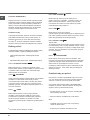
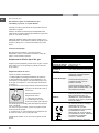
• If the cooker is
installed underneath a
wall cabinet, there must
be a minimum distance
of 420 mm between this
cabinet and the top of
the hob.
This distance should be
increased to 700 mm
if the wall cabinets are
flammable (see gure).
• Do not position blinds behind the cooker or less than
200 mm away from its sides.
• Any hoods must be installed according to the
instructions listed in the relevant operating manual.
Levelling
If it is necessary to level the
appliance, screw the adjustable
feet into the places provided on
each corner of the base of the
cooker (see gure).
The legs* fit into the slots on the
underside of the base of the
cooker.
Electrical connection
Install a standardised plug corresponding to the load
indicated on the appliance data plate (see Technical
data table).
The appliance must be directly connected to the
mains using an omnipolar circuit-breaker with a
minimum contact opening of 3 mm installed between
the appliance and the mains. The circuit-breaker must
be suitable for the charge indicated and must comply
with NFC 15-100 regulations (the earthing wire must
not be interrupted by the circuit-breaker). The supply
cable must be positioned so that it does not come into
contact with temperatures higher than 50°C at any
point.
Before connecting the appliance to the power supply,
make sure that:
• The appliance is earthed and the plug is compliant with
the law.
• The socket can withstand the maximum power of the
appliance, which is indicated by the data plate.
HOOD
420
Min.
min.
650
mm. with hood
min.
700
mm. without hood
mm.
600
Min. mm.
420
Min. mm.
• The voltage is in the range between the values
indicated on the data plate.
• The socket is compatible with the plug of the
appliance. If the socket is incompatible with the
plug, ask an authorised technician to replace it. Do
not use extension cords or multiple sockets.
! Once the appliance has been installed, the power
supply cable and the electrical socket must be easily
accessible.
! The cable must not be bent or compressed.
! The cable must be checked regularly and replaced
by authorised technicians only.
! The manufacturer declines any liability should
these safety measures not be observed.
Gas connection
Connection to the gas network or to the gas cylinder
may be carried out using a flexible rubber or steel hose,
in accordance with current national legislation and after
making sure that the appliance is suited to the type of
gas with which it will be supplied (see the rating sticker
on the cover: if this is not the case see below). When
using liquid gas from a cylinder, install a pressure
regulator which complies with current national
regulations. To make connection easier, the gas
supply may be turned sideways*: reverse the position
of the hose holder with that of the cap and replace the
gasket that is supplied with the appliance.
! Check that the pressure of the gas supply is
consistent with the values indicated in the Table
of burner and nozzle specifications (see below).
This will ensure the safe operation and durability of
your appliance while maintaining efficient energy
consumption.
Gas connection using a flexible rubber hose
Make sure that the hose complies with current national
legislation. The internal diameter of the hose must
measure: 8 mm for liquid gas supply; 13 mm for
methane gas supply.
Once the connection has been performed, make sure
that the hose:
• Does not come into contact with any parts that
reach temperatures of over 50°C.
• Is not subject to any pulling or twisting forces and
that it is not kinked or bent.
• Does not come into contact with blades, sharp
corners or moving parts and that it is not
compressed.

6
GB
• Is easy to inspect along its whole length so that its
condition may be checked.
• Is shorter than 1500 mm.
• Fits firmly into place at both ends, where it will
be fixed using clamps that comply with current
regulations.
! If one or more of these conditions is not fulfilled
or if the cooker must be installed according to the
conditions listed for class 2 - subclass 1 appliances
(installed between two cupboards), the flexible steel
hose must be used instead (see below).
Connecting a flexible jointless stainless steel pipe
to a threaded attachment
Make sure that the hose and gaskets comply with
current national legislation.
To begin using the hose, remove the hose holder on
the appliance (the gas supply inlet on the appliance is
a cylindrical threaded 1/2 gas male attachment).
! Perform the connection in such a way that the hose
length does not exceed a maximum of 2 metres,
making sure that the hose is not compressed and does
not come into contact with moving parts.
Checking the tightness of the connection
When the installation process is complete, check the
hose fittings for leaks using a soapy solution. Never
use a flame.
Adapting to different types of gas
It is possible to adapt the appliance to a type of gas
other than the default type (this is indicated on the
rating label on the cover).
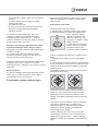
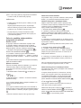
Adapting the hob
Replacing the nozzles for the hob burners:
1. Remove the hob grids and slide the burners off their
seats.
2. Unscrew the nozzles using
a 7 mm socket spanner (see
gure), and replace them with
nozzles suited to the new type
of gas (see Burner and nozzle
speci cations table).
3. Replace all the components
by following the above
instructions in reverse.
Adjusting the hob burners’ minimum setting:
1. Turn the tap to the minimum position.
2. Remove the knob and adjust the regulatory screw,
which is positioned inside or next to the tap pin, until
the flame is small but steady.
! If the appliance is connected to a liquid gas supply,
the regulatory screw must be fastened as tightly as
possible.
3. While the burner is alight, quickly change the
position of the knob from minimum to maximum and
vice versa several times, checking that the flame is not
extinguished.
! The hob burners do not require primary air
adjustment.
! After adjusting the appliance so it may be used with
a different type of gas, replace the old rating label with
a new one that corresponds to the new type of gas
(these labels are available from Authorised Technical
Assistance Centres).
! Should the gas pressure used be different (or vary
slightly) from the recommended pressure, a suitable
pressure regulator must be fitted to the inlet hose in
accordance with current national regulations relating to
“regulators for channelled gas”.

GB
7
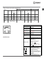
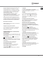
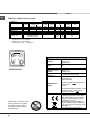
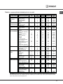
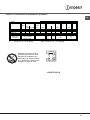
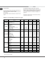
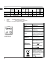
Table of burner and nozzle specifications
KN3G76SA/UA
S
S
R
A
Table 1 Liquid Gas Natural Gas
Burner Diameter
(mm)
Thermal Power
kW (p.c.s.*)
By-Pass
1/100
Nozzle
1/100
Flow*
g/h
Nozzle
1/100
Flow*
l/h
Nominal Reduced (mm) (mm) *** ** (mm)
Fast
(Large)(R)
100 3.00 0.7 41 87 218 214 128 286
Semi Fast
(Medium)(S)
75 1.90 0.4 30 70 138 136 104 181
Auxiliary
(Small)(A)
51 1.00 0.4 30 52 73 71 76 95
Supply
Pressures
Nominal (mbar)
Minimum (mbar)
Maximum (mbar)
30
20
35
30
20
35
20
17
25
TABLE OF CHARACTERISTSICS
Dimensions (with
drawn guide rails)
width 39 cm
height 34 cm
depth 41 cm
Volume (with
drawn guide rails)
54 l
Maximum absorber
power:
See data plate
Dimensions of the
lower compartment
width 42 cm
height 23 cm
depth 44 cm
Burners
may be adapted for use with any type
of gas shown on the data plate, which
is located inside the flap or, after the
oven compartment has been opened,
on the left-hand wall inside the oven.
ENERGY LABEL
Directive 2002/40/EC on the label of
electric ovens.
Standard EN 50304
Energy consumption for Natural
convection – heating mode:
Convection;
Declared energy consumption for
Forced convection Class – heating
mode: Baking
This appliance conforms to the
following European Economic
Community directives: 2006/95/EC
dated 12/12/06 (Low Voltage) and
subsequent amendments -
2004/108/EC dated 15/12/04
(Electromagnetic Compatibility) and
subsequent amendments - 93/68/EEC
dated 22/07/93 and subsequent
amendments.
2002/96/EC
2009/142 of 30/11/09 (Gas)
1275/2008 (Stand-by/ Off mode)

8
GB
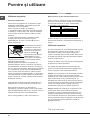
Start-up and use
Using the hob
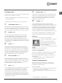
Lighting the burners
For each BURNER knob there is a full ring showing the
strength of the flame for the relevant burner.
To light one of the burners on the hob:
1. Bring a flame or gas lighter close to the burner.
2. Press the BURNER knob and turn it in an
anticlockwise direction so that it is pointing to the
maximum flame setting E.
3. Adjust the intensity of the flame to the desired level
by turning the BURNER knob in an anticlockwise
direction. This may be the minimum setting C, the
maximum setting E or any position in between the two.
If the appliance is fitted with an electronic lighting
device* (C), press the
BURNER knob and turn it in
an anticlockwise direction,
towards the minimum flame
setting, until the burner
is lit. The burner may be
extinguished when the knob is
released. If this occurs, repeat
the operation, holding the knob down for a longer period
of time.
f the appliance is equipped with a flame failure safety
device (X), press and hold the BURNER knob for
approximately 3-7 seconds to keep the flame alight
and to activate the device.
! If the flame is accidentally extinguished, switch off the
burner and wait for at least 1 minute before attempting
to relight it.
To switch the burner off, turn the knob until it reaches
the stop position •.
When the selector knob is in any position other than the
off position, the ‘on’ light is illuminated.
Practical advice on using the burners
For the burners to work in the most efficient way
possible and to save on the amount of gas consumed,
it is recommended that only pans that have a lid and
a flat base are used. They should also be suited to the
size of the burner:
To identify the type of burner, please refer to the
diagrams contained in the “Burner and nozzle
specifications”.
Using the oven
! The first time you use your appliance, heat the empty
oven with its door closed at its maximum temperature
for at least half an hour. Ensure that the room is well
ventilated before switching the oven off and opening
the oven door. The appliance may emit a slightly
unpleasant odour caused by protective substances
used during the manufacturing process burning away.
! Before operating the product, remove all plastic film
from the sides of the appliance.
! Never put objects directly on the bottom of the oven;
this will avoid the enamel coating being damaged.
1. Select the desired cooking mode by turning the
SELECTOR knob.
2. Select the recommended temperature for the
cooking mode or the desired temperature by turning
the THERMOSTAT knob.
A list detailing cooking modes and suggested cooking
temperatures can be found in the relevant table (see
Oven cooking advice table).
During cooking it is always possible to:
• Change the cooking mode by turning the
SELECTOR knob.
• Change the temperature by turning the
THERMOSTAT knob.
• Stop cooking by turning the SELECTOR knob to the
“0” position.
! Always place cookware on the rack(s) provided.
THERMOSTAT indicator light
When this is illuminated, the oven is generating heat.
It switches off when the inside of the oven reaches
the selected temperature. At this point the light
illuminates and switches off alternately, indicating
that the thermostat is working and is maintaining the
temperature at a constant level.
Oven light
This is switched on by turning the SELECTOR knob to
any position other than “0”. It remains lit as long as the
oven is operating. By selecting
8 with the knob, the
light is switched on without any of the heating elements
being activated.
* Only available in certain models.
X
C
Burner ř Cookware diameter (cm)
Fast (R) 24 - 26
Semi Fast (S) 16 - 20
Auxiliary (A) 10 - 14

GB
9
* Only available in certain models.
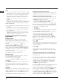
Cooking modes
! A temperature value can be set for all cooking modes
between 50°C and Max, except for
• GRILL, DOUBLE GRILL (recommended: set only to
MAX power level);
• GRATIN (recommended: do not exceed 200°C).
a TRADITIONAL OVEN mode
Both the top and bottom heating elements will come
on. When using this traditional cooking mode, it is best
to use one cooking rack only. If more than one rack is
used, the heat will be distributed in an uneven manner.
u BAKING mode
The rear heating element and the fan are switched
on, thus guaranteeing the distribution of heat in a
delicate and uniform manner throughout the entire
oven. This mode is ideal for baking and cooking
temperature sensitive foods (such as cakes that need
to rise) and for the preparation of pastries on 3 shelves
simultaneously.
w PIZZA mode
The circular heating elements and the elements at
the bottom of the oven are switched on and the fan is
activated. This combination heats the oven rapidly by
producing a considerable amount of heat, particularly
from the element at the bottom. If you use more than
one rack simultaneously, switch the position of the
dishes halfway through the cooking process.
b MULTI-COOKING mode
All the heating elements (top, bottom and circular)
switch on and the fan begins to operate. Since the heat
remains constant throughout the oven, the air cooks
and browns food in a uniform manner. A maximum of
two racks may be used at the same time.
d GRILL mode
The central part of the top heating element is switched
on. The high and direct temperature of the grill is
recommended for food that requires a high surface
temperature (veal and beef steaks, fillet steak and
entrecôte). This cooking mode uses a limited amount
of energy and is ideal for grilling Place the food in the
centre of the rack, as it will not be cooked properly if it
is placed in the corners.
2 DOUBLE GRILL mode
This provides a larger grill than the normal grill setting
and has an innovative design that improves cooking
efficiency by 50% and eliminates the cooler corner
areas. Use this grilling mode to achieve a uniform
browning on top of the food.
T GRATIN mode
The top heating element and the rotisserie (where
present) are activated and the fan begins to operate. This
combination of features increases the effectiveness of the
unidirectional thermal radiation provided by the heating
elements through forced circulation of the air throughout
the oven. This helps prevent food from burning on the
surface and allows the heat to penetrate right into the food.
! The GRILL, DOUBLE GRILL and GRATIN cooking
modes must be performed with the oven door shut.
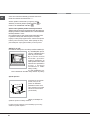
Rotisserie*
To operate the rotisserie proceed as follows:
1. Place the dripping pan in position
1.
2. Place the rotisserie support in
position 4 and insert the spit in the
hole provided on the back panel of
the oven (see gure).
3. Activate the rotisserie by selecting
2/T with the SELECTOR knob.
Lower oven compartment
There is a compartment underneath the oven that may
be used to storeoven accessories or deep dishes.
! Do not place flammable materials in the lower oven
compartment.
! The internal surfaces of the compartment (where
present) may become hot.
Practical cooking advice
! Do not place racks in position 1 or 5 during fan-
assisted cooking. Excessive direct heat can burn
temperature sensitive foods.
MULTI-COOKING
• Use positions 2 and 4, placing the food that requires
more heat on the rack in position 2.
• Place the dripping pan on the bottom and the rack on
top.

10
GB
* Only available in certain models.
GRILL
• When using the GRILL and DOUBLE GRILL cooking
modes, place the rack in position 5 and the dripping
pan in position 1 to collect cooking residues (fat
and/or grease). When using the GRATIN cooking
mode, place the rack in position 2 or 3 and the
dripping pan in position 1 to collect cooking
residues.
• We recommend that the power level is set to
maximum. The top heating element is regulated by a
thermostat and may not always operate contantly.
PIZZA OVEN MODE
• Use a light aluminium pizza pan. Place it on the rack
provided.
For a crispy crust, do not use the dripping pan as
it prevents the crust from forming by extending the
total cooking time.
• If the pizza has a lot of toppings, we recommend
adding the mozzarella cheese on top of the pizza
halfway through the cooking process.
Planning cooking with the electronic
programmer*
Setting the clock
After the appliance has been connected to the
power supply, or after a blackout, the display will
automatically reset to 0:00 and begin to blink. To set
the time:
1. Press the COOKING TIME button
$ and the
COOKING END TIME
% simultaneously.
2. Within 4 seconds of having pressed these buttons,
set the exact time by pressing the
* and ) buttons.
The
* button advances the hours and the ) button
decreases the hours.
Once the time has been set, the programmer
automatically switches to manual mode.
Setting the timer
The timer enables a countdown to be set, when the
time has elapsed a buzzer sounds.
To set the timer proceed as follows:
1. press the TIMER button
H. The display shows:
N.
2. Press the * and ) buttons to set the desired time.
3. When the buttons are released the timer begins
counting down and the current time appears on the
display.
R
4. After the time has elapsed a buzzer will sound, and
this can be switched off by pressing any button (except
the
* and ) buttons). The symbol H will switch off.
! The timer does not switch the oven on or off.
Adjusting the volume of the buzzer
After selecting and confirming the clock settings, use
the
) button to adjust the volume of the alarm buzzer.
Setting the cooking time with a delayed start
First decide which cooking mode you wish to use and
set a suitable temperature using the SELECTOR and
THERMOSTAT knobs on the oven.
At this point it is possible to set the cooking time:
1. Press the COOKING TIME button
$.
2. Within 4 seconds of having pressed this button, set
the desired amount of time by pressing the
* and )
buttons. If, for example, you wish to set a cooking time
of 30 minutes, the display will show:
N.
3. 4 seconds after the buttons are released, the current
time (for example 10.00) reappears on the display with
the symbol
m and the letter A (AUTO).
Next the desired cooking end time must be set:
4. Press the END COOKING TIME button
%.
5. Within 4 seconds of having pressed this button,
adjust the cooking end time by pressing the
* and
) buttons. If, for example, you want cooking to end at
13.00, the display shows:
O
6. 4 seconds after the buttons are released, the current
time (for example 10.00) reappears on the display with
the letter A (AUTO).
P
At this point, the oven is programmed to switch on
automatically at 12:30 and switch off after 30 minutes,
at 13.00.
Setting the cooking time with an immediate start
Follow the above procedure for setting the cooking
time (points 1-3).
! When the letter A appears, this indicates that both
the cooking time and the end cooking time have been
programmed in AUTO mode. To restore the oven to
manual operation, after each AUTO cooking mode
press the COOKING TIME
$ and END COOKING
TIME
% buttons simultaneously.
! The symbol
m will remain lit, along with the oven, for
the entire duration of the cooking programme.
The set cooking duration can be displayed at any time
by pressing the COOKING TIME button
$>$, and
the cooking end time may be displayed by pressing
the END COOKING TIME button
%. When the cooking
time has elapsed a buzzer sounds. To stop it, press
any button apart from the
* and ) buttons.

GB
11
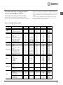
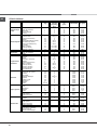
Oven cooking advice table
Cancelling a previously set cooking programme
Press the COOKING TIME button
$ and the
COOKING END TIME
% simultaneously.
Correcting or cancelling previously set data
The data entered can be changed at any time by
pressing the corresponding button (TIMER, COOKING
TIME or COOKING END TIME) and the
* or ) button.
When the cooking time data is cancelled, the cooking
end time data is also cancelled automatically, and vice
versa.
If the oven has already been programmed, it will not
accept cooking end times which are before the start of
the programmed cooking process.
Cooking
modes
Foods Weight
(in kg)
Rack position Preheating
time
(min)
Recommended
temperature
Cooking
time
(minutes)
Convection
Oven
Duck
Roast veal or beef
Roast pork
Biscuits (shortcrust pastry)
Tarts
1
1
1
-
1
3
3
3
3
3
15
15
15
15
15
200
200
200
180
180
65-75
70-75
70-80
15-20
30-35
Baking mode
Tarts
Fruit cakes
Sponge cake made with
yoghurt
Sponge cake
Stuffed pancakes (on 2 racks)
Small cakes (on 2 racks)
Cheese puffs (on 2 racks)
Cream puffs (on 3 racks)
Biscuits (on 3 racks)
Meringues (on 3 racks)
0.5
1
0.7
0.5
1.2
0.6
0.4
0.7
0.7
0.5
3
2 or 3
3
3
2 and 4
2 and 4
2 and 4
1 and 3 and 5
1 and 3 and 5
1 and 3 and 5
15
15
15
15
15
15
15
15
15
15
180
180
180
160
200
190
210
180
180
90
20-30
40-45
40-50
25-30
30-35
20-25
15-20
20-25
20-25
180
Pizza Mode
Pizza
Roast veal or beef
Chicken
0.5
1
1
3
2
2 or 3
15
10
10
220
220
180
15-20
25-30
60-70
Multi-cooking
Pizza (on 2 racks)
Lasagne
Lamb
Roast chicken + potatoes
Mackerel
Sponge cake made with
yoghurt
Cream puffs (on 2 racks)
Biscuits (on 2 racks)
Sponge cake (on 1 rack)
Sponge cake (on 2 racks)
Savoury pies
1
1
1
1+1
1
1
0.5
0.5
0.5
1
1.5
2 and 4
3
2
2 and 4
2
2
2 and 4
2 and 4
2
2 and 4
3
15
10
10
15
10
10
10
10
10
10
15
230
180
180
200
180
170
190
180
170
170
200
15-20
30-35
40-45
60-70
30-35
40-50
20-25
10-15
15-20
20-25
25-30
Grill
Sole and cuttlefish
Squid and prawn kebabs
Cuttlefish
Cod fillet
Grilled vegetables
Veal steak
Sausages
Hamburgers
Mackerel
Toasted sandwiches (or toast)
0.7
0.6
0.6
0.8
0.4
0.8
0.6
0.6
1
n.° 4 and 6
4
4
4
4
3 or 4
4
4
4
4
4
100%
100%
100%
100%
100%
100%
100%
100%
100%
100%
10-12
8-10
10-15
10-15
15-20
15-20
15-20
10-12
15-20
3-5
Veal steak
Cutlets
Hamburgers
Mackerel
Toast
1
1
1
1
n.° 4
4
4
4
4
4
5
5
5
5
5
Max
Max
Max
Max
Max
15-20
15-20
7-10
15-20
2-3
Double Grill
With the rotisserie
Spit-roast veal
Spit-roast chicken
1.0
2.0
5
5
Max
Max
70-80
70-80
Grilled chicken
Cuttlefish
1.5
1.5
2
2
10
10
200
200
55-60
30-35
With the rotisserie
Spit-roast veal
Spit-roast chicken
Spit-roast lamb
1.5
1.5
1.5
5
5
5
200
200
200
70-80
70-80
70-80
Gratin
With multi-spit rotisserie
(selected models only)
Meat kebabs
Vegetable kebabs
1.0
0.8
5
5
Max
Max
40-45
25-30

12
GB
Precautions and tips
! This appliance has been designed and manufactured
in compliance with international safety standards.
The following warnings are provided for safety reasons
and must be read carefully.
General safety
• The appliance was designed for domestic use inside
the home and is not intended for commercial or
industrial use.
• The appliance must not be installed outdoors, even in
covered areas. It is extremely dangerous to leave the
appliance exposed to rain and storms.
• Do not touch the appliance with bare feet or with wet
or damp hands and feet.
• The appliance must be used by adults only for
the preparation of food, in accordance with the
instructions provided in this booklet.
• The instruction booklet accompanies a class 1
(insulated) or class 2 - subclass 1 (recessed
between 2 cupboards) appliance.
• Keep children away from the oven.
• Make sure that the power supply cables of other
electrical appliances do not come into contact with
the hot parts of the oven.
• The openings used for the ventilation and dispersion
of heat must never be covered.
• Always use oven gloves when placing cookware in
the oven or when removing it.
• Do not use flammable liquids (alcohol, petrol, etc...)
near the appliance while it is in use.
• Do not place flammable material in the lower storage
compartment or in the oven itself. If the appliance is
switched on accidentally, it could catch fire.
• Always make sure the knobs are in the “
•” position
when the appliance is not in use.
• When unplugging the appliance, always pull the plug
from the mains socket; do not pull on the cable.
• Never perform any cleaning or maintenance work
without having disconnected the appliance from the
electricity mains.
• If the appliance breaks down, under no
circumstances should you attempt to repair
the appliance yourself. Repairs carried out by
inexperienced persons may cause injury or further
malfunctioning of the appliance. Contact Assistance.
• Do not rest heavy objects on the open oven door.
•
The appliance should not be operated by people
(including children) with reduced physical, sensory
or mental capacities, by inexperienced individuals
or by anyone who is not familiar with the product.
These individuals should, at the very least, be
supervised by someone who assumes responsibility
for their safety or receive preliminary instructions
relating to the operation of the appliance.
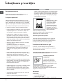
WARNING! The glass lid can break in
if it is heated up. Turn off all the burn-
ers and the electric plates before clos-
ing the lid
.
Disposal
• When disposing of packaging material: observe
local legislation so that the packaging may be
reused.
• The European Directive 2002/96/EC relating
to Waste Electrical and Electronic Equipment
(WEEE) states that household appliances should
not be disposed of using the normal solid urban
waste cycle. Exhausted appliances should be
collected separately in order to optimise the cost
of re-using and recycling the materials inside the
machine, while preventing potential damage to the
atmosphere and to public health. The crossed-out
dustbin is marked on all products to remind the
owner of their obligations regarding separated
waste collection. For more information relating to the
correct disposal of household appliances, owners
should contact their local authorities or appliance
dealer.
Respecting and conserving the
environment
• You can help to reduce the peak load of the
electricity supply network companies by using the
oven in the hours between late afternoon and the
early hours of the morning.
• Always keep the oven door closed when using the
GRILL and FAN-ASSISTED GRILL mode cooking.
This will achieve better results while saving energy
(approximately 10%).
• Check the door seals regularly and wipe them clean
to ensure they are free of debris so that they adhere
properly to the door, thus avoiding heat dispersion.

GB
13
Switching the appliance off
Disconnect your appliance from the electricity supply
before carrying out any work on it.
Cleaning the appliance
! Never use steam cleaners or pressure cleaners on
the appliance.
• The stainless steel or enamel-coated external parts
and the rubber seals may be cleaned using a
sponge that has been soaked in lukewarm water
and neutral soap. Use specialised products for the
removal of stubborn stains. After cleaning, rinse well
and dry thoroughly. Do not use abrasive powders or
corrosive substances.
• The hob grids, burner caps, flame spreader rings
and burners may be removed to make cleaning
easier; wash them in hot water and non-abrasive
detergent, making sure all burnt-on residue is
removed before drying them thoroughly.
• For hobs with electronic ignition, the terminal part of
the electronic lighting devices should be cleaned
frequently and the gas outlet holes should be
checked for blockages.
• The inside of the oven should ideally be cleaned
after each use, while it is still lukewarm. Use hot
water and detergent, then rinse well and dry with a
soft cloth. Do not use abrasive products.
•
Clean the glass part of the oven door using a
sponge and a non-abrasive cleaning product, then
dry thoroughly with a soft cloth. Do not use rough
abrasive material or sharp metal scrapers as these
could scratch the surface and cause the glass to
crack.
• The accessories can be washed like everyday
crockery, and are even dishwasher safe.
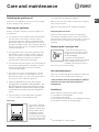
The cover*
If the cooker is fitted with
a glass cover, this cover
should be cleaned using
lukewarm water. Do not
use abrasive products.
It is possible to remove
the cover in order to make
cleaning the area behind
the hob easier. Open the
cover fully and pull it upwards (see gure).
! Do not close the cover when the burners are alight or
when they are still hot.
! Remove any liquid from the lid before opening it.
Inspecting the oven seals
Check the door seals around the oven regularly. If
the seals are damaged, please contact your nearest
Authorised After-sales Service Centre. We recommend
that the oven is not used until the seals have been
replaced.
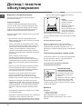
Replacing the oven light bulb
1. After disconnecting the oven
from the electricity mains, remove
the glass lid covering the lamp
socket (see gure).
2. Remove the light bulb and
replace it with a similar one: voltage
230 V, wattage 25 W, cap E 14.
3. Replace the lid and reconnect
the oven to the electricity supply.
Gas tap maintenance
Over time, the taps may become jammed or difficult to
turn. If this occurs, the tap must be replaced.
! This procedure must be performed by a qualified
technician who has been authorised by the
manufacturer.
Assistance
Please have the following information to hand:
• The appliance model (Mod.).
• The serial number (S/N).
This information can be found on the data plate located
on the appliance and/or on the packaging.
Care and maintenance
* Only available in certain models.

14
HU
! Fontos, hogy megtartsa ezt a kézikönyvet, hogy
szükség esetén bármikor belenézhessen. Ha a
készüléket eladja, elajándékozza vagy áthelyezi,
győződjön meg róla, hogy a kézikönyvet is átadja vele!
! Olvassa el fi gyelmesen az utasításokat: fontos
információkat tartalmaznak az üzembe helyezésről, a
használatról és a biztonságról.
! A készülék üzembe helyezését szakembernek kell
elvégeznie az itt található utasításoknak megfelelően.
! Bármilyen beállítási, karbantartási, stb. munkálatot
áramtalanított készüléken kell elvégezni.
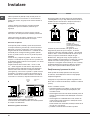
A helyiségek szellőzése
A készülék, az érvényben lévő nemzeti szabványoknak
megfelelően, kizárólag folyamatos szellőzéssel ellátott
helyiségekben helyezhető üzembe. A helyiségnek,
melyben a készüléket üzembe kívánja helyezni, annyi
levegőt kell tudnia biztosítani, amennyi a gáz tökéletes
égéséhez szükséges (a levegőáram az üzembe helyezett
teljesítmény 1 kW-jára vetítve nem lehet kevesebb 2 m
3
/h-
nál).
A levegő utánpótlását biztosító, ráccsal ellátott
szellőzőnyílásnak 100 cm
2
hasznos keresztmetszettel
kell rendelkeznie és úgy kell kialakítani, hogy még
részben se tömődhessen el (lásd A ábra).
Amennyiben a készülék munkalapja nincs
égésbiztosítóval ellátva, vagy a levegő közvetetten, a
fent leírtak szerint kialakított külső szellőzéssel ellátott
szomszédos helyiségekből érkezik (lásd B ábra) –
feltéve, hogy azok az ingatlannak nem közös részei,
környezetük nem tűzveszélyes, vagy nem hálószobák
– a szellőzőnyílások méretét 100%-os ráhagyással kell
kialakítani – legalább 200 cm
2
.
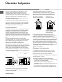
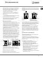
Szomszédos helyiség Szellőztetendő
helyiség
A B
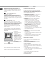
Az égést tápláló Az ajtó és padló közti
A füstgázelvezetést hatékony, természetes
huzatú kéménybe kötött kürtővel, vagy a készülék
bekapcsolásával automatikusan működésbe lépő
elektromos ventilátorral kell biztosítani (lásd ábra).
Közvetlenül a szabadba Kéményen vagy
történő füstgázelvezetés (tűzhelyekhez való)
Üzembe helyezés
A
levegő szellőzőnyílása rés növelése
! Amennyiben hosszú ideig használja a készüléket,
tanácsos kinyitni az ablakot, illetve megnövelni a
ventilátorok sebességét.
Füstgázelvezetés
elágazó füstgázelvezető
csövön keresztül történő
füstgázelvezetés
! A levegőnél nehezebb cseppfolyósított gázok
megülnek a padlószinten, ezért a cseppfolyósítottgáz-
tartályok tárolására szolgáló helyiségeknek, az
esetleges gázszivárgások elvezetésére, a padlószinten
rendelkezniük kell szabadba kivezető szellőzőnyílással.
Az üres vagy részben teli cseppfolyósítottgáz-tartályokat
tilos a padló szintjénél lejjebb lévő helyiségekben (pince,
stb.) üzembe helyezni vagy tárolni! A helyiségben kizárólag
a használatban lévő tartályt tárolja, távol azoktól a
hőforrásoktól (tűzhely, kandalló, kályha), melyek 50°C fölé
képesek azt melegíteni!
Elhelyezés és vízszintezés
! A készülék beépíthető bútorok mellé is, ha azok
magassága nem haladja meg a munkalap szintjét.
! Bizonyosodjon meg arról, hogy a készülék
hátoldalával érintkező fal nincs gyúlékony anyagból, és
ellenáll a hőnek (T 90°C)!
A készülék megfelelő beszerelése érdekében:
• helyezze a készüléket a konyhába, az étkezőbe vagy
a garzonba (ne a fürdőszobába);
• amennyiben a tűzhely szintje magasabb a
bútorokénál, azokat a készüléktől legalább 600 mm-re
kell elhelyezni;
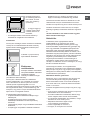
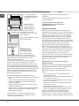
• amennyiben a tűzhelyet fali bútor alá szereli be, a
fali bútorok és a munkalap között legalább 420 mm

15
HU
távolságot kell hagyni.
Ez a távolság akár 700
mm is lehet, ha a fali
bútor nem gyúlékony
(lásd ábra);
• ne tegyen függönyt
a tűzhely mögé, illetve
a tűzhely 200 mm-es
körzetébe;
• az esetleges kürtőket a felhasználói kézikönyv
utasításainak megfelelően kell kialakítani.
Vízszintezés
Amennyiben szükséges, állítsa vízszintbe a készüléket,
csavarja be a mellékelt állítható lábazatot a tűzhely
aljának sarkain található megfelelő furatokba (lásd
ábra)!
A lábakat* nyomja a tűzhely
alján található illesztékbe!
Elektromos
csatlakoztatás
Szereljen a kábelre a készüléken
elhelyezett adattáblán feltüntetett
terhelésnek megfelelő
szabványos csatlakozó dugót
(lásd Műszaki adatok táblázat)!
Amennyiben a kábelt közvetlenül a hálózathoz
kívánja csatlakoztatni, úgy a készülék és a hálózat
közé a terhelésnek és az érvényben lévő nemzeti
szabványoknak megfelelő legalább 3 mm-es
omnipoláris kapcsolót kell beszerelni (a föld huzalt nem
kell megszakítóval ellátni). A hálózati kábelt úgy kell
elhelyezni, hogy sehol ne érjen szobahőmérséklethez
képest 50°C-nál magasabb részhez.
A csatlakoztatás előtt ellenőrizze, hogy:
• az aljzat rendelkezzen földeléssel és feleljen meg a
szabványnak;
• az aljzat képes legyen elviselni a készülék
adattábláján feltüntetett maximális teljesítmény
terhelését;
• a tápfeszültség feleljen meg az adattáblán feltüntetett
értékeknek;
• az aljzat legyen kompatíbilis a készülék csatlakozó
HOOD
420
Min.
min.
650
mm. with hood
min.
700
mm. without hood
mm.
600
Min. mm.
420
Min. mm.
dugójával! Ha nem, cserélje ki az aljzatot vagy a
dugót; ne használjon hosszabbítót vagy elosztót!
! A beszerelt készülék elektromos kábelének és a fali
csatlakozónak könnyen hozzáférhetőnek kell lennie.
! A kábel nem hajolhat meg és nem lehet összenyomva!
! A kábelt rendszeresen ellenőrizni kell, és cseréjét
kizárólag engedéllyel rendelkező szakember végezheti
el.
! A fenti előírások be nem tartása esetén a gyártó
elhárít minden felelősséget.
Gázbekötés
A hálózathoz, illetve a gázpalackhoz történő
csatlakoztatáshoz, az érvényben lévő nemzeti
szabványoknak megfelelően, fl exibilis gumicső vagy
acélcső használtató. A gázbekötés után győződjön meg
arról, hogy a készülék a szolgáltatott gáz típusára lett
állítva (lásd a tetőn elhelyezett gázkalibrálási címkét):
ellenkező esetbenlásd alább)! Abban az esetben, ha a
készüléket cseppfolyósított gázzal, palackról működteti,
használjon az érvényben lévő nemzeti szabványoknak
megfelelő nyomásszabályozót! A csatlakoztatás
megkönnyítése érdekében a használandó gáz a
készülékhez mindkét oldala* felől hozzávezethető:
cserélje le a csatlakozó csonkot a záródugóra, és a régi
tömítést a mellékelt tömítésre!
! A biztonságos működés, az energiatakarékos
használat és a készülék hosszú élettartama érdekében,
bizonyosodjon meg arról, hogy a tápnyomás megfelel a
Gázégők és a fúvókák jellemző adatai című táblázatban
közölt értékeknek (lásd alább)!
Gázbekötés fl exibilis gumicsővel
Ellenőrizze, hogy a cső megfelel-e az érvényben lévő
nemzeti szabványoknak! Cseppfolyósított gázzal
történő üzemeltetés esetén a cső belső átmérőjének
8 cm-esnek kell lennie, metánnal történő üzemeltetés
esetén 13 cm-esnek.
A bekötés elvégeztével bizonyosodjon meg arról, hogy
a cső:
• egyik pontja se érintkezik olyan elemmel, melynek a
hőmérséklete 50°C fölé emelkedhet;
• nincs kitéve húzásnak és csavarásnak, valamint, hogy
nincsen megtörve, illetve nincsen benne szűkület;
• nem érintkezik vágófelülettel, éles szélekkel, mozgó
elemekkel és nincs összenyomva;
• állapotának ellenőrzése végett a teljes
nyomvonalában jól hozzáférhető
;
• hossza meghaladja az 1500 mm-t;
• két végén, az érvényben lévő nemzeti

16
HU
szabványoknak megfelelően, csőbilinccsel jól fel van
rögzítve!
! Amennyiben a fenti feltételek közül egy vagy több
feltétel nem teljesülhet, vagy ha a tűzhelyet a 2.
osztály – 1. alosztály előírásai szerint helyezi üzembe
(a készülék két bútor közé kerül), a bekötést fl exibilis
acélcsővel kell megoldani (lásd alább).
Gázbekötés nem oxidálódó, folyamatos falú,
menetes végű, fl exibilis acélcsővel
Ellenőrizze, hogy a cső és a tömítések megfelelnek-e
az érvényben lévő nemzeti szabványoknak!
A cső bekötéséhez távolítsa el a készüléken található
csonkot (a készülék gázbemeneti csatlakozása 1/2”-os
anyamenettel van ellátva)!
! Kösse be a csövet olyan módon, hogy a cső hossza
ne haladja meg a maximálisan megengedett 2 métert,
és bizonyosodjon meg arról, hogy a cső nem érintkezik
mozgó elemekkel, és nincs összenyomva!
A tömítés ellenőrzése
A bekötés végeztével szappanos vízzel – semmiképp
se lánggal – ellenőrizze, hogy valamennyi csatlakozás
tömítése tökéletesen zár-e!
Átállítás más gáztípusra
A készülék átállítható az eredetileg beállítottól – a
tűzhely tetején található gázkalibrálási címkén jelzett
gáztól – eltérő gáztípusra is.
A főzőlap átállítása
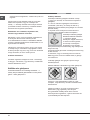
A főzőlapon található gázégők fúvókáinak cseréje:
1. vegye le a rácsokat, és csavarozza ki helyükről a
gázégőket;
2. 7 mm-es csőkulcs segítségével csavarozza ki
a fúvókákat ( lásd ábra), és cserélje le őket az új
gáztípushoz való fúvókákra (lásd gázégők és a fúvókák
jellemző adatai);
3. helyezze vissza a helyére az összes elemet a
fentiekben leírt műveletek fordított sorrendjében!
A főzőlapon található gázégők
takarékfokozatának beállítása:
1. csavarja a gázégő
szabályozó csapját minimumra;
2. húzza le a tekerőgombot,
és csavarja a tekerőgomb
tengelyében vagy amellett
elhelyezett szabályozócsavart addig, míg szabályos kis
lángot nem kap!
! Cseppfolyósított gáz esetén a szabályozócsavart tövig
be kell csavarni;
3. ellenőrizze, hogy ha a tekerőgombot a maximum
állásból gyorsan a minimum állásba tekeri, a gázégő
nem alszik-e ki!
! A főzőlap gázégői nem igénylik a primer levegő
beszabályozását.
! Miután átállította a készüléket egy másik gáztípusra,
cserélje le a régi gázkalibrálási címkét az új gáz
címkéjére, mely valamennyi hivatalos szakszervizben
beszerezhető!
! Abban az esetben, ha a gáz nyomása az előírt
értéktől eltér (vagy ingadozik), az érvényben
lévő, gázhálózati szabályozókról szóló nemzeti
szabványoknak megfelelően, a gázcs
ő bemenete elé
nyomásszabályozót kell beépíteni.

17
HU
S
S
R
A
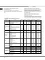
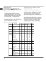
A gázégők és a fúvókák jellemző adatai
KN3G76SA/UA
1. táblázat
G 20 G 30
Gázégő
Átmérő
(mm)
Gyújtóláng,
1/100 (mm)
Csökkent
ett
hőenergia
, kW
Fúvóka,
1/100
(mm)
Névleges
hőenergia,
kW
Átáramlás*
l/h
Fúvóka,
1/100
(mm)
Névleges
hőenergia,
kW
Átáramlás*
g/h
Gyors (R)
100 41 0.80 128 3.30 314 87 3.00 218
Fél-gyors (S)
75 30 0.50 104 2.10 200 70 1.90 138
Kisegítő (A)
51 30 0.50 76 1.15 109 52 1.00 73
Hálózati
nyomás
Nom.
Min.
Max
25
20
30
30
25
35
15°C-on és 1013 mbar-nál
P.C.S. G20 37,78 MJ/m
3
P.C.S. G30 49,47 MJ/kg
ADATTÁBLÁZAT
Méretek
Szélesség: 41 cm
Magasság: 34 cm
Mélység: 39 cm
Térfogat
54 l
Az ételmelegítő rész
hasznos méretei
Szélesség: 42 cm
Magasság: 23 cm
Mélység: 44 cm
A hálózati áram
feszültsége és
frekvenciája
Lásd az adattáblán.
ENERGIAOSZTÁLY
A villamos sütők energiafogyasztási
címkézéséről szóló 2002/40/EK
irányelv.
EN 50304 szabvány
Természetes hőáramlás névleges
energiafogyasztása – melegítő funkció:
Hagyományos
Kényszer hőáramlási osztály névleges
energiafogyasztása – melegítő funkció:
Süteménysütés
A készülék megfelel az alábbi uniós
irányelveknek: 2006.12.12-i
2006/95/EGK irányelv (alacsony
feszültség) és annak módosításai –
2004.12.15-i 04/108/EGK irányelv
(elektromágneses összeférhetőség) és
annak módosításai – 1993.07.22-i
93/68/EGK irányelv és annak
módosításai.
2006/96/EGK
1275/2008 (Stand-by/Off mode)

18
HU
Bekapcsolás és használat
A főzőlap használata
Az égőfej meggyújtása
A GÁZÉGŐ tekerőgombok esetében a gombhoz tartozó
gázégőt tele kör jelzi.
A főzőlap tetszőleges gázégőjének meggyújtása:
1. közelítsen egy gyufát vagy gázgyújtót a gázégőhöz;
2. nyomja be, és ezzel egyidejűleg csavarja a GÁZÉGŐ
tekerőgombját órairánnyal ellentétesen a nagy láng
szimbólumra E;
3. a láng kívánt erősségének beállításához csavarja
a GÁZÉGŐ tekerőgombját órairánnyal ellentétesen
takarékra C, nagy lángra E vagy egy köztes állásba!
Amennyiben a készülék elektromos gyújtással*
rendelkezik (lásd ábra),
elegendő, ha benyomja, és
ezzel egyidejűleg, órairánnyal
ellentétesen elcsavarja a
GÁZÉGŐ tekerőgombját a
takarékláng szimbólumra,
míg a láng meg nem gyullad.
Előfordulhat, hogy a gázégő
kialszik, ha a gombot elengedi. Ilyenkor ismételje meg
a fenti műveletet úgy, hogy a tekerőgombot hosszabb
ideig tartja benyomva!
! Abban az esetben, ha a láng véletlenül kialudna, zárja
el a gázégőt, és mielőtt újra meggyújtaná, várjon 1
percet!
Amennyiben a készülék égésbiztosítóval* rendelkezik,
tartsa a GÁZÉGŐ tekerőgombját nagyjából 2-3
másodpercre lenyomva annak érdekében, hogy a láng
égve maradjon és az égésbiztosító bekapcsoljon!
A gázégő kikapcsolásához csavarja a tekerőgombot
ütközésig a • jelig!
A gázégők használatával kapcsolatos praktikus
tanácsok
A gázégők optimális teljesítménye és az alacsony
gázfogyasztás érdekében a gázég
ő méretéhez illő,
fedővel ellátott lapos fenekű edényeket érdemes
használni.
A gázégők típusának megállapításához tekintse meg a
„A gázégők és a fúvókák jellemző adatai” fejezet rajzait.
A sütő használata
! Első bekapcsoláskor működtesse a sütőt üresen
legalább egy óra hosszat maximumra állított
termosztáttal és csukott ajtó mellett! Ezután kapcsolja
ki a sütőt, nyissa ki az ajtaját, és szellőztesse ki a
helyiséget! A keletkezett szag a sütő védelmére
használt anyagok elpárolgásából származik.
! Soha ne támasszon semmit a sütő aljának, mert a
zománc megsérülhet!
! Használatbavétel előtt gondosan húzza le a készülék
oldalaira felragasztott műanyag fi lmrétegeket!
1. A PROGRAMVÁLASZTÓ tekerőgomb elforgatásával
válassza ki a kívánt sütési programot!
2. A HŐFOKSZABÁLYOZÓ tekerőgombbal válassza ki
a programhoz ajánlott, vagy a kívánt hőmérséklet!
A vonatkozó táblázatban kikereshetők az ajánlott sütési
módok és az azokhoz tartozó javasolt hőmérsékletek
(lásd Sütési táblázat).
Sütés alatt mindig megteheti az alábbiakat:
• módosíthatja a sütési programot a
PROGRAMVÁLASZTÓ tekerőgomb segítségével;
• módosíthatja a hőmérsékletet a
HŐFOKSZABÁLYOZÓ tekerőgomb segítségével;
• megszakíthatja a sütést a PROGRAMVÁLASZTÓ
tekerőgomb „0” helyzetbe állításával.
! A sütőedényeket mindig a mellékelt rácsokra tegye!
TERMOSZTÁT ellenőrzőlámpa
Ha ég, az azt jelenti, hogy a sütő hőt termel. A lámpa
akkor alszik ki, ha a sütő belsejében a hőmérséklete
eléri a kívánt értéket. A questo punto la spia si
accende e si spegne alternativamente, indicando che
il termostato e in funzione e mantiene costante la
temperatura.
SÜTŐ ÜZEMÁLLAPOT-JELZŐ lámpa
Ha ég, az azt jelenti, hogy a sütő be van kapcsolva.
* Csak néhány modellnél.
! A kis edénytartó ráccsal rendelkező modelleknél a
rács kizárólag a kiegészítő gázégőhöz használható, és
12 cm-nél kisebb átmérőjű edények melegíthetők rajta.
X
C
Égő
Az edény átmérője (cm)
Gyors (R) 24-26
Közepes égő (S) 16-20
Segédégő (A) 10-14

19
HU
* Csak néhány modellnél.
Sütővilágítás
Amennyiben a PROGRAMVÁLASZTÓ tekerőgombot
egy, a „0”-tól eltérő helyzetbe forgatja, a sütővilágítás
kigyullad. A világítás a sütő működése során
bekapcsolva marad. Ha a tekerőgombot a
8-as
állásba kapcsolja, a lámpa kigyullad, azonban melegítő
funkció nem lép működésbe.
Sütési programok
HAGYOMÁNYOS SÜTÉS
Hőmérséklet: igény szerint 50 °C és a maximális érték
között.
A két alsó és felső fűtőszál bekapcsol. Ennél a
hagyományos sütési módnál inkább csak egy szintet
használjon: ha több szinten süt, a hőeloszlás nem
megfelelő.
SÜTEMÉNYSÜTÉS program
Hőmérséklet: igény szerint 50 °C és a maximális érték
között.
Bekapcsol az alsó fűtőszál és működni kezd a
ventilátor, fi nom és egyenletes hőeloszlást biztosítva
a sütő belsejében. Ez a program kíméletes sütést
igénylő ételek (például kelt tészták) sütéséhez, valamint
egyszerre három szinten „mignon” elkészítéséhez
javasolt.
PIZZASÜTÉS program
Hőmérséklet: igény szerint 50 °C és a maximális érték
között.
Bekapcsol az alsó és a körkörös fűtőszál és a ventilátor
működni kezd. Ez a kombináció lehetővé teszi a
sütő gyors felmelegedését, elsősorban alulról érkező
erőteljes hőárammal. Ha egyszerre egynél több szintet
használ, a sütésidő felénél cserélje meg a tepsik helyét.
LÉGKEVERÉSES SÜTÉS program
Hőmérséklet: igény szerint 50 °C és a maximális érték
között.
Az összes fűtőszál bekapcsol (felső, alsó és körkörös),
és a ventilátor működni kezd. Mivel a hő az egész
sütőben állandó, a levegő egyenletesen süti és
pirítja az ételt. Egyidejűleg maximum két szintet lehet
használni.
GRILLEZÉS program
Hőmérséklet: maximum.
Bekapcsol a felső középső fűtőszál. A grillezés
magasabb és közvetlen hőmérséklete olyan
A sütő használata
! Első bekapcsoláskor működtesse a sütőt üresen
legalább egy óra hosszat maximum hőmérsékleti
fokozaton és csukott ajtó mellett. Ezután kapcsolja
ki a sütőt, nyissa ki az ajtaját, és szellőztesse ki a
helyiséget. A keletkezett szag a sütő védelmére
használt anyagok elpárolgásából származik.
! Használatbavétel előtt gondosan húzza le a készülék
oldalaira felragasztott műanyag fi lmrétegeket.
! Soha ne támasszon semmit közvetlenül a sütő
aljának, mert a zománc megsérülhet.
! Az elektromos programozóval* ellátott készülékeknél
az elektromos sütő használatához a sütési mód
kiválasztása előtt nyomja meg egyidejűleg a
és
gombot (a kijelzőn megjelenik a szimbólum).
1. A PROGRAMVÁLASZTÓ tekerőgomb elforgatásával
válassza ki a kívánt sütési programot.
2. A HŐMÉRSÉKLET-SZABÁLYZÓ tekerőgombbal
válassza ki a programhoz ajánlott, vagy a kívánt
hőmérséklet.
A vonatkozó táblázatban kikereshetők az ajánlott sütési
módok és az azokhoz tartozó javasolt hőmérsékletek
(lásd Sütési táblázat).
Sütés alatt a következőket mindig megteheti:
• A PROGRAMVÁLASZTÓ tekerőgomb segítségével
módosíthatja a sütési programot.
• A HŐMÉRSÉKLET-SZABÁLYZÓ tekerőgomb
segítségével módosíthatja a hőmérsékletet.
• A PROGRAMVÁLASZTÓ tekerőgomb „0” helyzetbe
állításával megszakíthatja a sütést.
! A sütőedényeket mindig a mellékelt rácsokra tegye.
HŐMÉRSÉKLET-SZABÁLYZÓ ellenőrzőlámpa
Ha ég, a sütő be van kapcsolva. A lámpa akkor alszik
ki, ha a sütő belsejében a hőmérséklet eléri a kívánt
értéket. Ekkor a lámpa váltakozva kigyullad és kialszik,
jelezve, hogy a hőmérséklet-szabályzó

20
HU
ételekhez javasolt, melyek magasabb felületi
hőmérsékletet igényelnek (borjú- és marhasült, fi lé,
rostélyos). A program ideális grillezéséhez. Helyezze
az ételt a rács közepére, mert a sarkokban nem fog
megsülni.
DUPLA GRILLEZÉS program
Hőmérséklet: maximum.
A szokásosnál nagyobb és innovatív kiképzéssel
rendelkező grill a sütés hatásfokát 50%-kal növeli, és
lehetővé teszi, hogy a sarkokba is eljusson a hő. Akkor
használja ezt a grillezési módot, ha egyenletes pirulást
kíván elérni.
GRATINÍROZÁS program
Hőmérséklet: igény szerint 50 °C és 200 °C között.
Bekapcsol a felső fűtőszál és működni kezd a ventilátor
és a forgónyárs (ha van). Ez a sütési mód a sütő
belsejében egyesíti a levegő keringtetését az egyirányú
hősugárzással. Ez a hő áthatolóképességének
növelésével segíti megakadályozni, hogy az ételek
felülete megégjen.
! A GRILLEZÉSHEZ, a DUPLA GRILLEZÉSHEZ és
GRATINÍROZÁSHOZ a sütőajtónak zárva kell lennie.
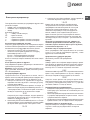
Lacikonyha
A forgónyárs
használatához tegye a
következőket:
1. Tegye a zsírfelfogó
tálcát az 1. szintre.
2. Helyezze a forgónyárs
támasztékát a 4. szintre,
és rakja be a nyársat a
sütő hátsó falán található
megfelelő furatba (lásd
ábra).
3. A forgónyárs
elindításához a PROGRAMVÁLASZTÓ tekerőgombbal
válassza ki a
programot.
! Az alsó tárolótérbe ne tegyen gyúlékony anyagot:
! A fi ók (ha van) belső felületei felmelegedhetnek.
Praktikus sütési tanácsok
! Légkeveréses sütésnél ne használja a sütő aljától
számított 1. és 5. szintet: ezeket a helyeket közvetlenül
éri a meleg levegő, ami a kíméletes sütést igénylő
ételek odaégését eredményezheti.
LÉGKEVERÉSES ÜZEMMÓD
• Használja a 2. és a 4. szintet. A 2. szintre tegye a
magasabb hőmérsékletet igénylő ételeket.
• Helyezze a zsírfelfogó tálcát alulra, a rácsot felülre.
GRILLEZÉS
• GRILLEZÉSKOR és DUPLA GRILLEZÉSKOR
helyezze a rácsot az 5. szintre, a sütési
melléktermékek (szaft és/vagy zsír) felfogása
érdekében pedig helyezze a zsírfelfogó tálcát az
1. szintre. GRATINÍROZÁSKOR helyezze a rácsot
a 2-es vagy 3-as szintre, a sütési melléktermékek
felfogása érdekében pedig helyezze a zsírfelfogó
tálcát az 1-es szintre.
• Javasoljuk, hogy a hőmérsékletet állítsa a
legmagasabb fokozatra. A felső fűtőszálat
hőmérséklet-szabályzó vezérli, így előfordulhat, hogy
nem működik folyamatosan.
PIZZASÜTÉS
• Használjon könnyű, alumínium tepsit a mellékelt
rácsra helyezve.
A zsírfelfogó tálcával elhúzódik a sütési idő és nehéz
ropogós pizzát kapni.
• Sok feltétet tartalmazó pizzáknál javasoljuk, hogy a
mozzarellát a sütés felénél tegye a tésztára.
Elektronikus időzítés*
Lehetővé teszi az óra és a visszaszámláló funkció
megjelenítését.
! Minden funkció a beállítását követően körülbelül
7 másodperc elteltével aktiválódik.
Az óra visszaállítása
A készülék hálózathoz való csatlakoztatásakor, illetve
áramkimaradást követően a kijelzőn az alábbi felirat fog
villogni: 0:00
• Az óra beállításához nyomja meg a
v és a -
gombot, majd a
+ gombot. A gyors beállításhoz tartsa
benyomva a gombokat.
Az óra esetleges átállításához ismételje meg a
fentiekben leírt lépéseket.
Percszámláló funkció
Pagina se încarcă...
Pagina se încarcă...
Pagina se încarcă...
Pagina se încarcă...
Pagina se încarcă...
Pagina se încarcă...
Pagina se încarcă...
Pagina se încarcă...
Pagina se încarcă...
Pagina se încarcă...
Pagina se încarcă...
Pagina se încarcă...
Pagina se încarcă...
Pagina se încarcă...
Pagina se încarcă...
Pagina se încarcă...
Pagina se încarcă...
Pagina se încarcă...
Pagina se încarcă...
Pagina se încarcă...
Pagina se încarcă...
Pagina se încarcă...
Pagina se încarcă...
Pagina se încarcă...
Pagina se încarcă...
Pagina se încarcă...
Pagina se încarcă...
Pagina se încarcă...
Pagina se încarcă...
Pagina se încarcă...
Pagina se încarcă...
Pagina se încarcă...
Pagina se încarcă...
Pagina se încarcă...
Pagina se încarcă...
Pagina se încarcă...
Pagina se încarcă...
Pagina se încarcă...
Pagina se încarcă...
Pagina se încarcă...
Pagina se încarcă...
Pagina se încarcă...
Pagina se încarcă...
Pagina se încarcă...
Pagina se încarcă...
Pagina se încarcă...
Pagina se încarcă...
Pagina se încarcă...
-
 1
1
-
 2
2
-
 3
3
-
 4
4
-
 5
5
-
 6
6
-
 7
7
-
 8
8
-
 9
9
-
 10
10
-
 11
11
-
 12
12
-
 13
13
-
 14
14
-
 15
15
-
 16
16
-
 17
17
-
 18
18
-
 19
19
-
 20
20
-
 21
21
-
 22
22
-
 23
23
-
 24
24
-
 25
25
-
 26
26
-
 27
27
-
 28
28
-
 29
29
-
 30
30
-
 31
31
-
 32
32
-
 33
33
-
 34
34
-
 35
35
-
 36
36
-
 37
37
-
 38
38
-
 39
39
-
 40
40
-
 41
41
-
 42
42
-
 43
43
-
 44
44
-
 45
45
-
 46
46
-
 47
47
-
 48
48
-
 49
49
-
 50
50
-
 51
51
-
 52
52
-
 53
53
-
 54
54
-
 55
55
-
 56
56
-
 57
57
-
 58
58
-
 59
59
-
 60
60
-
 61
61
-
 62
62
-
 63
63
-
 64
64
-
 65
65
-
 66
66
-
 67
67
-
 68
68


Whirlpool KN3G76SA(X)/UA Manualul utilizatorului
- Categorie
- Microunde
- Tip
- Manualul utilizatorului
în alte limbi
- slovenčina: Whirlpool KN3G76SA(X)/UA Užívateľská príručka