Yamaha RX-797 Manualul proprietarului
- Categorie
- CD playere
- Tip
- Manualul proprietarului

YAMAHA ELECTRONICS CORPORATION, USA
6660 ORANGETHORPE AVE., BUENA PARK, CALIF. 90620, U.S.A.
YAMAHA CANADA MUSIC LTD.
135 MILNER AVE., SCARBOROUGH, ONTARIO M1S 3R1, CANADA
YAMAHA ELECTRONIK EUROPA G.m.b.H.
SIEMENSSTR. 22-34, 25462 RELLINGEN BEI HAMBURG, GERMANY
YAMAHA ELECTRONIQUE FRANCE S.A.
RUE AMBROISE CROIZAT BP70 CROISSY-BEAUBOURG 77312 MARNE-LA-VALLEE CEDEX02, FRANCE
YAMAHA ELECTRONICS (UK) LTD.
YAMAHA HOUSE, 200 RICKMANSWORTH ROAD WATFORD, HERTS WD18 7GQ, ENGLAND
YAMAHA SCANDINAVIA A.B.
J A WETTERGRENS GATA 1, BOX 30053, 400 43 VÄSTRA FRÖLUNDA, SWEDEN
YAMAHA MUSIC AUSTRALIA PTY, LTD.
17-33 MARKET ST., SOUTH MELBOURNE, 3205 VIC., AUSTRALIA
©
2005 All rights reserved.
RX-797
Printed in Malaysia WG05000
RX-797
Stereo Receiver
Récepteur stéréo
OWNER’S MANUAL
MODE D’EMPLOI
BEDIENUNGSANLEITUNG
BRUKSANVISNING
GEBRUIKSAANWIJZING
ИНСТРУКЦИЯ ПО ЭКСПЛУАТАЦИИ
G
01EN_RX-797_G-cv.fm Page 1 Tuesday, August 30, 2005 4:06 PM

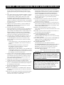
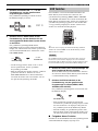
CAUTION: READ THIS BEFORE OPERATING YOUR UNIT.
1 To assure the finest performance, please read this manual
carefully. Keep it in a safe place for future reference.
2 Install this sound system in a well ventilated, cool, dry, clean
place – away from direct sunlight, heat sources, vibration,
dust, moisture, and/or cold. Allow ventilation space of at least
30 cm on the top, 20 cm on the left and right, and 20 cm on
the back of this unit.
3 Locate this unit away from other electrical appliances, motors,
or transformers to avoid humming sounds.
4 Do not expose this unit to sudden temperature changes from
cold to hot, and do not locate this unit in an environment with
high humidity (i.e. a room with a humidifier) to prevent
condensation inside this unit, which may cause an electrical
shock, fire, damage to this unit, and/or personal injury.
5 Avoid installing this unit where foreign objects may fall onto
this unit and/or this unit may be exposed to liquid dripping or
splashing. On the top of this unit, do not place:
– Other components, as they may cause damage and/or
discoloration on the surface of this unit.
– Burning objects (i.e. candles), as they may cause fire,
damage to this unit, and/or personal injury.
– Containers with liquid in them, as they may fall and liquid
may cause electrical shock to the user and/or damage to
this unit.
6 Do not cover this unit with a newspaper, tablecloth, curtain,
etc. in order not to obstruct heat radiation. If the temperature
inside this unit rises, it may cause fire, damage to this unit,
and/or personal injury.
7 Do not plug in this unit to a wall outlet until all connections
are complete.
8 Do not operate this unit upside-down. It may overheat,
possibly causing damage.
9 Do not use force on switches, knobs and/or cords.
10 When disconnecting the power cable from the wall outlet,
grasp the plug; do not pull the cable.
11 Do not clean this unit with chemical solvents; this might
damage the finish. Use a clean, dry cloth.
12 Only voltage specified on this unit must be used. Using this
unit with a higher voltage than specified is dangerous and may
cause fire, damage to this unit, and/or personal injury.
YAMAHA will not be held responsible for any damage
resulting from use of this unit with a voltage other than
specified.
13 To prevent damage by lightning, keep the power cord and
outdoor antennas disconnected from a wall outlet or the unit
during a lightning storm.
14 Do not attempt to modify or fix this unit. Contact qualified
YAMAHA service personnel when any service is needed. The
cabinet should never be opened for any reasons.
15 When not planning to use this unit for long periods of time
(i.e. vacation), disconnect the AC power plug from the wall
outlet.
16 Install this unit near the AC outlet and where the AC power
plug can be reached easily.
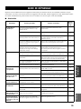
17 Be sure to read the “TROUBLESHOOTING” section on
common operating errors before concluding that this unit is
faulty.
18 Before moving this unit, press MASTER ON/OFF to release it
outward to the OFF position, and disconnect the AC power
plug from the wall outlet.
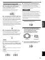
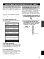
19 VOLTAGE SELECTOR (Asia and General models only)
The VOLTAGE SELECTOR on the rear panel of this unit
must be set for your local main voltage BEFORE plugging
into the AC main supply. Voltages are:
General model.............AC 110/120/220/230–240 V, 50/60 Hz
Asia model ................................AC 220/230–240 V, 50/60 Hz
\
CAUTION: READ THIS BEFORE OPERATING YOUR UNIT.
WARNING
TO REDUCE THE RISK OF FIRE OR ELECTRIC
SHOCK, DO NOT EXPOSE THIS UNIT TO RAIN
OR MOISTURE.
As long as this unit is connected to the AC wall outlet,
it is not disconnected from the AC power source even
if you turn off this unit by MASTER ON/OFF, or
MAIN ZONE ON/OFF and ZONE 2 ON/OFF. In this
state, this unit is designed to consume a very small
quantity of power.

1
PREPARATIONINTRODUCTION
BASIC
OPERATION
ADDITIONAL
INFORMATION
ADVANCED
OPERATION
English
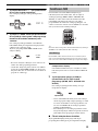
FEATURES............................................................. 2
SUPPLIED ACCESSORIES ................................. 2
CONTROLS AND FUNCTIONS ......................... 3
Front panel ................................................................. 3
Front panel display .................................................... 5
Rear panel .................................................................. 6
Remote control........................................................... 7
Zone 2 remote control................................................ 9
Installing batteries in the remote controls................ 10
Using the remote controls........................................ 10
CONNECTIONS .................................................. 11
Connecting speakers ................................................ 11
Connecting audio and video components................ 12
Connecting the AM and FM antennas ..................... 13
Connecting the power supply cord .......................... 15
Turning on and off this unit..................................... 16
PLAYING AND RECORDING .......................... 17
Playing a source....................................................... 17
Adjusting the tonal quality....................................... 19
Recording a source .................................................. 20
Using the sleep timer ............................................... 21
Muting the sound output.......................................... 22
FM/AM TUNING ................................................. 23
Automatic tuning ..................................................... 23
Manual tuning.......................................................... 24
Automatic preset tuning........................................... 25
Manual preset tuning ............................................... 27
Selecting preset stations........................................... 28
Exchanging preset stations ...................................... 28
RADIO DATA SYSTEM
(EUROPE MODEL ONLY) ............................ 29
Receiving Radio Data System stations.................... 29
Changing the Radio Data System mode .................. 29
PTY SEEK function ................................................ 30
EON function........................................................... 31
ADVANCED SETUP............................................32
Changing the ADVANCED SETUP menu
parameters ........................................................... 32
Switching the remote control ID ............................. 33
ZONE 2 ..................................................................34
Connecting the Zone 2 components ........................ 34
Controlling Zone 2................................................... 35
REMOTE CONTROL FEATURES ...................36
Control area ............................................................. 36
Controlling other components ................................. 37
Setting remote control codes ................................... 38
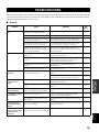
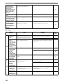
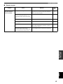
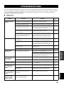
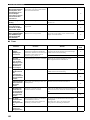
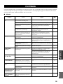
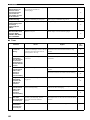
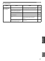
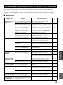
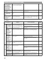
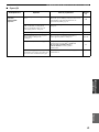
TROUBLESHOOTING .......................................39
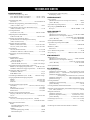
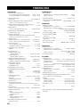
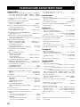
SPECIFICATIONS...............................................42
CONTENTS
INTRODUCTION
PREPARATION
BASIC OPERATION
ADVANCED OPERATION
ADDITIONAL INFORMATION

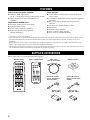
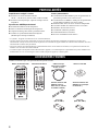
FEATURES
2
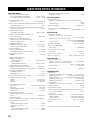
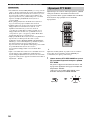
Built-in 2-channel power amplifier
◆ Minimum RMS output power
100 W + 100 W (8 Ω), 0.019% THD, 20 Hz to 20 kHz
◆ Highly dynamic power, low impedance drive
capability
Sophisticated AM/FM tuner
◆ 40-station random access preset tuning
◆ Automatic preset tuning
◆ Preset station exchanging capability
◆ Radio Data System tuning capability
(Europe model only)
Other features
◆ PURE DIRECT button used to reproduce the purest
source sound
◆ CD DIRECT AMP button used to reproduce the purest
CD sound
◆ REC OUT selector independent of input source
selection
◆ Continuously variable loudness control
◆ Sleep timer
◆ Remote control capability
◆ Zone 2 remote control supplied
◆ Zone 2 custom installation facility
• y indicates a tip for your operation.
• Some operations can be performed by using either the buttons on the front panel of this unit or those on the remote controls. In case
the button names differ between this unit and the remote controls, the names of the buttons on the remote controls are given in
parentheses.
• In case the buttons on the remote control and the Zone 2 remote control have certain functions in common, the illustrations of the
buttons on the remote control are used for explanation throughout the manual.
• This manual is printed prior to production. Design and specifications are subject to change in part as a result of improvements, etc. In
case of differences between the manual and the product, the product has priority.
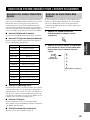
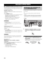
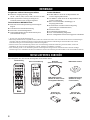
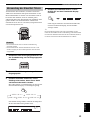
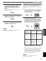
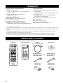
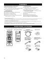
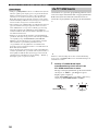
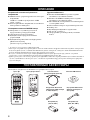
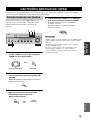
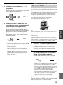
Please check that you received all of the following parts.
FEATURES
SUPPLIED ACCESSORIES
CD PHONO
ZONE 2
TUNER
MD/TAPE VCR DTV/CBL
DVD
POWER
STANDBY
+
–
u
d
REC
DISC
p
DIR BDIR A
A/B
A/B/C/D/E
MUTE
PRESET
VOLUME
TAPECDID2ID1
w
e
f
b
s
a
DISPLAY
STANDBY
POWER
CD
MD/TAPE
TUNER
PHONODVD
SLEEP
A
B
POWER POWER
REC
CODE SET
MUTE
MENUTITLE
VOLUME
DISC SKIP
EON
FREQ/TEXT
START
MODE PTY SEEK
BAND
A/B/C/D/E A/B/C/D/E
PRESET/CH
4321
8
10
7
09
65
ENT.
DISPLAYRETURN
TV MUTE TV INPUT
AVTV
ENTER
VCR
DTV/CBL
SPEAKERS
TV VOL
TV CH
Remote control
Batteries (x2)
(AA, R6, UM-3)
Indoor FM antenna
(U.S.A., Canada and
General models)
AM loop antenna
Indoor FM antenna
(Europe and Australia
models)
Zone 2 remote control Power cable
(Two for Asia model)
Batteries (x2)
(AAA, R03, UM-4)

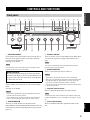
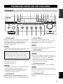
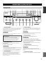
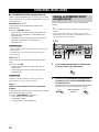
CONTROLS AND FUNCTIONS
3
INTRODUCTION
English
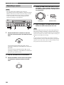
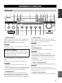
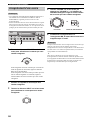
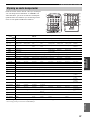
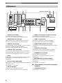
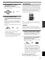
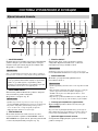
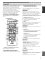
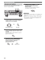
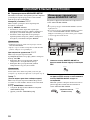
1 MASTER ON/OFF
Press inward to the ON position to turn on the power of
this unit. Press again to release it outward to the OFF
position to turn off this unit.
See page 16 for details.
Even when this unit is turned off, this unit consumes a small
amount of power to preserve the memory.
2 MAIN ZONE ON/OFF
Turns on Main Zone of this unit or sets it to the standby
mode.
See page
16
for details.
• This switch is operational only when MASTER ON/OFF is
pressed inward to the ON position.
• In the standby mode, this unit consumes a small amount of
power to receive infrared signals from the remote control.
3 SPEAKERS A/B
Turns on or off the speaker set connected to the
SPEAKERS A and/or SPEAKERS B terminals on the rear
panel each time the corresponding button is pressed (see
page 17).
4 ZONE 2 ON/OFF
Turns on Zone 2 or set it to the standby mode. When Zone
2 is turned on, signals are output at the ZONE 2 OUT
jacks.
This switch is operational only when MASTER ON/OFF is
pressed inward to the ON position.
5 ZONE CONTROL
Press to control the input source of Zone 2.
• This button is operational only when Zone 2 is turned on.
• When you press this button, the ZONE 2 indicator flashes in the
front panel display for approximately 5 seconds. Select the
input source of Zone 2 while the indicator is flashing.
• You can select the preset station when TUNER is selected as the
input source of Zone 2.
6 Remote control sensor
Receives infrared signals from the remote control.
Switch the remote control ID between ID1 and ID2 when using
multiple YAMAHA receivers or amplifiers (see pages 9, 32 and
33).
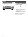
7 Front panel display
Shows information about the operational status of this
unit.
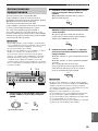
CONTROLS AND FUNCTIONS
Front panel
ON/OFF
INPUT
MAIN ZONE
PHONES
BASS
MASTER SPEAKERS
ON OFF
CD DIRECT AMPPURE DIRECT
55
1
0
1
44
22
3
3
+
–
VOLUME
l
TUNING
h
ZONE 2 ON/OFF
ZONE CONTROL
FM/AM
EDIT
A/B/C/D/E
12345678
MEMORY
MAN'L/AUTO FM
TUNING MODE
AUTO/MAN'L
BA
TREBLE
55
1
0
1
44
22
3
3
+
–
BALANCE
55
1
0
1
44
22
3
3
R
L
LOUDNESS
57
1
FLAT
6
48
210
–
30dB
3 9
REC OUT
MD/TAPE
SOURCE
CD
DVD
VCR TUNER
DTV/CBL
PHONO
0
12
12
2
8
4
∞
20
20
60
60
26
26
40
40
16
16
-dB
-dB
DISPLAY
6312 5498AB7DC0
HGFIJKLMN
E
(General model)
Note
Memory back-up
The memory back-up circuit prevents the stored data
from being lost. However, the stored data will be lost if
the power cord is disconnected from the AC wall outlet
for more than one week.
Notes
Note
Notes
Note

CONTROLS AND FUNCTIONS
4
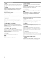
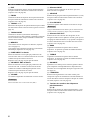
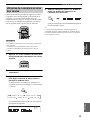
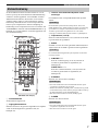
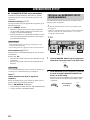
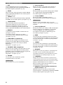
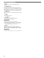
8 EDIT
Exchanges the assignment of two preset stations with each
other when TUNER is selected as the input source (see
page 28).
9 FM/AM
Switches the reception band between AM and FM when
TUNER is selected as the input source (see page 23).
0 TUNING l / h
Selects the tuning frequency when TUNER is selected as
the input source (see page 23).
A TUNING MODE
Switches the tuning mode between automatic (the AUTO
indicator turns on as a result) and manual (the AUTO
indicator turns off as a result) when TUNER is selected as
the input source.
B MEMORY
Stores a station in the system memory (see page 27).
Sets this unit to the automatic preset tuning mode (see
page 25).
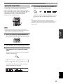
C PURE DIRECT and indicator
Allows you to listen to a source in the purest possible
sound. The indicator above it lights up when this function
is turned on.
See page 19 for details.
D CD DIRECT AMP and indicator
Allows you to listen to a CD source in the purest possible
sound. The indicator above it lights up and the front panel
display turns off when this function is turned on.
See page 19 for details.
E VOLUME
Increases or decreases the sound output level.
This does not affect the OUT (REC) level.
F INPUT selector
Selects the input source you want to listen to or watch.
G A/B/C/D/E
Selects the preset station group (A to E) when TUNER is
selected as the input source (see page 26).
H PHONES jack
Outputs audio for private listening with your headphones.
Press SPEAKERS A/B so that the SP A/B indicators turn off
before you connect your headphones to the PHONES jack.
I REC OUT selector
Selects a source for recording to the MD recorder or the
tape deck independently of the INPUT selector setting,
allowing you to record the selected source while listening
to another source (see page 20).
J BASS
Increases or decreases the low frequency response. The 0
position produces a flat response (see page 19).
K TREBLE
Increases or decreases the high frequency response. The 0
position produces a flat response (see page 19).
L BALANCE
Adjusts the sound output balance of the left and right
speakers to compensate for sound imbalances caused by
speaker locations or listening room conditions (see page
19).
M LOUDNESS
Retains a full tonal range at any volume level to
compensate for the human ears’ loss of sensitivity to high
and low-frequency ranges at a low volume level (see page
19).
N Preset station number buttons
(1 to 8)
Selects the preset station number (1 to 8) directly when
TUNER is selected as the input source (see page 28).
Note
Note

CONTROLS AND FUNCTIONS
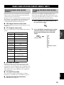
5
INTRODUCTION
English
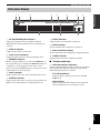
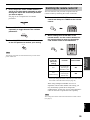
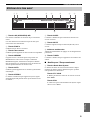
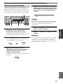
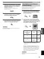
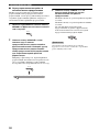
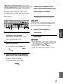
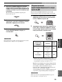
1 SP (SPEAKERS) A/B indicators
Light up according to the set of speakers selected.
Both indicators light up when both sets of speakers are
selected.
2 ZONE 2 indicator
Lights up when Zone 2 is turned on.
3 Input source indicators
Light up when this unit is in the corresponding mode.
4 MEMORY indicator
Flashes for approximately 5 seconds after MEMORY on
the front panel is pressed. While the MEMORY indicator
is flashing, store the displayed station in the system
memory by using A/B/C/D/E and one of the preset station
number buttons on the front panel.
5 AUTO indicator
Lights up when this unit is in the automatic tuning mode.
6 STEREO indicator
Lights up when this unit is receiving a strong signal for an
FM stereo broadcast while the AUTO indicator is lit.
7 SLEEP indicator
Lights up when the sleep timer is turned on.
8 MUTE indicator
Flashes while the MUTE function is turned on.
9 Multi-information display
Shows information when adjusting or changing settings.
0 TUNED indicator
Lights up when this unit is tuned into a station.
■ Europe model only
A Radio Data System indicators
The box-shaped indicator beside the name of each Radio
Data System mode lights up when the corresponding
Radio Data System mode is selected.
PTY HOLD indicator
Lights up while searching for stations in the PTY
SEEK mode.
EON indicator
Lights up when the Radio Data System station that
offers the EON data service is being received.
Front panel display
SP
DVD VCR CD TUNER PHONO
HOLDPTY
DTV/CBL
MD/TAPE
A B
ZONE2 ZONE3 MEMORY AUTO
TUNED STEREO
SLEEP
EON
PS
RT
PTY
CT
MUTE
0A9
12 4 5 6 738

CONTROLS AND FUNCTIONS
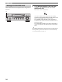
6
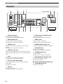
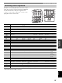
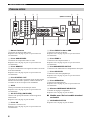
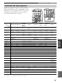
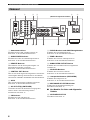
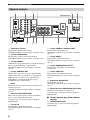
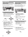
1 Antenna terminals
Connect FM and AM antennas.
See page 13 for connections information.
2 AUDIO/VIDEO jacks
Connect audio and video components.
See page 12 for connection information.
3 REMOTE jacks
These jacks are used to input/output remote control
signals.
See page 34 for connection information.
4 CONTROL OUT jack
This is a control expansion jack. Consult your nearest
authorized YAMAHA dealer or service center about this
jack.
5 AC IN
Use to plug in the supplied power cable.
See page 15 for connection information.
6 AC OUTLET(S) (SWITCHED)
Use to supply power to your other audio and video
components.
See page 15 for details.
7 CD jacks
Connect a CD player.
See page 12 for connection information.
8 PHONO jacks and GND terminal
Connect a turntable.
See page 12 for connection information.
9 ZONE 2 jacks
Connect a Zone 2 component.
See page 34 for connection information.
0 SUBWOOFER OUTPUT jack
Connect a subwoofer with built-in amplifier.
A COUPLER jacks
Connect an external unit.
See page 15 for connection information.
B SPEAKERS terminals
Connect speakers.
See page 11 for connection information.
C IMPEDANCE SELECTOR switch
Switches the impedance setting.
See page 15 for details.
■ Asia and General models only
D VOLTAGE SELECTOR
See page 15 for details.
Rear panel
AC OUTLETS
SWITCHED
IMPEDANCE SELECTOR
SET BEFORE POWER ON
SPEAKERS
A
B
AC IN
REMOTE
OUT
IN
DVD
DTV/
CBL
IN
IN
(PLAY)
OUT
(REC)
OUT
MD/
TAP E
ZONE 2
OUT
ZONE 2
OUT
MONITOR
OUT
VCR
DVD
GND
GND
AM
ANT
FM
ANT
75Ω
UNBAL.
DTV/
CBL
IN
OUT
CD
PHONO
VCR
IN
MAIN
IN
PRE
OUT
SUB
WOOFER
+12V 15mA MAX.
2
1
CONTROL OUT
COUPLER
OUTPUTAUDIOAUDIO
VIDEO
TUNER
A OR B: 4ΩMIN. /SPEAKER
A+B: 8ΩMIN. /SPEAKER
A OR B: 6ΩMIN. /SPEAKER
A+B:12ΩMIN. /SPEAKER
70 CD8AB
123 5
6
4
9
VOLTAGE
SELECTOR
(General model)

CONTROLS AND FUNCTIONS
7
INTRODUCTION
English
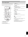
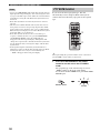
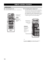
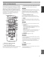
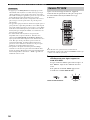
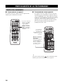
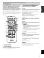
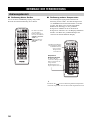
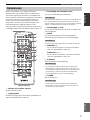
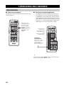
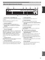
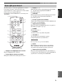
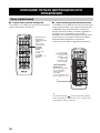
This section describes the function of each button on the
remote control used to control this unit or other
components made by YAMAHA or other manufacturers.
The functions of the buttons used to control your other
audio and video components are the same as those of the
corresponding buttons on those components. Refer to
those components’ instruction manuals for details. To
operate other components using this remote control, see
“REMOTE CONTROL FEATURES” on page 36.
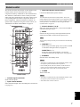
1 Infrared signal transmitter
Sends infrared signals.
2 Input selector buttons
Select the desired input source and change the control area
(see page 36).
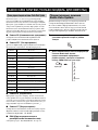
3 Radio Data System control buttons
Controls the Radio Data System features.
The Radio Data System features (FREQ/TEXT, EON, PTY
SEEK MODE and PTY SEEK START) are only applicable to the
Europe model and are operational only when TUNER is selected
as the input source. For details, see “Receiving Radio Data
System stations” on page 29.
4 Numeric buttons (1 to 8)
Select the preset station number (1 to 8) when TUNER is
selected as the input source.
5 BAND
Switches to the previously used reception band (FM or
AM) when TUNER is selected as the input source.
The frequency of the previously received station is automatically
recalled.
6 A/B/C/D/E j / i
Selects the preset station group (A to E) when TUNER
is selected as the input source (see page 28).
PRESET/CH u / d
Selects the preset station number (1 to 8) when
TUNER is selected as the input source (see page 28).
7 STANDBY
Sets this unit to the standby mode.
• This button is operational only when MASTER ON/OFF on the
front panel is pressed inward to the ON position.
• In the standby mode, this unit consumes a small amount of
power to receive infrared signals from the remote control.
• This button does not set Zone 2 to the standby mode.
8 POWER
Turns on this unit.
• This button is operational only when MASTER ON/OFF on the
front panel is pressed inward to the ON position.
• This button does not turn on Zone 2.
Remote control
STANDBY
POWER
CD
MD/TAPE
TUNER
PHONODVD
SLEEP
A
B
POWER POWER
REC
CODE SET
MUTE
MENUTITLE
VOLUME
DISC SKIP
EON
FREQ/TEXT
START
MODE PTY SEEK
BAND
A/B/C/D/E A/B/C/D/E
PRESET/CH
4321
8
10
7
09
65
ENT.
DISPLAYRETURN
TV MUTE TV INPUT
AVTV
ENTER
VCR
DTV/CBL
SPEAKERS
TV VOL
TV CH
7
8
9
0
A
B
C
D
1
2
3
4
6
5
(Europe model)
Note
Note
Notes
Notes

CONTROLS AND FUNCTIONS
8
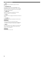
9
Changes the control area (see page 36).
0 SPEAKERS A/B
Turns on or off the set of speakers connected to the
SPEAKERS A and/or SPEAKERS B terminals on the rear
panel of this unit when the corresponding button is
pressed each time.
A CODE SET
Use to set up remote control codes (see page 38).
B SLEEP
Sets the sleep timer.
C VOLUME +/–
Increases or decreases the sound output level.
• This does not affect the OUT (REC) level.
• When you press VOLUME +/– to control the sound output
level of this unit, VOLUME on the front panel rotates.
D MUTE
Mutes the sound output. Press again to restore the sound
output to the previous volume level (see page 22).
The sound output to Zone 2 is not muted.
Notes
Note

CONTROLS AND FUNCTIONS
9
INTRODUCTION
English
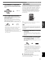
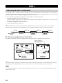
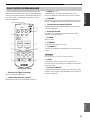
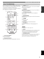
This section describes the function of each button on the
Zone 2 remote control used to control Zone 2. You can
also use the Zone 2 remote control to control YAMAHA
CD players and YAMAHA cassette tape deck.
1 Infrared signal transmitter
Sends infrared signals.
2 Input selector buttons
Select the desired input source of Zone 2.
3 PRESET u / d
Selects the preset station number (1 to 8) when TUNER is
selected as the input source.
4 A/B/C/D/E
Selects the preset station group (A to E) when TUNER is
selected as the input source.
5 CD/TAPE control buttons
Controls YAMAHA CD players or YAMAHA cassette
tape deck.
6 ID1/ID2 switch
Switches the remote control ID between ID1 and ID2 (see
page 33).
7 POWER
Turns on Zone 2.
8 STANDBY
Sets Zone 2 to the standby mode.
9 VOLUME +/–
Increases or decreases the sound output level of Zone 2.
This does not affect the OUT (REC) level.
0 MUTE
Mutes the sound output to Zone 2. Press again to restore
the sound output to the previous volume level.
A CD/TAPE switch
Switches the function of the control buttons numbered 5
between controlling YAMAHA CD players and
controlling YAMAHA cassette tape deck.
Zone 2 remote control
CD PHONO
ZONE 2
TUNER
MD/TAPE VCR DTV/CBL
DVD
POWER
STANDBY
+
–
u
d
REC
DISC
p
DIR BDIR A
A/B
A/B/C/D/E
MUTE
PRESET
VOLUME
TAPECDID2ID1
w
e
f
b
s
a
DISPLAY
7
8
9
0
A
1
2
3
4
5
6
(Europe model)
Note

CONTROLS AND FUNCTIONS
10
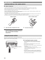
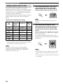
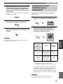
■ Notes on batteries
• Change all of the batteries if the operation range of the remote controls decreases.
• Use AA, R6, UM-3 batteries for the remote control and AAA, R03, UM-4 batteries for the Zone 2 remote control.
• Make sure that the polarities are correct. See the illustration inside the battery compartment of each remote control.
• Remove the batteries if the remote controls are not used for an extended period of time.
• Do not use old batteries together with new ones.
• Do not use different types of batteries (such as alkaline and manganese batteries) together. Read the packaging carefully as these
different types of batteries may have the same shape and color.
• We strongly recommend using alkaline batteries.
• If the batteries have leaked, dispose of them immediately. Avoid touching the leaked material or letting it come into contact with
clothing, etc. Clean the battery compartment thoroughly before installing new batteries.
• Do not throw away batteries with general house waste; dispose of them correctly in accordance with your local regulations.
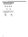
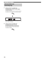
Remote control Zone 2 remote control
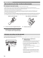
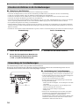
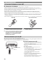
1 Open the battery compartment cover.
2 Insert the supplied batteries in each remote
control according to the polarity markings (+
and –) on the inside of the battery
compartment.
3 Close the cover back.
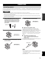
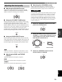
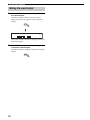
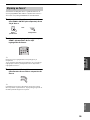
The remote controls transmit a directional infrared beam.
Be sure to aim the remote controls directly at the remote control sensor on the front panel of this unit or on the infrared
signal receiver in Zone 2 during operation.
■ Handling the remote controls
• The area between the remote controls and this unit (or the
infrared signal receiver in Zone 2) must be clear of large
obstacles.
• Do not spill water or other liquids on the remote controls.
• Do not drop the remote controls.
• Do not leave or store the remote controls in the following types
of conditions:
– places of high humidity, such as near a bath
– places of high temperature, such as near a heater or a stove
– places of extremely low temperatures
– dusty places
• Do not expose the remote control sensor to strong lighting, in
particular, an inverter type fluorescent lamp; otherwise, the
remote controls may not work properly. If necessary, position
this unit away from direct lighting.
Installing batteries in the remote controls
1
3
2
1
3
2
Using the remote controls
VOLUME
ON/OFF
INPUT
MAIN ZONE
PHONES
BASS
MASTER SPEAKERS
ON OFF
CD DIRECT AMPPURE DIRECT
55
1
0
1
44
22
3
3
+
–
l
TUNING
h
ZONE 2 ON/OFF
ZONE CONTROL
FM/AM
EDIT
A/B/C/D/E
12345678
MEMORY
MAN'L/AUTO FM
TUNING MODE
AUTO/MAN'L
BA
TREBLE
55
1
0
1
44
22
3
3
+
–
BALANCE
55
1
0
1
44
22
3
3
R
L
LOUDNESS
57
1
FLAT
6
48
210
–
30dB
3
9
REC OUT
MD/TAPE
SOURCE
CD
DVD
VCR TUNER
DTV/CBL
PHONO
30 30
STANDBY
POWER
CD
MD/TAPE
TUNER
PHONODVD
SLEEP
A
B
POWER POWER
REC
CODE SET
MUTE
MENUTITLE
VOLUME
DISC SKIP
EON
FREQ/TEXT
START
MODE PTY SEEK
BAND
A/B/C/D/E A/B/C/D/E
PRESET/CH
4321
8
10
7
09
65
ENT.
DISPLAYRETURN
TV MUTE TV INPUT
AVTV
ENTER
VCR
DTV/CBL
SPEAKERS
TV VOL
TV CH
Approximately 6 m (19.7 ft)

CONNECTIONS
11
PREPARATION
English
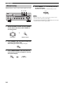
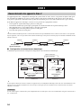
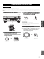
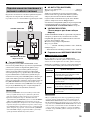
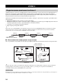
Be sure to connect the left channel (L), right channel (R), “+” (red) and “–” (black) properly. If the connections are faulty,
no sound will be heard from the speakers, and if the polarity of the speaker connections is incorrect, the sound will be
unnatural and lack bass.
• Before connecting the speakers, make sure that the power of this unit is turned off.
• Do not let the bare speaker wires touch each other or do not let them touch any metal part of this unit. This could
damage this unit and/or the speakers.
• Use magnetically shielded speakers. If this type of speakers still creates the interference with the monitor, place the
speakers away from the monitor.
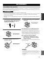
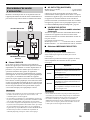
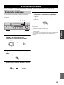
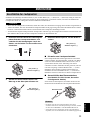
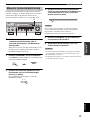
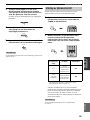
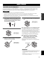
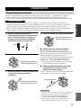
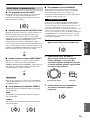
1 Remove approximately 10 mm (3/8 in) of
insulation from the end of each speaker
cable and twist the exposed wires of the
cable together to eliminate the risk of a
short-circuit.
2 Unscrew the knob.
3 Insert one bare wire into the hole in the side
of each terminal.
4 Tighten the knob to secure the wire.
■ Notes on the speaker cord
A speaker cord is actually a pair of insulated cables
running side by side. One cable is colored or shaped
differently, perhaps with a stripe, groove or ridge. Connect
the striped, grooved or ridged cable to the “+” (red)
terminals on this unit and your speaker. Connect the plain
cable to the “–” (black) terminals on this unit and your
speaker.
■ Connecting the banana plug
(U.S.A., Canada, Australia and General
models only)
First, tighten the knob and then insert the banana plug into
the end of the corresponding terminal.
• One or two speaker sets can be connected to this unit. If you use
only one speaker set, connect it to either the SPEAKERS A or
SPEAKERS B terminals.
• Use speakers with the specified impedance shown on the rear
panel of this unit.
CONNECTIONS
Connecting speakers
CAUTION
10 mm (3/8 in)
Red: positive (+)
Black: negative (–)
Red: positive (+)
Black: negative (–)
Notes
Red: positive (+)
Black: negative (–)
Banana plug

12
CONNECTIONS
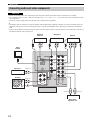
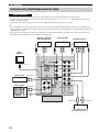
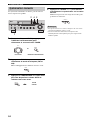
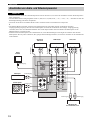
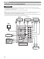
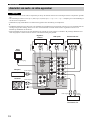
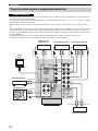
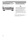
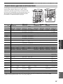
• Do not connect this unit or other components to the main power until all connections between components are complete.
• All connections must be correct: L (left) to L, R (right) to R, “+” to “+” and “–” to “–”. Also, refer to the owner’s manual for each of
your components.
• Use the RCA type pin plug cables for audio and video components except speakers.
y
• The PHONO jacks are designed to connect a turntable with an MM or high-output MC cartridge. If you have a turntable with a low-
output MC cartridge, use an in-line boosting transformer or an MC-head amplifier when connecting your turntable to the PHONO
jacks.
• Connect your turntable to the GND terminal to reduce noise in the signal. However, you may hear less noise without the connection to
the GND terminal for some record players.
Connecting audio and video components
CAUTION
DVD
DTV/
CBL
IN
IN
(PLAY)
OUT
(REC)
OUT
MD/
TAPE
ZONE 2
OUT
VCR
GND
GND
AM
ANT
FM
ANT
75Ω
UNBAL.
CD
PHONO
AUDIOAUDIO
VIDEO
TUNER
R
L
LR LR
L
R
L
R
L
R
LRLR
V
V V
V
V
MONITOR
OUT
DVD
DTV/
CBL
IN
OUT
VCR
ZONE 2
OUT
Turntable
DVD player
Audio in
VCR, etc.
CD player
MD recorder,
Tape deck, etc.
Audio out
Audio out
GND
Audio out
Audio out
Audio in Audio out
Digital TV,
Cable TV
Video out
Video out
Audio out
Video out
Video in
Video
monitor
Video in

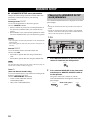
13
CONNECTIONS
PREPARATION
English
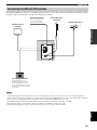
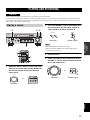
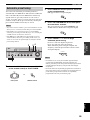
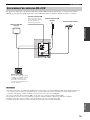
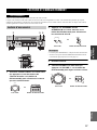
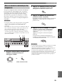
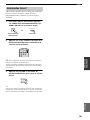
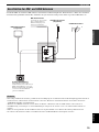
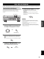
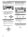
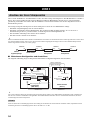
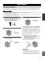
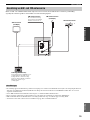
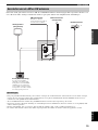
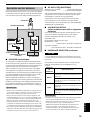
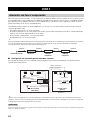
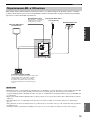
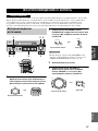
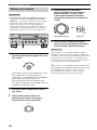
Both AM and FM indoor antennas are included with this unit. In general, these antennas should provide sufficient signal
strength. Connect each antenna correctly to the designated terminals.
• A properly installed outdoor antenna provides clearer reception than an indoor one. If you experience poor reception quality, an
outdoor antenna may improve the quality. Consult your nearest authorized YAMAHA dealer or service center about outdoor antennas.
• If you connect an outdoor FM antenna to this unit, do not connect the indoor FM antenna to this unit.
• To minimize interference from automobile ignition, locate the antenna as far from heavy traffic as possible.
• Keep the feeder cable or coaxial cable as short as possible. Do not bundle or roll up excess cable.
• The antenna should be placed at least 2 meters from reinforced concrete walls or metal structures.
Connecting the AM and FM antennas
Notes
GND
GND
AM
ANT
FM
ANT
75Ω
UNBAL.
CD
TUNER
AM loop antenna
(included)
Indoor FM antenna
(included)
Outdoor AM antenna
Use a 5 to 10 m of vinyl-
covered wire extended
outdoors from a window.
Outdoor FM antenna
Ground (GND terminal)
For maximum safety and
minimum interference, connect
the antenna GND terminal to a
good earth ground. A good earth
ground is a metal stake driven into
moist earth.

14
CONNECTIONS
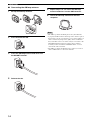
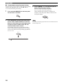
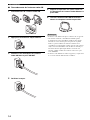
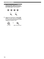
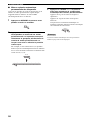
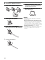
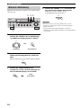
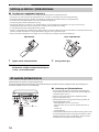
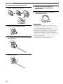
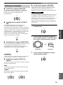
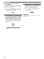
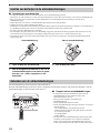
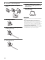
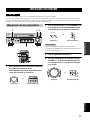
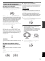
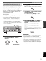
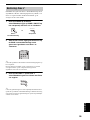
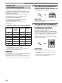
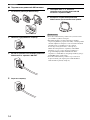
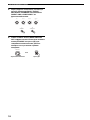
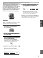
■ Connecting the AM loop antenna
1 Set up the AM loop antenna.
2 Press and hold the tab.
3 Insert the AM loop antenna lead wires into
the AM ANT terminal.
4 Release the tab.
5 Repeat steps 2 to 4 to insert the AM loop
antenna lead wires into the GND terminal.
6 Orient the AM loop antenna for the best
reception.
• The AM loop antenna should be placed away from this unit.
• A properly installed outdoor antenna provides clearer reception
than an indoor one. If you experience poor reception quality, an
outdoor antenna may improve the quality. It is recommended
that you should connect a 5 to 10 m of vinyl-covered wire to the
AM ANT terminal and extend it outdoors from a window.
Consult your nearest authorized YAMAHA dealer or service
center about outdoor antennas.
• The AM loop antenna should always be connected, even if an
outdoor AM antenna is connected to this unit.
Notes

15
CONNECTIONS
PREPARATION
English
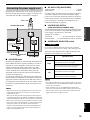
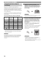
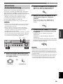
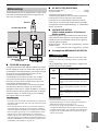
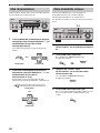
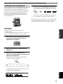
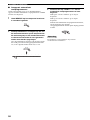
Plug the power cable into the AC IN on the rear panel of
this unit and then plug the power supply cord into the AC
wall outlet after all other connections are complete.
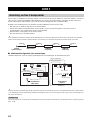
■ COUPLER jacks
Removing the jumper pins from the PRE OUT/MAIN IN
jacks enables this unit to operate separately as a control
amplifier or a power amplifier. These jacks are used to
connect a signal-processing system such as a graphic
equalizer or a surround-sound processor to this unit. If
such an external unit is connected to these jacks, the
VOLUME control of this unit can be used to adjust the
overall sound output level.
To connect an external unit, first remove the jumper pins
from the PRE OUT/MAIN IN jacks and then connect the
input jacks of that external unit to the PRE OUT jacks or
its output jacks to the MAIN IN jacks. For details, refer to
the owner’s manual included with the external unit to be
connected.
• When you do not use the COUPLER jacks, never remove the
jumper pins from these jacks. If removed, no sound will be
output from this unit.
• When you use this unit with an external unit connected to the
COUPLER jacks, make sure that the CD DIRECT AMP button
and the PURE DIRECT button on the front panel are turned off.
• When you use this unit as a power amplifier, connect the output
jacks of an external control amplifier, etc. to the MAIN IN jacks
of this unit. In this case, the controls of this unit will not
function except the PHONES jack and the SPEAKERS A/B
buttons. Use the controls on the external control amplifier to
make volume adjustments, etc.
■ AC OUTLET(S) (SWITCHED)
Australia model ......................................................1 outlet
Other models ....................................................... 2 outlets
Use these outlets to connect the power supply cords from
your other components to this unit. The outlets supply
power to any connected components whenever the power
of this unit is turned on. For information on the maximum
power (total power consumption of components), see
“SPECIFICATIONS” on page 42.
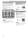
■ VOLTAGE SELECTOR
(Asia and General models only)
VOLTAGE SELECTOR on the rear panel of this unit must
be set for your local main voltage BEFORE plugging the
power supply cord into the AC wall outlet.
Voltages are as follows:
Asia model ......................... AC 220/230–240 V, 50/60 Hz
General model...... AC 110/120/220/230–240 V, 50/60 Hz
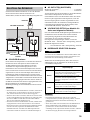
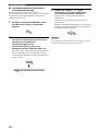
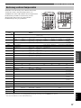
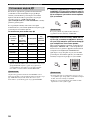
■ IMPEDANCE SELECTOR switch
Do not slide the IMPEDANCE SELECTOR switch while the
power of this unit is turned on, as doing so may damage the unit.
Select the switch position (left or right) according to the
impedance of the speakers in your system.
• The Canada model cannot use two separate speaker sets (A and
B) simultaneously when the IMPEDANCE SELECTOR switch
is slid to the 6
Ω position.
• If this unit fails to turn on, the IMPEDANCE SELECTOR
switch may not be fully slid to either position. If this is the case,
slide the switch all the way to either position when the power
supply to this unit is completely cut off.
Connecting the power supply cord
Notes
AC OUTLETS
SWITCHED
IMPEDANCE SELECTOR
SET BEFORE POWER ON
AC IN
A OR B: 4ΩMIN. /SPEAKER
A+B: 8ΩMIN. /SPEAKER
A OR B: 6ΩMIN. /SPEAKER
A+B:12ΩMIN. /SPEAKER
VOLTAGE
SELECTOR
(General model)
IMPEDANCE SELECTOR
switch
Power cable
VOLTAGE SELECTOR
AC OUTLET(S)
Switch
position
Impedance level
Right
If you use one set (A or B), the impedance of
each speaker must be 6
Ω or higher.
If you use two sets (A and B), the impedance
of each speaker must be 12
Ω or higher.
Left
If you use one set (A or B), the impedance of
each speaker must be 4
Ω or higher.
If you use two sets (A and B), the impedance
of each speaker must be 8
Ω or higher.
Notes
CAUTION

16
CONNECTIONS
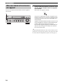
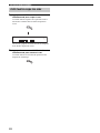
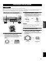
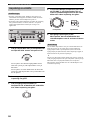
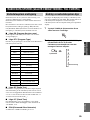
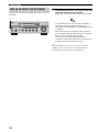
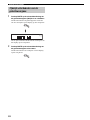
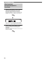
When all connections are complete, turn on the power of
this unit.
1 Press MASTER ON/OFF on the front panel
inward to the ON position to turn on the
power of this unit.
Main Zone of this unit turns on.
You can set Main Zone of this unit to the standby
mode by pressing MAIN ZONE ON/OFF on the front
panel or STANDBY on the remote control.
Press MAIN ZONE ON/OFF on the front panel or
POWER on the remote control to turn Main Zone of
this unit on again.
Press MASTER ON/OFF on the front panel again to
release it outward to the OFF position to turn off this
unit.
y
While MASTER ON/OFF on the front panel is pressed inward to
the ON position, you can turn on Zone 2 or set it to the standby
mode independently (see page 35).
Turning on and off this unit
ON/OFF
INPUT
MAIN ZONE
PHONES
BASS
MASTER SPEAKERS
ON OFF
CD DIRECT AMPPURE DIRECT
55
1
0
1
44
22
3
3
+
–
VOLUME
l
TUNING
h
ZONE 2 ON/OFF
ZONE CONTROL
FM/AM
EDIT
A/B/C/D/E
12345678
MEMORY
MAN'L/AUTO FM
TUNING MODE
AUTO/MAN'L
BA
TREBLE
55
1
0
1
44
22
3
3
+
–
BALANCE
55
1
0
1
44
22
3
3
R
L
LOUDNESS
57
1
FLAT
6
48
210
–
30dB
3
9
REC OUT
MD/TAPE
SOURCE
CD
DVD
VCR TUNER
DTV/CBL
PHONO
1
0
12
12
2
8
4
∞
20
20
60
60
26
26
40
40
16
16
-dB
-dB
MASTER
ON OFF

PLAYING AND RECORDING
17
BASIC
OPERATION
English
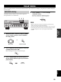
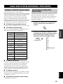
Extreme caution should be exercised when you play back CDs encoded in DTS.
If you play back a CD encoded in DTS on a DTS-incompatible CD player, you will only hear some unwanted noise that may damage
your speakers. Check whether your CD player supports CDs encoded in DTS. Also, check the sound output level of your CD player
before you play back a CD encoded in DTS.
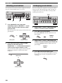
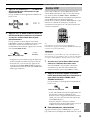
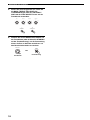
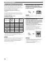
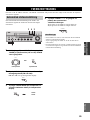
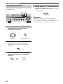
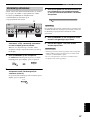
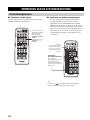
1 Rotate the INPUT selector on the front panel
(or press one of the input selector buttons on
the remote control) to select the desired
input source.
2 Press SPEAKERS A and/or SPEAKERS B on
the front panel or on the remote control to
select speakers A and/or speakers B.
• Both SPEAKERS A and B can be selected.
• Make sure that the IMPEDANCE SELECTOR switch is
correctly set (see page 15).
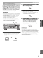
3 Play the source.
4 Rotate VOLUME on the front panel (or press
VOLUME +/– on the remote control) to adjust
the sound output level.
PLAYING AND RECORDING
CAUTION
Playing a source
ON/OFF
INPUT
MAIN ZONE
PHONES
BASS
MASTER SPEAKERS
ON OFF
CD DIRECT AMPPURE DIRECT
55
1
0
1
44
22
3
3
+
–
VOLUME
l
TUNING
h
ZONE 2 ON/OFF
ZONE CONTROL
FM/AM
EDIT
A/B/C/D/E
12345678
MEMORY
MAN'L/AUTO FM
TUNING MODE
AUTO/MAN'L
BA
TREBLE
55
1
0
1
44
22
3
3
+
–
BALANCE
55
1
0
1
44
22
3
3
R
L
LOUDNESS
57
1
FLAT
6
48
210
–
30dB
3
9
REC OUT
MD/TAPE
SOURCE
CD
DVD
VCR TUNER
DTV/CBL
PHONO
1
6
5
4
2 5
5
0
12
12
2
8
4
∞
20
20
60
60
26
26
40
40
16
16
-dB
-dB
STANDBY
POWER
CD
MD/TAPE
TUNER
PHONODVD
SLEEP
A
B
POWER POWER
REC
CODE SET
VOLUME
DISC SKIP
EON
FREQ/TEXT
START
MODE PTY SEEK
AVTV
VCR
DTV/CBL
SPEAKERS
TV VOL
TV CH
2
4
1
6
INPUT
STANDBY
POWER
CD
MD/TAPE
TUNER
PHONODVD
POWER POWER
AVTV
VCR
DTV/CBL
Front panel Remote control
or
Notes
SPEAKERS
BA
A
B
SPEAKERS
or
Front panel
Remote control
0
12
12
2
8
4
∞
20
20
60
60
26
26
40
40
16
16
-dB
-dB
VOLUME
VOLUME
Remote control
Front panel
or

18
PLAYING AND RECORDING
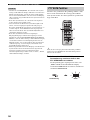
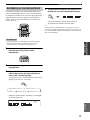
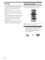
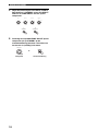
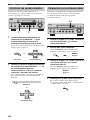
5 Adjust the tonal quality by using the BASS,
TREBLE, BALANCE and LOUDNESS controls
or the CD DIRECT AMP and the PURE
DIRECT buttons on the front panel.
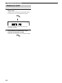
6 Press MAIN ZONE ON/OFF on the front panel
again (or press STANDBY on the remote
control) to finish using this unit and set it to
the standby mode.
BASS
55
1
0
1
44
22
3
3
+
–
TREBLE
55
1
0
1
44
22
3
3
+
–
BALANCE
55
1
0
1
44
22
3
3
R
L
LOUDNESS
57
1
FLAT
6
48
210
–
30dB
3
9
PURE DIRECT
CD DIRECT AMP
ON/OFF
MAIN ZONE
STANDBY
Remote control
Front panel
or
Pagina se încarcă...
Pagina se încarcă...
Pagina se încarcă...
Pagina se încarcă...
Pagina se încarcă...
Pagina se încarcă...
Pagina se încarcă...
Pagina se încarcă...
Pagina se încarcă...
Pagina se încarcă...
Pagina se încarcă...
Pagina se încarcă...
Pagina se încarcă...
Pagina se încarcă...
Pagina se încarcă...
Pagina se încarcă...
Pagina se încarcă...
Pagina se încarcă...
Pagina se încarcă...
Pagina se încarcă...
Pagina se încarcă...
Pagina se încarcă...
Pagina se încarcă...
Pagina se încarcă...
Pagina se încarcă...
Pagina se încarcă...
Pagina se încarcă...
Pagina se încarcă...
Pagina se încarcă...
Pagina se încarcă...
Pagina se încarcă...
Pagina se încarcă...
Pagina se încarcă...
Pagina se încarcă...
Pagina se încarcă...
Pagina se încarcă...
Pagina se încarcă...
Pagina se încarcă...
Pagina se încarcă...
Pagina se încarcă...
Pagina se încarcă...
Pagina se încarcă...
Pagina se încarcă...
Pagina se încarcă...
Pagina se încarcă...
Pagina se încarcă...
Pagina se încarcă...
Pagina se încarcă...
Pagina se încarcă...
Pagina se încarcă...
Pagina se încarcă...
Pagina se încarcă...
Pagina se încarcă...
Pagina se încarcă...
Pagina se încarcă...
Pagina se încarcă...
Pagina se încarcă...
Pagina se încarcă...
Pagina se încarcă...
Pagina se încarcă...
Pagina se încarcă...
Pagina se încarcă...
Pagina se încarcă...
Pagina se încarcă...
Pagina se încarcă...
Pagina se încarcă...
Pagina se încarcă...
Pagina se încarcă...
Pagina se încarcă...
Pagina se încarcă...
Pagina se încarcă...
Pagina se încarcă...
Pagina se încarcă...
Pagina se încarcă...
Pagina se încarcă...
Pagina se încarcă...
Pagina se încarcă...
Pagina se încarcă...
Pagina se încarcă...
Pagina se încarcă...
Pagina se încarcă...
Pagina se încarcă...
Pagina se încarcă...
Pagina se încarcă...
Pagina se încarcă...
Pagina se încarcă...
Pagina se încarcă...
Pagina se încarcă...
Pagina se încarcă...
Pagina se încarcă...
Pagina se încarcă...
Pagina se încarcă...
Pagina se încarcă...
Pagina se încarcă...
Pagina se încarcă...
Pagina se încarcă...
Pagina se încarcă...
Pagina se încarcă...
Pagina se încarcă...
Pagina se încarcă...
Pagina se încarcă...
Pagina se încarcă...
Pagina se încarcă...
Pagina se încarcă...
Pagina se încarcă...
Pagina se încarcă...
Pagina se încarcă...
Pagina se încarcă...
Pagina se încarcă...
Pagina se încarcă...
Pagina se încarcă...
Pagina se încarcă...
Pagina se încarcă...
Pagina se încarcă...
Pagina se încarcă...
Pagina se încarcă...
Pagina se încarcă...
Pagina se încarcă...
Pagina se încarcă...
Pagina se încarcă...
Pagina se încarcă...
Pagina se încarcă...
Pagina se încarcă...
Pagina se încarcă...
Pagina se încarcă...
Pagina se încarcă...
Pagina se încarcă...
Pagina se încarcă...
Pagina se încarcă...
Pagina se încarcă...
Pagina se încarcă...
Pagina se încarcă...
Pagina se încarcă...
Pagina se încarcă...
Pagina se încarcă...
Pagina se încarcă...
Pagina se încarcă...
Pagina se încarcă...
Pagina se încarcă...
Pagina se încarcă...
Pagina se încarcă...
Pagina se încarcă...
Pagina se încarcă...
Pagina se încarcă...
Pagina se încarcă...
Pagina se încarcă...
Pagina se încarcă...
Pagina se încarcă...
Pagina se încarcă...
Pagina se încarcă...
Pagina se încarcă...
Pagina se încarcă...
Pagina se încarcă...
Pagina se încarcă...
Pagina se încarcă...
Pagina se încarcă...
Pagina se încarcă...
Pagina se încarcă...
Pagina se încarcă...
Pagina se încarcă...
Pagina se încarcă...
Pagina se încarcă...
Pagina se încarcă...
Pagina se încarcă...
Pagina se încarcă...
Pagina se încarcă...
Pagina se încarcă...
Pagina se încarcă...
Pagina se încarcă...
Pagina se încarcă...
Pagina se încarcă...
Pagina se încarcă...
Pagina se încarcă...
Pagina se încarcă...
Pagina se încarcă...
Pagina se încarcă...
Pagina se încarcă...
Pagina se încarcă...
Pagina se încarcă...
Pagina se încarcă...
Pagina se încarcă...
Pagina se încarcă...
Pagina se încarcă...
Pagina se încarcă...
Pagina se încarcă...
Pagina se încarcă...
Pagina se încarcă...
Pagina se încarcă...
Pagina se încarcă...
Pagina se încarcă...
Pagina se încarcă...
Pagina se încarcă...
Pagina se încarcă...
Pagina se încarcă...
Pagina se încarcă...
Pagina se încarcă...
Pagina se încarcă...
Pagina se încarcă...
Pagina se încarcă...
Pagina se încarcă...
Pagina se încarcă...
Pagina se încarcă...
Pagina se încarcă...
Pagina se încarcă...
Pagina se încarcă...
Pagina se încarcă...
Pagina se încarcă...
Pagina se încarcă...
Pagina se încarcă...
Pagina se încarcă...
Pagina se încarcă...
Pagina se încarcă...
Pagina se încarcă...
Pagina se încarcă...
Pagina se încarcă...
Pagina se încarcă...
Pagina se încarcă...
Pagina se încarcă...
Pagina se încarcă...
Pagina se încarcă...
Pagina se încarcă...
Pagina se încarcă...
Pagina se încarcă...
Pagina se încarcă...
Pagina se încarcă...
Pagina se încarcă...
Pagina se încarcă...
Pagina se încarcă...
Pagina se încarcă...
Pagina se încarcă...
Pagina se încarcă...
Pagina se încarcă...
Pagina se încarcă...
Pagina se încarcă...
Pagina se încarcă...
Pagina se încarcă...
Pagina se încarcă...
Pagina se încarcă...
Pagina se încarcă...
Pagina se încarcă...
Pagina se încarcă...
Pagina se încarcă...
Pagina se încarcă...
Pagina se încarcă...
Pagina se încarcă...
Pagina se încarcă...
-
 1
1
-
 2
2
-
 3
3
-
 4
4
-
 5
5
-
 6
6
-
 7
7
-
 8
8
-
 9
9
-
 10
10
-
 11
11
-
 12
12
-
 13
13
-
 14
14
-
 15
15
-
 16
16
-
 17
17
-
 18
18
-
 19
19
-
 20
20
-
 21
21
-
 22
22
-
 23
23
-
 24
24
-
 25
25
-
 26
26
-
 27
27
-
 28
28
-
 29
29
-
 30
30
-
 31
31
-
 32
32
-
 33
33
-
 34
34
-
 35
35
-
 36
36
-
 37
37
-
 38
38
-
 39
39
-
 40
40
-
 41
41
-
 42
42
-
 43
43
-
 44
44
-
 45
45
-
 46
46
-
 47
47
-
 48
48
-
 49
49
-
 50
50
-
 51
51
-
 52
52
-
 53
53
-
 54
54
-
 55
55
-
 56
56
-
 57
57
-
 58
58
-
 59
59
-
 60
60
-
 61
61
-
 62
62
-
 63
63
-
 64
64
-
 65
65
-
 66
66
-
 67
67
-
 68
68
-
 69
69
-
 70
70
-
 71
71
-
 72
72
-
 73
73
-
 74
74
-
 75
75
-
 76
76
-
 77
77
-
 78
78
-
 79
79
-
 80
80
-
 81
81
-
 82
82
-
 83
83
-
 84
84
-
 85
85
-
 86
86
-
 87
87
-
 88
88
-
 89
89
-
 90
90
-
 91
91
-
 92
92
-
 93
93
-
 94
94
-
 95
95
-
 96
96
-
 97
97
-
 98
98
-
 99
99
-
 100
100
-
 101
101
-
 102
102
-
 103
103
-
 104
104
-
 105
105
-
 106
106
-
 107
107
-
 108
108
-
 109
109
-
 110
110
-
 111
111
-
 112
112
-
 113
113
-
 114
114
-
 115
115
-
 116
116
-
 117
117
-
 118
118
-
 119
119
-
 120
120
-
 121
121
-
 122
122
-
 123
123
-
 124
124
-
 125
125
-
 126
126
-
 127
127
-
 128
128
-
 129
129
-
 130
130
-
 131
131
-
 132
132
-
 133
133
-
 134
134
-
 135
135
-
 136
136
-
 137
137
-
 138
138
-
 139
139
-
 140
140
-
 141
141
-
 142
142
-
 143
143
-
 144
144
-
 145
145
-
 146
146
-
 147
147
-
 148
148
-
 149
149
-
 150
150
-
 151
151
-
 152
152
-
 153
153
-
 154
154
-
 155
155
-
 156
156
-
 157
157
-
 158
158
-
 159
159
-
 160
160
-
 161
161
-
 162
162
-
 163
163
-
 164
164
-
 165
165
-
 166
166
-
 167
167
-
 168
168
-
 169
169
-
 170
170
-
 171
171
-
 172
172
-
 173
173
-
 174
174
-
 175
175
-
 176
176
-
 177
177
-
 178
178
-
 179
179
-
 180
180
-
 181
181
-
 182
182
-
 183
183
-
 184
184
-
 185
185
-
 186
186
-
 187
187
-
 188
188
-
 189
189
-
 190
190
-
 191
191
-
 192
192
-
 193
193
-
 194
194
-
 195
195
-
 196
196
-
 197
197
-
 198
198
-
 199
199
-
 200
200
-
 201
201
-
 202
202
-
 203
203
-
 204
204
-
 205
205
-
 206
206
-
 207
207
-
 208
208
-
 209
209
-
 210
210
-
 211
211
-
 212
212
-
 213
213
-
 214
214
-
 215
215
-
 216
216
-
 217
217
-
 218
218
-
 219
219
-
 220
220
-
 221
221
-
 222
222
-
 223
223
-
 224
224
-
 225
225
-
 226
226
-
 227
227
-
 228
228
-
 229
229
-
 230
230
-
 231
231
-
 232
232
-
 233
233
-
 234
234
-
 235
235
-
 236
236
-
 237
237
-
 238
238
-
 239
239
-
 240
240
-
 241
241
-
 242
242
-
 243
243
-
 244
244
-
 245
245
-
 246
246
-
 247
247
-
 248
248
-
 249
249
-
 250
250
-
 251
251
-
 252
252
-
 253
253
-
 254
254
-
 255
255
-
 256
256
-
 257
257
-
 258
258
-
 259
259
-
 260
260
-
 261
261
-
 262
262
-
 263
263
-
 264
264
-
 265
265
-
 266
266


Yamaha RX-797 Manualul proprietarului
- Categorie
- CD playere
- Tip
- Manualul proprietarului
în alte limbi
- Türkçe: Yamaha RX-797 El kitabı
- français: Yamaha RX-797 Le manuel du propriétaire
- русский: Yamaha RX-797 Инструкция по применению
- English: Yamaha RX-797 Owner's manual
- suomi: Yamaha RX-797 Omistajan opas
- Deutsch: Yamaha RX-797 Bedienungsanleitung
- svenska: Yamaha RX-797 Bruksanvisning
- dansk: Yamaha RX-797 Brugervejledning
- Nederlands: Yamaha RX-797 de handleiding