Plymovent Limestone feeder Manual de utilizare
- Tip
- Manual de utilizare

www.plymovent.com
EN Installation and user manual
NL Installatie- en gebruikershandleiding
DE Installations- und Betriebsanleitung
FR Manuel d’installation et d’utilisation
ES Manual de instalación y de manejo
SE Installations- och användarmanual
RO Manualul utilizatorului
RO Alimentatorpiatrădevar
SE Kalkstenmatar
ES Alimentadordepiedracaliza
FR Dispositifd’alimentationencalcaire
DE Precoatieranlage
NL Kalksteendoseerinstallatie
EN Limestonefeeder
OILSHIELD

0507061600/010713/DOilShield 1
EN – OrigiNal iNstructiON
All rights reserved. The information given in this document has been collected for the general convenience of our clients. It has been based on general data pertaining to construction material
properties and working methods known to us at the time of issue of the document and is therefore subject at any time to change or amendment and the right to change or amend is hereby expressly
reserved. The instructions in this publication only serve as a guideline for installation, use, maintenance and repair of the product mentioned on the cover page of this document. This publication is to
be used for the standard model of the product of the type given on the cover page. Thus the manufacturer cannot be held responsible for any damage resulting from the application of this publication
to the version actually delivered to you. This publication has been written with great care. However, the manufacturer cannot be held responsible, either for any errors occurring in this publication or
for their consequences.
Nl – VErtaliNg VaN DE OOrsprONkElijkE gEbruiksaaNwijziNg
Alle rechten voorbehouden. De in deze handleiding verstrekte informatie is gebaseerd op algemene gegevens aangaande de ons ten tijde van verschijnen bekende constructies, materiaaleigenschappen
en werkmethoden, zodat wijzingen worden voorbehouden. Om deze reden dienen de gegeven instructies slechts als richtlijn voor het installeren, gebruiken, onderhouden en repareren van het op de
voorzijde van dit document vermelde product. Deze handleiding is geldig voor het product in de standaard uitvoering. De fabrikant kan derhalve niet aansprakelijk worden gesteld voor eventuele schade
voortvloeiend uit de van de standaard uitvoering afwijkende specicaties van het aan u geleverde product. Deze handleiding is met alle mogelijke zorg samengesteld, maar de fabrikant kan geen
verantwoording op zich nemen voor eventuele fouten in deze handleiding of voor de gevolgen daarvan.
DE – ÜbErsEtzuNg DEr OrigiNalbEtriEbsaNlEituNg
Alle Rechte vorbehalten. Die in dieser Anleitung enthaltenen Informationen basieren auf allgemeinen Daten bezüglich der Konstruktion, der Materialeigenschaften und der Arbeitsmethoden, die uns zur
Zeit der Veröffentlichung bekannt waren; Änderungen werden somit vorbehalten. Aus diesem Grunde dienen die gegebenen Vorschriften nur als Leitfaden für das Installieren, Benutzen, Warten und
Reparieren des auf der Vorderseite dieser Anleitung angegebenen Produktes. Diese Ausgabe gilt für die Standardausführung des Produktes. Der Hersteller haftet daher nicht für eventuelle Schäden,
die sich aus der Anwendung dieser Ausgabe auf Ihr von der Standardausführung abweichendes Produkt ergeben. Diese Ausgabe wurde mit größter Sorgfalt zusammengestellt. Der Hersteller haftet
jedoch nicht für eventuelle Fehler in dieser Ausgabe oder für daraus resultierende Folgen.
Fr – traDuctiON DE la NOticE OrigiNalE
Tous droits réservés. Le présent manuel a été mis au point à partir de données relatives à la construction, aux caractéristiques des matériaux et aux méthodes de production dont nous étions au
courant à la parution du manuel. Le manuel est donc sujet à modication à tout moment et nous nous réservons explicitement le droit à une telle modication. Pour la même raison, ce manuel servira
simplement de guide à l’installation, l’emploi, l’entretien et la réparation du produit gurant en première page de couverture de ce document. Le présent manuel s’applique au modèle standard du
produit. Par conséquent, le fabricant n’est pas responsable pour les dommages éventuels découlant de l’application de ce document aux modèles non standard des produits livrés. Nous avons apporté
tous nos soins à la rédaction de ce manuel, mais le fabricant ne peut pas accepter la responsabilité pour les erreurs éventuelles ni pour les dommages qui en découlent.
Es – traDuccióN DEl MaNual OrigiNal
Todos los derechos reservados. La información proporcionada en este documento se ha recopilado para el interés general de nuestros clientes. Se ha basado en datos generales referentes a las
propiedades del material de construcción y los métodos de trabajo que conocemos en el momento de la publicación del documento y, por consiguiente, están sujetos en cualquier momento a cambios o
correcciones, por lo que por la presente nos reservamos el derecho a hacer cambios o correcciones. Las instrucciones de esta publicación sólo sirven como pauta para la instalación, uso,
mantenimiento y reparación del producto mencionado en la portada de este documento. Esta publicación se deberá usar para el modelo estándar del producto de la clase indicada en la portada. Por
tanto, no se podrá responsabilizar al fabricante de ningún daño derivado de la utilización de esta publicación en la versión que se le ha entregado a Ud. Esta publicación se ha escrito con sumo cuidado.
Sin embargo, no se podrá responsabilizar al fabricante ni por los errores que haya en esta publicación ni por sus consecuencias.
sE – ÖVErsättNiNg aV bruksaNVisNiNg i OrigiNal
Alla rättigheter förbehålles. Informationen som ges i detta dokument har sammanställts av allmänna, praktiska skäl för våra kunder. Den bygger på allmänna data som är relaterade till
konstruktionsmaterialegenskaper och arbetsmetoder som är kända för oss vid tidpunkten för utgåvan av dokumentet och de kan därför när som helst förändras eller kompletteras och vi förbehåller
oss härmed uttryckligen rätten att ändra eller komplettera dem. Instruktionerna i denna publikation tjänar endast som riktlinjer för installation, användning, underhåll och reparation av produkten som
nämns på omslaget av detta dokument. Denna publikation skall användas för standardmodellen av produkten av typen som anges på omslagssidan. Därför kan tillverkaren inte hållas ansvarig för
eventuella skador som blir följden av tillämpning av denna publikation på versionen som faktiskt levererats till er. Denna publikation har skrivits med stor aktsamhet. Emellertid kan tillverkaren inte
hållas ansvarig, varken för eventuella fel som nns i denna publikation eller för deras konsekvenser.
rO – Traducere insTrucţiuni originale
Toate drepturile rezervate. Informaţiile din acest document au fost redactate pentru uzul general al clienţilor noştri. Ele se bazează pe date standard, legate de proprietățile materialelor de fabricație şi
metodele de lucru, existente la momentul redactării documentului. Astfel, documentul poate modicat oricând, rma având dreptul de schimbare sau corectare a datelor. Instrucţiunile din acest
document reprezintă doar o referinţă, în scopul instalării, utilizării, întreţinerii şi reparaţiilor produsului menţionat pe coperta acestui document. Această publicaţie trebuie folosită pentru modelul
standard al tipului de produs oferit pe copertă. Astfel, producătorul nu este responsabil pentru nicio defecţiune apărută ca urmare a aplicării informaţiilor din acest document pentru alte versiuni de
produse procurate. Acest document a fost redactat cu mare atenţie. Producătorul însă nu este responsabil pentru nicio eroare apărută în document sau ca o consecinţă a acestuia.

0507061600/010713/DOilShield 2
ENGLISH Page NEDERLANDS Pag. DEUTSCH Seite
Preface 3Voorwoord 18 Vorwort 33
1. Introduction 31. Inleiding 18 1. Einleitung 33
2. Productdescription 42. Productbeschrijving 19 2. Produktbeschreibung 34
3. Safety 53. Veiligheid 20 3. Sicherheitsvorschriften 35
4. Installation 64. Installatie 21 4. Installation 36
5. Use 12 5. Gebruik 27 5. Betrieb 42
6. Maintenance 14 6. Onderhoud 30 6. Wartung 45
7. Troubleshooting 15 7. Verhelpenvanstoringen 30 7. Fehlerbehebung 46
8. Spareparts 16 8. Reserveonderdelen 32 8. Ersatzteile 47
9. Electricaldiagram 16 9. Elektrischschema 32 9. Schaltplan 47
10. Disposal 17 10. Afdanken 32 10. Entsorgung 47
CEdeclaration 17 CE-verklaring 32 EG-Konformitätserklärung 47
FRANÇAIS Page ESPAÑOL Pág. SVENSKA Sida
Avant-propos 35 Preámbulo 65 Förord 81
1. Introduction 35 1. Introducción 65 1. Introduktion 81
2. Descriptiondeproduit 50 2. Descripcióndelproduct 66 2. Produktbeskrivning 82
3. Instructionsdesécurité 51 3. Normativasdeseguridad 67 3. Säkerhetsinformation 83
4. Installation 52 4. Instalación 68 4. Installation 84
5. Utilisation 59 5. Uso 75 5. Användning 90
6. Entretien 61 6. Mantenimiento 77 6. Underhåll 92
7. Réparationdespannes 62 7. Subsanacióndefallos 78 7. Felsökning 93
8. Piècesdétachées 63 8. Piezasderecambio 79 8. Reservdelar 94
9. Schémaélectrique 64 9. Esquemaeléctrico 65 9. Elschema 94
10. Mettreaurancart 64 10. Desechar 80 10. Omhändertagandeav
förbrukningsvaror
94
DéclarationdeConformité 64 DéclarationdeConformité 80 Försäkranom
överensstämmelse
95
Pag.
Prefaţă 96
1. Introducere 96
2. Descriereprodus 97
3. Măsuridesiguranţă 98
4. Instalare 99
5. Utilizare 105
6. Întreţinere 108
7. Problemeapăruteîn
funcţionare
108
8. Piesedeschimb 110
9. Schiţaelectrică 110
10. Aruncare 110
DeclaraţieEC 110
TABLE OF CONTENTS

0507061600/010713/DOilShield EN-3
PREFACE
Using this manual
Thismanualisintendedtobeusedasaworkofreferencefor
professional,welltrainedandauthoriseduserstobeableto
safelyinstall,use,maintainandrepairtheproductmentioned
onthecoverofthisdocument.
Pictograms and symbols
Thefollowingpictogramsandsymbolsareusedinthismanual:
TIP
Suggestionsandrecommendationstosimplify
carryingouttasksandactions.
ATTENTION!
Aremarkwithadditionalinformationfortheuser.A
remarkbringspossibleproblemstotheuser’s
attention.
CAUTION!
Procedures,ifnotcarriedoutwiththenecessary
caution,coulddamagetheproduct,theworkshopor
theenvironment.
WARNING!
Procedureswhich,ifnotcarriedoutwiththe
necessarycaution,maydamagetheproductor
causeseriouspersonalinjury.
WARNING!
Firehazard!Importantwarningtopreventre.
WARNING!
Denotesriskofelectricshock.
WARNING!
UsePersonalProtectiveEquipment(PPE)toavoid
injury.Thisalsoappliestopersonswhoenterthe
workarea.
Text indicators
Listingsindicatedby“-”(hyphen)concernenumerations.
Listingsindicatedby“•”(bulletpoint)describestepsto
perform.
Service and technical support
Forinformationaboutspecicadjustments,maintenanceor
repairjobswhicharenotdealtwithinthismanual,please
contactthesupplieroftheproduct.Hewillalwaysbewillingto
helpyou.Makesurethatyouhavethefollowingspecications
athand:
- productname
- serialnumber
Thesedatacanbefoundontheidenticationplate.
1 INTRODUCTION
1.1
Theidenticationplatecontains,amongotherthings,the
followingdata:
- productname
- serialnumber
- supplyvoltageandfrequency
- powerconsumption
1.2 General description
TheOilShieldisalimestonedosingsystemtobeinstalled
betweenSparkShield(spark arrester)andMDBltersystem.
Theintegratedlimestonereservoirisrelledfromthetop.Two
agitatormechanismsandascrewconveyor,drivenbythree
separatemotors,arrangetransportationanddosingofthe
limestone.Thecontrolboxisincorporatedinsidethefront
door.
Thelimestonefeedercomeswithanadditionalboosterfanto
bemountedtothemainduct.
1.3 Product combinations
TheOilShieldispartofPlymovent’sSHIELDresafety
solutionsforprevention,detectionandsuppressionofre.
Refertotheavailableapplicationdatasheetfor
possibleproductcombinations.
TheOilShieldisinstalledincombinationwithanMDB1lter
systemandcanbeused:
- asstand-aloneunit
- connectedtoaSystemControlPanel(preferredway)
CombinationwithSCSltersystemonrequest.
WARNING!
IftheOilShieldisusedasstand-aloneunit,the
safetyfeaturethatswitchesofftheentirefan/lter
systemincertaincases(refertosection2.2)will
becomevoid.
InthismanualweassumetheOilShieldisconnectedtoa
SystemControlPanel.
1.4 Options and accessories
Thefollowingproductscanbeobtainedasanoptionand/or
accessory:
- externallighttower
1.5
Weight
- OilShield(net;without
limestone)
- boosterfan+fansupport
- 172kg(379lbs)
- 27kg(60lbs)
Contentslimestonereservoir 70litres/18.5gallon(equalsto75
kg/165lbsoflimestone)
Limestonealarmlevel <25kg(55lbs)
Limestonequality
Carbonatecontent >95%
Specications Minimum
Fineness:
Residueona200μmsieve
(ISO787/7)
Topcut(d98%)
Meanparticlesize(d50%)
-0,05%
-110 µm
-13 µm
-0,1%
-190 µm
-26 µm
General product data:
Packedbulkdensity
(ISO787/11)
Oilabsorption(ISO787/5)
- 1,5g/ml
- 10g/100g
- 1,6g/ml
- 11g/100g
Limestone not included; to be
sourced locally. Refer to Fig. I on
page 111 for detailed information
about recommended particle size
distribution.
If the specied limestone quality is not
obtainable, please forward a specication
sheet of the available limestone to your
supplier to determine if this meets the
requirements for use in the OilShield.
Limestoneconsumption default:12,5gperltercartridgeper
hour
Builtinaccordancewith - IEC60204
- UL508A
Protectionclasscontrolbox - IP55
- NEMAType1
Soundlevel:
- OilShield
- boosterfan
- 64dB(A)
- 69dB(A)
1. Types:MDB-4toMDB-48.Combinationwithlargerltersystemsonrequest.

0507061600/010713/DOilShield EN-4
Availableconnectionvoltages - 400V/3ph/50Hz
- 480V/3ph/60Hz(ULcertied)
- 600V/3ph/60Hz(ULcertied)
Motorpower: (50and60Hz) Current
- upper(agitator)
- middle(agitator)
- lower(screwconveyor)
- boosterfan
- 250W
- 375W
- 90W
- 750W
-¹/³HP
- ½HP
- ⅛HP
- 1HP
-0,72 A
-1,11 A
-0,52 A
Distancetomainduct max.10m
Requiredairowinduct min.9m/s
Refertotheavailableproductdatasheetfor
detailedproductspecications.
1.6 Dimensions
RefertoFig.IIonpage111.
1.7 Ambient conditions
Min.operatingtemperature 5°C(41°F)
Nom.operatingtemperature 20°C(68°F)
Max.operatingtemperature 40°C(104°F)
Max.relativehumidity 80%
1.8
Themanufacturercannotbeheldliableforanytransportation
damageafterdeliveryofthemachine.Alwayshandlethe
machineandtheaccompanyingoptionsand/oraccessories,if
any,withcare.
CAUTION!
Forsafetyreasons,itisrecommendedtousea
fork-lifttruckorpallettrucktolifttheOilShield from
thepalletandplaceitatitsnalposition.Donot
slidetheunitfromthepallettoavoidproduct
damage.
Extendtheadjustingfeetfarenough(45-80
mm/1.8-3.2in.)tomaketheunitportablebya
pallettruckorfork-lifttruckfore.g.service
purposes.
2 PRODUCT DESCRIPTION
2.1 Components
Theproductconsistsofthefollowingmaincomponentsand
elements:
Fig. 2.1
A Boosterfan
B Fansupport
C Limestoneoutletduct
D Limestonerelllid
E Limestonereservoir
F Agitatormechanism
G Screwconveyor
H Topcover
I Controlbox(insidedoor)
Fig.2.1
Sheet in Control Box
DETAIL B
SCALE 1 : 5
Test switch
A
B
A
J
K
L
B C D E F G H I
H
I
C
D
E
F
G
A
B
Maincomponentsandelements
2.2 Operation
Bynegativepressure,smallamountsoflimestonepowderare
extractedinthelterinletduct,whereitmixeswithoily
weldingfume.Thisreducesreriskintheconnectedlter
systemduetosparksorspontaneouscombustion.Atthesame
timeitenhancesthelifespanoftheltercartridges.
Thelimestonefeedercontainstwodifferentagitator
mechanismstoavoidthelimestoneinthereservoirfrom
archingandratholing2.Theamountoflimestonethatisused
bythesystemisdosedbyatimecontrolledscrewconveyor.
Tocreateare-safesituationatalltimes,thelimestonedosing
systemonlyoperateswhenthefollowingconditionshavebeen
fullled:
- presenceoflimestoneinreservoir
- limestonerelllidisclosed
- negativepressure
Ifoneoftheconditionsislacking:
- theagitatormechanismsandthescrewconveyorwill
immediatelystopturning
- ifconnectedtoaSystemControlPanel:theentirefan/lter
systemwillbeautomaticallyswitchedoffafterapreset
time3.
WARNING!
IncasetheOilShieldisinstalledasstand-aloneunit
withoutSystemControlPanel,theconnectedlter
systemisabletorunwithoutadditionoflimestone.
Thiscanleadtoarehazardoussituation.
2.2.1 Booster fan
Theseparateboosterfanguaranteestherequiredairowto
transportthelimestonethroughtheverticalductinany
circumstance.Itrunssimultaneouslywiththeagitator
mechanismsandthescrewconveyor,plusoneminutebefore
andafter.Itwillalsostartrunningduringlimestonerell.
Incaseofacloggedlimestonepipeorduct,theboosterfan
willruncontinuouslyduringmax.30minutestoclearthe
limestoneblockage.Whentheboosterfanisunabletosolve
2. RefertoFig.IIIonpage111
3. Limestonereservoirempty:after45minutesnetrunningtime
Limestonerelllidopen:after60minutes
Nonegativepressure:after1-2minutes

0507061600/010713/DOilShield EN-5
theblockageautonomouslywithinthisperiod,theentirefan/
ltersystemwillbeswitchedoff4.
3 SAFETY
General
Themanufacturerdoesnotacceptanyliabilityfordamageto
theproductorpersonalinjurycausedbyignoringofthesafety
instructionsinthismanual,orbynegligenceduring
installation,use,maintenance,andrepairoftheproduct
mentionedonthecoverofthisdocumentandany
correspondingaccessories.
Specicworkingconditionsorusedaccessoriesmayrequire
additionalsafetyinstructions.Immediatelycontactyour
supplierifyoudetectapotentialdangerwhenusingthe
product.
regulations.
User manual
- Everyoneworkingonorwiththeproduct,mustbefamiliar
withthecontentsofthismanualandmuststrictlyobserve
theinstructionstherein.Themanagementshouldinstructthe
personnelinaccordancewiththemanualandobserveall
instructionsanddirectionsgiven.
- Donotchangetheorderofthestepstoperform.
- Alwayskeepthemanualwiththeproduct.
present)
- Thepictograms,warningandinstructionsattachedtothe
productarepartofthesafetyfeatures.Theymustnotbe
coveredorremovedandmustbepresentandlegibleduring
theentirelifeoftheproduct.
- Immediatelyreplaceorrepairdamagedorillegible
pictograms,warningsandinstructions.
Users
- Theuseofthisproductisexclusivelyreservedtowell
authorised,trainedandqualiedusers.Temporarypersonnel
andpersonnelintrainingcanonlyusetheproductunder
supervisionandresponsibilityofskilledengineers.
- Usecommonsense.Stayalertandkeepyourattentionto
yourwork.Donotusetheproductwhenyouareunderthe
inuenceofdrugs,alcoholormedicine.
- Theproductisnottobeusedbychildrenorpersonswith
reducedphysical,sensoryormentalcapabilities,orlackof
experienceandknowledge,unlesstheyhavebeengiven
supervisionorinstruction.
- Childrenmustbesupervisednottoplaywiththeproduct.
Intended use5
Theproducthasbeendesignedexclusivelyaslimestonedosing
system.Usingtheproductforotherpurposesisconsidered
contrarytoitsintendeduse.Themanufactureracceptsno
liabilityforanydamageorinjuryresultingfromsuchuse.The
producthasbeenbuiltinaccordancewithstate-of-the-art
standardsandrecognisedsafetyregulations.Onlyusethis
productwhenintechnicallyperfectconditioninaccordance
withitsintendeduseandtheinstructionsexplainedintheuser
manual.
4. IfconnectedtoaSystemControlPanel
5. “Intendeduse”asexplainedinEN-ISO12100-1istheuseforwhichthe
technicalproductissuitedasspeciedbythemanufacturer,inclusiveofhis
directionsinthesalesbrochure.Incaseofdoubtitistheusewhichcanbe
deducedfromtheconstruction,themodelandthefunctionofthetechnical
productwhichisconsiderednormaluse.Operatingthemachinewithinthe
limitsofitsintendedusealsoinvolvesobservingtheinstructionsintheuser
manual.
Thespecicationsgiveninthismanualmustnotbealtered.
Modicationof(partsof)theproductisnotallowed.
Product combinations
Iftheproductisusedincombinationwithotherproductsor
machines,thesafetyinstructionsinthedocumentationof
theseproductsalsoapply.
Installation
- Theinstallationofthisproductisexclusivelyreservedtowell
authorised,trainedandqualiedengineers.
- Electricconnectiontobeexecutedinaccordancewithlocal
requirements.EnsurecompliancewiththeEMCregulatory
arrangements.
- Duringinstallation,alwaysusePersonalProtective
Equipment(PPE)toavoidinjury.Thisalsoappliesforpersons
whoentertheworkareaduringinstallation.
- Usesufcientclimbinggearandsafetyguardswhenworking
onahigherlevelthan2metres(localrestrictionsmay
apply).
- Donotinstalltheproductinfrontofentrancesandexits
whichmustbeusedforemergencyservices.
- Ifnotplacedontheoor,makesurethatthesupportsystem
isstrongenoughtocarrytheproduct.
- Makesurethattheworkshop,inthevicinityoftheproduct,
containssufcientapprovedreextinguishers.
Use
- Inspecttheproductandcheckitfordamage.Verifythe
functioningofthesafetyfeatures.
- Checktheworkingenvironment.Donotallowunauthorised
personstoentertheworkingenvironment.
- Protecttheproductagainstwaterandhumidity.
- Makesurethattheroomisalwayssufcientlyventilated;
thisappliesespeciallytoconnedspaces.
WARNING!
Do notusetheproducttoapplyprecoatmaterialto
theltercartridgesoftheconnectedltersystem.
Service, maintenance and repairs
- Observethemaintenanceintervalsgiveninthismanual.
Overduemaintenancecanleadtohighcostsforrepairand
revisionsandcanrendertheguaranteenullandvoid.
- Duringservice,maintenanceandrepairjobs,alwaysuse
PersonalProtectiveEquipment(PPE)toavoidinjury.This
alsoappliesforpersonswhoentertheworkarea.
- Alwaysusetools,materials,lubricantsandservice
techniqueswhichhavebeenapprovedbythemanufacturer.
Donotuseworntoolsanddonotleaveanytoolsinoronthe
product.
- Safetyfeatureswhichhavebeenremovedforservice,
maintenanceorrepairs,mustbeputbackimmediatelyafter
nishingthesejobsanditmustbecheckedthattheystill
functionproperly.
- Usesufcientclimbinggearandsafetyguardswhenworking
onahigherlevelthan2metres(localrestrictionsmay
apply).
- Ensuretheworkspaceiswellilluminated.
ATTENTION!
Service,maintenanceandrepairsshouldonlybe
performedinaccordancewithdirectiveTRGS560by
authorised,qualiedandtrainedpersons(skilled)
usingappropriateworkpractices.
WARNING!
Beforecarryingoutservice,maintenanceand/or
repairjobs,fullydisconnectthemachinefromthe
mains.

0507061600/010713/DOilShield EN-6
WARNING!
Alwayswearfacemaskandglovesduringservice,
maintenanceandrepairs.
WARNING!
Donotreachintotheinletofthelimestonereservoir
topreventseriouspersonalinjury.
4 INSTALLATION
4.1 Positioning
TheOilShieldmustbeplacedbetweentheSparkShield(spark
arrester)andtheMDBltersystem.Makesurethatitisplaced
onastableandhorizontalbase.
ItisrecommendedtopositiontheOilShieldclosetothelter
system(approx.2m/6.5ft),tolimittheaccumulationof
limestoneinthemainduct.
CAUTION!
Donotblockthegridsattherightsideoftheunit.
Allowatleast100mm(4in.)spacetoavoidmotor
overheating.
RefertoFig.IVonpage112forinstallation
guidelines.
MakesurethattheOilShieldremainseasy
accessibletorellthelimestonereservoir.
4.1.1 Restrictions
- AvoidanybendsintheverticalductbetweentheOilShield
andthemainduct.
- Inviewofrelloflimestone,itisrecommendednottoplace
theunitonaplatformbutontheoor.
-Do notpositiontheunitwhereitisexposedtovibrationsor
shocks.
- Exceptforaslidingvalve,donotmountanycomponentsin
thelimestone-containingairowbetweentheboosterfan
andtheltersystem.Thisgoese.g.forpressure
transmittersandsensorsbutalsoforextractionarms.
4.2 Tools and requirements
Thefollowingtoolsandrequirementsareneededtoinstallthe
product:
- liftingequipment(e.g.fork-lifttruck,pallettruck)
- level
- verticalduct:ductØ63mm(2.5in.)(seamlessductor
spiraloduct)(betweenOilShieldandmainduct);refertoFig.
VIonpage113fortherequiredductlength
- saddlepieceØ160mmforductconnection
- ductsupportmaterialformainductandfansupport
(specicationofboltstobeused:refertoFig.4.1D+E)
- additionalnut(2)tottheboltsmentionedabove
- (cordless)drill
- wrench13(toopen/closecontrolbox)
- hotairgun
Connectionwires+plugs:
- 4G1.5mm²(14AWG)withneopreneoutershield(mains
cord)6
- 4G1.5mm²(14AWG)withneopreneoutershield(between
OilShieldandboosterfan)
- 2x0.5mm²(20AWG)withPVCoutershield;90°C
(194°F)/300V(betweenOilShieldandSystemControlPanel)
- 2x0.5mm²(20AWG)withPVCoutershield;90°C
(194°F)/300V(betweenOilShieldandexternalpressure
switch)
- mainsplug
6. OilShield 60Hz:thisconnectionwireisalreadyincludedandinstalleddueto
ULrequirements
Incaseofoptionalexternallighttower:
- connectionwire4x0.5mm²(20AWG)withPVCouter
shield;90°C(194°F)/300V(fromOilShieldtolighttower)
4.3 Unpacking
Checkthattheproductiscomplete.Theproductconsistsof
threepackagesandshouldcontain:
Package1:
- fansupportincl.earthwire
- inletadapter
- vibrationdamper(4)
- boltM8(4)
- washer(4)
- pressureswitch
- PVCpressuretube1000mm(40in.)incl.ductmounting
material
- cableglandM20x1.5
- cableglandPG11
- nut
- hoseØ160mm(6.3in.)
- hoseclamp(2)
- self-tappingscrew(3)
Package2:
- boosterfan
Package3:
- limestonefeeder
- mainswitchhousing,including2screws
- transparenthose500mm(20in.),innerØ50mm(2in.)
- heatshrinktubing150mm(6in.)
- hoseclamp
-key
- protectionbracket
Ifpartsaremissingordamaged,contactyoursupplier.
4.4 Installation
RefertoFig.VIonpage113forpositionoflimestonefeeder
withrespecttothemainduct.
4.4.1 Fan support
Thefansupportisusedfor:
- mountingoftheboosterfantothemainduct
- mountingoftheexternalpressureswitch
Fig. 4.1
• DrillaholeØ160mm(6.3in.)(B1+B2)inthemainduct.
• Mounttheductsupportmaterial(C).Takethesizeofthe
bolts(ref.D+E)intoaccount,sincetheywillbeusedto
attachthefansupport.
• Mountthesaddlepiece(A)tothemainduct.

0507061600/010713/DOilShield EN-7
A
B
C
D
F
E
D
A
E
B1
B2
C (x2)
B Ø160mm Ø6.3in.
Dmin.10mm min.0.4in.
E max.M8
Fig.4.1 Mountingofductsupport+saddlepiece
Fig. 4.2
• Mountthepressureswitch(A)onthebottomofthefan
supportusingthettingcablegland(C).
• Mounttheothercablegland(B)directlyonthebottomof
thefansupport.
Fig.4.2
A
C
B
Mountingofexternalpressureswitch
Thefansupportcanbemountedintwoways:
- bycablesattachedtothefoureyebolts
- bythreadedrodsinsertedthroughtheholesnexttotheeye
bolts
Fig. 4.3
• Mountthefansupportinoneofthepossibleways;
- usingtheeyebolts(A),or
- usingthreadedrods(B)
WARNING!
Makesuretoinstallthefansupportinalevel
positiontoavoidimbalanceoftheboosterfan.
Fig.4.3
mount cable gland (2x)
with nut and
pressure switch
A (x4)
B (x4)
A (x2)
B (x2)
Mountingoffansupport
Topreventthefansupportfrommoving,itmustbefastened
tothemainduct.Forthispurpose,theupperrimisequipped
withtwoslotsfordirectconnectiontotheductsupports.
Fig. 4.4
• Slidethefansupportoverthebolts(A)oftheduct
supports(seealsoFig.4.1C).
• Fastenitusinganadditionalnut(B).
Fig.4.4
mount cable gland (2x)
with nut and
pressure switch
A (x4)
B (x4)
A (x2)
B (x2)
Fasteningoffansupport
4.4.2 Booster fan
Fig. 4.5
• MountthehoseØ160mm(6.3in.)(B)tothefanusinga
hoseclamp(A).
• Slidetheotherhoseclamp(C)overthehosewithout
fasteningit.
• Mounttheinletadapter(E)tothefaninlet(F)usingthe
suppliedvibrationdampers(D).

0507061600/010713/DOilShield EN-8
Fig.4.5
D (x4)
E
A
B
C
F
A
B
A (x4)
B (x4)
B
A
Mountingofhoseandinletadapter
Fig. 4.6
• Mountthefaninsidethefansupportusingthesupplied
boltsM8(B)withwashers(A).
Fig.4.6
D (x4)
E
A
B
C
F
A
B
A (x4)
B (x4)
B
A
Mountingoffantofansupport
Fig. 4.7
• Attachthehosetothesaddlepiece(B)usingthehose
clamp(A).
Fig.4.7
D (x4)
E
A
B
C
F
A
B
A (x4)
B (x4)
B
A
Mountingofhosetosaddlepiece
Wire connection
Theboosterfanmustbeearthedbythepre-installedearth
wire.Boththeboosterfanandtheexternalpressureswitch
mustbewired.
Fig. 4.8
• Loosenonesideoftheearthwire(A).
• Fastentheearthwiretotheboosterfan(B)usingthe
screwfromthepreviousstep.
• Feedaconnectionwire(C)throughthecableglandatthe
bottomofthefansupportandmountittotheboosterfan.
• Feedaconnectionwire(D)throughthecableglandofthe
pressureswitch.
Refertoparagraph4.2forspecicationof
connectionwires.
Fig.4.8
B
A
C
D
Mountingofearthwireandconnectionwires
Fig. 4.9
• Mounttheconnectionwire(ref.Fig.4.8D)asNO(normally
open)tothepressureswitch:connection2+3(A).
• Setthepressureswitchat0.5 mbar(B).

0507061600/010713/DOilShield EN-9
Fig.4.9
1
2
3
0.5
A
B
Externalpressureswitch
ATTENTION!
Localregulationsmayrequireanadditionalmain
switchtoturnofftheboosterfanincaseofservice,
maintenanceorrepair.
PVC pressure tube
Thelimestonefeederisprovidedwithanintegratedpressure
switch.Anexternalpressureswitchhasbeenmountedinside
thefansupport(ref.Fig.4.2).APVCpressuretubemustbe
connectedbetweentheexternalpressureswitchandthemain
duct.
RefertoFig.VIIonpage113forthecorrectmounting
positionofthepressuretube.
ATTENTION!
Toavoidmalfunction,makesurethatthepressure
tubeismounted:
- outsidethelimestoneow,atmin.500mm(20
in.)distancefromthepressureswitch
-on topofthemainduct
Fig. 4.10
• Connectthepressuretube(C)to–(‘minus’)ofthe
externalpressureswitch(D).
• DrillaholeØ8mm(0.3in.)(A)ontopofthemainduct.
• Connecttheothersideofthepressuretubetothemain
ductusingthesuppliedductmountingmaterial(B).
AIRFLOW
AIRFLOW
min. 500mm
C
D
B
A
AØ8mm Ø0.3in.
Fig.4.10Mountingofpressuretube
4.4.3 Limestone feeder
• Mountthemainswitchhousingusingthe2screws.
• Placetheunitatanappropriateposition.
• Ifnecessary:usetheadjustingfeettomakeitlevel.To
stabilizetheunit,thenutsrightundertheunitmustbe
securitytightened.
Thesuppliedprotectionbracketmustbeinstalledforsafety
reasons.
WARNING!
Neglectingtoinstalltheprotectionbracketcanlead
toseriouspersonalinjury.
Toinstalltheprotectionbracket,proceedasfollows.
Fig. 4.11
• Fullyopenthelimestonerelllid(A).
• Puttheprotectionbracketundertherelllid(B).
• Attachtheprotectionbrackettotheslits(C).
• Closetherelllid.
Fig.4.11
1
A
C
2
B
Position the grid under
the sliding valve but
above the top plate and
rotate counterclockwise
to original position
Pull open the sliding
valve completely
Hook the grid in the
openings on the
rail ends.
Close the sliding valve
completely
Rotate grid 90 degree
clockwise
Push
Mountingofprotectionbracket

0507061600/010713/DOilShield EN-10
4.4.4 Vertical duct
RefertoFig.VIIIonpage113forthecorrectmounting
positionandrequiredductlength.
Toinstalltheverticalduct,proceedasfollows.
Fig. 4.12
• Drill3holesØ4mm(0.16in.)intheverticalduct
accordingtoFig.IXonpage114.
• Connecttheverticalduct(B)totheinletadapter(C)using
3self-tappingscrews(A).
Fig.4.12
H
montage van leiding aan Oilshield ongewijzigd
A
B
D
C (x3)
A (x3)
B
C
Mountingofverticalducttoinletadapter
Fig. 4.13
• Placethetransparenthose(D)overthelimestoneoutlet
(F).
• Fastenitusingthehoseclamp(E).
• Connectthetransparenthosewiththeverticalductusing
theheatshrinktubing(C).Useahotairgun(A)toletit
shrinkandmakeitairtight.
Fig.4.13
A
B
A
B
C
D
E
DETAIL A
SCALE 1 : 5
1. Stick the grid under the cover
2. Hook cover in designated gabs
Fig 4.1
1.
2.
C
B
A
D
E
F
C
B
A
D
Mountingofverticalduct
ATTENTION!
Do notinstallanydamperintheverticalductto
avoidmalfunctioningofthepressuresensors.
4.5 Electric connection
CAUTION!
Electricconnectiontobeexecutedinaccordance
withlocalrequirements.Ensurecompliancewiththe
EMCregulatoryarrangements.
WARNING!
Makesurethatthemachineissuitablefor
connectiontothelocalmains.Youcannd
informationabouttheconnectionvoltageand
frequencyontheidenticationplate.
TheOilShieldisnotwired7.Tolaytheinternalwiring,itis
recommendedtodemounttherightsidepanelrst.
Todemounttherightsidepanel,proceedasfollows.
Fig. 4.14
• Loosenthescrews(A)attherearoftheunit.
• Slidethesidepanel(B)backwards.
Fig.4.14
A (x3)
B
1
1
21
Disassemblyofsidepanel
ThebackpaneloftheOilShieldisttedwithvecableglands
forwiringpurposes.
Fig. 4.15
A Mainscord
B Lighttower(option)
C Pressureswitch
D SystemControlPanel
E Boosterfan
Fig.4.15
A
B
A
B
C
D
E
DETAIL A
SCALE 1 : 5
1. Stick the grid under the cover
2. Hook cover in designated gabs
Fig 4.1
1.
2.
C
B
A
D
E
F
C
B
A
D
Cableglandsattherear
CableglandsAandE,aswellasB,CandD,canbe
mutuallyexchanged.
Astickerinsidethedoorofthecontrolboxshowsthe
connectionstobemade(refertoFig.Vonpage112).
7. OilShield 60Hz:theconnectionwireisalreadyinstalledduetoUL
requirements

0507061600/010713/DOilShield EN-11
ATTENTION!
ConnectionoftheOilShieldwiththeSystemControl
Panel(Fig.4.15D)arrangestheinteractionwiththe
entireextractionsystem(refertosection1.3)andis
highlyrecommendedtoachievethehighestlevelof
resafety.
TowiretheOilShield,proceedasfollows.
Whentheoptionallighttowermustbeinstalledas
well,includeitswireinthebundleofcables.For
furthermountinginstructionsofthelighttowerrefer
tosection4.5.2.
• Feedthecablesthroughtherelativecableglands.
• LeadthecablestothefrontoftheOilShieldthroughthe
cabletrunksonthebottomoftheunit.
• Connectthecablesinthecontrolboxinaccordancewith
thestickerinsidethedoor.
• Fastenthecableglands.
• Mounttherightsidepanel.
• Mountanappropriateplugtothemainscord.
• ConnecttheOilShieldtothemains.
Thetestbutton(zieFig.5.1L)isusedtocheckthatallLEDs
functionproperlyandthatallmotors arerunning.Thetest
proceduretakes5seconds.
Totesttheunit,proceedasfollows.
CAUTION!
Toavoidescapeoflimestone,itisrecommendedto
carryoutthetestprocedureprior toprogramming
thePLC.Inthiscasenolimestonedosingtakes
place.
Iftestedafterwards,thetestbuttonwillonly
functionwhenthefanoftheconnectedltersystem
isrunning(turnonSystemControlPanel).
WARNING!
Keepawayfromallmovingpartsinsidetheunitto
preventseriouspersonalinjury.
• Makesurethatthelimestonerelllidisclosed.
• Makesurethatthefanoftheconnectedltersystemis
running(SystemControlPanelon).
• OpenthedooroftheOilShield.
• Pressthetestbutton.
• CheckLEDsandrunningofallthreemotors.
Finallythedirectionofrotationofallthreemotorsmustbe
checked.Forthispurposethemountingplatebehindthe
motorsisprovidedwiththreearrowsindicatingthecorrect
directionofeachindividualmotor.
• Pressthetestbutton.
• Checkthedirectionofrotationofallthreemotors.
• Ifnecessary:inverttheconnectionofthephases.
4.5.1 Booster fan
Theboosterfangetsitspowersupplythroughthelimestone
feeder.
Thetestbutton(ref.Fig.5.1L)canbeusedtocheckthe
directionofrotationofthemotor.
• Makesurethatthefanoftheconnectedltersystemis
running(SystemControlPanelon).
• Pressthetestbutton.
• Checkthedirectionofrotationofthemotor.Forthis
purposetheboosterfancontainsanarrowindicatingthe
prescribeddirectionofrotation.
• Ifnecessary:inverttheconnectionofthephases.
4.5.2 Light tower (option)
Anexternallighttowercanbeinstalledasanadditional
warningdevice.Itmustbeclearlyvisiblefromadistance.
Toinstallthelighttower,proceedasfollows.
• Ifmountedafterwards:disconnecttheOilShield from the
mains.
• Mountthelighttoweratanappropriateposition.
• LeadthecabletothefrontoftheOilShieldthroughthe
cablethroughsinsidetheunit.
• Connectthecableinthecontrolboxinaccordancewiththe
stickerinsidethedoor.
• Fastenthecablegland.
4.6 Functioning and setting
Theamountoflimestonedependsonthesizeoftheconnected
ltersystem.Thisisarrangedbyatimecontrolledscrew
conveyor.Theapplicabletimesettingsmustbeprogrammedin
thePLCwhichislocatedinthecontrolboxinsidethefront
door.
Thedefaultlimestonedosingquantityisbasedona
relativelyhighamountofoilintheextracted
weldingfume.Tosavelimestone-ortooptimize
safetyinextremeheavyapplications-,itis
recommendedtone-tunethedosingsettingafter
1-2monthsofoperation.Afterananalysisofa
limestonesamplefromthedustbinoftheMDByou
willreceiveanadviceabouttheoptimalsettingin
yourspecicsituation.Forthispurposecontactyour
supplier.
DependingonthetypeofOilShieldyouareusing,theunitis
equippedwitheitheraSiemens or Allen-BradleyPLC.
Toprogramtheamountoflimestone,proceedasfollows.
Fig. 4.16
• CheckthetypeofPLC.
• IncaseofaPLCtypeSiemens Logo!,proceedwith
section4.6.1.
• IncaseofaPLCtypeAllen-Bradley Micro830,proceed
withsection4.6.2.
SiemensLogo! Allen-BradleyMicro830
Fig.4.16PLCtype
WARNING!
ThePLCmustbeprogrammedatalltimes.Non
programmingmeansnomixtureoflimestonewith
theoilyweldingfumeandwillleadtoare
hazardoussituation.
4.6.1 PLC: Siemens Logo!
This means
MDBcnfg: MDB0000 nolimestonedosingatall
MainsHz: 50 suitablefor50Hzmains
frequency

0507061600/010713/DOilShield EN-12
ToprogramthePLC,proceedasfollows.
• DeterminethetypeofMDBltersystem.Thisisindicated
bythenumberofltercartridges.
• Press ESConPLC.
• Press q or ptoselect“SetParam”.
• Press OK.
• Press q or ptoselect“MDBcnfg”block.
• Press OK.
• Press t or utomovecursorpositiontoparameter“B”.
• Press q or ptochangethevaluetothenumberoflter
cartridges.
• Press OK.
• Checkifparameter“B”displaysthecorrectnumberoflter
cartridges
• Press ESC (2x).
Ifthelocalmainsfrequencyis50Hz,thefollowinginstructions
arenotapplicable.Tomakethelimestonefeedersuitablefor
60Hzmainsfrequency,proceedasfollows.
• Press ESConPLC.
• Press q or ptoselect“SetParam”.
• Press OK.
• Press q or ptoselect“MainsHz”block.
• Press OK.
• Press t or utomovecursorpositiontoparameter“B”.
• Press q or ptochangethevalueto60.
• Press OK.
• Press ESC (2x).
4.6.2 PLC: Allen-Bradley Micro830
Fig. 4.17
ThePLCmustbeprogrammedbyturningthesmallscrewson
the“trimpot”module(A)insuchaway,thattheindicatorsare
onandoffinaccordancewiththecorrespondingbinarycode8.
- Relevantscrews:0and1.
- Relevantindicators:16,17,18and19.
Turnthescrew(s)slowlyandpreciselytoachieve
thedesiredsetting.
Fig.4.17
+++
++
+
0 1 2
3 4 5
+++
++
+
0 1 2
3 4 5
16 17 18 19
A
16 17 18 19
OUT
PLCAllen-Bradley
ToprogramthePLC,proceedasfollows.
• DeterminethetypeofMDBltersystem.Thisisindicated
bythenumberofltercartridges.
• Programthebinarycodeinaccordancewiththetable
below.
8. Abinarycodeisawayofrepresentingtextorcomputerprocessorinstructions
bytheuseofthebinarynumbersystem’stwo-binarydigits0and1.
Toprogram:
- rangeMDB-4toMDB-30:turnscrew0
- rangeMDB-32toMDB-48:turnscrew0toitsendand
proceedwithscrew1
MDB Binary
code Indicator
16 17 18 19
40001 off off off on
6-8 0010 off off on off
12 0011 off off on on
16 0100 off on off off
20 0101 off on off on
24 0110 off on on off
28 0111 off on on on
30-32 1000 on off off off
36 1001 on off off on
40 1010 on off on off
44 1011 on off on on
48 1100 on on off off
52 1101 on on off on
56 1110 on on on off
60-64 1111 on on on on
5 USE
5.1 Control panel
Thecontrolpanelcontainsthefollowingcontrolsand
indicators:
A Poweron(white)
B Limestonedosingactive(green)
C Limestonedosing-turbo(yellow)
D Failure/attention(red)(+orangeLEDE/F/G/H/I)
E Filluplimestone(orange)
F Closerelllid(orange)
G Limestonepipeclogged(orange)
H Callserviceengineer(orange)
I System/fanoff(orange)
J Mainswitch
K Key
Insidedoor:
L Testbutton
Fig.5.1
Sheet in Control Box
DETAIL B
SCALE 1 : 5
Test switch
A
B
A
J
K
L
B C D E F G H I
H
I
C
D
E
F
G
A
B
Controls

0507061600/010713/DOilShield EN-13
5.1.1 Light tower (option)
Theexternallighttowerisequippedwiththreewarninglights:
Fig. 5.2
A red :alarm(=Fig.5.1D)
B yellow :lluplimestone(=Fig.5.1E)
C green :limestonedosingactive(=Fig.5.1B)
Fig.5.2
A
B
C
Lighttower
5.2 Use
Exceptforthemainswitch,theOilShieldhasnoon/offswitch.
Asamatteroffact,itfunctionsautomaticallybynegative
pressureassoonastheconnectedextractionsystemisinuse.
Innormalcircumstances,itisrecommendedtoleavethemain
switchonatalltimes.ThestatusoftheOilShieldismonitored
bytheconnectedSystemControlPanel.
WARNING!
IncasetheOilShieldisusedasstand-aloneunit
therewillbenowarningifthemainswitchisoff.
5.2.1 Initial use
BeforetherstusetheOilShieldmustbelledupwith
limestone.Refertosection1.5fortherequiredlimestone
quality.
Tollthelimestonereservoir,proceedasfollows.
WARNING!
UsePersonalProtectiveEquipment(PPE)toavoid
injury.Thisalsoappliestopersonswhoenterthe
workarea.
WARNING!
Whenllinglimestone,makesurethatthefanof
theconnectedextractionsystemisrunningto
activaterimextraction.
Fig. X on page 114.
• Turnonthemainswitch(ref.Fig.5.1J)oftheOilShield.
• Fullyopenthelimestonerelllid(A).
• Placea25kglimestonebagonthetopcover.
• Cutopenthelowersideofthebag(B).
• Slowlyliftthebagtoaverticalpositionandemptyit.
• Gentlyrollupthebagfromthetopandthrowitaway(C).
• Repeattheaboveprocedurewithtwomore25kgbagsof
limestone.
• Closetherelllid(D).
WARNING!
Preventanyobjecttofallinthelimestonereservoir.
Shouldthishappen,itmustberemoved
immediatelytopreventdamagetotheagitator
mechanismsand/orscrewconveyor.
Attachtheknifeyouareusingtoapieceofropeor
wristbandtopreventitfromfallinginthelimestone
reservoir.
5.2.2 Daily use
ThestatusoftheOilShield,includingtheconnectedextraction
system,isindicatedonthecontrolpanel.Refertothetable
belowtolearnthestatusandtherequiredaction,ifnecessary.
Status Problem Required action
OilShield in operation;
underpressure OK
OilShield in operation;
limestone level low;
>REFILL LIMESTONE
Limestone reservoir empty;
system o
>REFILL LIMESTONE
Rell lid open;
no lime dosing;
system running
>CLOSE REFILL LID
Rell lid open;
no lime dosing;
system o
>CLOSE REFILL LID
Limestone pipe clogged -
activated by internal pressure
switch;
no lime dosing;
system o
>CHECK LIMESTONE PIPE
No underpressure;
no lime dosing;
system o
>CALL SERVICE ENGINEER
o
on
blinking
1
2
3
4
5
6
7
3 sec.
System failure, -activated
by thermal protection-;
no lime dosing;
system o
>CALL SERVICE ENGINEER
8
System/fan running
No limestone dosing
> PLC not prgrammed
0
System/fan o
OilShield standby
- System/fan
running
-No limestone
dosing
duetoPLCnot
beingprogrammed
•ProgramPLC 4.6
OilShield in operation;
underpressure OK
OilShield in operation;
limestone level low;
>REFILL LIMESTONE
Limestone reservoir empty;
system o
>REFILL LIMESTONE
Rell lid open;
no lime dosing;
system running
>CLOSE REFILL LID
Rell lid open;
no lime dosing;
system o
>CLOSE REFILL LID
Limestone pipe clogged -
activated by internal pressure
switch;
no lime dosing;
system o
>CHECK LIMESTONE PIPE
No underpressure;
no lime dosing;
system o
>CALL SERVICE ENGINEER
o
on
blinking
1
2
3
4
5
6
7
3 sec.
System failure, -activated
by thermal protection-;
no lime dosing;
system o
>CALL SERVICE ENGINEER
8
System/fan running
No limestone dosing
> PLC not prgrammed
0
System/fan o
OilShield standby
- System/fan
- OilShield
standby
Noproblem;no
negativepressure
duetosystem/fan
being
•StartSystem
Control Panel
(auto start)/
fan
-
OilShield in operation;
underpressure OK
OilShield in operation;
limestone level low;
>REFILL LIMESTONE
Limestone reservoir empty;
system o
>REFILL LIMESTONE
Rell lid open;
no lime dosing;
system running
>CLOSE REFILL LID
Rell lid open;
no lime dosing;
system o
>CLOSE REFILL LID
Limestone pipe clogged -
activated by internal pressure
switch;
no lime dosing;
system o
>CHECK LIMESTONE PIPE
No underpressure;
no lime dosing;
system o
>CALL SERVICE ENGINEER
o
on
blinking
1
2
3
4
5
6
7
3 sec.
System failure, -activated
by thermal protection-;
no lime dosing;
system o
>CALL SERVICE ENGINEER
8
System/fan running
No limestone dosing
> PLC not prgrammed
0
System/fan o
OilShield standby
- System/fan
running
-Limestone
dosingactive
Noproblem;
negativepressure
OK
- -
OilShield in operation;
underpressure OK
OilShield in operation;
limestone level low;
>REFILL LIMESTONE
Limestone reservoir empty;
system o
>REFILL LIMESTONE
Rell lid open;
no lime dosing;
system running
>CLOSE REFILL LID
Rell lid open;
no lime dosing;
system o
>CLOSE REFILL LID
Limestone pipe clogged -
activated by internal pressure
switch;
no lime dosing;
system o
>CHECK LIMESTONE PIPE
No underpressure;
no lime dosing;
system o
>CALL SERVICE ENGINEER
o
on
blinking
1
2
3
4
5
6
7
3 sec.
System failure, -activated
by thermal protection-;
no lime dosing;
system o
>CALL SERVICE ENGINEER
8
System/fan running
No limestone dosing
> PLC not prgrammed
0
System/fan o
OilShield standby
- System/fan
running
-Limestone
dosingactive
Limestonelevellow •Relllimestone 6.1.1
OilShield in operation;
underpressure OK
OilShield in operation;
limestone level low;
>REFILL LIMESTONE
Limestone reservoir empty;
system o
>REFILL LIMESTONE
Rell lid open;
no lime dosing;
system running
>CLOSE REFILL LID
Rell lid open;
no lime dosing;
system o
>CLOSE REFILL LID
Limestone pipe clogged -
activated by internal pressure
switch;
no lime dosing;
system o
>CHECK LIMESTONE PIPE
No underpressure;
no lime dosing;
system o
>CALL SERVICE ENGINEER
o
on
blinking
1
2
3
4
5
6
7
3 sec.
System failure, -activated
by thermal protection-;
no lime dosing;
system o
>CALL SERVICE ENGINEER
8
System/fan running
No limestone dosing
> PLC not prgrammed
0
System/fan o
OilShield standby
- System/fan
-No limestone
dosing
Limestonereservoir
empty
•Relllimestone
•RestartSystem
Control Panel
(auto start)/
fan
7.1.1
OilShield in operation;
underpressure OK
OilShield in operation;
limestone level low;
>REFILL LIMESTONE
Limestone reservoir empty;
system o
>REFILL LIMESTONE
Rell lid open;
no lime dosing;
system running
>CLOSE REFILL LID
Rell lid open;
no lime dosing;
system o
>CLOSE REFILL LID
Limestone pipe clogged -
activated by internal pressure
switch;
no lime dosing;
system o
>CHECK LIMESTONE PIPE
No underpressure;
no lime dosing;
system o
>CALL SERVICE ENGINEER
o
on
blinking
1
2
3
4
5
6
7
3 sec.
System failure, -activated
by thermal protection-;
no lime dosing;
system o
>CALL SERVICE ENGINEER
8
System/fan running
No limestone dosing
> PLC not prgrammed
0
System/fan o
OilShield standby
- System/fan
running
-No limestone
dosing
Relllidopen •Closerelllid -

0507061600/010713/DOilShield EN-14
Status Problem Required action
OilShield in operation;
underpressure OK
OilShield in operation;
limestone level low;
>REFILL LIMESTONE
Limestone reservoir empty;
system o
>REFILL LIMESTONE
Rell lid open;
no lime dosing;
system running
>CLOSE REFILL LID
Rell lid open;
no lime dosing;
system o
>CLOSE REFILL LID
Limestone pipe clogged -
activated by internal pressure
switch;
no lime dosing;
system o
>CHECK LIMESTONE PIPE
No underpressure;
no lime dosing;
system o
>CALL SERVICE ENGINEER
o
on
blinking
1
2
3
4
5
6
7
3 sec.
System failure, -activated
by thermal protection-;
no lime dosing;
system o
>CALL SERVICE ENGINEER
8
System/fan running
No limestone dosing
> PLC not prgrammed
0
System/fan o
OilShield standby
- System/fan
-No limestone
dosing
Relllidhasbeen
openduring60
minutes
•Closerelllid
•RestartSystem
Control Panel
(auto start)/
fan
7.1.2
OilShield in operation;
underpressure OK
OilShield in operation;
limestone level low;
>REFILL LIMESTONE
Limestone reservoir empty;
system o
>REFILL LIMESTONE
Rell lid open;
no lime dosing;
system running
>CLOSE REFILL LID
Rell lid open;
no lime dosing;
system o
>CLOSE REFILL LID
Limestone pipe clogged -
activated by internal pressure
switch;
no lime dosing;
system o
>CHECK LIMESTONE PIPE
No underpressure;
no lime dosing;
system o
>CALL SERVICE ENGINEER
o
on
blinking
1
2
3
4
5
6
7
3 sec.
System failure, -activated
by thermal protection-;
no lime dosing;
system o
>CALL SERVICE ENGINEER
8
System/fan running
No limestone dosing
> PLC not prgrammed
0
System/fan o
OilShield standby
- System/fan
-No limestone
dosing
Limestone pipe
clogged
•Check/empty
limestone pipe
•RestartSystem
Control Panel
(auto start)/
fan
7.1.3
OilShield in operation;
underpressure OK
OilShield in operation;
limestone level low;
>REFILL LIMESTONE
Limestone reservoir empty;
system o
>REFILL LIMESTONE
Rell lid open;
no lime dosing;
system running
>CLOSE REFILL LID
Rell lid open;
no lime dosing;
system o
>CLOSE REFILL LID
Limestone pipe clogged -
activated by internal pressure
switch;
no lime dosing;
system o
>CHECK LIMESTONE PIPE
No underpressure;
no lime dosing;
system o
>CALL SERVICE ENGINEER
o
on
blinking
1
2
3
4
5
6
7
3 sec.
System failure, -activated
by thermal protection-;
no lime dosing;
system o
>CALL SERVICE ENGINEER
8
System/fan running
No limestone dosing
> PLC not prgrammed
0
System/fan o
OilShield standby
- System/fan
-No limestone
dosing
Nonegative
pressure
•StartSystem
Control Panel
(auto start)/
fan
7.1.4
Malfunctionof
externalpressure
switchdueto:
•loose/broken
connectionwire
•Check/repair
connectionwire
•loose/damaged
pressuretube
•Fasten/replace
pressuretube
•cloggedpressure
tube
•Clean/replace
pressuretube
•faultypressure
switch
•Replacepressure
switch
•wrongsetting •Correctsettingto
0.5mbar
Fig.
4.9B
•inverted
connectionof
tubes
•Changeconnection
oftubes
Fig.
4.10C
OilShield in operation;
underpressure OK
OilShield in operation;
limestone level low;
>REFILL LIMESTONE
Limestone reservoir empty;
system o
>REFILL LIMESTONE
Rell lid open;
no lime dosing;
system running
>CLOSE REFILL LID
Rell lid open;
no lime dosing;
system o
>CLOSE REFILL LID
Limestone pipe clogged -
activated by internal pressure
switch;
no lime dosing;
system o
>CHECK LIMESTONE PIPE
No underpressure;
no lime dosing;
system o
>CALL SERVICE ENGINEER
o
on
blinking
1
2
3
4
5
6
7
3 sec.
System failure, -activated
by thermal protection-;
no lime dosing;
system o
>CALL SERVICE ENGINEER
8
System/fan running
No limestone dosing
> PLC not prgrammed
0
System/fan o
OilShield standby
- System/fan
-No limestone
dosing
Motorfailureof:
•one of the
internal motors
•boosterfan
•Callservice
engineer
7.1.5
5.2.3 Turbo
Toenhancesafety,itispossibletoprovidenewltercartridges
withaninitiallayeroflimestonebyusingtheturbobutton.
Thisbuttonactivates100%limestonedosingduringapreset
time,dependingonthesizeoftheltersystem.
• Press turbobuttonuntilLEDislit.
OilShield in operation;
underpressure OK
OilShield in operation;
limestone level low;
>REFILL LIMESTONE
Limestone reservoir empty;
system o
>REFILL LIMESTONE
Rell lid open;
no lime dosing;
system running
>CLOSE REFILL LID
Rell lid open;
no lime dosing;
system o
>CLOSE REFILL LID
Limestone pipe clogged -
activated by internal pressure
switch;
no lime dosing;
system o
>CHECK LIMESTONE PIPE
No underpressure;
no lime dosing;
system o
>CALL SERVICE ENGINEER
o
on
blinking
1
2
3
4
5
6
7
3 sec.
System failure, -activated
by thermal protection-;
no lime dosing;
system o
>CALL SERVICE ENGINEER
8
System/fan running
No limestone dosing
> PLC not prgrammed
0
System/fan o
OilShield standby
The100%limestonedosingnowstartsandwillstop
automatically.Thisprocedurecanbeinterruptedbypressing
the turbobuttonagainduring3seconds.
WARNING!
Do notusetheturbobuttontoapplyprecoat
materialtotheltercartridgesoftheconnected
ltersystem.
Itisnotpossibletousetheturbobuttonwhenone
oftheorangeLEDsislit.Theindicatedproblem
mustbesettledrst;refertosection5.2.2.
6 MAINTENANCE
6.1 Periodic maintenance
Theproducthasbeendesignedtofunctionwithoutproblems
foralongtimewithaminimumofmaintenance.Itis
recommendedtothoroughlyinspectandcleanthecomplete
productonceeveryyear.Forthispurposecontactyour
supplier.
Themaintenanceactivitiesinthetablebelowarestrictly
reservedforwelltrainedandauthorizedservicepersonnel.
WARNING!
Alwaysfullydisconnectthemachinefromthe
mainsbeforecarryingoutmaintenancejobsas
mentionedbelow.Firstreadthemaintenance
regulationsatthebeginningofthismanual.
Component Action Frequency:
every X
months
OilShield
Loweragitator
mechanism+
screwconveyor
Checksealingforlimestone
leakage.Replacesealingif
necessary.Contactyoursupplier.
X=12
Lubricatesealings.
RefertoFig.XIonpage115.
X=12
GAMMAsealof
upperagitator
mechanism
Checkforlimestoneleakage.
Replaceifnecessary.
Contactyoursupplier.
X=12
Sealingmaterial Checkfordamage.Replaceif
necessary.
X=12
HoseØ160mm
(6.3in.)
Checkfordamage.Replaceif
necessary.
X=12
General
Mainduct Cleaninside. X=12
ThePLCtypeSiemens Logo!9(ref.Fig.4.16)containsan
operationhourcounter,whichregistersthenetlimestone
dosingtime.Thisfeaturecane.g.beusedtoregisterand
managemaintenanceintervals.
9. Locatedinsidethefrontdoorofthecontrolbox

0507061600/010713/DOilShield EN-15
Toread outtheoperationhourcounter,proceedasfollows.
• Press ESConPLC.
• Press q or ptoselect“SetParam”.
• Press OK.
• Press q or ptoselect“RHcount2”block.
• Readouttheoperationhourcounter(hoursandminutes).
• Press ESC (2x).
Toresettheoperationhourcounter,proceedasfollows.
• Press ESConPLC.
• Press q or ptoselect“SetParam”.
• Press OK.
• Press q or ptoselect“RHreset”block.
• Press OK.
• Press t or utomovecursorpositiontoparameter“B”.
• Press q or ptochangethevalueto00001.
• Press OK.
• Press q or ptochangethevalueto00000.
• Press ESC (2x).
ThePLCtypeAllen-Bradley Micro830doesnotcontainan
operationhourcounter.
Duetothehighrelativedensityoflimestone,itis
recommendedtoemptythedustbinofthe
connectedltersystemmoreoftenthanusual.
6.1.1 Limestone level low
Theindicatorlimestone level lowisactivatedwhen
approx.25kg(55lbs)oflimestoneisleftinthereservoir.The
limestonereservoirhasacapacityof70litres(18.5gallon),
whichequalsto75kg(165lbs)oflimestone.
Toenabledust-freelimestonerell,theOilShieldisprovided
witharimextractiondevicewhichislocatedunderthetop
cover.Assoonasthelimestonerelllidisopened,theagitator
mechanismsaswellasthescrewconveyorwillstopturning
andtherimextractionisactivated.Forthisreason,thefanof
theconnectedextractionsystemmustalwaysberunning
duringlimestonerell.
WARNING!
UsePersonalProtectiveEquipment(PPE)toavoid
injury.Thisalsoappliestopersonswhoenterthe
workarea.
WARNING!
Whenllinglimestone,makesurethatthefanof
theconnectedextractionsystemisrunningto
activaterimextraction.
Torelllimestone,proceedasfollows.
Fig. X on page 114.
• Fullyopenthelimestonerelllid(A).
• Placea25kglimestonebagonthetopcover.
• Cutopenthelowersideofthebag(B).
• Slowlyliftthebagtoaverticalpositionandemptyit.
• Gentlyrollupthebagfromthetopandthrowitaway(C).
• Repeattheaboveprocedurewithanother25kgbagof
limestone.
• Closetherelllid(D).
WARNING!
Preventanyobjecttofallinthelimestonereservoir.
Shouldthishappen,itmustberemoved
immediatelytopreventdamagetotheagitator
mechanismsand/orscrewconveyor.
Attachtheknifeyouareusingtoapieceofropeor
wristbandtopreventitfromfallinginthelimestone
reservoir.
7 TROUBLESHOOTING
IftheOilShielddoesnotfunction(correctly),consultthe
indicatorsonthecontrolpaneltondoutthecauseofthe
problem.Refertothetableinsection5.2.2toseeifyoucan
remedytheerroryourself.Shouldthisnotbepossible,contact
yoursupplier.
Fortroubleshootingoftheboosterfan,refertosection7.2.
7.1 OilShield
7.1.1 Limestone reservoir empty
Whenthelimestonereservoirisempty,theentiresystemwill
beautomaticallyswitchedoff10.
WARNING!
UsePersonalProtectiveEquipment(PPE)toavoid
injury.Thisalsoappliestopersonswhoenterthe
workarea.
Tostartupagain,proceedasfollows.
• RestartSystemControlPanel(auto start).
• Followprocedureasdescribedinsection6.1.1.The
maximumamountoflimestoneis75kg(165lbs).
7.1.2 Rell lid has been open during 60 minutes
Forsafetyreasons,theagitatormechanismsaswellasthe
screwconveyorwillstopturningassoonasthelimestonerell
lidisopened.Thismeansnolimestonedosingtakesplace.The
entiresystemwillbeswitchedoff10whenthelimestonerelllid
hasremainedopenduring60minutes.
Tostartupagain,proceedasfollows.
• Closetherelllid(ref.Fig.X-Donpage114).
• RestartSystemControlPanel(auto start).
7.1.3 Limestone pipe clogged
Whenthelimestonepipeisclogged,theentiresystemis
automaticallyswitchedoff10.
Tosolveacloggedlimestonepipe,proceedasfollows.
• Makesurethatthefanoftheconnectedltersystemis
running(SystemControlPanelon).
• Openthelimestonerelllidforseveralsecondsandcloseit
again.
• Repeatifnecessary(max.3times).
Byopeningtherelllidtheairowdrivenbytheboosterfanis
increased.Byclosingit,thelimestoneobstructionmightbe
solvedbytheairjetthuscreated.
Whentheabove-mentionedproceduredoesnotsolvethe
obstruction,proceedasfollows.
WARNING!
UsePersonalProtectiveEquipment(PPE)toavoid
injury.Thisalsoappliestopersonswhoenterthe
workarea.
Useacontainerorsimilartocapturereleased
limestone.
10. IfconnectedtoaSystemControlPanel

0507061600/010713/DOilShield EN-16
Fig. 7.1
• DemountthebackpaneloftheOilShield(B).
• Demountthehosesandcap(C)andshakethemout.
• Tapontheverticalduct(A)toreleaseleftlimestone,ifany.
• Mountthedemountedpartsinreverseorder.
• RestartSystemControlPanel(auto start).
Fig.7.1
Tubing
Screws
Lime level
Indicator
Inspection Cap
B
A
C
Limestonepiping
Storethelimestoneinadryplacetoavoiditfrom
clotting,possiblyleadingtoahigherservice
frequency.
7.1.4 No negative pressure
Iftheindicatorcontinuestolitevenafterturningonthe
connectedfan,checkthepressureswitches.
7.1.5 Motor failure
Amotorfailureisoftencausedandactivatedbythethermal
protectionofoneoftheinternalmotorsortheboosterfanand
mustbesolvedbyanauthorisedserviceengineer.
7.2
Symptom Problem Possible cause Solution
Motordoes
notstart.
Fandoesnot
function.
Nomains
voltage.
Checkthemains
voltage.
Connectionwire
defective.
Repairorreplace
connectionwire.
Loosecontacts. Repairthe
contacts.
Motordefective. Repairorreplace
themotor.
Motormakes
ahumming
sound,but
doesnotrun.
Fandoesnot
function.
Motoruses2
phasesinstead
of3.
Repairthephase
connection.
Motorstops
auto-
matically.
Fandoesnot
function.
Motordefective. Repairorreplace
themotor.
Symptom Problem Possible cause Solution
Poorsuction. Fandoes
notfunction
properly.
Inverted
directionof
rotation of the
motor.
Changethe
direction
ofrotation.
Motordefective. Repairorreplace
themotor.
Fanpolluted. Cleanthefan.
Vibrationsin
thefan.
Fannot
steady.
Imbalancein
thefan.
Cleanthefan.
Fandoesnot
startupon
pressing
TESTbutton.
Notesting
possible.
Nonegative
pressurein
system.
Turnonthefan
oftheconnected
ltersystem
(SystemControl
Panel on).
8 SPARE PARTS
Thefollowingsparepartsareavailablefortheproduct(referto
explodedviewFig.XIIonpage116).
Article no. Description
OilShield
0000100668 Fuse2A5x20mm(UL)
0000101034 Microbatchfeeder
0000102373 PLCAllen-BradleyMicro830(excl.“trimpot”module)
0018070100 Feederscrewformicrobatchfeeder
0000101095 Thermalrelay0,24-0,4A
Ref.
electrical
diagram3
0040900400 Thermalrelay0,6A
0040900410 Thermalrelay1A
0040900420 Thermalrelay1,6A
0000101075 Thermalrelay2,4A
0040900430 Contactforthermalrelay
0040900440 Fuse-lowvoltageDCpowersupply-1A
0326740010 DCpowersupply
0328040060 Mainswitch32A(UL)
0328050270 Leveldetector
0328050280 Coverswitch-actuator
0328050290 Coverswitch-sensor
0328280000 Differentialpressureswitch0,5-4bar
0328292060 PLCexpansionmodule
0615060180 Agitatorseal
0701600190 Protectionbracket
0705072220 CoverspacersØ12x25mm
0801020100 Slidingcoverguide
0805053080 Covershockadsorber
0806013040 Doorkey
9760004010 Transparenthose2,75m
9760004020 Adjustablefootincl.mountingmaterial
9820040120 PLCSiemensLogo!includingsoftware
9870080350 Fuse380/480/600V-0,5A
onrequest1Gearbox
onrequest2Bearing
0000100958 ServicekitGAMMAseal not shown
0401102030 Sealingring
0708020140 Aluminiumfanwheel50Hz
0708020150 Aluminiumfanwheel60Hz
9820080040 Sealingset
7905220040 Boosterfan;400V/3ph/50Hz
7905222040 Boosterfan;400V/3ph/60Hz
0000101076 Boosterfan;600V/3ph/60Hz
9 ELECTRICAL DIAGRAM
Refertotheseparatelysuppliedelectricaldiagram.

0507061600/010713/DOilShield EN-17
10 DISPOSAL
Afterlifeoftheproduct,disposeitofinaccordancewith
federal,stateorlocalregulations.
CE DECLARATION
We,PlymoventManufacturingB.V.,Wezelkoog11,1822BL
Alkmaar,theNetherlands,herewithdeclare,onourown
responsibility,thattheproduct(s):
-OilShield
whichthisdeclarationrefersto,is/areinaccordancewiththe
conditionsofthefollowingDirectives:
- MachineDirective2006/42EC
- EMC2004/108EC
- LVD2006/95EC
Alkmaar,theNetherlands,1July2013
Ir.F.Coehoorn
VicePresidentResearch&Development

0507061600/010713/DOilShield NL-18
VOORWOORD
Gebruik van deze handleiding
Dezehandleidingisbedoeldalsnaslagwerkwaarmee
professionele,geschooldeendaartoebevoegdegebruikershet
aandevoorzijdevanditdocumentvermeldeproductopveilige
wijzekunneninstalleren,gebruiken,onderhoudenen
repareren.
Pictogrammen en symbolen
Indezehandleidingwordendevolgendepictogrammenen
symbolengebruikt:
TIP
Suggestiesenadviezenomdebetreffendetakenof
handelingengemakkelijkertekunnenuitvoeren.
LET OP!
Eenopmerkingmetaanvullendeinformatievoorde
gebruiker.Eenopmerkingmaaktdegebruikerattent
opmogelijkeproblemen.
VOORZICHTIG!
Proceduresdie-wanneerzenietmetdenodige
voorzichtigheidwordenuitgevoerd-schadeaanhet
product,deomgevingofhetmilieutotgevolg
kunnenhebben.
WAARSCHUWING!
Proceduresdie-wanneerzenietmetdenodige
voorzichtigheidwordenuitgevoerd-ernstigeschade
aanhetproductoflichamelijkletseltotgevolg
kunnenhebben.
WAARSCHUWING!
Brandgevaar!Belangrijkewaarschuwingter
voorkomingvanbrand.
WAARSCHUWING!
Gevaarvoorelektrischespanning.
WAARSCHUWING!
Draagpersoonlijkebeschermingsmiddelen(PBM)ter
voorkomingvanletsel.Ditgeldtookvoorpersonen
dieinhetwerkgebiedaanwezigzijn.
Tekstaanduidingen
Tekstaangegevenmeteen“-”(koppelteken)betrefteen
opsomming.
Tekstaangegevenmeteen“•”(bulletpoint)beschrijftdete
verrichtenstappen.
Service en technische ondersteuning
Voorinformatiebetreffendespeciekeafstellingen,
onderhouds-ofreparatiewerkzaamhedendiebuitenhetbestek
vandezehandleidingvallen,gelievecontactoptenemenmet
deleveranciervanhetproduct.Dezeisaltijdbereidute
helpen.Zorgervoordatudevolgendegegevensbijdehand
heeft:
- productnaam
- serienummer
Dezegegevensvindtuophetidenticatieplaatje.
1 INLEIDING
1.1
Hetidenticatieplaatjebevato.a.devolgendegegevens:
- productnaam
- serienummer
- aansluitspanningenfrequentie
- vermogen
1.2 Algemene beschrijving
De OilShieldiseenkalksteendoseerinstallatiediewordt
gemonteerdtussendeSparkShield(vonkenvanger) en een
MDB-ltersysteem.Hetgeïntegreerdekalksteenreservoirwordt
vanafdebovenkantbijgevuld.Tweeroerwerkeneneen
transportschroef,aangedrevendoordrieapartemotoren,
zorgenvoortransportendoseringvandekalksteen.De
controleboxisingebouwdaandebinnenkantvandedeur.
Dekalksteendoseerinstallatiewordtgeleverdmeteenaparte
hulpventilatordieaandehoofdleidingwordtgemonteerd.
1.3 Productcombinaties
DeOilShieldmaaktdeeluitvanPlymoventsresafety
solutionsvoorbrandpreventie,-detectieen-onderdrukking.
Ziehetbeschikbareapplicatiebladvoormogelijke
productcombinaties.
De OilShieldwordtgeïnstalleerdincombinatiemeteen
MDB1-ltersysteemenkanwordengebruikt:
- alsstand-aloneunit
- aangeslotenopeenSystemControlPanel
(systeembedieningspaneel)(aanbevolenmanier)
CombinatiemeteenSCS-ltersysteemopaanvraag.
WAARSCHUWING!
AlsdeOilShieldwordtgebruiktalsstand-aloneunit,
functioneertdeveiligheidsvoorzieningdiein
bepaaldegevallen(zieparagraaf2.2)hetgehele
systeemuitschakelt,niet.
IndezehandleidinggaanweervanuitdatdeOilShield op een
SystemControlPanelwordtaangesloten.
1.4 Opties en accessoires
Voorhetproductzijndevolgendeoptiesenaccessoires
beschikbaar:
- externesignaalzuil
1.5
Gewicht
- OilShield(netto;zonder
kalksteen)
- hulpventilator+
montagesteun
- 172kg
- 27kg
Inhoudkalksteenreservoir 70liter(komtovereenmet75kg
kalksteen)
Kalksteenalarmniveau <25kg
Kalksteenkwaliteit
Carbonaatgehalte >95%
Specicaties Minimum Voorkeur
Fijnheid:
Residuopeen200μmzeef
(ISO787/7)
Max.(d98%)
Gemiddeldedeeltjesgrootte
(d50%)
-0,05%
-110 µm
-13 µm
-0,1%
-190 µm
-26 µm
Algemene productgegevens:
Volumedichtheid
(ISO787/11)
Olie-absorptie(ISO787/5)
- 1,5g/ml
- 10g/100g
- 1,6g/ml
- 11g/100g
Kalksteen niet inbegrepen. Zie
Fig. I op pagina 111 voor details
over de geadviseerde
deeltjesgrootteverdeling.
Wanneer de geadviseerde kalksteenkwaliteit
niet verkrijgbaar is, stuur dan een
specicatieblad van de beschikbare
kalksteen naar uw leverancier om te
beoordelen of de kwaliteit geschikt is voor
gebruik in de OilShield.
1. Types:MDB-4totMDB-48.Combinatiemetgrotereltersystemenop
aanvraag.

0507061600/010713/DOilShield NL-19
Kalksteenverbruik standaardinstelling:12,5gper
lterpatroonperuur
Bouwwijzein
overeenstemmingmet
- IEC60204
- UL508A
Beschermingsklasse
besturingskast
- IP55
- NEMAType1
Geluidsniveau:
- OilShield
- hulpventilator
- 64dB(A)
- 69dB(A)
Beschikbare
aansluitspanningen
- 400V/3ph/50Hz
- 480V/3ph/60Hz(ULgecerticeerd)
- 600V/3ph/60Hz(ULgecerticeerd)
Motorvermogen: (50en60Hz) Stroom:
- bovenste(roerwerk)
- middelste(roerwerk)
- onderste(transportschroef)
- hulpventilator
- 250W
- 375W
- 90W
- 750W
-0,72 A
-1,11 A
-0,52 A
Afstandtothoofdleiding max.10m
Vereisteluchtstroomin
leidingwerk
min.9m/s
Ziehetbeschikbareproductinformatiebladvoor
gedetailleerdeproductspecicaties.
1.6
ZieFig.IIoppagina111.
1.7 Omgevingscondities
Min.bedrijfstemperatuur 5°C
Nom.bedrijfstemperatuur 20°C
Max.bedrijfstemperatuur 40°C
Max.relatievevochtigheid 80%
1.8 Transport van de machine
Defabrikantkanopgeenenkelewijzeverantwoordelijk
wordengesteldvoortransportschadenaaevering.Gaaltijd
voorzichtigmetdemachineendeeventuelebijbehorende
optiesen/ofaccessoiresom.
VOORZICHTIG!
Omveiligheidsredenenwordtaanbevolenomde
OilShieldmetbehulpvaneenheftruckof
palletwagenvandepallettetillenenopde
uiteindelijkeplaatstezetten.deunitniet
vandepalletaf.Ditkanschadeaanhetproduct
veroorzaken.
Draaidestelvoetenvergenoeguit(45-80mm)
zodatdeunitvoorbv.onderhoudswerkzaamheden
meteenpalletwagenofheftruckverplaatstkan
worden.
2 PRODUCTBESCHRIJVING
2.1 Componenten
Hetproductbestaatuitdevolgendehoofdcomponentenen
-elementen:
Fig. 2.1
A Hulpventilator
B Montagesteun
C Kalksteentoevoerbuis
D Schuifklepvoorhetbijvullenvankalksteen
E Kalksteenreservoir
F Roerwerk
G Transportschroef
H Bovendeksel
I Besturingskast(binnenkantdeur)
Fig.2.1
Sheet in Control Box
DETAIL B
SCALE 1 : 5
Test switch
A
B
A
J
K
L
B C D E F G H I
H
I
C
D
E
F
G
A
B
Hoofdcomponentenen-elementen
2.2 Werking
Doormiddelvannegatievedrukwordenkleinehoeveelheden
kalksteenpoederindeaanzuigleidingvanhetltersysteem
gezogen,waarhetzichmengtmetdeoliehoudendelasrook.
Ditverlaagthetrisicovanbrandinhetaangesloten
ltersysteemdoorvonkenofspontaneontbranding.
Tegelijkertijdwordtdelterstandtijdverlengd.
Deunitbevattweeverschillenderoerwerkentervoorkoming
vanbrug-entunnelvorming2inhetkalksteenreservoir.De
hoeveelheidkalksteendiedoorhetsysteemwordtgebruikt,
wordtgedoseerddooreentijdgestuurdetransportschroef.
Omteallentijdeeenveiligesituatietecreëren,zalde
kalklsteendoseerinstallatieuitsluitendinwerkingtreden
wanneeraandevolgendevoorwaardenisvoldaan:
- aanwezigheidvankalksteeninhetreservoir
- schuifklepisdicht
- negatievedruk
Wanneereenvandevoorwaardenontbreekt:
- zullenderoerwerkenendetransportschroefonmiddellijk
ophoudenmetdraaien
- mitsaangeslotenopeenSystemControlPanel,zalhet
gehelesysteemnaeenvoorafingesteldetijd3automatisch
wordenuitgeschakeld.
WAARSCHUWING!
WanneerdeOilShieldnietopeenSystemControl
Panelisaangeslotenenalsstand-aloneunitwordt
gebruikt,ishetmogelijkdathetaangesloten
afzuigsysteemdraaitzondertoevoegingvan
kalksteen.Ditkantoteenbrandgevaarlijkesituatie
leiden.
2.2.1 Hulpventilator
Dehulpventilatorzorgtinalleomstandighedenvoorvoldoende
onderdrukomdekalksteendoordevertikaleleidingomhoog
tebrengen.Dehulpventilatordraaitgelijkmetderoerwerken,
pluséénminuutvoor-ennadraaitijd.Dehulpventilatordraait
2. ZieFig.IIIoppagina111
3. Kalksteenreservoirleeg:na45minutennettodraaitijd
Schuifklepopen:na60minuten
Geennegatievedruk:na1-2minuten
Pagina se încarcă ...
Pagina se încarcă ...
Pagina se încarcă ...
Pagina se încarcă ...
Pagina se încarcă ...
Pagina se încarcă ...
Pagina se încarcă ...
Pagina se încarcă ...
Pagina se încarcă ...
Pagina se încarcă ...
Pagina se încarcă ...
Pagina se încarcă ...
Pagina se încarcă ...
Pagina se încarcă ...
Pagina se încarcă ...
Pagina se încarcă ...
Pagina se încarcă ...
Pagina se încarcă ...
Pagina se încarcă ...
Pagina se încarcă ...
Pagina se încarcă ...
Pagina se încarcă ...
Pagina se încarcă ...
Pagina se încarcă ...
Pagina se încarcă ...
Pagina se încarcă ...
Pagina se încarcă ...
Pagina se încarcă ...
Pagina se încarcă ...
Pagina se încarcă ...
Pagina se încarcă ...
Pagina se încarcă ...
Pagina se încarcă ...
Pagina se încarcă ...
Pagina se încarcă ...
Pagina se încarcă ...
Pagina se încarcă ...
Pagina se încarcă ...
Pagina se încarcă ...
Pagina se încarcă ...
Pagina se încarcă ...
Pagina se încarcă ...
Pagina se încarcă ...
Pagina se încarcă ...
Pagina se încarcă ...
Pagina se încarcă ...
Pagina se încarcă ...
Pagina se încarcă ...
Pagina se încarcă ...
Pagina se încarcă ...
Pagina se încarcă ...
Pagina se încarcă ...
Pagina se încarcă ...
Pagina se încarcă ...
Pagina se încarcă ...
Pagina se încarcă ...
Pagina se încarcă ...
Pagina se încarcă ...
Pagina se încarcă ...
Pagina se încarcă ...
Pagina se încarcă ...
Pagina se încarcă ...
Pagina se încarcă ...
Pagina se încarcă ...
Pagina se încarcă ...
Pagina se încarcă ...
Pagina se încarcă ...
Pagina se încarcă ...
Pagina se încarcă ...
Pagina se încarcă ...
Pagina se încarcă ...
Pagina se încarcă ...
Pagina se încarcă ...
Pagina se încarcă ...
Pagina se încarcă ...
Pagina se încarcă ...
Pagina se încarcă ...
Pagina se încarcă ...
Pagina se încarcă ...
Pagina se încarcă ...
Pagina se încarcă ...
Pagina se încarcă ...
Pagina se încarcă ...
Pagina se încarcă ...
Pagina se încarcă ...
Pagina se încarcă ...
Pagina se încarcă ...
Pagina se încarcă ...
Pagina se încarcă ...
Pagina se încarcă ...
Pagina se încarcă ...
Pagina se încarcă ...
Pagina se încarcă ...
Pagina se încarcă ...
Pagina se încarcă ...
Pagina se încarcă ...
Pagina se încarcă ...
Pagina se încarcă ...
-
 1
1
-
 2
2
-
 3
3
-
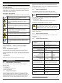 4
4
-
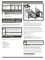 5
5
-
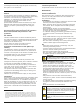 6
6
-
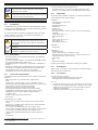 7
7
-
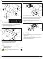 8
8
-
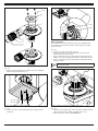 9
9
-
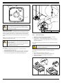 10
10
-
 11
11
-
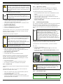 12
12
-
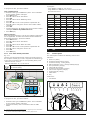 13
13
-
 14
14
-
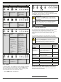 15
15
-
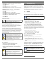 16
16
-
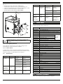 17
17
-
 18
18
-
 19
19
-
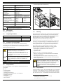 20
20
-
 21
21
-
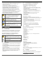 22
22
-
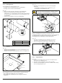 23
23
-
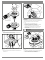 24
24
-
 25
25
-
 26
26
-
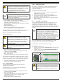 27
27
-
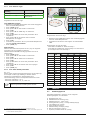 28
28
-
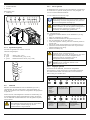 29
29
-
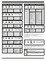 30
30
-
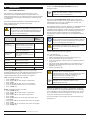 31
31
-
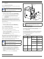 32
32
-
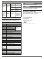 33
33
-
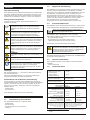 34
34
-
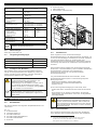 35
35
-
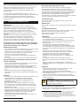 36
36
-
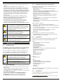 37
37
-
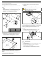 38
38
-
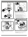 39
39
-
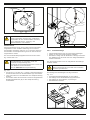 40
40
-
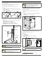 41
41
-
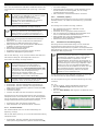 42
42
-
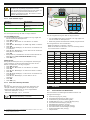 43
43
-
 44
44
-
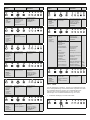 45
45
-
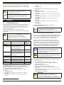 46
46
-
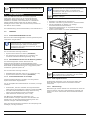 47
47
-
 48
48
-
 49
49
-
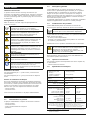 50
50
-
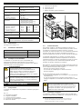 51
51
-
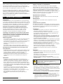 52
52
-
 53
53
-
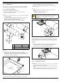 54
54
-
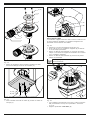 55
55
-
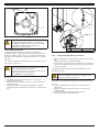 56
56
-
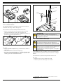 57
57
-
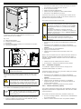 58
58
-
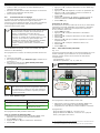 59
59
-
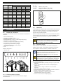 60
60
-
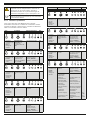 61
61
-
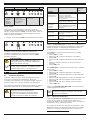 62
62
-
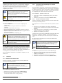 63
63
-
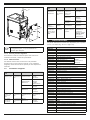 64
64
-
 65
65
-
 66
66
-
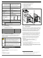 67
67
-
 68
68
-
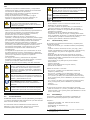 69
69
-
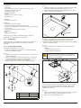 70
70
-
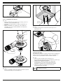 71
71
-
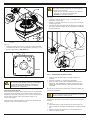 72
72
-
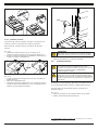 73
73
-
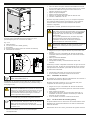 74
74
-
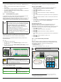 75
75
-
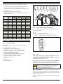 76
76
-
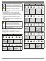 77
77
-
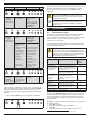 78
78
-
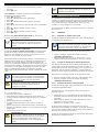 79
79
-
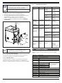 80
80
-
 81
81
-
 82
82
-
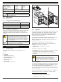 83
83
-
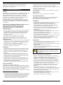 84
84
-
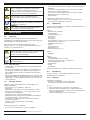 85
85
-
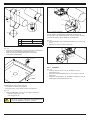 86
86
-
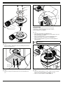 87
87
-
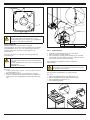 88
88
-
 89
89
-
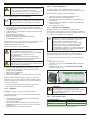 90
90
-
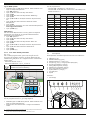 91
91
-
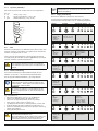 92
92
-
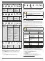 93
93
-
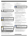 94
94
-
 95
95
-
 96
96
-
 97
97
-
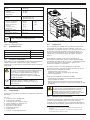 98
98
-
 99
99
-
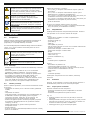 100
100
-
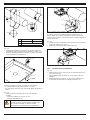 101
101
-
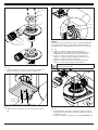 102
102
-
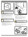 103
103
-
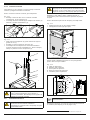 104
104
-
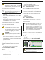 105
105
-
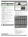 106
106
-
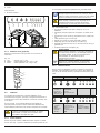 107
107
-
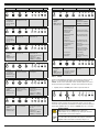 108
108
-
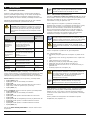 109
109
-
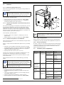 110
110
-
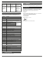 111
111
-
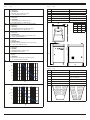 112
112
-
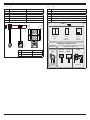 113
113
-
 114
114
-
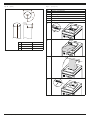 115
115
-
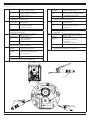 116
116
-
 117
117
-
 118
118


Plymovent Limestone feeder Manual de utilizare
- Tip
- Manual de utilizare
în alte limbi
- français: Plymovent Limestone feeder Manuel utilisateur
- English: Plymovent Limestone feeder User manual
- Deutsch: Plymovent Limestone feeder Benutzerhandbuch
- español: Plymovent Limestone feeder Manual de usuario
- Nederlands: Plymovent Limestone feeder Handleiding
Alte documente
-
Fiamma Compact F80S Manual de utilizare
-
 Eldom Invest 30-150 Household Electric Water Heaters Instrucțiuni de utilizare
-
Milwaukee 950 K Instructions For Use Manual
-
Hendi 208007 Manual de utilizare
-
Milwaukee K 540 S Original Instructions Manual
-
-
Climbing Technology 4A220 Instrucțiuni de utilizare
-
-
-
