Panasonic SCHTB550EB Instrucțiuni de utilizare
- Categorie
- Seturi de difuzoare
- Tip
- Instrucțiuni de utilizare
Acest manual este potrivit și pentru

until
2012/04/30
EG EB GN
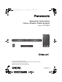
Operating Instructions
Home Theater Audio System
Model No. SC-HTB550
Thank you for purchasing this product.
For optimum performance and safety, please read these instructions carefully.
Please keep this manual for future reference.
Model number suffix “EB” denotes UK models.
RQT9666-1B
SC-HTB550_RQT9666-1B_mst.book Page 1 Monday, March 12, 2012 12:32 PM

2
RQT9666
Table of contents
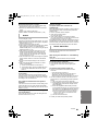
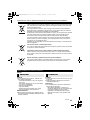
Safety precautions
Unit
≥ To reduce the risk of fire, electric shock or
product damage,
jDo not expose this unit to rain, moisture,
dripping or splashing.
jDo not place objects filled with liquids, such as
vases, on this unit.
jUse only the recommended accessories.
jDo not remove covers.
jDo not repair this unit by yourself. Refer
servicing to qualified service personnel.
AC mains lead
≥ To reduce the risk of fire, electric shock or
product damage,
jEnsure that the power supply voltage
corresponds to the voltage printed on this unit.
jInsert the mains plug fully into the socket
outlet.
jDo not pull, bend, or place heavy items on the
lead.
jDo not handle the plug with wet hands.
jHold onto the mains plug body when
disconnecting the plug.
jDo not use a damaged mains plug or socket
outlet.
≥ Install this unit so that the AC mains lead can be
unplugged from the socket outlet immediately if
any problem occurs.
Button-type battery (Lithium battery)
≥ Risk of fire, explosion and burns. Do not
recharge, disassemble, heat above 60
o
C or
incinerate.
≥ Keep the Button-Type battery out of the reach of
children. Never put Button-Type battery in
mouth. If swallowed call your doctor.
Unit
≥ Do not place sources of naked flames, such as
lighted candles, on this unit.
≥ This unit may receive radio interference caused
by mobile telephones during use. If such
interference occurs, please increase separation
between this unit and the mobile telephone.
≥ This unit is intended for use in moderate
climates.
Placement
≥ Place this unit on an even surface.
≥ To reduce the risk of fire, electric shock or
product damage,
jDo not install or place this unit in a bookcase,
built-in cabinet or in another confined space.
Ensure this unit is well ventilated.
jDo not obstruct this unit’s ventilation openings
with newspapers, tablecloths, curtains, and
similar items.
jDo not expose this unit to direct sunlight, high
temperatures, high humidity, and excessive
vibration.
Button-type battery (Lithium battery)
≥ Danger of explosion if battery is incorrectly
replaced. Replace only with the type
recommended by the manufacturer.
≥ When disposing the batteries, please contact
your local authorities or dealer and ask for the
correct method of disposal.
≥ Insert with poles aligned.
≥ Mishandling of batteries can cause electrolyte
leakage and may cause a fire.
jRemove the battery if you do not intend to use
the remote control for a long period of time.
Store in a cool, dark place.
≥ Do not heat or expose to flame.
≥ Do not leave the battery(ies) in a car exposed to
direct sunlight for a long period of time with
doors and windows closed.
WARNING CAUTION
SC-HTB550_RQT9660_mst.book Page 2 Wednesday, February 1, 2012 6:17 PM

RQT9666
3
Precautions
Caution for AC Mains Lead
(For the United Kingdom and Ireland)
For your safety, please read the following text
carefully.
This appliance is supplied with a moulded three
pin mains plug for your safety and convenience.
A 5-ampere fuse is fitted in this plug.
Should the fuse need to be replaced please
ensure that the replacement fuse has a rating of 5-
ampere and that it is approved by ASTA or BSI to
BS1362.
Check for the ASTA mark Ï or the BSI mark Ì on
the body of the fuse.
If the plug contains a removable fuse cover you
must ensure that it is refitted when the fuse is
replaced.
If you lose the fuse cover the plug must not be
used until a replacement cover is obtained.
A replacement fuse cover can be purchased from
your local dealer.
If a new plug is to be fitted please observe the
wiring code as stated below.
If in any doubt please consult a qualified electrician.
IMPORTANT
The wires in this mains lead are coloured in
accordance with the following code:
Blue: Neutral, Brown: Live.
As these colours may not correspond with the
coloured markings identifying the terminals in your
plug, proceed as follows:
The wire which is coloured Blue must be
connected to the terminal which is marked with the
letter N or coloured Black or Blue.
The wire which is coloured Brown must be
connected to the terminal which is marked with the
letter L or coloured Brown or Red.
WARNING: DO NOT CONNECT EITHER WIRE
TO THE EARTH TERMINAL WHICH IS MARKED
WITH THE LETTER E, BY THE EARTH SYMBOL
Ó
OR COLOURED GREEN OR GREEN/
YELLOW.
THIS PLUG IS NOT WATERPROOF—KEEP
DRY.
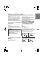
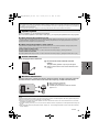
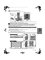
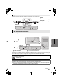
Before use
Remove the connector cover.
How to replace the fuse
The location of the fuse differ according to the type
of AC mains plug (figures A and B). Confirm the AC
mains plug fitted and follow the instructions below.
Illustrations may differ from actual AC mains plug.
1. Open the fuse cover with a screwdriver.
2. Replace the fuse and close or attach the fuse cover.
CAUTION!
IF THE FITTED MOULDED PLUG IS
UNSUITABLE FOR THE SOCKET OUTLET IN
YOUR HOME THEN THE FUSE SHOULD BE
REMOVED AND THE PLUG CUT OFF AND
DISPOSED OF SAFELY.
THERE IS A DANGER OF SEVERE
ELECTRICAL SHOCK IF THE CUT OFF PLUG
IS INSERTED INTO ANY 13-AMPERE SOCKET.
Figure A Figure B
Fuse cover
Figure A Figure B
Fuse
(5 ampere)
Fuse
(5 ampere)
SC-HTB550_RQT9660_mst.book Page 3 Wednesday, February 1, 2012 6:17 PM

4
RQT9666
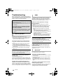
Table of contents
Safety precautions............................................................................................. 2
Caution for AC Mains Lead............................................................................... 3
Before use
Supplied items ................................................................................................... 5
System (SC-HTB550) ......................................................................................................... 5
Accessories......................................................................................................................... 5
Control reference guide .................................................................................... 6
Main unit and active subwoofer (Front)............................................................................... 6
Main unit and active subwoofer (Rear) ............................................................................... 6
Remote control.................................................................................................................... 7
Getting started
Step 1 Selecting the placement method......................................................... 8
Speaker system .................................................................................................................. 9
Active subwoofer................................................................................................................. 9
Wireless interference .......................................................................................................... 9
Step 2 Assembling the speakers................................................................... 10
When attaching the speakers to a wall ............................................................................. 10
When placing the speakers on a table.............................................................................. 14
Additional speaker fall prevention measures .................................................................... 17
Step 3 Connections ........................................................................................ 19
Connection with the TV..................................................................................................... 19
Connection with other devices .......................................................................................... 20
Speaker cable connection................................................................................................. 21
AC mains lead connection ................................................................................................ 21
Active subwoofer wireless connection .............................................................................. 22
Bluetooth
®
connection....................................................................................................... 22
Operations
Using this unit.................................................................................................. 23
3D sound........................................................................................................................... 24
Audio output modes .......................................................................................................... 24
Linked operations with the TV (VIERA Link “HDAVI Control
TM
”)................. 25
Advanced operations ...................................................................................... 26
Reference
Troubleshooting .............................................................................................. 28
Indicator illumination ...................................................................................... 30
Specifications .................................................................................................. 31
Unit care ........................................................................................................... 32
Licenses ........................................................................................................... 32
About Bluetooth
®
............................................................................................. 32
SC-HTB550_RQT9660_mst.book Page 4 Wednesday, February 1, 2012 6:17 PM

Precautions
Reference Getting started
Before useOperations
RQT9666
5
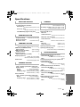
Before use
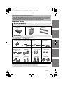
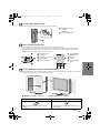
Supplied items
Check the supplied accessories before using the system.
≥ Product numbers are correct as of January 2012. These may be subject to change.
≥ The supplied AC mains lead is for use with this unit and the active subwoofer only.
Do not use it with other equipment. Also, do not use cords from other equipment with this unit or active subwoofer.
≥ The illustrations shown may differ from your unit.
≥ These operation instructions are applicable to model SC-HTB550 for variety of regions.
Unless otherwise indicated, illustrations in these Operating Instructions are of the model for
the United Kingdom and Ireland.
≥ Operations in this Operating Instructions are described mainly with the remote control, but
you can perform the operations on the main unit if the controls are the same.
System (SC-HTB550)
∏ 1Main unit
(SU-HTB550)
∏ 1 Active subwoofer
(SB-HWA550)
∏ 2 Front speakers
(SB-HTB550)
Accessories
∏ 1 Remote control
(with a battery)
(N2QAYC000063)
∏ AC mains lead
2 For the United
Kingdom and Ireland
(K2CZ3YY00024)
2 For Continental
Europe
(K2CQ2CA00007)
2 For Australia and
New Zealand
(K2CJ2DA00008)
∏ 2 Speaker cables
(REEX1266A: RED)
(REEX1267A: WHITE)
Length: 3 m
∏ 1 Speaker joint
(RAQ0085)
∏ 6 Screws
(XYN5+J14FJK)
∏ 2 Speaker feet
(RKAX0028-K)
∏ 2 Front ornaments
(RAQ0089)
∏ 2 Support legs
(RYQ0970-K)
∏ 2Stands
(RYQ0853-KJ)
∏ 2 Speaker bases
(RAQ0086)
SC-HTB550_RQT9660_mst.book Page 5 Wednesday, February 1, 2012 6:17 PM

6
RQT9666
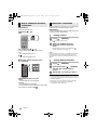
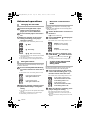
Control reference guide
1 Standby/on switch (Í/I)
Press to switch the unit from on to standby
mode or vice versa. In standby mode, the unit
is still consuming a small amount of power.
2 Adjust the volume of the speakers
3 Select the input source
“TV”#“BD/DVD”#“AUX1”
^--- “”(-- “AUX2”(}
4 Remote control signal sensor (> 7)
5 Input selector indicators
§1
A TV indicator
Lights green when the TV is the audio
source
B BD/DVD indicator
Lights amber when the device connected
to the BD/DVD terminal is the audio
source
C AUX1 indicator
Lights amber when the device connected
to the AUX1 terminal is the audio source
D AUX2 indicator
Lights amber when the device connected
to the AUX2 terminal is the audio source
E Bluetooth
®
indicator
Lights blue when the Bluetooth
®
device is
the audio source
6 Audio format indicators
§1
F Dolby Digital indicator
Lights when Dolby Digital is the current
audio format
G DTS indicator
Lights when DTS is the current audio
format
H PCM indicator
Lights when PCM (2ch, Multi-channel) is
the current audio format
7 WIRELESS LINK indicator (> 22)
1 AC IN terminal (> 21)
2 Speaker terminals (> 21)
3 TV terminal (> 19)
4 AUX2 terminal (> 20)
5 HDMI OUT terminal (ARC compatible) (> 19)
6 BD/DVD terminal (> 20)
7 AUX1 terminal (> 20)
8 Active subwoofer on/off button
§1 The indicators will also blink in various conditions (> 30)
§2 The I/D SET button is only used when the main unit is not paired with the active subwoofer (> 29)
Main unit and active subwoofer (Front)
7
1
2
5
6
3
4
Main unit
Active subwoofer
Main unit and active subwoofer (Rear)
8
1
21 34567
SPEAKERS
6
R L
AV OUT
AV IN
DIGITAL
AUDIO
IN
TV
(OPT1)
AUX2
(OPT2)
TV (ARC)
BD/DVD
(HDMI1)
BD/DVD
(HDMI1)
AUX1
(HDMI2)
AC IN
SC-HTB550_RQT9660_mst.book Page 6 Wednesday, February 1, 2012 6:17 PM

Before use
RQT9666
7
1 Turn the main unit on or off (> 23)
2 Adjust the dialog effect level (> 23)
3 Adjust the output level of the active subwoofer
(bass sound) (> 23)
4 Adjust the volume of this system (> 23)
5 Mute the sound (> 23)
6 Select the TV as the source (> 23)
7 Select the Bluetooth
®
device as the source
(> 23)
8 Select the input source (> 23)
“TV”#“BD/DVD” #“AUX1”
^--- “”(-- “AUX2”(}
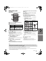
Remote control
DIALOG LEVEL
LINK MODE
PAIRING
----
1
6
7
2
3
4
5
8
INPUT
SELECTOR
Remove the insulation sheet A before using.
∫ To replace a button-type battery
1 While pressing the stopper B, pull out the
battery holder.
2 Set the button-type battery with its (i) mark
facing upward and then put the battery
holder back in place.
≥ When replacing the battery, use:
CR2025 (Lithium battery)
≥ Keep the button-type battery out of reach of
children to prevent swallowing.
∫ Remote control operation range
The remote control signal sensor is located on the main unit.
≥ Use the remote control within the correct operation range.
C Remote control signal sensor
≥ Operation range
Distance: Within approx. 7 m
directly in front
Angle: Approx. 30
o
left and right
SC-HTB550_RQT9660_mst.book Page 7 Wednesday, February 1, 2012 6:17 PM

8
RQT9666
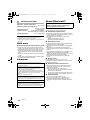
Getting started
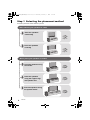
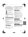
Step 1 Selecting the placement method
≥Choose a placement method that suits you best.
When attaching the speakers to a wall
When placing the speakers on a table
Place the speakers
horizontally
Page 10
Place the speakers
vertically
Place the speakers using
the stands
Place the speakers using
the speaker bases
Page 12
Page 14
Page 15
Page 16
Place the speakers
using the support legs
and speaker feet
SC-HTB550_RQT9660_mst.book Page 8 Wednesday, February 1, 2012 6:17 PM

Getting started
RQT9666
9
≥Use a screwdriver (i) for assembling the speakers.
≥Do not hold the speakers in one hand to avoid injury, you may drop the speakers when carrying them.
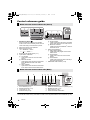
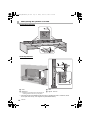
When carrying the active subwoofer
To avoid interference, maintain the following distances between the main unit/active subwoofer
and other electronic devices that use the same radio frequency (2.4 GHz and 5 GHz band).
≥ Place the active subwoofer within a few meters of the main unit and in a horizontal position with the top panel faced upward.
≥ Do not use the main unit or active subwoofer in a metal cabinet.
≥ Placing the active subwoofer and the speakers too close to the walls and corners can result in excessive bass. Cover walls
and windows with thick curtains.
≥ If irregular colouring occurs on your TV, turn the TV off for about 30 minutes. If it persists, move the speakers further away from
the TV.
≥ Keep magnetised items away. Magnetised cards, watches, etc., can be damaged if placed too close to the active subwoofer
and the speakers.
Caution
≥ This system is to be used only as indicated in these instructions. Failure to do so may lead to damage to the amplifier and/or
the speakers, and may result in the risk of fire. Consult a qualified service person if damage has occurred or if you experience
a sudden change in performance.
≥ Do not attempt to attach these speakers to a wall using methods other than those described in this manual.
Speaker system
∫ When attaching the speakers to a wall
The wall or pillar on which the speakers are to be attached should be capable of supporting 33 kg per screw. Consultation with
a qualified installation specialist is recommended when attaching the speakers to a wall. Improper attachment may result in
damage to the wall and speakers, and personal injury.
∫ When placing the speakers in front of the TV
The speakers may block or interfere with the TV’s various sensors (C.A.T.S. (Contrast Automatic Tracking System) sensor,
remote control sensor, etc.) and the 3D Eyewear transmitters on a 3D compatible TV.
≥ If the stands are being used
Move the speakers further away from the TV. If the TV still does not function properly, try removing the stands.
≥ If the stands are not used
Move the speakers further away from the TV. If the TV still does not function properly, try placing them beside the TV (> 8).
Active subwoofer
A Do not hold the active subwoofer from this
opening.
The parts inside (speaker unit) may be damaged.
B Always hold the bottom of the active subwoofer when
moving it.
Wireless interference
C Main unit/active subwoofer
D Wireless LAN: approx. 2 m
E Cordless phone and other electronic devices:
approx. 2 m
A
B
D
E
C
SC-HTB550_RQT9666-1B_mst.book Page 9 Monday, March 12, 2012 12:32 PM

10
RQT9666
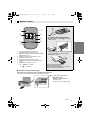
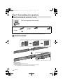
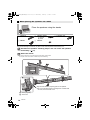
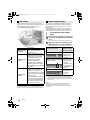
Step 2 Assembling the speakers
≥For a safety measure to prevent the speakers from falling, refer to page 17.
≥To prevent damage or scratches, lay down a soft cloth and perform the assembly on it.
Assemble the speakers.
≥ The two speakers are interchangeable.
When attaching the speakers to a wall
Place the speakers horizontally
∏ 2 Speakers ∏ 2 Speaker cables
(L): WHITE
(R): RED
∏ 1 Speaker joint
∏ 4 Screws
A
“”
shaped slit
≥ Insert the speaker joint fully into the slit.
B Screw (supplied)
≥ Be sure to insert the screws following the order as indicated in the illustration.
≥ Keep the screws out of reach of children to prevent swallowing.
2
4
1
3
SC-HTB550_RQT9660_mst.book Page 10 Wednesday, February 1, 2012 6:17 PM

Getting started
RQT9666
11
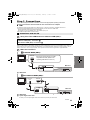
Connect the speaker cables.
≥ Use the “Panasonic” logo to identify the left and right speakers, then connect the cables (as illustrated).
≥ Insert the wire fully, taking care not to insert beyond the wire insulation.
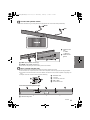
Drive a screw into the wall.
≥ Use the measurements indicated below to identify the screwing positions on the wall.
≥ Leave at least 20 mm of space above and on each side of the speaker to allow enough space for fitting the speaker.
≥ The position on the wall where the screw is to be attached, as well as the screw, should be capable of supporting over
33 kg.
≥ Keep the screws out of reach of children to prevent swallowing.
1 Insert the wire
fully.
r: White
s: Blue line
2 Press into the
groove.
A RED: Right speaker channel (R)
B WHITE: Left speaker channel (L)
C At least 30 mm
D ‰4.0 mm
E ‰7.0 mm to ‰9.4 mm
F Wall or pillar
G 5.5 mm to 6.5 mm
H 326 mm I 316 mm J 316 mm K 26 mm
L Wall mounting hole
White
Red
Push
Front view (semi-transparent image)
SC-HTB550_RQT9660_mst.book Page 11 Wednesday, February 1, 2012 6:17 PM

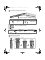
12
RQT9666
Fit the speaker securely onto the screw(s).
≥For a safety measure to prevent the speakers from falling, refer to page 17.
≥To prevent damage or scratches, lay down a soft cloth and perform the assembly on it.
Attach the front ornaments.
≥ The two speakers are interchangeable.
≥ Keep the screws out of reach of children to prevent swallowing.
DO DO NOT
≥ Move the speaker so
that the screw is in this
position.
≥ In this position, the
speaker will likely fall if
moved to the left or right.
Place the speakers vertically
∏ 2 Speakers ∏ 2 Speaker cables
(L): WHITE
(R): RED
∏ 2 Front ornaments
∏ 4 Screws
Front view
Rear view
SC-HTB550_RQT9660_mst.book Page 12 Wednesday, February 1, 2012 6:17 PM

Getting started
RQT9666
13
Connect the speaker cables.
≥ Insert the wire fully, taking care not to insert beyond the wire insulation.
Drive a screw into the wall.
≥ Use the measurements indicated below to identify the screwing positions on the wall.
≥ Leave at least 20 mm of space above and on each side of the speaker to allow enough space for fitting the speaker.
≥ The position in the wall where the screw is to be attached as well as the screw should be capable of supporting over
33 kg.
≥ Keep the screws out of reach of children to prevent swallowing.
Fit the speaker(s) securely onto the screw(s).
≥ Place the speaker that is connected with the speaker cable with a red connector on the observers’ right, and connect with
the speaker cable with a white connector on the observers’ left.
1 Insert the wire fully.
r: White
s: Blue line
2 Press into the groove.
A At least 30 mm
B ‰4.0 mm
C ‰7.0 mm to ‰9.4 mm
D Wall or pillar
E 5.5 mm to 6.5 mm
F Front speaker
(Rear view)
G 102 mm
H 37 mm
I Wall mounting
hole
J WHITE: Left speaker channel (L) K RED: Right speaker channel (R)
DO DO NOT
≥ Move the speaker so that the screw is in this
position.
≥ In this position, the speaker will likely fall if moved to
the left or right.
Push
Red
White
SC-HTB550_RQT9660_mst.book Page 13 Wednesday, February 1, 2012 6:17 PM

14
RQT9666
≥For a safety measure to prevent the speakers from falling, refer to page 17.
≥To prevent damage or scratches, lay down a soft cloth and perform the assembly on it.
Assemble the speakers following steps 1 and 2 of “Place the speakers
horizontally” (> 10).
Attach the stands.
≥ Use the “Panasonic” logo to identify the top and bottom of the speaker.
≥ Keep the screws out of reach of children to prevent swallowing.
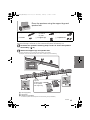
When placing the speakers on a table
Place the speakers using the stands
∏ 2 Speakers ∏ 2 Speaker cables
(L): WHITE
(R): RED
∏ 1 Speaker joint
∏ 2 Stands ∏ 6 Screws
A Screw (supplied)
B Screw hole
Align the holes with the projecting parts on the speaker.
≥ Do not use the lower holes for the alignment. If these holes
are used, the screw does not fit.
SC-HTB550_RQT9660_mst.book Page 14 Wednesday, February 1, 2012 6:17 PM

Getting started
RQT9666
15
≥For a safety measure to prevent the speakers from falling, refer to page 17.
≥To prevent damage or scratches, lay down a soft cloth and perform the assembly on it.
Assemble the speakers following steps 1 and 2 of “Place the speakers
horizontally” (> 10).
Attach the support legs and speaker feet.
≥ Use the “Panasonic” logo to identify the top and bottom of the speaker.
≥ Keep the screws and the speaker feet out of reach of children to prevent swallowing.
Place the speakers using the support legs and
speaker feet
∏ 2 Speakers ∏ 2 Speaker cables
(L): WHITE
(R): RED
∏ 1 Speaker joint
∏ 6 Screws ∏ 2 Support legs ∏ 2 Speaker feet
A Screw (supplied)
B Screw hole
C Speaker foot (supplied)
≥ Attach the speaker foot directly below the wall mounting hole (as illustrated).
Align the
projecting parts
on the speaker
with support leg.
SC-HTB550_RQT9660_mst.book Page 15 Wednesday, February 1, 2012 6:17 PM

16
RQT9666
≥For a safety measure to prevent the speakers from falling, refer to page 17.
≥To prevent damage or scratches, lay down a soft cloth and perform the assembly on it.
Assemble the speakers following step 1 of “Place the speakers
vertically” (> 12).
Insert the speaker cable through the base.
≥ Be sure to insert the speaker cable through the threading hole as indicated in the illustration. (If the speaker cable is
twisted, it might not fit through the opening. Straighten the speaker cable before inserting.)
Attach the speaker to the base.
≥ The two speakers are interchangeable.
≥ Keep the screws out of reach of children to prevent swallowing.
Place the speakers using the speaker
bases
∏ 2 Speakers ∏ 2 Speaker cables
(L): WHITE
(R): RED
∏ 2 Bases
∏ 2 Front ornaments ∏ 6 Screws
A Threading hole B Screw hole
Position the cable
between the ridges.
≥ Leave about
110 mm
Screw (supplied)
≥ Tighten securely.
Align the projecting parts with the holes on the speaker.
SC-HTB550_RQT9660_mst.book Page 16 Wednesday, February 1, 2012 6:17 PM

Getting started
RQT9666
17
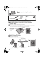
Connect the speaker cables.
≥ Insert the wire fully, taking care not to insert beyond the wire insulation.
≥ Place the speaker that is connected with the speaker cable with a red connector on the observers’ right, and connect with
the speaker cable with a white connector on the observers’ left.
To prevent the speakers from falling, it is recommended, as an additional
protection measure, to attach the speakers to the wall or table with a fall
prevention cord (hereafter “cord”).
≥ Consultation with a qualified installation specialist concerning the appropriate procedure when attaching to a concrete wall or a
surface that may not have strong enough support is recommended (> 11, 13). Improper attachment may result in damage to
the wall and speakers, and personal injury.
≥ Use a cord that is capable of supporting over 10 kg (with a diameter of about 1.5 mm).
≥ Keep the screws out of reach of children to prevent swallowing.
≥ Make sure that the slack of the cord is minimal.
Additional speaker fall prevention measures
When attaching the speakers to a wall
A Cord
§
B Screw eye C Wall D Wall-mounted speakers
§ If the cord cannot be threaded through the holes, try bending the cord in 2 locations, about
10 mm apart from the tip, at an angle of 45
o
(as
illustrated above).
Insert the
wire fully.
r: White
s: Blue line
Press into the groove.
Push
Back of the base
Horizontal placement
Vertical placement
SC-HTB550_RQT9666-1B_mst.book Page 17 Monday, March 12, 2012 12:32 PM

18
RQT9666
When placing the speakers on a table
Horizontal placement
Vertical placement
A Cord
§
B Screw eye
≥ Depending on the placement of the speakers, the
screwing position of the screw eye may differ.
C Wall
D Approx. 150 mm
§ If the cord cannot be threaded through the holes, try bending the cord in 2 locations, about
10 mm apart from the tip, at an angle of 45
o
(as
illustrated above).
SC-HTB550_RQT9666-1B_mst.book Page 18 Monday, March 12, 2012 12:32 PM

Getting started
RQT9666
19
Step 3 Connections
≥Turn off all equipment before connection and read the appropriate operating instructions.
Do not connect the AC mains lead until all other connections are complete.
∫ HDMI
The HDMI connection supports VIERA Link “HDAVI Control” (> 25) when used with a compatible Panasonic TV.
≥ Use the High Speed HDMI Cables. It is recommended that you use Panasonic’s HDMI cable.
Recommended part number (High Speed HDMI cable):
RP-CDHS15 (1.5 m), RP-CDHS30 (3.0 m), RP-CDHS50 (5.0 m), etc.
≥ Non-HDMI-compliant cables cannot be utilised.
Verify if the TV’s HDMI terminal is labelled “HDMI (ARC)”.
∫ What is ARC?
ARC is an abbreviation of Audio Return Channel, also known as HDMI ARC. It refers to one of the HDMI functions. When you
connect the main unit to the terminal labelled “HDMI (ARC)”, the optical digital audio cable that is usually required in order to
listen to sound from a TV is no longer required, and TV pictures and sound can be enjoyed with a single HDMI cable.
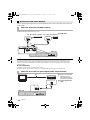
Make the connection.
Connection with the TV
Connection differs depending on the label printed next to the HDMI terminal.
Labelled “HDMI (ARC)”: Connection [A]
Not Labelled “HDMI (ARC)”: Connection [B]
[A] Labelled “HDMI (ARC)”
A HDMI cable
[B] Not labelled “HDMI (ARC)”
A HDMI cable
B Optical digital audio cable
≥ When you use the optical digital audio cable, insert the tip correctly into the terminal.
SPEAKERS / HAUT-PARLEURS
AV OUT
DIGITAL
AUDIO
IN
TV (ARC)
AC IN
HDMI IN
(ARC)
AV IN
TV (ARC)
BD/DVD
(HDMI1)
BD/DVD
(HDMI1)
AUX1
(HDMI2)
AV OUT
TV
Main unit
Be sure to connect to the TV’s ARC
compatible terminal. (Refer to the
operating instructions for the TV.)
SPEAKERS / HAUT-PARLEURS
6
R
L
AV OUT
DIGITAL
AUDIO
IN
TV
(OPT1)
TV (ARC)
AC IN
HDMI IN
OPTICAL
OUT
TV (ARC)
AV OUT
DIGITAL
AUDIO
IN
TV
(OPT1)
TV
Main unit
SC-HTB550_RQT9660_mst.book Page 19 Wednesday, February 1, 2012 6:17 PM

20
RQT9666
You can direct the audio signal from the connected Blu-ray Disc
TM
player, DVD player, Set Top Box, etc.
to this system.
Preparation
≥Connect the main unit to the TV (> 19).
∫ HDMI standby pass-through
Even if the main unit is in standby mode, the audio and/or video signal from the device connected to the BD/DVD or AUX1
terminal will be sent to the TV connected to the HDMI OUT terminal (the sound will not be output from this system). When
devices are connected to both BD/DVD and AUX1 terminals, audio and/or video signal of the device whose input is lastly
selected is output.
∫ 3D compatibility
Compatible with FULL HD 3D TV and Blu-ray Disc
TM
player.
≥ The main unit can pass the 3D video signal from a 3D compatible Blu-ray Disc
TM
player to a FULL HD 3D TV.
Connection with other devices
When the device has an HDMI terminal
A HDMI cable
When the device has an optical digital audio output terminal
B Refer to the operating
instructions of the
respective devices for
the optimal connection
C Optical digital audio
cable
HDMI OUT
HDMI OUT
SPEAKERS
AV IN
DIGITAL
AUDI O
IN
BD/DVD
(HDMI1)
BD/DVD
(HDMI1)
AUX1
(HDMI2)
AC IN
AV IN
BD/DVD
(HDMI1)
BD/DVD
(HDMI1)
AUX1
(HDMI2)
e.g., Video game console
Main unit
e.g., Blu-ray Disc
TM
player
OPTICAL OUT
SPEAKERS
DIGITAL
AUDIO
IN
AUX2
(OPT2)
AC IN
DIGITAL
AUDIO
IN
AUX2
(OPT2)
e.g., Set top box
Main unit
TV
SC-HTB550_RQT9660_mst.book Page 20 Wednesday, February 1, 2012 6:17 PM
Pagina se încarcă...
Pagina se încarcă...
Pagina se încarcă...
Pagina se încarcă...
Pagina se încarcă...
Pagina se încarcă...
Pagina se încarcă...
Pagina se încarcă...
Pagina se încarcă...
Pagina se încarcă...
Pagina se încarcă...
Pagina se încarcă...
Pagina se încarcă...
Pagina se încarcă...
Pagina se încarcă...
Pagina se încarcă...
-
 1
1
-
 2
2
-
 3
3
-
 4
4
-
 5
5
-
 6
6
-
 7
7
-
 8
8
-
 9
9
-
 10
10
-
 11
11
-
 12
12
-
 13
13
-
 14
14
-
 15
15
-
 16
16
-
 17
17
-
 18
18
-
 19
19
-
 20
20
-
 21
21
-
 22
22
-
 23
23
-
 24
24
-
 25
25
-
 26
26
-
 27
27
-
 28
28
-
 29
29
-
 30
30
-
 31
31
-
 32
32
-
 33
33
-
 34
34
-
 35
35
-
 36
36


Panasonic SCHTB550EB Instrucțiuni de utilizare
- Categorie
- Seturi de difuzoare
- Tip
- Instrucțiuni de utilizare
- Acest manual este potrivit și pentru
în alte limbi
Lucrări înrudite
-
Panasonic SCHTB500 - HOME THEATER AUDIO SYSTEM Operating Instructions Manual
-
Panasonic SCHTB258EB Manualul proprietarului
-
-
-
Panasonic SCHTB527EG Manualul proprietarului
-
-
-
-
-