ELICA Hidden Ix/A/90 Manual de utilizare
- Categorie
- Hote pentru aragaz
- Tip
- Manual de utilizare

IT Istruzioni di montaggio e d'uso
EN Instruction on mounting and use
DE Montage- und Gebrauchsanweisung
FR Prescriptions de montage et mode d’emploi
NL Montagevoorschriften en gebruiksaanwijzingen
ES Montaje y modo de empleo
PT Instruções para montagem e utilização
EL
SV Monterings- och bruksanvisningar
FI Asennus- ja käyttöohjeet
NO Instrukser for montering og bruk
DA Bruger- og monteringsvejledning
PL Instrukcja montau i obsugi
CS Návod na montáž a používání
SK Návod k montáži a užití
HU Felszerelési és használati utasítás
BG
RO INSTRUCTII DE MONTAJ SI FOLOSIRE
RU
UK
ET Paigaldus- ja kasutusjuhend
LT montavimo ir naudojimosi instrukcija
LV ierkošanas un izmantošanas instrukcija
SR Uputstva za montažu i upotrebu
SL Navodila za montažo in uporabo
HR Uputstva za montažu i za uporabu
TR Montaj ve kullanım talimatları
AR


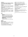
1
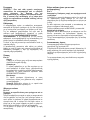
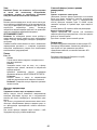
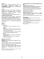
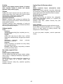
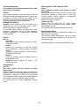
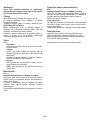
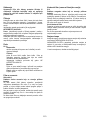
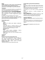
60cm
90cm
493
260
+2
+2
693
260
+2
+2

Ø 150mm
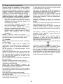
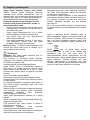
2
3
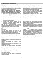
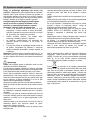
2 x
Ø 3,5x9,5mm

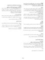
4
5

4 x
16mm
> 20
4 x
10mm
= 15
< 20
4 x
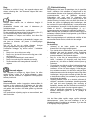
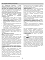
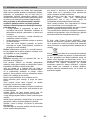
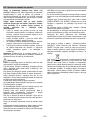
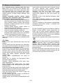
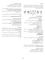
6
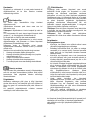
7

8
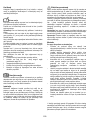
*
1
2
9
*

stunk!
clack!
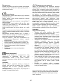
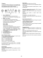
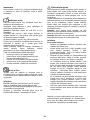
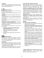
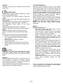
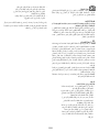
11
10

2
1
clack!
clack!
12
13

10
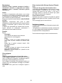
IT - Istruzioni di montaggio e d'uso
Attenersi strettamente alle istruzioni riportate in questo
manuale. Si declina ogni responsabilità per eventuali
inconvenienti, danni o incendi provocati all'apparecchio
derivati dall'inosservanza delle istruzioni riportate in questo
manuale. La cappa è concepita per l'aspirazione dei fumi e
vapori della cottura ed è destinata al solo uso domestico.
La cappa può avere estetiche differenti rispetto a quanto
illustrato nei disegni di questo libretto, comunque le
istruzioni per l'uso, la manutenzione e l'installazione
rimangono le stesse.
! E' importante conservare questo manuale per poterlo
consultare in ogni momento. In caso di vendita, di
cessione o di trasloco, assicurarsi che resti insieme al
prodotto.
! Leggere attentamente le istruzioni: ci sono importanti
informazioni sull'installazione, sull'uso e sulla sicurezza.
! Non effettuare variazioni elettriche o meccaniche sul
prodotto o sulle condotte di scarico.
! Prima di procedere nell'installazione dell'apparecchio
verificare che tutti i componenti non siano danneggiati. In
caso contrario contattare il rivenditore e non proseguire
con l'installazione.
Nota: I particolari contrassegnati con il simbolo "(*)" sono
accessori opzionali forniti solo in alcuni modelli o particolari
non forniti, da acquistare.
Avvertenze
Attenzione! Non collegare l’apparecchio alla rete elettrica
finche l’installazione non è totalmente completata.
Prima di qualsiasi operazione di pulizia o manutenzione,
disinserire la cappa dalla rete elettrica togliendo la spina o
staccando l’interruttore generale dell’abitazione.
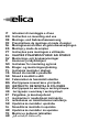
Per tutte le operazioni di installazione e manutenzione
utilizzare guanti da lavoro
L’apparecchio non è destinato all’utilizzo da parte di bambini o
persone con ridotte capacità fisiche sensoriali o mentali e con
mancata esperienza e conoscenza a meno che essi non siano
sotto la supervisione o istruiti nell’uso dell’apparecchiatura da
una persona responsabile per la loro sicurezza.
I bambini devono essere controllati affinché non giochino con
l’apparecchio.
Mai utilizzare la cappa senza griglia correttamente montata!
La cappa non va MAI utilizzata come piano di appoggio a
meno che non sia espressamente indicato.
Il locale deve disporre di sufficiente ventilazione, quando la
cappa da cucina viene utilizzata contemporaneamente ad altri
apparecchi a combustione di gas o altri combustibili.
L’aria aspirata non deve essere convogliata in un condotto
usato per lo scarico dei fumi prodotti da apparecchi a
combustione di gas o di altri combustibili.
E’ severamente vietato fare cibi alla fiamma sotto la cappa.
L’impiego di fiamma libera è dannoso ai filtri e può dar luogo
ad incendi, pertanto deve essere evitato in ogni caso.
La frittura deve essere fatta sotto controllo onde evitare che
l’olio surriscaldato prenda fuoco.
Quando il piano di cottura è in funzione le parti accessibili
della cappa possono diventare calde.
Per quanto riguarda le misure tecniche e di sicurezza da
adottare per lo scarico dei fumi attenersi strettamente a
quanto previsto dai regolamenti delle autorità locali
competenti.
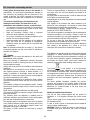
La cappa va frequentemente pulita sia internamente che
esternamente (ALMENO UNA VOLTA AL MESE, rispettare
comunque quanto espressamente indicato nelle istruzioni di
manutenzione riportate in questo manuale).
L’inosservanza delle norme di pulizia della cappa e della
sostituzione e pulizia dei filtri comporta rischi di incendi.
Non utilizzare o lasciare la cappa priva di lampade
correttamente montate per possibile rischio di scossa elettrica.
Si declina ogni responsabilità per eventuali inconvenienti,
danni o incendi provocati all’apparecchio derivati
dall’inosservanza delle istruzioni riportate in questo manuale.
Questo apparecchio è contrassegnato in conformità alla
Direttiva Europea 2002/96/EC, Waste Electrical and Electronic
Equipment (WEEE). Assicurandosi che questo prodotto sia
smaltito in modo corretto, l'utente contribuisce a prevenire le
potenziali conseguenze negative per l'ambiente e la salute.
Il simbolo
sul prodotto o sulla documentazione di
accompagnamento indica che questo prodotto non deve
essere trattato come rifiuto domestico ma deve essere
consegnato presso l'idoneo punto di raccolta per il riciclaggio
di apparecchiature elettriche ed elettroniche. Disfarsene
seguendo le normative locali per lo smaltimento dei rifiuti. Per
ulteriori informazioni sul trattamento, recupero e riciclaggio di
questo prodotto, contattare l'idoneo ufficio locale, il servizio di
raccolta dei rifiuti domestici o il negozio presso il quale il
prodotto è stato acquistato.

11
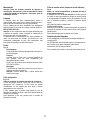
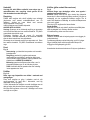
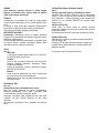
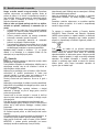
Utilizzazione
La cappa è realizzata per essere utilizzata in versione
aspirante ad evacuazione esterna o filtrante a ricircolo interno.
Versione aspirante
I vapori vengono evacuati verso l’esterno tramite un tubo di
scarico fissato alla flangia di raccordo.
Il diametro del tubo di scarico deve essere equivalente al
diametro dell'anello di connessione.
Attenzione! Il tubo di evacuazione non è fornito e va
acquistato.
Nella parte orizzontale, il tubo deve avere una leggera
inclinazione verso l’alto (10° circa) in modo da poter
trasportare l’aria verso l’esterno più facilmente.
Se la cappa è provvista di filtri al carbone, questi devono
essere tolti.
Collegare la cappa a tubi e fori di scarico a parete con
diametro equivalente all'uscita d'aria (flangia di raccordo).
L'utilizzo di tubi e fori di scarico a parete con diametro inferiore
determinerà una diminuizione delle prestazioni di aspirazione
ed un drastico aumento della rumorosità.
Si declina perciò ogni responsabilità in merito.
! Usare un condotto lungo il minimo indispensabile.
! Usare un condotto con minor numero di curve possibile
(angolo massimo della curva: 90°).
! Evitare cambiamenti drastici di sezione del condotto.
! Usare un condotto con l’interno più liscio possibile.
! Il materiale del condotto deve essere approvato
normativamente.
Versione filtrante
L’aria aspirata verrà sgrassata e deodorata prima di essere
riconvogliata nella stanza. Per utilizzare la cappa in questa
versione è necessario installare un sistema di filtraggio
aggiuntivo a base di carboni attivi.
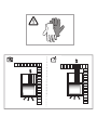
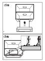
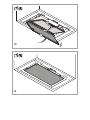
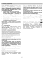
Installazione
La distanza minima fra la superficie di supporto dei recipienti
sul dispositivo di cottura e la parte più bassa della cappa da
cucina deve essere non inferiore a 50cm in caso di cucine
elettriche e di 65cm in caso di cucine a gas o miste.
Se le istruzioni di installazione del dispositivo di cottura a gas
specificano una distanza maggiore, bisogna tenerne conto.
Collegamento Elettrico
La tensione di rete deve corrispondere alla tensione riportata
sull’etichetta caratteristiche situata all’interno della cappa. Se
provvista di spina allacciare la cappa ad una presa conforme
alle norme vigenti posta in zona accessibile anche dopo
l’installazione. Se sprovvista di spina (collegamento diretto
alla rete) o la spina non è posta in zona accessibile, anche
dopo installazione, applicare un interruttore bipolare a norma
che assicuri la disconnessione completa della rete nelle
condizioni della categoria di sovratensione III, conformemente
alle regole di installazione.
Attenzione! Prima di ricollegare il circuito della cappa
all’alimentazione di rete e di verificarne il corretto
funzionamento, controllare sempre che il cavo di rete sia stato
montato correttamente.
Attenzione! La sostituzione del cavo di alimentazione deve
essere effettuata dal servizio assistenza tecnica autorizzato o
da persona con qualifica similare.
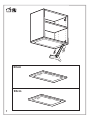
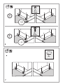
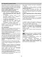
Montaggio
Prima di iniziare con l'installazione:
• Verificare che il prodotto acquistato sia di dimensioni
idonee alla zona di installazione prescelta.
• Togliere il/i filtro/i al carbone attivo se forniti (vedi anche
paragrafo relativo). Questo/i va/nno rimontato/i solo se si
vuole utilizzare la cappa in versione filtrante.
• Verificare che all'interno della cappa non vi sia (per motivi
di trasporto) materiale di corredo (ad esempio buste con
viti, garanzie etc) , eventualmente va tolto e conservato.
• Se possibile scollegare e rimuovere i mobili sottostanti ed
intorno l’area di installazione (parete o soffitto) della
cappa in modo da avere una migliore accessibilità.
Altrimenti proteggere per quanto possibile i mobili e tutte
le parti interessate all'installazione. Scegliere una
superficie piatta da coprire con una protezione dove poi
appoggiare la cappa e i particolari a corredo.
• Verificare inoltre che in prossimità della zona di
installazione della cappa (in zona accessibile anche con
cappa montata) sia disponibile una presa elettrica e sia
possibile collegarsi ad un dispositivo di scarico fumi
verso l'esterno (solo Versione aspirante).
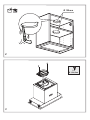
• Eseguire tutti i lavori di muratura necessari (ad es.:
installazione di una presa elettrica e/o foro per il
passaggio del tubo di scarico).
Nel caso della presenza di pannelli e/o pareti e/o pensili
laterali, verificare che ci sia spazio sufficiente per installare la
cappa e che sia sempre possibile accedere al pannello
comandi con facilità.

12
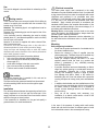
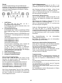
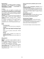
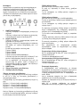
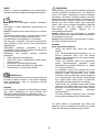
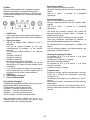
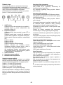
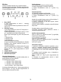
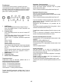
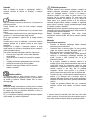
Funzionamento
Usare la velocità maggiore in caso di particolare
concentrazione di vapori di cucina. Consigliamo di accendere
l'aspirazione 5 minuti prima di iniziare a cucinare e di lasciarla
in funzione a cottura terminata per altri 15 minuti circa.
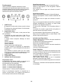
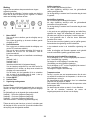
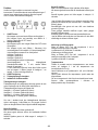
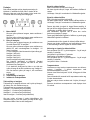
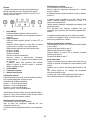
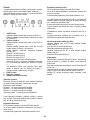
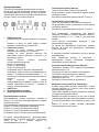
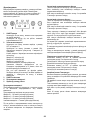
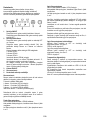
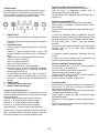
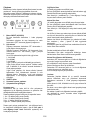
1 ON/OFF motore
Premendo il pulsante la cappa si avvia alla velocità 1.
Premendo il pulsante durante il funzionamento la cappa
passa in stato OFF.
2 Incremento velocità
Premendo il pulsante la cappa passa dallo stato OFF alla
velocità 1.
Premendo il pulsante (cappa in stato ON) viene
incrementata la velocità del motore dalla velocità 1 alla
intensiva.
Ad ogni velocità corrisponde l’accensione del rispettivo
led.
Velocità 1 led L1
Velocità 2 led L2
Velocità 3 led L3
Velocità intensiva led L4 (lampeggiante)
La velocità intensiva è temporizzata. La temporizzazione
standard è di 5’, alla fine della quale la cappa si
posiziona alla velocità 2.
Per disattivare la funzione prima dello scadere del tempo
premere il tasto 2, la cappa si posizionerà alla velocità 1,
premendo il tasto 1 la cappa si spegnerà.
3 ON/OFF luci
4 Temporizzazione velocità
5 Indicatore stato di funzionamento
Temporizzazione velocità
La temporizzazione delle velocità si abilita premendo il tasto
4, a temporizzazione scaduta la cappa si spegne.
La temporizzazione è così suddivisa:
Velocità 1 - 20 minuti (led L1 lampeggiante)
Velocità 2 - 15 minuti (led L2 lampeggiante)
Velocità 3 - 10 minuti (led L3 lampeggiante)
Velocità intensiva - 5 minuti (led L4 lampeggiante)
Durante il funzionamento temporizzato premendo il tasto 1 la
cappa si spegne, se si preme il tasto 2 o il tasto 4 la cappa
torna alla velocità impostata.
Segnalazione filtro grassi
Dopo 40 ore di funzionamento il led L5 si accende.
Quando compare tale segnalazione il filtro grassi installato
necessita di essere lavato.
Per resettare la segnalazione tenere premuto il tasto 1 per 3”.
Segnalazione filtro carboni
Dopo 160 ore di funzionamento il led L5 lampeggia.
Quando compare tale segnalazione il filtro carboni installato
deve essere sostituito.
Per resettare la segnalazione tenere premuto il tasto 1 per 3”.
Nel caso di segnalazione contemporanea di entrambi i filtri, il
led L5 indicherà alternativamente gli allarmi rimanendo
acceso per 3" e lampeggiando successivamente per 3 volte.
Il reset avviene effettuando 2 volte la procedera sopra
descritta.
La prima volta resetta la segnalazione del filtro grassi, la
seconda resetta la segnalazione del filtro carboni.
Nella modalità standard la segnalazione filtro carboni non è
attiva.
Nel caso si utilizzi la cappa in versione filtrante è necessario
abilitare la segnalazione filtro carboni.
Attivazione segnalazione filtro carboni:
Posizionare la cappa in OFF e tenere premuti
contemporaneamente i tasti 1 e 4 per 3”.
I led L1 e L2 lampeggeranno per 5”.
Disattivazione segnalazione filtro carboni:
Posizionare la cappa in OFF e tenere premuti
contemporaneamente i tasti 1 e 4 per 3”.
Il led L1 lampeggerà per 2”.
Allarme Temperatura
La cappa è equipaggiata con un sensore di temperatura che
attiva il motore alla velocità 3 nel caso in cui la temperatura
nella zona comandi sia troppo elevata.
La condizione di allarme viene indicata con il lampeggio in
sequenza dei led L1, L2, L3.
Questa condizione permane fino a quando la temperatura non
scende al di sotto della soglia di allarme.
Si può uscire da questa modalità premendo il tasto 1 o 2.
Ogni 30” il sensore verifica la temperatura ambiente della
zona display.

13
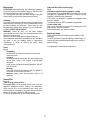
Manutenzione
Attenzione! Prima di qualsiasi operazione di pulizia o
manutenzione, disinserire la cappa dalla rete elettrica
togliendo la spina o staccando l’interruttore generale
dell’abitazione.
Pulizia
La cappa va frequentemente pulita (almeno con la stessa
frequenza con cui si esegue la manutenzione dei filtri grassi),
sia internamente che esternamente. Per la pulizia usare un
panno inumidito con detersivi liquidi neutri.
Evitare l’uso di prodotti contenenti abrasivi. NON UTILIZZARE
ALCOOL!
Attenzione: L’inosservanza delle norme di pulizia
dell’apparecchio e della sostituzione dei filtri comporta rischi di
incendi. Si raccomanda quindi di attenersi alle istruzioni
suggerite.
Si declina ogni responsabilità per eventuali danni al motore,
incendi provocati da un’impropria manutenzione o
dall’inosservanza delle suddette avvertenze.
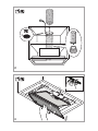
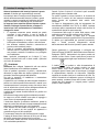
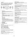
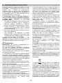
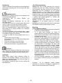
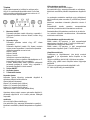
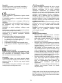
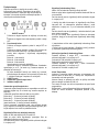
Pannello
Fig. 10
Smontaggio:
tirare il pannello con decisione verso l'esterno e
sganciarlo da tutti i punti di aggancio.
Pulizia:
il pannello va pulito con la stessa frequenza del filtro
grassi, usare un panno inumidito con detersivi liquidi
neutri.
Evitare l’uso di prodotti contenenti abrasivi. NON
UTILIZZARE ALCOOL!
Montaggio :
Il pannello va fissato ad incastro nei perni posti allo
scopo sulla superfice della cappa.
Attenzione! verificare sempre che il pannello sia ben
fissato al suo posto.
Filtro antigrasso
Fig. 8-11
Trattiene le particelle di grasso derivanti dalla cottura.
Il filtro antigrasso metallico deve essere pulito una volta al
mese con detergenti non aggressivi, manualmente oppure in
lavastoviglie a basse temperature ed a ciclo breve.
Con il lavaggio in lavastoviglie il filtro antigrasso metallico può
scolorirsi ma le sue caratteristiche di filtraggio non cambiano
assolutamente.
Per smontare il filtro grassi tirare la maniglia di sgancio a
molla.
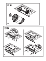
Filtro ai carboni attivi (Solo per Versione Filtrante)
Fig. 9
Trattiene gli odori sgradevoli derivanti dalla cottura.
La saturazione del filtro carbone si verifica dopo un uso più o
meno prolungato a seconda del tipo di cucina e della
regolarità della pulizia del filtro grassi. In ogni caso è
necessario sostituire la cartuccia al massimo ogni quattro
mesi. NON può essere lavato o rigenerato
Filtro al carbone circolare
Applicarne uno per lato a copertura di entrambe le griglie di
protezione della girante del motore, dopodiche girare in senso
orario.
Per lo smontaggio girare in senso antiorario.
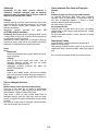
Sostituzione Lampade
La cappa è dotata di un sistema di illuminazione basato sulla
tecnologia LED.
I LED garantiscono una illuminazione ottimale, una durata fino
a 10 volte maggiore delle lampade tradizionali e consentono
di risparmiare il 90% di energia elettrica.
Per la sostituzione rivolgersi al servizio assistenza tecnica.

14
EN - Instruction on mounting and use
Closely follow the instructions set out in this manual. All
responsibility, for any eventual inconveniences, damages or
fires caused by not complying with the instructions in this
manual, is declined. The hood is conceived for the suction of
cooking fumes and steam and is destined only for domestic
use.
The hood can look different to that illustrated in the
drawings in this booklet. The instructions for use,
maintenance and installation, however, remain the same.
! It is important to conserve this booklet for consultation at
any moment. In the case of sale, cession or move, make
sure it is together with the product.
! Read the instructions carefully: there is important
information about installation, use and safety.
! Do not carry out electrical or mechanical variations on the
product or on the discharge conduits.
! Before proceeding with the installation of the appliance
verify that there are no damaged all components.
Otherwise contact your dealer and do not proceed with
the installation.
Note: the elements marked with the symbol “(*)” are optional
accessories supplied only with some models or elements to
purchase, not supplied.
Caution
WARNING! Do not connect the appliance to the mains until
the installation is fully complete.
Before any cleaning or maintenance operation, disconnect
hood from the mains by removing the plug or disconnecting
the mains electrical supply.
Always wear work gloves for all installation and maintenance
operations.
The appliance is not intended for use by children or persons
with impaired physical, sensorial or mental faculties, or if
lacking in experience or knowledge, unless they are under
supervision or have been trained in the use of the appliance
by a person responsible for their safety.
This appliance is designed to be operated by adults, children
should be monitored to ensure that they do not play with the
appliance.
This appliance is designed to be operated by adults. Children
should not be allowed to tamper with the controls or play with
the appliance.
Never use the hood without effectively mounted grating!
The hood must NEVER be used as a support surface unless
specifically indicated.
The premises where the appliance is installed must be
sufficiently ventilated, when the kitchen hood is used together
with other gas combustion devices or other fuels.
The ducting system for this appliance must not be connected
to any existing ventilation system which is being used for any
other purpose such as discharging exhaust fumes from
appliances burning gas or other fuels.
The flaming of foods beneath the hood itself is severely
prohibited.
The use of exposed flames is detrimental to the filters and
may cause a fire risk, and must therefore be avoided in all
circumstances.
Any frying must be done with care in order to make sure that
the oil does not overheat and ignite.
Accessible parts of the hood may became hot when used with
cooking appliance.
With regards to the technical and safety measures to be
adopted for fume discharging it is important to closely follow
the regulations provided by the local authorities.
The hood must be regularly cleaned on both the inside and
outside (AT LEAST ONCE A MONTH).
This must be completed in accordance with the maintenance
instructions provided in this manual). Failure to follow the
instructions provided in this user guide regarding the cleaning
of the hood and filters will lead to the risk of fires.
Do not use or leave the hood without the lamp correctly
mounted due to the possible risk of electric shocks.
We will not accept any responsibility for any faults, damage or
fires caused to the appliance as a result of the non-
observance of the instructions included in this manual.
This appliance is marked according to the European directive
2002/96/EC on Waste Electrical and Electronic Equipment
(WEEE). By ensuring this product is disposed of correctly, you
will help prevent potential negative consequences for the
environment and human health, which could otherwise be
caused by inappropriate waste handling of this product.
The symbol
on the product, or on the documents
accompanying the product, indicates that this appliance may
not be treated as household waste. Instead it should be taken
to the appropriate collection point for the recycling of electrical
and electronic equipment. Disposal must be carried out in
accordance with local environmental regulations for waste
disposal.
For further detailed information regarding the process,
collection and recycling of this product, please contact the
appropriate department of your local authorities or the local
department for household waste or the shop where you
purchased this product.
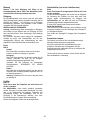
Additional Installation Specifications:
Use only the fixing screws supplied with the product for
installation or, if not supplied, purchase the correct screws
type.
Use the correct length for the screws which are identified in
the Installation Guide.
In case of doubt, consult an authorised service assistance
centre or similar qualified person.
WARNING! Failure to install the screws or fixing device in
accordance with these instructions may result in electrical
hazards.

15
Use
The hood is designed to be used either for exhausting or filter
version.
Ducting version
In this case the fumes are conveyed outside of the building by
means of a special pipe connected with the connection ring
located on top of the hood.
Attention! The exhausting pipe is not supplied and must be
purchased apart.
Diameter of the exhausting pipe must be equal to that of the
connection ring.
In the horizontal runs the exhausting pipe must be slightly
slanted (about 10°) and directed upwards to vent the air easily
from the room to the outside.
Attention! If the hood is supplied with active charcoal filter,
then it must be removed.
Connect the hood and discharge holes on the walls with a
diameter equivalent to the air outlet (connection flange).
Using the tubes and discharge holes on walls with smaller
dimensions will cause a diminution of the suction performance
and a drastic increase in noise.
Any responsibility in the matter is therefore declined.
! Use a duct of the minimum indispensible length.
! Use a duct with as few elbows as possible (maximum
elbow angle: 90°).
! Avoid drastic changes in the duct cross-section.
! Use a duct as smooth as possible inside.
! The duct must be made of certified material.
Filter version
One active charcoal filter is needed for this and can be
obtained from your usual retailer.
The filter removes the grease and smells from the extracted
air before sending it back into the room through the upper
outlet grid.
Installation
The minimum distance between the supporting surface for the
cooking equipment on the hob and the lowest part of the
range hood must be not less than 50cm from electric cookers
and 65cm from gas or mixed cookers.
If the instructions for installation for the gas hob specify a
greater distance, this must be adhered to.
Electrical connection
The mains power supply must correspond to the rating
indicated on the plate situated inside the hood. If provided with
a plug connect the hood to a socket in compliance with current
regulations and positioned in an accessible area, after
installation. If it not fitted with a plug (direct mains connection)
or if the plug is not located in an accessible area, after
installation, apply a double pole switch in accordance with
standards which assures the complete disconnection of the
mains under conditions relating to over-current category III, in
accordance with installation instructions.
Warning! Before re-connecting the hood circuit to the mains
supply and checking the efficient function, always check that
the mains cable is correctly assembled.
Warning! Power cable replacement must be undertaken by
the authorised service assistance centre or similar qualified
person.
Mounting
Before beginning installation:
• Check that the product purchased is of a suitable size for
the chosen installation area.
• Remove the charcoal (*) filter/s if supplied (see also
relative paragraph). This/these is/are to be mounted only
if you want lo use the hood in the filtering version.
• Check (for transport reasons) that there is no other
supplied material inside the hood (e.g. packets with
screws (*), guarantees (*), etc.), eventually removing
them and keeping them.
• If possible, disconnect and move freestanding or slide-in
range from cabinet opening to provide easier access to
rear wall/ceiling. Otherwise put a thick, protective
covering over countertop, cooktop or range to protect
from damage and debris. Select a flat surface for
assembling the unit. Cover that surface with a protective
covering and place all canopy hood parts and hardware
in it.
• In addition check whether near the installation area of the
hood (in the area accessible also with the hood mounted)
an electric socket is available and it is possible to
connect a fumes discharge device to the outside (only
suction version).
• Carry out all the masonry work necessary (e.g.
installation of an electric socket and/or a hole for the
passage of the discharge tube).
In the case of the presence of panels and/or walls and/or
lateral wall units check that there is sufficient space to install
the hood and that access to the command panel is easy.

16
Operation
Use the high suction speed in cases of concentrated kitchen
vapours. It is recommended that the cooker hood suction is
switched on for 5 minutes prior to cooking and to leave in
operation during cooking and for another 15 minutes
approximately after terminating cooking.
1 ON/OFF motor
Pressing the button, the hood turns on at speed 1.
Pressing the button during functioning, the hood turns
OFF.
2 Speed Increase
Pressing the button the hood passes from the OFF state
to speed 1.
Pressing the button (hood in ON state) the motor speed
is increased from speed 1 to intensive.
To each speed corresponds the ignition of the respective
led.
Speed 1 led L1
Speed 2 led L2
Speed 3 led L3
Intensive Speed led L4 (flashing)
The intensive speed is timed. The standard timing is 5’,
at the end of which the hood positions itself to speed 2.
To deactivate the function before the time expires press
key 2, the hood positions itself to speed 1, pressing key 1
the hood will turn off.
3 ON/OFF lights
4 Speed timing
5 Function state indicator
Speed Timing
The timing of the speed is enabled by pressing key 4, once
the timing expires the hood turns off.
The timing is subdivided as follows:
Speed 1 - 20 minutes (led L1 flashing)
Speed 2 - 15 minutes (led L2 flashing)
Speed 3 - 10 minutes (led L3 flashing)
Intensive Speed - 5 minutes (led L4 flashing)
During the timed functioning pressing key 1 the hood turns off,
if you press key 2 or key 4 the hood returns to the set speed.
Grease trap Signal
After 40 hours of operation the led L5 turns on.
When such signal appears the installed grease trap needs to
be washed.
To reset the signal hold down key 1 for 3”.
Carbon filter Signal
After 160 hours of operation the led L5 flashes.
When such signal appears the installed carbon filter must be
substituted.
To reset the signal hold down key 1 for 3”.
In the case of both filters signalling at the same time, the led
L5 will indicate the alarms alternately remaining on for 3" and
subsequently flashing 3 times.
The reset takes place by carrying out the procedure described
above 2 times.
The first time resets the grease trap signal, the second resets
the carbon filter signal.
In the standard mode the carbon filter signal is not active.
In case one uses the hood in filter version is it necessary to
enable the carbon filter signal.
Carbon filter signal activation:
Position the hood in OFF and simultaneously hold down keys
1 and 4 for 3”.
The led L1 and L2 will flash for 5”.
Carbon filter signal deactivation:
Position the hood in OFF and simultaneously hold down keys
1 and 4 for 3”.
The led L1 will flash for 2”.
Temperature Alarm
The hood is equipped with a temperature sensor that activates
the motor to speed 3 in the case that the temperature in the
control zone becomes too elevated.
The alarm condition is indicated with the sequential flash of
the leds L1, L2
, L3.
This condition remains until the temperature falls below the
alarm threshold.
You can get out of this mode by pressing key 1 or 2.
Every 30” the sensor checks the environmental temperature of
the display zone.

17
Maintenance
ATTENTION! Before performing any maintenance operation,
isolate the hood from the electrical supply by switching off at
the connector and removing the connector fuse.
Or if the appliance has been connected through a plug and
socket, then the plug must be removed from the socket.
Cleaning
The cooker hood should be cleaned regularly (at least with the
same frequency with which you carry out maintenance of the
fat filters) internally and externally. Clean using the cloth
dampened with neutral liquid detergent. Do not use abrasive
products. DO NOT USE ALCOHOL!
WARNING: Failure to carry out the basic cleaning
recommendations of the cooker hood and replacement of the
filters may cause fire risks.
Therefore, we recommend observing these instructions.
The manufacturer declines all responsibility for any damage to
the motor or any fire damage linked to inappropriate
maintenance or failure to observe the above safety
recommendations.
Panel
Fig. 10
Dismantling:
pull the panel out decisively and remove it from all the
connecting points.
Cleaning:
the panel should be cleaned with the same frequency as
the fat filters, using a cloth soaked in neutral liquid
detergents.
Avoid the use of products containing abrasives. DO NOT
USE ALCOHOL!
Montage:
The panel should be fixed between the pins placed for
this reason on the surface of the hood.
Attention! Always check that the panel is fixed in its
place well.
Grease filter
Fig. 8-11
Traps cooking grease particles.
The grease filter must be cleaned once a month using non
aggressive detergents, either by hand or in the dishwasher,
which must be set to a low temperature and a short cycle.
When washed in a dishwasher, the grease filter may discolour
slightly, but this does not affect its filtering capacity.
To remove the grease filter, pull the spring release handle.
Charcoal filter (filter version only)
Fig. 9
It absorbs unpleasant odours caused by cooking.
The saturation of the charcoal filter occurs after more or less
prolonged use, depending on the type of cooking and the
regularity of cleaning of the grease filter.
In any case it is necessary to replace the cartridge at least
every four mounths.
The charcoal filter may NOT be washed or regenerated.
Circular carbon filter
Apply one on each side as cover to both the shield grids of the
motor impeller, then turn clockwise.
For the disassembly, turn counter-clockwise.
Replacing lamps
The hood is equipped with a lighting system based on LED
technology.
The LEDs guarantee an optimum lighting, a duration up to 10
times as long as the traditional lamps and allow to save 90%
electrical energy.
For replacement, contact the technical service.

18
DE - Montage- und Gebrauchsanweisung
Die Instruktionen, die in diesem Handbuch gegeben werden,
müssen strikt eingehalten werden. Es wird keinerlei Haftung
übernommen für mögliche Mängel, Schäden oder Brände der
Dunstabzugshaube, die auf die Nichtbeachtung der Vorschriften in
diesem Handbuch zurückzuführen sind. Die Dunstabzugshaube
ist fuer die Absaugung der Kochduenste und Verbrennungsgase,
die waehrend des Kochvorgangs entstehen , entwickelt. Sie ist
nur zum Hausgebrauch geeignet.
Der Dunstabzugshaube kann von der aesthetischen Seite her
ander sein als die Zeichnungen die in diesem
Bedienungsanleitung geschrieben sind.
Die Bedienungsanleitungen , die Wartung und die Installation
sind aber gleich.
! Es ist wichtig diese Bedienungsanleitung zu behalten um sie
in jedem Moment nachzuschlagen. Im Fall von Verkaufen,
Abtretung oder Umziehen, versichern Sie sich bitte dass Sie
mit dem Produkt zusammen bleibt.
! Die Bedienungsanleitungen richtig lesen: es gibt wichtige
Informationen ueber die Installation, Benutzen und Sicherheit.
! Führen Sie keine elektrische oder mechanische
Aenderungen am Produkt oder an den Abgasrohren vor.
! Vor der Installation vergewissern Sie sich, dass das Gerät
keine Transportschäden aufweist. Bei auftretenden
Problemen setzen Sie sich bitte mit Ihrem Händler in
Verbindung.
Hinweis: Die mit dem (*) gekennzeichneten Teile sind
Zubehörteile, die nur bei einigen Modellen im Lieferumfang
enthalten sind oder Teile, die nicht im Lieferumfang enthalten sind,
und somit extra erworben werden müssen.
Warnung
Achtung! Das Gerät nicht an das Stromnetz anschließen, solange
die Installation noch nicht abgeschlossen ist.
Vor Beginn sämtlicher Reinigungs- oder Wartungsarbeiten muss
das Gerät durch Ziehen des Steckers oder Betätigen des
Hauptschalters der Wohnung vom Stromnetz getrennt werden.
Bei allen Installations- und Instandhaltungsarbeiten immer
Schutzhandschuhe tragen.
Kinder nicht mit dem Gerät spielen lassen.
Erwachsene und Kinder dürfen nie unbeaufsichtigt das Gerät
betreiben,
– wenn sie körperlich oder geistig dazu nicht in der Lage sind,
– oder wenn ihnen Wissen und Erfahrung fehlen, das Gerät richtig
und sicher zu bedienen.
Die Dunstabzugshaube niemals ohne korrekt montiertes Gitter in
Betrieb setzen!
Die Dunstabzugshaube darf NIEMALS als Abstellfläche verwendet
werden, sofern dies nicht ausdrücklich angegeben wird.
Der Raum muss über eine hinreichende Belüftung verfügen, wenn
die Dunstabzugshaube mit anderen gas- oder
brennstoffbetriebenen Geräten gleichzeitig verwendet wird.
Bei gleichzeitigem Betrieb der Dunstabzugshaube im Abluftbetrieb
und Feuerstätten darf im Aufstellraum der Feuerstätte der
Unterdruck nicht größer als 4 Pa (4 x 10
-5
bar) sein.
Die angesaugte Luft darf nicht in Rohre geleitet werden, die für die
Ableitung der Abgase von gas- oder brennstoffbetriebenen
Geräten genutzt werden.
Es ist strengstens verboten, unter der Haube mit offener Flamme
zu kochen.
Eine offene Flamme beschädigt die Filter und kann Brände
verursachen, daher ist dies in jedem Fall zu vermeiden.
Das Frittieren muss unter Aufsicht erfolgen, um zu vermeiden,
dass das überhitzte Öl Feuer fängt.
Zugängliche Teile können beim Gebrauch mit Kochgeräten heiss
werden.
In Bezug auf technische und Sicherheitsmaßnahmen für die
Ableitung der Abluft sind die Vorschriften der zuständigen örtlichen
Behörden strengstens einzuhalten.
Die Haube muss regelmäßig innen und außen gereinigt werden
(MINDESTENS EINMAL IM MONAT, diesbezüglich sind in jedem
Fall die ausdrücklichen Angaben in der Wartungsanleitung dieses
Handbuchs zu beachten).
Eine Nichtbeachtung der Vorschriften zur Reinigung der Haube
sowie zur Auswechselung und Reinigung der Filter führt zu
Brandgefahr.
Um das Risiko eines Stromschlages zu vermeiden, darf die
Dunstabzugshaube ohne richtig eingesetzte Lampen nicht
betrieben werden.
Es wird keinerlei Haftung übernommen für Fehler, Schäden oder
Brände des Gerätes, die durch Nichteinhaltung der in diesem
Handbuch aufgeführten Anweisungen verschuldet wurden.
In Übereinstimmung mit den Anforderungen der Europäischen
Richtlinie 2002/96/EG über Elektro- und Elektronik-Altgeräte
(WEEE) ist vorliegendes Gerät mit einer Kennzeichnung
versehen.
Sie leisten einen positiven Beitrag für den Schutz der Umwelt und
die Gesundheit des Menschen, wenn Sie dieses Gerät einer
gesonderten Abfallsammlung zuführen. Im unsortierten
Siedlungsmüll könnte ein solches Gerät durch unsachgemäße
Entsorgung negative Konsequenzen nach sich ziehen.
Auf dem Produkt oder der beiliegenden Produktdokumentation ist
folgendes Symbol
einer durchgestrichenen Abfalltonne
abgebildet. Es weist darauf hin, dass eine Entsorgung im normalen
Haushaltsabfall nicht zulässig ist. Entsorgen Sie dieses Produkt im
Recyclinghof mit einer getrennten Sammlung für Elektro- und
Elektronikgeräte. Die Entsorgung muss gemäß den örtlichen
Bestimmungen zur Abfallbeseitigung erfolgen.
Bitte wenden Sie sich an die zuständigen Behörden Ihrer
Gemeindeverwaltung, an den lokalen Recyclinghof für
Haushaltsmüll oder an den Händler, bei dem Sie dieses Gerät
erworben haben, um weitere Informationen über Behandlung,
Verwertung und Wiederverwendung dieses Produkts zu erhalten.

19
Betriebsart
Die Haube kann sowohl als Abluftgërat als auch als
Umluftgërat eingesetzt werden.
Abluftbetrieb
Die Luft wird mit Hilfe eines an den Abluftstutzen
anzubringenden Rohres ins Freie geleitet.
Das Abluftrohr wird hierbei nicht geliefert und soll separat
angekauft werden.
Das Abluftrohr muß denselben Durchmesser wie der
Abluftstutzen aufweisen.
Das Abluftrohr muß muß in waagrechter Lage leicht nach
oben geneigt sein (ca. 10%), damit die Luft ungehindert ins
Freie abgeleitet werden kann.
Note. Sollte die Dunstabzugshaube mit Aktiv-kohlefilter
versehen sein, so muß dieser entfernt werden.
Die Dunstabzugshaube an Abluftrohre und
Wandabluftauslass mit dem selben Durchmesser wie der
Luftausgang verbinden (Anschlussflansch).
Die Benutzung von Rohren und Wandabluftauslass mit
geringerem Durchmesser, verursacht eine Verringerung der
Abluftleistung und eine drastische Zunahme der
Geraeuschentwicklung.
Jegliche Verantwortung diesbezueglich wird daher abgelenkt
! Ein möglichst kurzes Rohr verwenden.
! Ein Rohrsystem mit einer möglichst geringen Anzahl von
Krümmungen verwenden (max. Winkel der Krümmung:
90°).
! Starke Änderungen des Rohrdurchmessers sind zu
vermeiden .
! Die Innenfläche der Rohrs muss so glatt wie möglich sein
.
! Verwenden Sie ausschließlich Rohre aus zugelassenen
Material.
Umluftbetrieb
Es ist ein Aktiv-Kohlefilter zu benutzen, der bei Ihrem
Fachhändler erhältlich ist.
Der Aktiv-Kohlefilter reinigt die angesaugte Luft von
Fettpartikeln und Kochdünsten bevor diese durch das obere
Gitter in die Küche zurückströmt.
Befestigung
Der Abstand zwischen der Abstellfläche auf dem Kochfeld und
der Unterseite der Dunstabzugshaube darf 50cm im Fall von
elektrischen Kochfeldern und 65cm im Fall von Gas- oder
kombinierten Herden nicht unterschreiten.
Wenn die Installationsanweisungen des Gaskochgeräts einen
größeren Abstand vorgeben, ist dieser zu berücksichtigen.
Elektrischer Anschluss
Die Netzspannung muss der Spannung entsprechen, die auf dem
Betriebsdatenschild im Innern der Haube angegeben ist. Sofern
die Haube einen Netzstecker hat, ist dieser an zugänglicher Stelle
an eine den geltenden Vorschriften entsprechende Steckdose
auch nach der Montage anzuschließen. Bei einer Haube ohne
Stecker (direkter Netzanschluss) oder falls der Stecker nicht
zugänglich ist, ist ein normgerechter zweipoliger Schalter auch
nach der Montage anzubringen, der unter Umständen der
Überspannung Kategorie III entsprechend den Installationsregeln
ein vollständiges Trennen vom Netz garantiert.
Hinweis! Vor der Inbetriebnahme muss sichergestellt sein , dass
die Netzversorgungleitung (Steckdose) ordnungsgemäß montiert
wurde.
Hinweis! Zur Vermeidung von Gefahren darf die Auswechselung
des Stromkabels nur vom autorisierten Kundendienst
vorgenommen werden.
Montage
Bevor Sie mit der Montage beginnen:
• Überprüfen Sie, dass das erstandene Produkt von der Größe
her dem Bereich entspricht, in dem es angebracht werden
soll.
• Entfernen Sie den/die Aktivkohlefilter (*), falls vorhanden
(siehe hierzu auch den entsprechenden Absatz "Wartung").
Der/die Aktivkohlefilter wird/werden nur wieder in die
Dunstabzugshaube eingesetzt, wenn diese im Umluftbetrieb
verwendet werden soll.
• Vergewissern Sie sich, dass sich im Inneren der
Dunstabzugshaube (aus Transportgründen) kein im
Lieferumfang enthaltenes Material (zum Beispiel Tütchen mit
Schrauben (*), die Garantie (*), usw.) befindet; falls
vorhanden, entfernen Sie dieses und heben Sie sie auf.
• Falls möglich, entfernen Sie die Möbel unter und um die
Dunstabzugshaube herum, um besseren Zugriff auf die
hintere Wand/Decke zu haben, wo die Haube angebracht
wird. Sonst legen Sie bitte eine Schutzabdeckung auf die
Kochplatte, Arbeitsfläche, sowie die Möbel und Wände, um
sie vor Schäden oder Schmutz zu schützen. Wählen Sie eine
ebene Oberfläche, um die Einheit zusammenzubauen.
Decken Sie diese Oberfläche mit einer Schutzfolie ab und
legen Sie die Dunstabzugshaube sowie alle im Lieferumfang
enthaltenen Teile darauf.
• Vergewissern Sie sich zudem, dass in der Nähe der Fläche,
an der die Dunstabzugshaube angebracht werden soll (eine
Fläche, die auch nach der Montage der Dunstabzugshaube
weiter zugänglich sein muss), eine Steckdose vorhanden ist
und es möglich ist, die Dunstabzugshaube an eine
Vorrichtung zum Ableiten der Dämpfe ins Freie
anzuschließen (nur Abluftbetrieb).
• Führen Sie alle notwendigen Arbeiten durch (z.B.: Einbau
einer Steckdose und/oder Anbringen eines Loches für den
Durchgang des Abluftrohres).
Im Fall von Abdeckungen und/oder Wänden und/oder seitlichen
Schränken vergewissern Sie sich bitte, dass genügend Raum
vorhanden ist, um die Dunstabzugshaube anzubringen und dass
Sie jederzeit Zugriff auf das Bedienfeld haben.

20
Betrieb
Bei starker Dampfentwicklung die höchste Betriebsstufe
einschalten. Es wird empfohlen, die Dunstabzugshaube schon
fünf Minuten vor Beginn des Kochvorganges einzuschalten
und sie nach dessen Beendigung noch ungefähr 15 Minuten
weiterlaufen zu lassen.
1 ON/OFF-Motor
Mit dieser Taste wird der Motor mit der 1.
Geschwindigkeitsstufe eingeschaltet.
Bei Betätigung dieser Taste bei laufendem Motor, wird
dieser AUSGESCHALTET.
2 Geschwindigkeitserhöhung
Bei Betätigung dieser Taste bei AUSGESCHALTETEM
Motor schaltet sich dieser in der 1. Geschwindigkeitsstufe
ein.
Bei Betätigung dieser Taste bei LAUFENDEM Motor wird
dieser von der 1. Geschwindigkeitsstufe zur Intensivstufe
umgeschaltet.
Jede Geschwindigkeitsstufe wird mit einer Led angezeigt.
Geschwindigkeitsstufe 1 Led L1
Geschwindigkeitsstufe 2 Led L2
Geschwindigkeitsstufe 3 Led L3
Intensivstufe Led L4 (blinkend)
Die Intensivstufe ist zeitabhängig: nach 5’ schaltet sich
der Motor auf die 2. Geschwindigkeitsstufe zurück.
Um diese Funktion vor Zeitablauf zu deaktivieren,
betätigen Sie die Taste 2: der Motor wird auf die 1.
Geschwindigkeitsstufe zurückgeschaltet. Bei Betätigung
der Taste 1 schaltet sich die Haube aus.
3 ON/OFF Beleuchtung
4 Timer der Geschwindigkeitsstufen
5 Anzeige des Funktionszustandes
Timer der Geschwindigkeitsstufen
Mit der Taste 4 kann der Betrieb der Haube für eine
bestimmte Zeit eingestellt werden. Nach abgelaufener Zeit
schaltet sich die Haube automatisch aus.
Der Timer regelt die Geschwindigkeitsstufen wie folgt vor:
Geschwindigkeitsstufe 1 - 20 Minuten (Led L1 blinkend)
Geschwindigkeitsstufe 2 - 15 Minuten (Led L2 blinkend)
Geschwindigkeitsstufe 3 - 10 Minuten (Led L3 blinkend)
Intensivstufe - 5 Minuten (Led L4 blinkend)
Wenn Sie bei eingeschaltetem Timer die Taste 1 betätigen,
wird die Haube abgeschaltet. Bei Betätigung der Taste 2 oder
der Taste 4 schaltet sich die Haube zur voreingestellten
Geschwindigkeitsstufe zurück.
Fettfilter Sättigungsanzeige
Nach 40 Betriebsstunden schaltet sich die LED ( L5 ) ein
(Dauerlicht), das bedeutet der Fettfilter muss gereinigt werden
.
Nach Reinigung und Einsatz der Fettfilter, drücken Sie die
Taste 1 und halten Sie diese für ca. 3 Sekunden gedrückt.
Nach ca. 3 Sekunden erlischt die LED ( L5 ) und damit wurde
der Reset erfolgreich durchgeführt.
Aktivkohlefilter-Sättigungsanzeige
Nach ca. 160 Betriebsstunden schaltet sich die LED ( L5 ) ein
(Blinklicht), das bedeutet der Kohlefilter muß ausgetauscht
werden.
Nach Austausch des Kohlefilters, drücken Sie die Taste 1und
halten Sie diese für ca. 3 Sekunden gedrückt.
Nach ca. 3 Sekunden erlischt die LED ( L5 ) und damit wurde
der Reset erfolgreich durchgeführt.
Sollten die Sättigungsanzeigen für beide Filter erscheinen,
wird Ihnen das durch ca. 3 Sekunden Dauerlicht und
anschließendem Blinken der LED (L5) im Wechsel angezeigt.
In diesem Fall bitte zunächst die Fettfilter- und anschließend
die Kohlefilterreinigung gemäß vorher genannter Anleitung
durchführen.
Bei Standard-Betriebsart ist die Aktivkohlefilter-
Sättigungsanzeige nicht aktiv.
Bei Hauben mit Umluftbetrieb muss die Aktivkohlefilter-
Sättigungsanzeige aktiviert werden.
Aktivierung der Aktivkohlefilter-Sättigungsanzeige:
Stellen Sie den Hauptschalter in die AUS-Position und halten
Sie die Tasten 1 und 4 3 Sekunden gleichzeitig gedrückt.
Die Leds L1 und L2 blinken für 5 Sekunden.
Deaktivierung der Aktivkohlefilter-Sättigungsanzeige:
Stellen Sie den Hauptschalter in die AUS-Position und die
Tasten 1 und 4 3 Sekunden gleichzeitig gedrückt halten.
Die Led L1 blinkt für 2 Sekunden.
Temperaturanzeige
Die Haube ist mit einem Temperatursensor ausgerüstet, der
den Motor auf die 3. Geschwindigkeitsstufe zurückschalten
lässt, wenn die Temperatur im Bedienfeld-Bereich zu hoch
wird.
Der Alarmzustand wird durch das zyklische Blinken der Leds
L1,
L2, L3 angezeigt.
Der Alarmzustand wird erst beendet, wenn die Temperatur
unterhalb des Alarmwertes wieder liegt.
Diese Funktion kann beendet werden, indem Sie die Taste 1
oder 2 betätigen.
Der Temperatursensor stellt die Raumtemperatur im Display-
Bereich alle 30 Sekunden fest.
Pagina se încarcă...
Pagina se încarcă...
Pagina se încarcă...
Pagina se încarcă...
Pagina se încarcă...
Pagina se încarcă...
Pagina se încarcă...
Pagina se încarcă...
Pagina se încarcă...
Pagina se încarcă...
Pagina se încarcă...
Pagina se încarcă...
Pagina se încarcă...
Pagina se încarcă...
Pagina se încarcă...
Pagina se încarcă...
Pagina se încarcă...
Pagina se încarcă...
Pagina se încarcă...
Pagina se încarcă...
Pagina se încarcă...
Pagina se încarcă...
Pagina se încarcă...
Pagina se încarcă...
Pagina se încarcă...
Pagina se încarcă...
Pagina se încarcă...
Pagina se încarcă...
Pagina se încarcă...
Pagina se încarcă...
Pagina se încarcă...
Pagina se încarcă...
Pagina se încarcă...
Pagina se încarcă...
Pagina se încarcă...
Pagina se încarcă...
Pagina se încarcă...
Pagina se încarcă...
Pagina se încarcă...
Pagina se încarcă...
Pagina se încarcă...
Pagina se încarcă...
Pagina se încarcă...
Pagina se încarcă...
Pagina se încarcă...
Pagina se încarcă...
Pagina se încarcă...
Pagina se încarcă...
Pagina se încarcă...
Pagina se încarcă...
Pagina se încarcă...
Pagina se încarcă...
Pagina se încarcă...
Pagina se încarcă...
Pagina se încarcă...
Pagina se încarcă...
Pagina se încarcă...
Pagina se încarcă...
Pagina se încarcă...
Pagina se încarcă...
Pagina se încarcă...
Pagina se încarcă...
Pagina se încarcă...
Pagina se încarcă...
Pagina se încarcă...
Pagina se încarcă...
Pagina se încarcă...
Pagina se încarcă...
Pagina se încarcă...
Pagina se încarcă...
Pagina se încarcă...
Pagina se încarcă...
Pagina se încarcă...
Pagina se încarcă...
Pagina se încarcă...
Pagina se încarcă...
Pagina se încarcă...
Pagina se încarcă...
Pagina se încarcă...
Pagina se încarcă...
Pagina se încarcă...
Pagina se încarcă...
Pagina se încarcă...
Pagina se încarcă...
Pagina se încarcă...
Pagina se încarcă...
Pagina se încarcă...
Pagina se încarcă...
Pagina se încarcă...
Pagina se încarcă...
Pagina se încarcă...
Pagina se încarcă...
Pagina se încarcă...
Pagina se încarcă...
Pagina se încarcă...
Pagina se încarcă...
Pagina se încarcă...
Pagina se încarcă...
Pagina se încarcă...
Pagina se încarcă...
Pagina se încarcă...
Pagina se încarcă...
-
 1
1
-
 2
2
-
 3
3
-
 4
4
-
 5
5
-
 6
6
-
 7
7
-
 8
8
-
 9
9
-
 10
10
-
 11
11
-
 12
12
-
 13
13
-
 14
14
-
 15
15
-
 16
16
-
 17
17
-
 18
18
-
 19
19
-
 20
20
-
 21
21
-
 22
22
-
 23
23
-
 24
24
-
 25
25
-
 26
26
-
 27
27
-
 28
28
-
 29
29
-
 30
30
-
 31
31
-
 32
32
-
 33
33
-
 34
34
-
 35
35
-
 36
36
-
 37
37
-
 38
38
-
 39
39
-
 40
40
-
 41
41
-
 42
42
-
 43
43
-
 44
44
-
 45
45
-
 46
46
-
 47
47
-
 48
48
-
 49
49
-
 50
50
-
 51
51
-
 52
52
-
 53
53
-
 54
54
-
 55
55
-
 56
56
-
 57
57
-
 58
58
-
 59
59
-
 60
60
-
 61
61
-
 62
62
-
 63
63
-
 64
64
-
 65
65
-
 66
66
-
 67
67
-
 68
68
-
 69
69
-
 70
70
-
 71
71
-
 72
72
-
 73
73
-
 74
74
-
 75
75
-
 76
76
-
 77
77
-
 78
78
-
 79
79
-
 80
80
-
 81
81
-
 82
82
-
 83
83
-
 84
84
-
 85
85
-
 86
86
-
 87
87
-
 88
88
-
 89
89
-
 90
90
-
 91
91
-
 92
92
-
 93
93
-
 94
94
-
 95
95
-
 96
96
-
 97
97
-
 98
98
-
 99
99
-
 100
100
-
 101
101
-
 102
102
-
 103
103
-
 104
104
-
 105
105
-
 106
106
-
 107
107
-
 108
108
-
 109
109
-
 110
110
-
 111
111
-
 112
112
-
 113
113
-
 114
114
-
 115
115
-
 116
116
-
 117
117
-
 118
118
-
 119
119
-
 120
120
-
 121
121
-
 122
122


ELICA Hidden Ix/A/90 Manual de utilizare
- Categorie
- Hote pentru aragaz
- Tip
- Manual de utilizare
în alte limbi
- slovenčina: ELICA Hidden Ix/A/90 Používateľská príručka
Lucrări înrudite
-
ELICA MOON IX/F/60 Manual de utilizare
-
-
-
-
-
-
-
-
-