
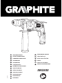
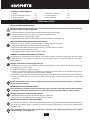
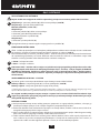
MŁOTOWIERTARKA
ROTARY HAMMER DRILL
HAMMERBOHRMASCHINE
ПЕРФОРАТОР
ПЕРФОРАТОР
FÚRÓKALAPÁCS
BORMASINA PERCUTANTA
VRTACÍ KLADIVO
VŔTACIE KLADIVO
VRTALNO KLADIVO
PERFORATORIUS
PERFORATORS
LÖÖKTRELL
G.0616
58G505
БОРМАШИНА УДАРНА
ČEKIĆ-BUŠILICA
BUŠILICA SA ČEKIĆEM
ΣΦΥΡΑ
ES MARTILLO-TALADRO
MARTELLO PERFORATORE
1


INSTRUKCJA OBSŁUGI . . . . . . . . . . . . . . . . . . 5
INSTRUCTION MANUAL . . . . . . . . . . . . . . . . 12
BETRIEBSANLEITUNG. . . . . . . . . . . . . . . . . . 16
РУКОВОДСТВО ПО ЭКСПЛУАТАЦИИ . . . . . . . 21
ІНСТРУКЦІЯ З ЕКСПЛУАТАЦІЇ . . . . . . . . . . . . 26
HASZNÁLATI UTASÍTÁS. . . . . . . . . . . . . . . . . 31
INSTRUCTIUNI DE DESERVIRE . . . . . . . . . . . . 36
INSTRUKCE K OBSLUZE. . . . . . . . . . . . . . . . . 41
NÁVOD NA OBSLUHU . . . . . . . . . . . . . . . . . . 46
NAVODILA ZA UPORABO . . . . . . . . . . . . . . . 51
APTARNAVIMO INSTRUKCIJA. . . . . . . . . . . . . 56
LIETOŠANAS INSTRUKCIJA . . . . . . . . . . . . . . 61
KASUTUSJUHEND . . . . . . . . . . . . . . . . . . . . 66
ИНСТРУКЦИЯ ЗА ОБСЛУЖВАНЕ . . . . . . . . . . 71
UPUTE ZA UPOTREBU. . . . . . . . . . . . . . . . . . 76
UPUTSTVO ZA UPOTREBU . . . . . . . . . . . . . . 81
ΟΔΗΓΙΕΣ ΧΡΗΣΗΣ . . . . . . . . . . . . . . . . . . . . 86
INSTRUCCIONES DE USO. . . . . . . . . . . . . . . . 91
MANUALE PER L’USO . . . . . . . . . . . . . . . . . . 96
ES

4
2
1
A
2
1
D
C
5
B8
3
4
PRESS
1
2
7
6
5
8
4
3

5
INSTRUKCJA ORYGINALNA (OBSŁUGI)
MŁOTOWIERTARKA
58G505
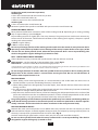
UWAGA: PRZED PRZYSTĄPIENIEM DO UŻYTKOWANIA ELEKTRONARZĘDZIA NALEŻY UWAŻNIE PRZECZYTAĆ
NINIEJSZĄ INSTRUKCJĘ I ZACHOWAĆ JĄ DO DALSZEGO WYKORZYSTANIA.
SZCZEGÓŁOWE PRZEPISY BEZPIECZEŃSTWA
ƔZakładać środki ochrony słuchu podczas pracy młotowiertarką. Narażenie się na hałas może spowo-
dować utratę słuchu.
ƔZakładać środki ochrony dróg oddechowych podczas pracy młotowiertarką. Narażenie się na pył
może spowodować choroby układu oddechowego.
ƔJeśli wymaga tego charakter wykonywanej pracy należy stosować systemy odpylające.
ƔNarzędzie używać z dodatkowymi rękojeściami dostarczonymi z narzędziem. Utrata kontroli może
spowodować osobiste obrażenia operatora.
UWAGA! Urządzenie służy do pracy wewnątrz pomieszczeń.
Mimo zastosowania konstrukcji bezpiecznej z samego założenia, stosowania środków zabezpiecza-
jących i dodatkowych środków ochronnych, zawsze istnieje ryzyko szczątkowe doznania urazów
podczas pracy.
BUDOWA I PRZEZNACZENIE
Młotowiertarka jest ręcznym elektronarzędziem z izolacją II klasy. Urządzenie jest napędzane jednofazo-
wym silnikiem komutatorowym, którego prędkość obrotowa jest redukowana za pośrednictwem przekład-
ni zębatej. Młotowiertarka może być używana do wiercenia otworów w trybie pracy z udarem lub bez uda-
ru. Obszary ich użytkowania to wykonawstwo prac remontowo - budowlanych, stolarskich oraz wszelkich
prac z zakresu samodzielnej działalności amatorskiej (majsterkowanie).
Nie wolno używać elektronarzędzia niezgodnie z jego przeznaczeniem
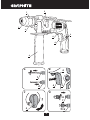
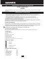
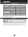
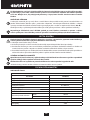
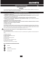
OPIS STRON GRAFICZNYCH
Poniższa numeracja odnosi się do elementów urządzenia przedstawionych na stronach gracznych niniej-
szej instrukcji.
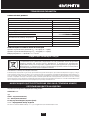
1. Uchwyt SDS-PLUS
2. Tuleja mocująca
3. Przycisk blokady włącznika
4. Włącznik
5. Przełącznik trybu pracy
6. Rękojeść dodatkowa
7. Listwa ogranicznika głębokości wiercenia
8. Przełącznik kierunku obrotów
* Mogą występować różnice między rysunkiem a wyrobem
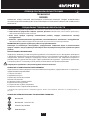
OPIS UŻYTYCH ZNAKÓW GRAFICZNYCH
UWAGA
OSTRZEŻENIE
MONTAŻ/USTAWIENIA
INFORMACJA

6
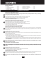
WYPOSAŻENIE I AKCESORIA
1. Wiertła - 1 szt
2. Listwa ogranicznika głębokości - 1 szt
3. Rękojeść dodatkowa - 1 szt
4. Uchwyt wiertarski + kluczyk - 1 szt
5. Adapter do uchwytu - 1 szt
6. Zasobnik ze smarem - 1 szt
7. Walizka transportowa - 1 szt
PRZYGOTOWANIE DO PRACY
INSTALOWANIE RĘKOJEŚCI DODATKOWEJ
Ze względów bezpieczeństwa przy posługiwaniu się młotowiertarką zawsze należy stosować ręko-
jeść dodatkową (6), która może być zamocowana w dowolnym położeniu.
ƔPoluzować pokrętło blokujące kołnierz rękojeści (6), pokręcając je w lewo.
ƔNasunąć kołnierz rękojeści na walcową część obudowy młotowiertarki.
ƔObrócić do najbardziej dogodnego położenia.
ƔDokręcić pokrętło blokujące w prawo celem zamocowania rękojeści.
INSTALOWANIE LISTWY OGRANICZNIKA GŁĘBOKOŚCI WIERCENIA
Ogranicznik (7) służy do ustalenia głębokości zagłębienia wiertła w materiał.
ƔPoluzować pokrętło blokujące kołnierz rękojeści dodatkowej (6).
ƔWsunąć listwę ogranicznika (7) w otwór w kołnierzu rękojeści dodatkowej.
ƔUstawić pożądaną głębokość wiercenia.
ƔZablokować, poprzez dokręcenie pokrętła blokującego.
MONTAŻ I WYMIANA NARZĘDZI ROBOCZYCH
Młotowiertarka jest przystosowana do pracy z narzędziami roboczymi posiadającymi chwyty typu
SDS-PLUS. Przed rozpoczęciem pracy oczyścić młotowiertarkę i narzędzia robocze. Wykorzystując smar na-
łożyć cienką warstwę na trzpień narzędzia roboczego.
Odłączyć elektronarzędzie od zasilania.
Młotowiertarka posiada system mocowania clic-clic (bez konieczności odciągania tulei mocującej (2) pod-
czas montażu narzędzia roboczego).
ƔOprzeć młotowiertarkę na stabilnej powierzchni.
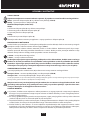
ƔWłożyć trzpień narzędzia roboczego do uchwytu (1), wsuwając go do oporu (może zajść potrzeba obró-
cenia narzędzia roboczego, aż zajmie ono właściwe położenie) (rys. A).
ƔNarzędzie robocze jest właściwie osadzone, jeśli nie daje się wyjąć bez odciągnięcia tulei mocującej
uchwytu.
ƔJeśli tuleja (2) nie wraca w pełni do położenia pierwotnego, należy wyjąć narzędzie robocze i całą ope-
rację powtórzyć.
Wysoką sprawność pracy młotowiertarką uzyskuje się tylko wtedy, jeśli stosowane są ostre i nieusz-
kodzone narzędzia robocze.
DEMONTAŻ NARZĘDZIA ROBOCZEGO
Tuż po zakończeniu pracy narzędzia robocze mogą być gorące. Należy unikać kontaktu bezpośred-
niego z nimi i stosować odpowiednie rękawice ochronne. Narzędzia robocze po wyjęciu należy oczy-
ścić.
Odłączyć elektronarzędzie od zasilania.
ƔOdciągnąć do tyłu i przytrzymać tuleję mocującą (2).
ƔDrugą ręką wyciągnąć narzędzie robocze do przodu.
SPRZĘGŁO PRZECIĄŻENIOWE
Młotowiertarka jest wyposażona w wewnętrznie ustawione sprzęgło przeciążeniowe. Wrzeciono młoto-
wiertarki zatrzymuje się, gdy tylko narzędzie robocze zakleszcza się, co mogłoby spowodować przeciążenie
elektronarzędzia.

7
Zawsze należy stosować okulary lub gogle przeciwodpryskowe szczególnie, gdy wiercony jest otwór
nad głową operatora.
PRACA / USTAWIENIA
WŁĄCZANIE / WYŁĄCZANIE
Napięcie sieci musi odpowiadać wielkości napięcia podanego na tabliczce znamionowej młotowiertarki.
Włączenie - wcisnąć przycisk włącznika (4) i przytrzymać w tej pozycji (rys B).
Wyłączenie - zwolnić nacisk na przycisk włącznika (4)
Blokada włącznika (praca ciągła)
Włączanie:
ƔWcisnąć przycisk włącznika (4) i przytrzymać w tej pozycji.
ƔWcisnąć przycisk blokady włącznika (3).
ƔZwolnić nacisk na przycisk włącznika (4).
Wyłączanie:
ƔWcisnąć i puścić przycisk włącznika (4).
Zakres prędkości obrotowej wrzeciona regulowany jest stopniem nacisku na przycisk włącznika (4).
PRZEŁĄCZNIK TRYBU PRACY
Młotowiertarka jest wyposażona w 2 funkcyjny przełącznik trybu pracy (5). W zależności od ustawienia
można wykonywać wiercenie bez udaru lub wiercenie z udarem (rys C).
Wiercenie z udarem wymaga niewielkiego docisku młotowiertarki. Nadmierny docisk niepotrzebnie spo-
wodowałby działanie zbyt dużego obciążenia na silnik. Regularnie trzeba kontrolować stan techniczny na-
rzędzi roboczych. W razie potrzeby narzędzia robocze trzeba naostrzyć lub wymienić.
ƔPoz 0 = wiercenie bez udaru ( symbol wiertła)
ƔPoz 1 = wiercenie z udarem ( symbol wiertła i młotka)
Nie wolno podejmować próby zmiany położenia przełącznika trybu pracy w czasie, gdy pracuje sil-
nik młotowiertarki. Takie postępowanie mogłoby doprowadzić do poważnego uszkodzenia młoto-
wiertarki, a nawet do zranienia użytkownika. Nie wolno posługiwać się trójszczękowym uchwytem
wiertarskim, gdy młotowiertarka jest ustawiona na pracę w trybie wiercenia z udarem. Ten uchwyt
jest przeznaczony wyłącznie do wiercenia bez udaru (w drewnie lub stali).
KIERUNEK OBRÓTÓW W PRAWO W LEWO
Za pomocą przełącznika obrotów (8) dokonuje wyboru kierunku obrotów wrzeciona młotowiertarki.
Obroty w prawo – ustawić przełącznik (8) w osi włącznika (rys B).
Obroty w lewo – ustawić przełącznik (8) w skrajnym prawym położeniu.
* Zastrzega się, że w niektórych przypadkach położenie przełącznika w stosunku do obrotów może być inne niż opisano.
Należy odnieść się do znaków gracznych umieszczonych na przełączniku lub obudowie urządzenia.
Nie wolno dokonywać zmiany kierunku obrotów w czasie, gdy wrzeciono młotowiertarki obraca się.
Przed uruchomieniem sprawdzić czy przełącznik kierunku obrotów jest we właściwym położeniu.
Nie powinno się używać lewego kierunku obrotów przy włączonym udarze.
WIERCENIE OTWORÓW
ƔPrzystępując do pracy z zamiarem wykonania otworu o dużej średnicy zaleca się rozpoczynać od wy-
wiercenia otworu mniejszego, a później rozwiercenia go na pożądany wymiar. Zapobiegnie to możliwo-
ści przeciążenia młotowiertarki.
ƔPrzy wykonywaniu głębokich otworów należy wiercić stopniowo na mniejsze głębokości, wycofywać
wiertło z otworu, aby umożliwić usunięcie wiórów lub pyłu z otworu.
ƔJeśli dojdzie do zakleszczenia się wiertła w czasie wiercenia zadziała sprzęgło przeciążeniowe. Należy
natychmiast wyłączyć młotowiertarkę, aby nie dopuścić do jej uszkodzenia. Usunąć zakleszczone wiertło
z otworu.

8
ƔNależy utrzymywać młotowiertarkę w osi wykonywanego otworu. Najbardziej efektywną pracę zapewni
ustawienie wiertła pod kątem prostym do powierzchni obrabianego materiału. W przypadku nie zacho-
wania prostopadłości w czasie pracy, może dojść do zakleszczenia lub złamania się wiertła w otworze, a
tym samym do zranienia użytkownika.
Wiercenie długotrwałe przy niskiej prędkości obrotowej wrzeciona grozi przegrzaniem silnika. Na-
leży robić okresowe przerwy w pracy lub zezwolić, aby urządzenie popracowało na maksymalnych
obrotach bez obciążenia przez okres około 3 min. Uważać, aby nie przesłonić otworów w obudowie
służących do wentylacji silnika młotowiertarki.
WIERCENIE BEZ UDARU
Takie materiały jak stal, drewno i tworzywa sztuczne mogą być wiercone za pomocą młotowiertarki po-
przez użycie trójszczękowego uchwytu wraz z adapterem przejściowym. Zmontować poprzez skręcenie
uchwyt trójszczękowy i adapter, a następnie umieścić w uchwycie młotowiertarki ( postępować jak w przy-
padku wierteł z chwytem SDS-PLUS) (rys D).
Należy używać wierteł ze stali szybkotnących lub ze stali węglowych (tylko w drewnie i materiałach drew-
nopodobnych).
Nie wolno posługiwać się trójszczękowym uchwytem wiertarskim, gdy młotowiertarka jest ustawio-
na na pracę w trybie wiercenia z udarem. Ten uchwyt jest przeznaczony wyłącznie do wiercenia bez
udaru (w drewnie lub stali).
OBSŁUGA I KONSERWACJA
Przed przystąpieniem do jakichkolwiek czynności związanych z instalowaniem, regulacją, naprawą
lub obsługą należy wyjąć wtyczkę przewodu zasilającego z gniazdka sieciowego.
ƔMłotowiertarkę należy utrzymywać zawsze w stanie czystym.
ƔDo czyszczenia plastikowych elementów młotowiertarki nigdy nie wolno stosować jakichkolwiek środ-
ków żrących.
ƔPo zakończeniu pracy, w celu usunięcia nalotu pyłu, należy młotowiertarkę przedmuchać za pomocą stru-
mienia sprężonego powietrza, szczególnie w celu udrożnienia szczelin wentylacyjnych obudowy silnika.
ƔRegularnie trzeba kontrolować stan szczotek węglowych silnika elektrycznego (zabrudzone lub zużyte
nadmiernie szczotki mogą spowodować nadmierne iskrzenie i spadek prędkości obrotowej wrzeciona
młotowiertarki).
WYMIANA SZCZOTEK WĘGLOWYCH
Zużyte (krótsze niż 5 mm), spalone lub pęknięte szczotki węglowe silnika należy natychmiast wy-
mienić. Zawsze dokonuje się jednocześnie wymiany obu szczotek. Czynność wymiany szczotek wę-
glowych należy powierzyć wyłącznie osobie wykwalikowanej wykorzystując części oryginalne.
Wszelkiego rodzaju usterki powinny być usuwane przez autoryzowany serwis producenta

9
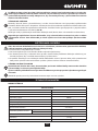
PARAMETRY TECHNICZNE
DANE ZNAMIONOWE
Młotowiertarka
Parametr Wartość
Napięcie zasilania 230 V AC
Częstotliwość zasilania 50 Hz
Moc znamionowa 400 W
Prędkość obrotowa bez obciążenia 0-1500 min-1
Częstotliwość udaru 0-6600 min-1
Energia udaru 1,5 J
Uchwyt SDS-PLUS
Maksymalna średnica wiercenia beton 10 mm
stal 13 mm
Klasa ochronności II
Masa 1,75 kg
Rok produkcji 2016
DANE DOTYCZĄCE HAŁASU I DRGAŃ
Poziom ciśnienia akustycznego LpA = 87,5 dB(A) K=3 dB(A)
Poziom mocy akustycznej LwA = 98,5 dB(A) K=3 dB(A)
Wartość przyspieszenia drgań ah = 10,768 m/s2 K=1,5 m/s2
OCHRONA ŚRODOWISKA / CE
Produktów zasilanych elektrycznie nie należy wyrzucać wraz z domowymi odpadkami, lecz oddać
je do utylizacji w odpowiednich zakładach. Informacji na temat utylizacji udzieli sprzedawca pro-
duktu lub miejscowe władze. Zużyty sprzęt elektryczny i elektroniczny zawiera substancje nieobo-
jętne dla środowiska naturalnego. Sprzęt nie poddany recyclingowi stanowi potencjalne zagrożenie
dla środowiska i zdrowia ludzi.
* Zastrzega się prawo dokonywania zmian.
„Grupa Topex Spółka z ograniczoną odpowiedzialnością” Spółka komandytowa z siedzibą w Warszawie, ul. Pograniczna 2/4 (dalej: „Grupa To-
pex”) informuje, iż wszelkie prawa autorskie do treści niniejszej instrukcji (dalej: „Instrukcja”), w tym m.in. jej tekstu, zamieszczonych fotograi,
schematów, rysunków, a także jej kompozycji, należą wyłącznie do Grupy Topex i podlegają ochronie prawnej zgodnie z ustawą z dnia 4 lutego
1994 roku, o prawie autorskim i prawach pokrewnych (tj. Dz. U. 2006 Nr 90 Poz 631 z późn. zm.). Kopiowanie, przetwarzanie, publikowanie,
modykowanie w celach komercyjnych całości Instrukcji jak i poszczególnych jej elementów, bez zgody Grupy Topex wyrażonej na piśmie, jest
surowo zabronione i może spowodować pociągnięcie do odpowiedzialności cywilnej i karnej.

10
Deklaracja Zgodności WE
/Declaration of Conformity/
/Megfelelési Nyilatkozat (EK)/
Producent
/Manufacturer/
/Gyártó/
Grupa Topex Sp. z o.o. Sp. k.
Ul. Pograniczna 2/4, 02-285 Warszawa, Polska
Wyrób
/Product/
/Termék/
Młotowiertarka
/Rotary hammer drill/
/Fúrókalapács/
Model
/Model./
/Modell/
58G505
Numer seryjny
/Serial number/
/Sorszám/
00001 ÷ 99999
Opisany wyżej wyrób jest zgodny z następującymi dokumentami:
/The above listed product is in conformity with the following UE Directives:/
/A fent jelzett termék megfelel az alábbi irányelveknek:/
Dyrektywa Maszynowa 2006/42/WE
/Machinery Directive 2006/42/EC/
/ 2006/42/EK Gépek /
Dyrektywa o Kompatybilności Elektromagnetycznej 2014/30/EU
/EMC Directive 2014/30/EU/
/2014/30/EK Elektromágneses összeférhetőség/
Dyrektywa o RoHS 2011/65/UE
/RoHS Directive 2011/65/UE/
2011/65/EK RoHS
oraz spełnia wymagania norm:
/and fulls requirements of the following Standards:/
/valamint megfelel az alábbi szabványoknak:/
EN 60745-1:2009+A11:2010; EN 60745-2-6:2010; EN 55014-1:2006+A1:2009+A2:2011;
EN 55014-2:1997+A1:2001+A2:2008; EN 61000-3-2:2014; EN 61000-3-3:2013; EN 50581:2012
Ostatnie dwie cyfry roku, w którym umieszczono znak CE: 12
/Last two gures of CE marking year:/
/A CE jelzés felhelyezése évének utolsó két számjegye:/
Nazwisko i adres osoby mającej miejsce zamieszkania lub siedzibę w UE upoważnionej do przygotowania dokumentacji
technicznej
/Name and address of the person who established in the Community and authorized to compile the technical le/
/A műszaki dokumentáció összeállítására felhatalmazott, a közösség területén lakóhellyel vagy székhellyel rendelkező személy
neve és címe./
Paweł Szopa
ul. Pograniczna 2/4
02-285 Warszawa
Paweł Szopa
Pełnomocnik ds. jakości rmy GRUPA TOPEX
/GRUPA TOPEX Quality Agent /
/A GRUPA TOPEX Minőségügyi meghatalmazott képviselője/
Warszawa, 2016-06-06

11
GWARANCJA I SERWIS
Warunki gwarancji oraz opis postepowania w przypadku reklamacji zawarte są w załączonej Karcie
Gwarancyjnej.
Serwis Centralny
GTX Service tel. +48 22 573 03 85
Ul. Pograniczna 2/4 fax. +48 22 573 03 83
02-285 Warszawa e-mail [email protected]
Sieć Punktów Serwisowych do napraw gwarancyjnych i pogwarancyjnych dostępna na platformie
internetowej gtxservice.pl
GRAPHITE zapewnia dostępność części zamiennych oraz materiałów eksploatacyjnych dla urządzeń
i elektronarzędzi. Pełna oferta części i usług na gtxservice.pl.
Zeskanuj QR kod i wejdź na gtxservice.pl

12
TRANSLATION OF THE ORIGINAL INSTRUCTIONS
ROTARY HAMMER DRILL
58G505
CAUTION: BEFORE USING THE POWER TOOL READ THIS MANUAL CAREFULLY AND KEEP IT FOR FUTURE
REFERENCE.
DETAILED SAFETY REGULATIONS
ƔUse ear protection when operating the rotary hammer drill. Noise hazards may cause hearing loss.
ƔUse protection measures for respiratory system when operating the rotary hammer drill. Dust ha-
zards may cause respiratory system illness.
ƔUse dust extraction systems whenever required by the nature of the work performed.
ƔUse additional handles supplied with the tool. Loss of control may cause operator personal injury.
CAUTION! This device is designed to operate indoors.
The design is assumed to be safe, protection measures and additional safety systems are used, ne-
vertheless there is always a small risk of operational injuries.
CONSTRUCTION AND USE
Rotary hammer is a hand-operated power tool with insulation class II. The tool is driven by single-phase
commutator motor with rotational speed reduced with gear transmission. Rotary hammer can be used for
drilling holes in working modes with impact or rotation only. Range of use covers repair and building works,
woodworking and any work from the scope of individual, amateur activities (tinkering).
Use the power tool according to the manufacturer’s instructions only.
DESCRIPTION OF DRAWING PAGES
Below enumeration refers to the device elements depicted on the drawing pages of this manual.
1. SDS-PLUS chuck
2. Fixing sleeve
3. Switch lock button
4. Switch
5. Operation mode switch
6. Additional handle
7. Depth gauge rod
8. Direction selector switch
* Dierences may appear between the product and drawing
MEANING OF SYMBOLS
CAUTION
WARNING
ASSEMBLY/SETTINGS
INFORMATION
EQUIPMENT AND ACCESSORIES
1. Drills - 1 pce
2. Depth gauge rod - 1 pce
3. Additional handle - 1 pce
4. Drill chuck + key - 1 pce
5. Chuck adapter - 1 pce
6. Grease container - 1 pce
7. Transport case - 1 pce

13
INSTALLATION OF ADDITIONAL HANDLE
Due to safety issues, always use additional handle (6) when operating the rotary hammer drill. It can
be xed in any position.
ƔTurn left the wheel lock that locks handle collar (6) to loosen it.
ƔSlide the handle collar over cylindrical part of the rotary hammer drill body.
ƔTurn for the most comfortable position.
ƔTurn the wheel lock tight to the right to clamp the handle.
INSTALLATION OF DEPTH GAUGE ROD
Depth gauge rod (7) serves to limit the depth of drill penetration of material.
ƔLoosen the wheel lock, which blocks collar of the additional handle (6).
ƔSlide depth gauge rod (7) into the hole in the additional handle collar.
ƔSet desired drilling depth.
ƔFix by tightening the wheel lock.
INSTALLATION AND REPLACEMENT OF WORKING TOOLS
Rotary hammer drill is designed to operate with working tools with SDS-PLUS shanks. Prior to operation
clean the rotary hammer drill and working tools. Use lubricant and apply thin layer onto shank of the work-
ing tool.
Disconnect the power tool from power supply.
Rotary hammer drill features clic-clic system (which does not require to pull o the xing sleeve (2) when
installing a working tool).
ƔPut the rotary hammer against stable surface.
ƔInsert working tool shank into chuck (1) and slide it to mechanical stop (it may be necessary to turn the
working tool so it can reach appropriate position) (g. A).
ƔWorking tool is properly seated if it cannot be removed without pulling o the xing sleeve.
ƔIf the sleeve (2) does not return to its default position, remove the working tool and repeat the whole
operation.
High eciency of the rotary hammer drill operation can be achieved by using sharp and undamaged
working tools.
DEINSTALLATION OF WORKING TOOL
Just after the operation is nished, the working tool may be hot. Avoid direct contact and use appro-
priate protective gloves. Clean the working tool after removal.
Disconnect the power tool from power supply.
ƔPull the xing sleeve (2) to the back and hold.
ƔRemove the working tool with your second hand by pulling it to the front.
OVERLOAD CLUTCH
Rotary hammer drill features overload clutch with factory setting. Spindle of the rotary hammer stops im-
mediately after working tool jams, what might overload the power tool.
Always use glasses or anti-splinter goggles, especially when drilling a hole above your head.
OPERATION / SETTINGS
SWITCHING ON / SWITCHING OFF
The mains voltage must match the voltage on the rating plate of the rotary hammer drill.
Switching on – press the switch button (4) and hold in this position (g. B).
Switching o – release pressure on the switch (4).

14
Locking the switch (continuous operation)
Switching on:
ƔPress the switch button (4) and hold in this position.
ƔPress the switch lock button (3).
ƔRelease pressure on the switch button (4).
Switching o:
ƔPress and release the switch button (4).
Rotational speed of the spindle is controlled with pressure on the switch button (4).
OPERATION MODE SWITCH
Rotary hammer drill features 2-function switch of the working mode (5). Depending on its setting, a drilling
only or impact drilling is possible (g. C).
Impact drilling requires to slightly press the rotary hammer. Too great pressure would cause unnecessary,
excessive load of the motor. Check technical condition of the working tools regularly. Sharpen or replace
working tools when needed.
ƔPos0 = regular drilling
ƔPos1 = impact drilling
Do not try to change position of the working mode switch when the motor of rotary hammer drill is
operating. Such action may lead to serious damage of the rotary hammer drill or even injury of the
user. Do not use three-jaw drill chuck, when the rotary hammer drill is set to impact drilling. This
chuck is designed for regular drilling only (in wood or steel).
LEFT RIGHT DIRECTION OF ROTATION
Choose direction of rotary hammer drill spindle rotation with the selector switch (8).
Right rotation – set the switch (8) in the centreline of the switch (g. B).
Left rotation – move the switch (8) to the extreme right position.
* The possibility is reserved that in certain cases position of the switch relating to rotation direction may be dierent than
specied. Please refer to graphic signs placed on the switch or tool body.
Do not change direction of rotation when the spindle of the rotary hammer drill is rotating. Ensure
the position of the selector switch is correct before starting the tool. Do not use left direction of
rotation when impact function is on.
DRILLING HOLES
ƔWhen drilling a hole with large diameter, it is recommended to drill smaller hole and then ream it to
desired diameter. It prevents overloading the rotary hammer drill.
ƔWhen drilling deep holes drill gradually to smaller depths, then slide the drill out of the hole to remove
borings and dust.
ƔIf a drill jam occurs during drilling, the overload clutch will work. Turn o the rotary hammer immediately
to prevent its damage. Remove jammed drill from the hole.
ƔKeep the rotary hammer drill in the axis of the hole. Keeping the drill perpendicular to the surface of the
processed material ensures the most eective operation. If a drill is not kept perpendicular to the surface
during operation, it may get jammed or broken in the hole, and injure the user.
Long lasting drilling at low rotational speed of the spindle may cause motor overheating. Make pe-
riodic breaks during operation or let the tool operate at maximum speed with no load for approxi-
mately 3 minutes. Do not cover holes for motor ventilation in the rotary hammer body.
DRILLING WITHOUT IMPACT
Materials like steel, wood and plastics can be drilled with rotary hammer with the use of three jaw chuck
with intermediate adapter. Assemble together three jaw chuck and adapter by twisting and then place it in
the rotary hammer chuck (proceed like with SDS-PLUS drills) (g. D).
Use drills made of high speed steel or carbon steels (only for wood and wood-like materials).
Do not use three jaw drill chuck when the rotary hammer drill is set to impact drilling. This chuck is
designed for regular drilling only (in wood or steel).

15
OPERATION AND MAINTENANCE
Unplug the power cord from the mains socket before commencing any activities related to installa-
tion, adjustment, repair or maintenance.
ƔAlways keep the rotary hammer drill clean.
ƔNever use any caustic agents for cleaning plastic parts of the rotary hammer drill.
ƔAfter operation use compressed air to blow through the rotary hammer drill to remove dust deposit,
especially to keep ventilation slots pervious.
ƔIt is necessary to regularly check technical condition of carbon brushes of the electrical motor (dirty or
used up brushes can cause excessive sparking and loss of spindle speed of the rotary hammer drill).
REPLACEMENT OF CARBON BRUSHES
Replace immediately worn out (shorter than 5 mm), burnt or cracked motor carbon brushes. Always
replace both brushes at a time.
Entrust replacement of carbon brushes only to a qualied person. Only original parts should be used.
All faults should be repaired by service workshop authorized by the manufacturer.
TECHNICAL PARAMETERS
RATED PARAMETERS
Rotary Hammer Drill
Parameter Value
Supply voltage 230 V AC
Current frequency 50 Hz
Rated power 400 W
No load rotational speed 0-1500 rpm
Impact rate 0-6600 spm
Impact energy 1.5 J
Chuck SDS-PLUS
Maximum drilling diameter concrete 10 mm
steel 13 mm
Protection class II
Weight 1.75 kg
Year of production 2016
NOISE LEVEL AND VIBRATION PARAMETERS
Sound pressure LpA = 87.5 dB(A) K = 3 dB(A)
Sound power LwA = 98.5 dB(A) K = 3 dB(A)
Weighted value of vibration acceleration ah = 10.768 m/s2 K = 1,5 m/s2
ENVIRONMENT PROTECTION
Do not dispose of electrically powered products with household wastes, they should be utilized in
proper plants. Obtain information on wastes utilization from your seller or local authorities. Used up
electric and electronic equipment contains substances active in natural environment. Unrecycled
equipment constitutes a potential risk for environment and human health.
* Right to introduce changes is reserved.
“Grupa Topex Spółka z ograniczoną odpowiedzialnością” Spółka komandytowa with seat in Warsaw at ul. Pograniczna 2/4 (hereinafter Grupa
Topex) informs, that all copyrights to this instruction (hereinafter Instruction), including, but not limited to, text, photographies, schemes, dra-
wings and layout of the instruction, belong to Grupa Topex exclusively and are protected by laws accordingly to Copyright and Related Rights
Act of 4 February 2004 (ustawa o prawie autorskim i prawach pokrewnych, Dz. U. 2006 No 90 item 631 with later ammendments). Copying,
processing, publishing, modications for commercial purposes of the entire Instruction or its parts without written permission of Grupa Topex
are strictly forbidden and may cause civil and legal liability.

16
ÜBERSETZUNG DER ORIGINALBETRIEBSANLEITUNG
HAMMERBOHRMASCHINE
58G505
ACHTUNG: LESEN SIE VOR DER INBETRIEBNAHME DIESES ELEKTROWERZEUGS GRÜNDLICH DIE VORLIEGEN-
DE BETRIEBSANLEITUNG DURCH UND BEWAHREN SIE SIE AUF.
DETAILLIERTE SICHERHEITSVORSCHRIFTEN
ƔTragen Sie den Gehörschutz beim Betrieb der Hammerbohrmaschine. Vermeiden Sie Lärm, sonst
droht Ihnen der Gehörverlust.
ƔTragen Sie den Schutz für Ihre Atemwege beim Betrieb der Hammerbohrmaschine. Die Aussetzung
auf die Wirkung von Staub kann zu Krankheiten der Atmungssystems führen.
ƔFalls es der Charakter der ausgeführten Arbeit fordert, setzen Sie Absaugungssysteme ein.
ƔVerwenden Sie das Elektrowerkzeug mit den Zusatzgrien, die mit dem Werkzeug geliefert wor-
den sind. Der Verlust der Kontrolle über das Elektrowerkzeug kann zu Personenschäden des Benutzers füh-
ren.
ACHTUNG! Das Gerät ist für den Betrieb in Innenräumen bestimmt.
Trotz dem Einsatz einer sicheren Konstruktion, von Sicherheitseinrichtungen und zusätzlichen
Schutzeinrichtungen besteht stets das Restrisiko einer Verletzung beim Betrieb des Gerätes.
AUFBAU UND BESTIMMUNG
Die Hammerbohrmaschine ist ein manuell betriebenes Elektrowerkzeug mit der II. Isolierklasse. Das Ge-
rät wird mit einem einphasigen Kommutatormotor betrieben, dessen Drehzahl mit Kegelzahnradgetriebe
reduziert wird. Die Hammerbohrmaschine kann zur Ausführung von Bohrungen mit oder ohne Schlag-
funktion verwendet werden. Der Anwendungsbereich dieser Werkzeuge umfasst die Ausführung von Sa-
nierungs- und Bauarbeiten, Tischlerarbeiten und aller Arbeiten, die Zuhause selbst durchgeführt werden
(Heimwerker).
Nichtbestimmungsgemäße Verwendung des Elektrowerkzeugs ist nicht zugelassen
BESCHREIBUNG DER SEITEN MIT GRAPHIKEN
Die unten angeführte Nummerierung bezieht sich auf die Elemente des Gerätes, die auf den Seiten mit
Graphiken dargestellt werden.
1. Aufnahme SDS-PLUS
2. Spannhülse
3. Taste der Schalterverriegelung
4. Hauptschalter
5. Arbeitsbetrieb-Umschalter
6. Zusatzgri
7. Leiste des Tiefenanschlags
8. Drehrichtungsumschalter
* Es können Unterschiede zwischen der Abbildung und dem Produkt auftreten
BESCHREIBUNG FÜR VERWENDETE GPAPHISCHE ZEICHEN
ACHTUNG
WARNUNG
MONTAGE/EINSTELLUNGEN
INFORMATION

17
AUSSTATTUNG UND ZUBEHÖR
1. Bits - 1 St.
2. Leiste des Tiefenanschlags - 1 St.
3. Zusatzgri - 1 St.
4. Bohraufnahme + Schlüssel - 1 St.
5. Aufnahmeadapter - 1 St.
6. Schmierfettbehälter - 1 St.
7. Transportkoer - 1 St.
BETRIEBSVORBEREITUNG
MONTAGE DES ZUSATZGRIFFES
Aus Sicherheitsgründen wird es empfohlen, stets den Zusatzgri 6 beim Betrieb der Hammerbohr-
maschine zu verwenden, die in einer beliebigen Position befestigt werden kann.
ƔDen Regler, der den Flansch des Gries (6) blockiert, durch Drehung nach links lösen.
ƔDen Griansch auf den zylindrischen Teil des Gehäuses der Hammerbohrmaschine aufschieben.
ƔZu der geeigneten Position drehen.
ƔDen Sperrregler nach rechts drehen, um den Gri einzuspannen.
MONTAGE DES BOHRTIEFENANSCHLAGES
Der Anschlag (7) dient zum Bestimmen der Eindringtiefe des Bohrers im Sto.
ƔDen Regler, der den Flansch des Zusatzgries (6) blockiert, lösen.
ƔDie Leiste des Tiefenanschlags (7) in die Önung im Flansch des Zusatzgries einschieben.
ƔDie gewünschte Bohrtiefe einstellen.
ƔDurch Anziehen des Sperrreglers arretieren.
MONTAGE UND AUSTAUSCH VON ARBEITSWERKZEUGEN
Die Hammerbohrmaschine ist für den Betrieb mit Arbeitswerkzeugen mit SDS-PLUS-Aufnahmen bestimmt.
Vor dem Arbeitsbeginn reinigen Sie die Hammerbohrmaschine und die Arbeitswerkzeuge. Eine dünne
Schicht Schmiersto auf den Stift des Arbeitswerkzeugs auftragen.
Das Elektrowerkzeug von der Versorgung trennen.
Die Hammerbohrmaschine verfügt über das Clic-Clic-Spannsystem (das Zurückziehen der Spannhülse (2)
beim Spannen des Arbeitswerkzeugs ist nicht mehr nötig).
ƔDie Hammerbohrmaschine auf einer stabilen Fläche stützen.
ƔDen Stift des Arbeitswerkzeugs in die Aufnahme (1) bis zum Anschlag einsetzen (es kann dabei vorkom-
men, dass Sie das Arbeitswerkzeug bis zur richtigen Position umdrehen müssen) (Abb. A).
ƔDas Arbeitwerkzeug ist richtig gespannt, wenn man es nicht ohne Zurückziehen der Spannhülse der
Aufnahme herausziehen kann.
ƔKommt die Spannhülse (2) nicht mehr in die ursprüngliche Position zurück, so müssen Sie das Arbeit-
swerkzeug herausnehmen und das ganze Vorgang wiederholen.
Eine hohe Leistung der Hammerbohrmaschine kann nur dann gewährleistet werden, wenn scharfe
und nicht beschädigte Arbeitswerkzeuge verwendet werden.
DEMONTAGE DES BETRIEBSWERKZEUGS
Unmittelbar nach der Arbeit können Arbeitswerkzeuge noch heiß sein. Vermeiden Sie den direkten
Kontakt mit den Arbeitswerkzeugen und tragen geeignete Schutzhandschuhe. Reinigen Sie Arbeit-
swerkzeuge immer nach dem Einsatz.
Das Elektrowerkzeug von der Versorgung trennen.
ƔZiehen Sie die Spannhülse (2) nach hinten zurück und festhalten.
ƔMit der anderen Hand nehmen Sie das Arbeitswerkzeug nach vorne heraus.
ÜBERLASTUNGSKUPPLUNG
Die Hammerbohrmaschinen wird mit einer nach innen eingestellte Überlastungskupplung ausgestattet.
Die Spindel der Hammerbohrmaschine stoppt, wenn es zur Klemmung von Arbeitswerkzeugen kommt,
was die Überlastung des Elektrowerkzeugs verursachen könnte.

18
Tragen Sie stets Schulz- oder Splitterschutzbrille insbesondere dann, wenn Sie eine Bohrung über
Ihren Kopf ausführen.
BETRIEB / EINSTELLUNGEN
EIN/AUSSCHALTEN
Die Netzspannung muss dem Spannungswert entsprechen, der im Typenschild der Hammerbohr-
maschine angegeben worden ist.
Einschalten - Hauptschalter (4) drücken und in dieser Position halten (Abb. B).
Ausschalten – den Hauptschalter (4) freigeben.
Schalterarretierung (Dauerbetrieb)
Einschalten:
ƔDen Hauptschalter (4) drücken und in dieser Position halten.
ƔDie Taste der Schalterverriegelung (3) drücken.
ƔDen Schalter (4) freigeben.
Ausschalten:
ƔDie Taste des Schalters (4) drücken und freigeben.
Der Bereich der Spindeldrehzahl wird mit der Druckkraft auf die Taste des Schalters (4) geregelt.
ARBEITSBETRIEBUMSCHALTER
Die Hammerbohrmaschine ist mit einem 2-Funktions-Arbeitsbetriebsumschalter (5) ausgestattet. Je nach
der Einstellung können Sie die Bohrung mit oder ohne Schlagfunktion oder Stoßen (Abb. C) ausführen.
Beim Bohren mit der Schlagfunktion drücken Sie die Hammerbohrmaschine leicht an. Das übermäßige
Andrücken der Hammerbohrmaschine würde eine all zu hohe Überlastung des Motors bewirken. Prüfen
Sie regelmäßig den einwandfreien Zustand von Arbeitswerkzeugen. Gegebenenfalls schärfen oder austau-
schen Sie die Arbeitswerkzeuge.
ƔPos. 0 = Bohren ohne Schlagfunktion
ƔPos. 1 = Bohren mit Schlagfunktion
Versuchen Sie nie die Position des Arbeitsbetriebumschalters beim laufenden Motor der Hammer-
bohrmaschine zu ändern. Ein solches Vorgehen könnte zur schweren Beschädigung der Hammer-
bohrmaschine und sogar zur Verletzung des Benutzers führen. Verwenden Sie nie die Dreibacke-
naufnahme, wenn die Hammerbohrmaschine auf das Bohren mit Schlagfunktion eingestellt ist.
Die Dreibackenaufnahme eignet sich ausschließlich zum Bohren ohne Schlagfunktion (in Holz oder
Stahl).
DREHRICHTUNG LINKS RECHTS
Mit dem Drehrichtungsumschalter (8) wird die Drehrichtung der Spindel gewählt.
Drehrichtung rechts – bringen Sie den Drehrichtungsumschalter (8) in die Achse des Schalters (Abb. B).
Drehrichtung links – bringen Sie den Drehrichtungsumschalter (8) in die Endstellung rechts.
* Es wird vorbehalten, dass in manchen Fällen die Stellung des Drehrichtungsumschalters in Bezug auf die Drehzahl anders
als oben beschrieben sein kann. Man soll die graphischen Zeichen am Umschalter oder Gehäuse des Werkzeugs beachten.
Stellen Sie die Drehrichtung nie, wenn die Spindel de Hammerbohrmaschine rotiert. Vor der Betäti-
gung prüfen Sie nach, ob der Drehrichtungsumschalter in der richtigen Stellung ist. Verwenden Sie
keine linke Drehrichtung bei der eingeschalteten Schlagfunktion.
BOHRUNGEN AUSFÜHREN
ƔBevor Sie eine Bohrung mit einem großen Durchmesser ausführen, machen Sie zuerst eine kleinere Boh-
rung und dann bohren Sie sie zu einem gewünschten Maß auf. Dies wird die Überlastung der Hammer-
bohrmaschine verhindern.
ƔBei der Ausführung von tiefen Bohrungen bohren Sie stufenweise zuerst auf kleinere Tiefen, nehmen Sie
den Bohrer aus der Bohrung heraus, um die Entfernung von Spänen aus der Bohrung zu ermöglichen.

19
ƔKommt es zur Klemmung des Bits beim Bohren, wird die Überlastungskupplung ansprechen. Schalten
Sie die Hammerbohrmaschine sofort aus, zu nicht beschädigen. Entfernen Sie den geklemmten Bit aus
der Önung.
ƔHalten Sie die Hammerbohrmaschine in der Achse der auszuführenden Bohrung. Im Idealfall soll der
Bit unter rechtem Winkel zur Oberäche des Werkstücks eingestellt sein. Wird die Bohrmaschine beim
Betrieb nicht senkrecht gehalten, so kann es zum Verklemmen oder Brechen des Bohrers in der Bohrung
und damit zur Verletzung des Benutzers kommen.
Das Dauerbohren mit niedriger Drehzahl kann zum Überhitzen des Motors führen. Beim Betrieb des
Elektrowerkzeugs legen Sie regelmäßig Pausen ein oder lassen Sie zu, dass das Gerät mit maximaler
Drehzahl ca. 3 Minuten lang leer läuft. Achten Sie darauf, um die Lüftungsönungen im Gehäuse zur
Lüftung des Motors der Hammerbohrmaschine nicht zu verdecken.
BOHREN OHNE SCHLAGFUNKTION
Die Bohrungen in solchen Stoen wie Stahl, Holz und Kunststoe können mit der Hammerbohrmaschine
unter dem Einsatz der Dreibackenaufnahme mit einem Adapter ausgeführt werden. Die Dreibackenauf-
nahme und Adapter zusammenbauen und in die Aufnahme der Hammerbohrmaschine einsetzen (gehen
Sie wie bei den Bits mit den SDS-PLUS-Aufnahmen vor) (Abb. D).
Verwenden Sie Bits aus Schnellschnittstahl oder Kohlenstahl (gilt nur für Holz und holzähnliche Stoe).
Verwenden Sie nie die Dreibackenaufnahme, wenn die Hammerbohrmaschine auf das Bohren mit
Schlagfunktion eingestellt ist. Die Dreibackenaufnahme eignet sich ausschließlich zum Bohren ohne
Schlagfunktion (in Holz oder Stahl).
BEDIENUNG UND WARTUNG
Vor allen Montage-, Einstellungs-, Reparatur- oder Bedienungsarbeiten trennen Sie den Stecker der
Versorgungsleitung aus der Netzsteckdose.
ƔHalten Sie die Hammerbohrmaschine stets im sauberen Zustand.
ƔZur Reinigung der Kunststoelemente der Hammerbohrmaschine verwenden Sie nie ätzende Mittel.
ƔNach der Beendigung von Arbeiten blasen Sie die Hammerbohrmaschine mit Druckluft durch, um den
Staub zu insbesondere aus den Lüftungsönungen am Motorgehäuse zu entfernen.
ƔPrüfen Sie regelmäßig den Zustand von Kohlebürsten des Elektromotors (verschmutzte oder verschle-
ißte Kohlebürsten können zur übermäßigen Funkenbildung und Reduzierung der Drehzahl der Spindel
führen).
AUSTAUSCH VON KOHLEBÜRSTEN
Die verschleißten (kürzer als 5 mm), verbrannten oder gerissenen Kohlebürsten des Motors sind
sofort auszutauschen. Es werden immer gleichzeitig beide Kohlebürsten ausgetauscht. Lassen Sie
die Kohlebürsten ausschließlich von qualiziertem Fachpersonal unter Verwendung von Originaler-
satzteilen austauschen.
Alle Störungen sind durch den autorisierten Kundendienst des Herstellers zu beheben.

20
TECHNISCHE PARAMETER
NENNWERTE
Hammerbohrmaschine
Parameter Wert
Versorgungsspannung 230 V AC
Versorgungsfrequenz 50 Hz
Nennleistung 400 W
Leerlaufdrehzahl 0-1500 min-1
Schlagfrequenz 0-6600 min-1
Schlagenergie 1,5 J
Haltegri SDS-PLUS
Max. Bohrdurchmesser Beton 10 mm
Stahl 13 mm
Schutzklasse II
Masse 1,75 kg
Baujahr 2016
LÄRM- UND SCHWINGUNGSANGABEN
Schalldruckpegel LpA = 87,5 dB(A) K = 3 dB(A)
Schalleistungspegel LwA = 98,5 dB(A) K = 3 dB(A)
Gewogener Wert der Schwingungsbeschleunigung: ah = 10,768 m/s2 K = 1,5 m/s2
UMWELTSCHUTZ
Werfen Sie elektrisch betriebene Produkte nicht in den Hausmüll, sondern einer umweltgerechten Wie-
derverwertung zuführen. Fragen Sie den Vertreiber oder lokale Verwaltung nach Informationen über die
Entsorgung. Elektro- und Elektronik- Altgeräte enthalten Substanzen, die für die Umwelt nicht neu-
tral sind. Das der Wiederverwertung nicht zugeführte Gerät stellt eine potentielle Gefahr für die Umwelt
und Gesundheit der Menschen dar.
* Änderungen vorbehalten.
„Grupa Topex Spółka z ograniczoną odpowiedzialnością” Spółka komandytowa mit Sitz in Warschau, ul. Pograniczna 2/4 (nachfolgend: „Grupa
Topex ”) teilt mit, dass alle Urheberrechte auf den Inhalt der vorliegenden Betriebsanleitung (nachfolgend: „Betriebsanleitung”), darunter u. a.
derer Text, Bilder, Schemata, Zeichnungen, sowie Anordnung, ausschließlich Grupa Topex angehören und laut Gesetz über das Urheberrecht
und verwandte Rechte vom 4. Februar 1994 (GBl. 2006 Nr. 90 Pos. 631 mit späteren Änderungen) rechtlich geschützt werden. Das Kopieren,
Verarbeiten, Veröentlichen sowie Modizieren der gesamten Betriebsanleitung bzw. derer Einzelelemente für kommerzielle Zwecke ohne
Einwilligung von Grupa Topex in Schriftform ist streng verboten und kann zivil- und strafrechtlich verfolgt werden.
Pagina se încarcă...
Pagina se încarcă...
Pagina se încarcă...
Pagina se încarcă...
Pagina se încarcă...
Pagina se încarcă...
Pagina se încarcă...
Pagina se încarcă...
Pagina se încarcă...
Pagina se încarcă...
Pagina se încarcă...
Pagina se încarcă...
Pagina se încarcă...
Pagina se încarcă...
Pagina se încarcă...
Pagina se încarcă...
Pagina se încarcă...
Pagina se încarcă...
Pagina se încarcă...
Pagina se încarcă...
Pagina se încarcă...
Pagina se încarcă...
Pagina se încarcă...
Pagina se încarcă...
Pagina se încarcă...
Pagina se încarcă...
Pagina se încarcă...
Pagina se încarcă...
Pagina se încarcă...
Pagina se încarcă...
Pagina se încarcă...
Pagina se încarcă...
Pagina se încarcă...
Pagina se încarcă...
Pagina se încarcă...
Pagina se încarcă...
Pagina se încarcă...
Pagina se încarcă...
Pagina se încarcă...
Pagina se încarcă...
Pagina se încarcă...
Pagina se încarcă...
Pagina se încarcă...
Pagina se încarcă...
Pagina se încarcă...
Pagina se încarcă...
Pagina se încarcă...
Pagina se încarcă...
Pagina se încarcă...
Pagina se încarcă...
Pagina se încarcă...
Pagina se încarcă...
Pagina se încarcă...
Pagina se încarcă...
Pagina se încarcă...
Pagina se încarcă...
Pagina se încarcă...
Pagina se încarcă...
Pagina se încarcă...
Pagina se încarcă...
Pagina se încarcă...
Pagina se încarcă...
Pagina se încarcă...
Pagina se încarcă...
Pagina se încarcă...
Pagina se încarcă...
Pagina se încarcă...
Pagina se încarcă...
Pagina se încarcă...
Pagina se încarcă...
Pagina se încarcă...
Pagina se încarcă...
Pagina se încarcă...
Pagina se încarcă...
Pagina se încarcă...
Pagina se încarcă...
Pagina se încarcă...
Pagina se încarcă...
Pagina se încarcă...
Pagina se încarcă...
-
 1
1
-
 2
2
-
 3
3
-
 4
4
-
 5
5
-
 6
6
-
 7
7
-
 8
8
-
 9
9
-
 10
10
-
 11
11
-
 12
12
-
 13
13
-
 14
14
-
 15
15
-
 16
16
-
 17
17
-
 18
18
-
 19
19
-
 20
20
-
 21
21
-
 22
22
-
 23
23
-
 24
24
-
 25
25
-
 26
26
-
 27
27
-
 28
28
-
 29
29
-
 30
30
-
 31
31
-
 32
32
-
 33
33
-
 34
34
-
 35
35
-
 36
36
-
 37
37
-
 38
38
-
 39
39
-
 40
40
-
 41
41
-
 42
42
-
 43
43
-
 44
44
-
 45
45
-
 46
46
-
 47
47
-
 48
48
-
 49
49
-
 50
50
-
 51
51
-
 52
52
-
 53
53
-
 54
54
-
 55
55
-
 56
56
-
 57
57
-
 58
58
-
 59
59
-
 60
60
-
 61
61
-
 62
62
-
 63
63
-
 64
64
-
 65
65
-
 66
66
-
 67
67
-
 68
68
-
 69
69
-
 70
70
-
 71
71
-
 72
72
-
 73
73
-
 74
74
-
 75
75
-
 76
76
-
 77
77
-
 78
78
-
 79
79
-
 80
80
-
 81
81
-
 82
82
-
 83
83
-
 84
84
-
 85
85
-
 86
86
-
 87
87
-
 88
88
-
 89
89
-
 90
90
-
 91
91
-
 92
92
-
 93
93
-
 94
94
-
 95
95
-
 96
96
-
 97
97
-
 98
98
-
 99
99
-
 100
100


Alte documente
-
Graphite 58G505 Manual de utilizare
-
Graphite 58G548 Manual de utilizare
-
-
Graphite 58G528 Manualul proprietarului
-
-
-
-
-
Hikoki DH22PG Manual de utilizare
-
Hitachi DH 28PC Handling Instructions Manual