Yamaha RX-V461 Manualul proprietarului
- Categorie
- Receptoare AV
- Tip
- Manualul proprietarului

YAMAHA ELECTRONICS CORPORATION, USA
6660 ORANGETHORPE AVE., BUENA PARK, CALIF. 90620, U.S.A.
YAMAHA CANADA MUSIC LTD.
135 MILNER AVE., SCARBOROUGH, ONTARIO M1S 3R1, CANADA
YAMAHA ELECTRONIK EUROPA G.m.b.H.
SIEMENSSTR. 22-34, 25462 RELLINGEN BEI HAMBURG, GERMANY
YAMAHA ELECTRONIQUE FRANCE S.A.
RUE AMBROISE CROIZAT BP70 CROISSY-BEAUBOURG 77312 MARNE-LA-VALLEE CEDEX02, FRANCE
YAMAHA ELECTRONICS (UK) LTD.
YAMAHA HOUSE, 200 RICKMANSWORTH ROAD WATFORD, HERTS WD18 7GQ, ENGLAND
YAMAHA SCANDINAVIA A.B.
J A WETTERGRENS GATA 1, BOX 30053, 400 43 VÄSTRA FRÖLUNDA, SWEDEN
YAMAHA MUSIC AUSTRALIA PTY, LTD.
17-33 MARKET ST., SOUTH MELBOURNE, 3205 VIC., AUSTRALIA
©
2007 All rights reserved.
RX-V461
Printed in China WK40620
E
RX-V461
AV Receiver
Ampli-tuner audio-vidéo
OWNER’S MANUAL
MODE D’EMPLOI
MANUALE DI ISTRUZIONI
MANUAL DE INSTRUCCIONES
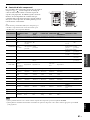
AXION 2078
BRAINWAVE 2096
BRANDT 2073, 2085
BROKSONIC 2060
BUSH 2075, 2078, 2112
CENTREX 2077
CLASSIC 2078
CLATRONIC 2075
COBY 2078
C-TECH 2074
CYBERHOME
2025, 2079, 2091
DAEWOO 2092, 2098
DANSAI 2096
DAYTEK 2080, 2089
DEC 2075
DENON 2030, 2102, 2103
DENVER 2075, 2076
DIAMOND 2074
DK DIGITAL 2094
DUAL 2078
D-VISION 2096
DVX 2074
ELTA 2096
EUROLINE 2096
FUNAI 2052, 2058
GLOBAL SOLUTIONS
2074
GLOBAL SPHERE
2074
GOODMANS 2075, 2077, 2078
GRUNDIG 2077, 2098
H&B 2075
HAAZ 2074
HE 2078
HITACHI 2032, 2072
HOME ELECTRONICS
2078
INNOVATION 2072
IRRADIO 2134
JDB 2078
JVC 2033, 2045, 2053,
2073, 2099
KENWOOD 2030, 2097
KINGAVON 2075
KODA 2075
LAWSON 2074
LENCO 2075
LG 2084, 2087
LIFETEC 2072
LIMIT 2074
LOGICLAB 2074
LUXOR 2077
MAGNAVOX 2037, 2073, 2075
MAGNUM 2072
MBO 2078
MEDION 2072
MICROMAXX
2072
MICROMEDIA
2073
MICROSTAR 2072
MITSUBISHI 2035
MIZUDA 2075
MUSTEK 2078
NAIKO 2077
ONKYO 2073, 2135
ORAVA 2075
P&B 2075
PACIFIC 2074
PANASONIC 2030, 2040, 2054,
2057, 2105, 2110
PHILIPS 2019, 2026, 2046,
2073, 2081, 2090
PIONEER 2036, 2082
PROLINE 2077
PROVISION 2075
RCA 2031, 2042, 2050,
2051
RED STAR 2076
REOC 2074
ROADSTAR 2075, 2078, 2086
ROWA 2077
SABA 2085
SABAKI 2074
SAMSUNG 2032, 2041, 2104,
2113
SANSUI 2074
SANYO 2095
SCANMAGIC 2078
SCIENTIFIC LABS
2074
SCOTT 2088
SEG 2074, 2086
SHARP 2034, 2043, 2059,
2093, 2106
SILVA 2076
SINGER 2074
SKYMASTER 2074, 2078
SKYWORTH 2076
SM ELECTRONIC
2074, 2078
SONY 2028, 2029, 2039,
2083, 2107
SOUNDMASTER
2074
SOUNDMAX 2074
STANDARD 2074
STAR CLUSTER
2074
STARMEDIA 2075
SUPERVISION
2074, 2078
SYLVANIA 2052, 2058
SYNN 2074
TCM 2072
TEAC 2074
TEC 2076
TECHNICS 2030
TECHNIKA 2096
TECHNOSONIC
2096
TEVION 2072, 2074
THOMSON 2085, 2109
TOKAI 2076
TOSHIBA 2026, 2044, 2048,
2056, 2073, 2108,
2111
UNITED 2078
VOXSON 2078
WHARFEDALE
2074
XLOGIC 2074
YAKUMO 2077
YAMADA 2077
YAMAHA 2000, 2001, 2003,
2030, 2101
YUKAI 2078
ZENITH 2038, 2047, 2073
DVD-DVR
PANASONIC 2067
PIONEER 2114
SAMSUNG 2115
TOSHIBA 2068
DVD/LD COMBO
PIONEER 2036
DVD RECORDER
APEX 2024
JVC 2070
LG 2071
PANASONIC 2020, 2065, 2066,
2067
PHILIPS 2019, 2061, 2062,
2063
PIONEER 2021
RCA 2018
SONY 2022, 2064
TOSHIBA 2068
YAMAHA 2023
YUKAI 2069
DVR
ABS 2132
ALIENWARE 2132
CYBERPOWER
2132
DELL 2132
DIRECTV 2123, 2128, 2129,
2133
DISH NETWORK
2126, 2127
DISHPRO 2126
ECHOSTAR 2126, 2127
EXPRESSVU 2126
GATEWAY 2132
GOI 2126
HEWLETT PACKARD
2132
HITACHI 2008
HOWARD COMPUTERS
2132
HTS 2126
HUGHES 2123, 2128
HUMAX 2123
HUSH 2132
IBUYPOWER 2132
JVC 2126, 2127
LINKSYS 2132
MEDIA CENTER PC
2132
MICROSOFT 2132
MIND 2132
NIVEUS MEDIA
2132
NORTHGATE 2132
PANASONIC 2015, 2016, 2017,
2120
PHILIPS 2117, 2121, 2123,
2128
PIONEER 2012, 2013, 2014
PROSCAN 2129
RCA 2116, 2124, 2129,
2133
REPLAYTV 2118, 2119, 2120
SHARP 2009, 2010
SONIC BLUE 2119, 2120
SONY 2005, 2006, 2007,
2122, 2130, 2131,
2132
STACK 9 2132
SYSTEMAX 2132
TAGAR SYSTEMS
2132
TIVO 2116, 2121, 2122,
2123, 2130, 2131
TOSHIBA 2004, 2125, 2132
TOUCH 2132
ULTIMATETV 2133
VIEWSONIC 2132
VOODOO 2132
YAMAHA 2011
ZT GROUP 2132
LD PLAYER
YAMAHA 2002
CD PLAYER
YAMAHA 5000, 5013
CD RECORDER
YAMAHA 5001
MD
YAMAHA 5002, 5003, 5004
TAPE DECK
YAMAHA 5005, 5006
TUNER
YAMAHA 5007, 5008, 5009,
5010, 5012, 5014
RX-V461_E-cv.fm Page 1 Friday, May 11, 2007 2:59 PM

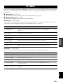
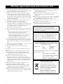
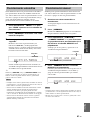
CAUTION: READ THIS BEFORE OPERATING YOUR UNIT.
En
1 To assure the finest performance, please read this manual
carefully. Keep it in a safe place for future reference.
2 Install this sound system in a well ventilated, cool, dry, clean
place – away from direct sunlight, heat sources, vibration,
dust, moisture, and/or cold. Allow ventilation space of at least
30 cm on the top, 20 cm on the left and right, and 20 cm on
the back of this unit.
3 Locate this unit away from other electrical appliances, motors,
or transformers to avoid humming sounds.
4 Do not expose this unit to sudden temperature changes from
cold to hot, and do not locate this unit in a environment with
high humidity (i.e. a room with a humidifier) to prevent
condensation inside this unit, which may cause an electrical
shock, fire, damage to this unit, and/or personal injury.
5 Avoid installing this unit where foreign object may fall onto
this unit and/or this unit may be exposed to liquid dripping or
splashing. On the top of this unit, do not place:
– Other components, as they may cause damage and/or
discoloration on the surface of this unit.
– Burning objects (i.e. candles), as they may cause fire,
damage to this unit, and/or personal injury.
– Containers with liquid in them, as they may fall and liquid
may cause electrical shock to the user and/or damage to
this unit.
6 Do not cover this unit with a newspaper, tablecloth, curtain,
etc. in order not to obstruct heat radiation. If the temperature
inside this unit rises, it may cause fire, damage to this unit,
and/or personal injury.
7 Do not plug in this unit to a wall outlet until all connections
are complete.
8 Do not operate this unit upside-down. It may overheat,
possibly causing damage.
9 Do not use force on switches, knobs and/or cords.
10 When disconnecting the power cable from the wall outlet,
grasp the plug; do not pull the cord.
11 Do not clean this unit with chemical solvents; this might
damage the finish. Use a clean, dry cloth.
12 Only voltage specified on this unit must be used. Using this
unit with a higher voltage than specified is dangerous and may
cause fire, damage to this unit, and/or personal injury. Yamaha
will not be held responsible for any damage resulting from use
of this unit with a voltage other than specified.
13 To prevent damage by lightning, keep the power cord and
outdoor antennas disconnected from a wall outlet or the unit
during a lightning storm.
14 Do not attempt to modify or fix this unit. Contact qualified
Yamaha service personnel when any service is needed. The
cabinet should never be opened for any reasons.
15 When not planning to use this unit for long periods of time
(i.e. vacation), disconnect the AC power plug from the wall
outlet.
16 Install this unit near the AC outlet and where the AC power
plug can be reached easily.
17 Be sure to read the “Troubleshooting” section on common
operating errors before concluding that this unit is faulty.
18 Before moving this unit, press STANDBY/ON to set this unit
in the standby mode, and disconnect the AC power plug from
the wall outlet.
19 The batteries shall not be exposed to excessive heat such as
sunshine, fire or like.
20 Excessive sound pressure from earphones and headphones can
cause hearing loss.
■ For U.K. customers
If the socket outlets in the home are not suitable for the
plug supplied with this appliance, it should be cut off and
an appropriate 3 pin plug fitted. For details, refer to the
instructions described below.
The plug severed from the mains lead must be destroyed, as a
plug with bared flexible cord is hazardous if engaged in a live
socket outlet.
■ Special Instructions for U.K. Model
Caution: Read this before operating your unit.
WARNING
TO REDUCE THE RISK OF FIRE OR ELECTRIC
SHOCK, DO NOT EXPOSE THIS UNIT TO RAIN
OR MOISTURE.
This unit is not disconnected from the AC power
source as long as it is connected to the wall outlet, even
if this unit itself is turned off by STANDBY/ON. This
state is called the standby mode. In this state, this unit
is designed to consume a very small quantity of power.
Note
IMPORTANT
THE WIRES IN MAINS LEAD ARE COLOURED IN
ACCORDANCE WITH THE FOLLOWING CODE:
Blue: NEUTRAL
Brown: LIVE
As the colours of the wires in the mains lead of this apparatus
may not correspond with the coloured markings identifying
the terminals in your plug, proceed as follows:
The wire which is coloured BLUE must be connected to the
terminal which is marked with the letter N or coloured
BLACK. The wire which is coloured BROWN must be
connected to the terminal which is marked with the letter L or
coloured RED.
Making sure that neither core is connected to the earth
terminal of the three pin plug.
This symbol mark is according to the
EU directive 2002/96/EC.
This symbol mark means that electrical
and electronic equipment, at their end-
of-life, should be disposed of separately
from your household waste.
Please act according to your local rules
and do not dispose of your old products
with your normal household waste.

1 En
English
PREPARATIONINTRODUCTION
BASIC
OPERATION
ADVANCED
OPERATION
ADDITIONAL
INFORMATION
APPENDIX
Features ................................................................... 2
Getting started ........................................................ 3
Quick start guide .................................................... 4
Preparation: Check the items ..................................... 4
Step 1: Set up your speakers...................................... 5
Step 2: Connect your DVD player
and other components............................................ 6
Step 3: Turn on the power
and press SCENE 1 button .................................... 8
What do you want to do with this unit?..................... 9
Connections........................................................... 10
Rear panel ................................................................ 10
Placing speakers....................................................... 11
Connecting speakers ................................................ 12
Information on jacks and cable plugs ...................... 14
Information on HDMI™.......................................... 15
Connecting video components................................. 16
Connecting audio components................................. 19
Using the VIDEO AUX jacks on the front panel .... 20
Connecting the FM and AM antennas ..................... 20
Connecting the power cable..................................... 21
Turning on and off the power .................................. 21
Front panel display .................................................. 22
Optimizing the speaker setting
for your listening room .................................... 24
Using AUTO SETUP .............................................. 24
Selecting the SCENE templates........................... 28
Selecting the desired SCENE template.................... 28
Creating your original SCENE templates................ 31
Playback ................................................................ 32
Basic operations....................................................... 32
Additional operations............................................... 33
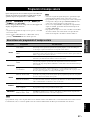
Sound field programs ........................................... 37
Sound field program descriptions............................ 37
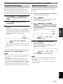
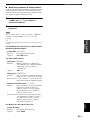
FM/AM tuning ...................................................... 40
Automatic tuning ..................................................... 40
Manual tuning.......................................................... 40
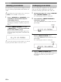
Automatic preset tuning........................................... 41
Manual preset tuning ............................................... 41
Selecting preset stations........................................... 42
Exchanging preset station ........................................ 42
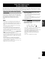
Radio Data System tuning
(Europe model only)......................................... 43
Displaying the Radio Data System information ...... 43
Selecting the Radio Data System
program type (PTY SEEK mode) ....................... 44
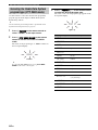
Using the enhanced other networks
(EON) data service .............................................. 45
Using a USB memory device or
a USB portable audio player ........................... 46
Playback operation................................................... 46
Recording .............................................................. 48
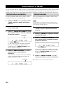
SET MENU ............................................................49
Using SET MENU................................................... 50
1 SOUND MENU.................................................... 51
2 INPUT MENU...................................................... 55
3 OPTION MENU................................................... 57
Remote control features........................................59
Using remote control on the SCENE feature........... 59
Controlling this unit, a TV, or other components.... 60
Setting remote control codes ................................... 62
Advanced setup......................................................63
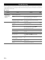
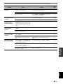
Troubleshooting.....................................................64
Glossary..................................................................71
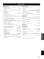
Specifications .........................................................73
Index.......................................................................74
(at the end of this manual)
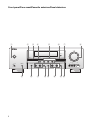
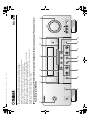
Front panel................................................................i
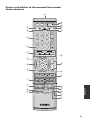
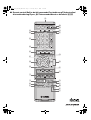
Remote control ....................................................... ii
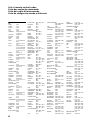
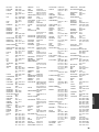
List of remote control codes ................................. iii
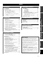
Contents
INTRODUCTION
PREPARATION
BASIC OPERATION
ADVANCED OPERATION
ADDITIONAL INFORMATION
APPENDIX
About this manual
• y indicates a tip for your operation.
• Some operations can be performed by using either the
buttons on the front panel or the ones on the remote control.
In case the button names differ between the front panel and
the remote control, the button name on the remote control is
given in parentheses.
• This manual is printed prior to production. Design and
specifications are subject to change in part as a result of
improvements, etc. In case of differences between the
manual and product, the product has priority.
•“
9
SPEAKERS” or “
A
MULTI CH IN” (example)
indicates the name of the parts on the front panel or the
remote control. Refer to the attached sheet or the appendix
pages at the end of this manual for the information about
each position of the parts.
•The symbol “☞ ” with page number(s) indicates the
corresponding reference page(s).

Features
2 En
Built-in 5-channel power amplifier
◆ Minimum RMS output power
[Front, Center, Surround channels]
100 W (1 kHz, 0.9% THD, 6 Ω)
SCENE select function
◆ Preset SCENE templates for various situations
◆ SCENE template customizing capability
Decoders and DSP circuits
◆ Proprietary Yamaha technology for the creation of multi-
channel surround sound
◆ Compressed Music Enhancer mode to improve the sound
quality of compression artifacts (such as the MP3 format) to
that of a high-quality stereo
◆ Dolby Digital decoder
◆ Dolby Pro Logic/Dolby Pro Logic II decoder
◆ DTS decoder
◆ Virtual CINEMA DSP
◆ SILENT CINEMA
™
Sophisticated FM/AM tuner
◆ 40-station random and direct preset tuning
◆ Automatic preset tuning
◆ Radio Data System capability (Europe model only)
HDMI (High-Definition Multimedia Interface)
◆ HDMI interface for standard, enhanced or high-definition
video (includes 1080p video signal transmission)
USB features
◆ USB port to connect a USB memory device or a USB portable
audio player
◆ MP3, WMA and WAV capability
Other features
◆ YPAO (Yamaha Parametric Room Acoustic Optimizer) for
automatic speaker setup
◆ 192-kHz/24-bit D/A converter
◆ Direct Stereo mode for pure hi-fi sound for analog and PCM
2-channel sources
◆ 6 additional input jacks for discrete multi-channel input
◆ OSD (on-screen display) menus that allow you to optimize
this unit to suit your individual audiovisual system
◆ Component video input/output capability
(3 COMPONENT VIDEO INs and 1 MONITOR OUT)
◆ S-video signal input/output capability
◆ Optical and coaxial digital audio signal jacks
◆ Sleep timer
◆ Cinema and music night listening modes
◆ Remote control with preset remote control codes
Manufactured under license from Dolby Laboratories.
“Dolby”, “Pro Logic”, and the double-D symbol are trademarks
of Dolby Laboratories.
“SILENT CINEMA” is a trademark of YAMAHA
CORPORATION.
“HDMI”, the “HDMI” logo and “High-Definition Multimedia
Interface” are trademarks or registered trademarks of HDMI
Licensing LLC.
“DTS” and “DTS Digital Surround” are registered trademarks of
DTS, Inc.
This unit is equipped with the technologies developed by Analog
Devices, Inc. and others. It is strictly prohibited to use this unit
for use other than audiovisual purposes.
Features

Getting started
3 En
English
INTRODUCTION
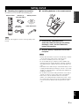
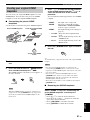
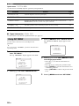
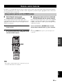
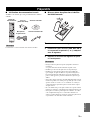
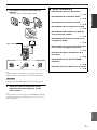
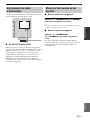
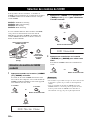
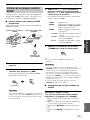
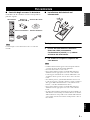
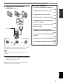
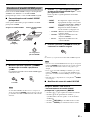
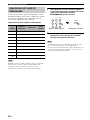
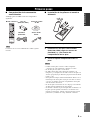
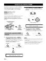
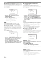
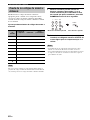
■ Checking the supplied accessories
Check that you received all of the following parts.
The form of the supplied accessories varies depending on the
models.
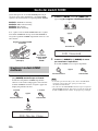
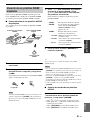
■ Installing batteries in the remote control
1 Take off the battery compartment cover.
2 Insert the two supplied batteries
(AAA, R03, UM-4) according to the polarity
markings (+ and –) on the inside of the
battery compartment.
3 Snap the battery compartment cover back
into place.
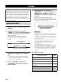
• Change all of the batteries if you notice the following condition:
– the operation range of the remote control decreases.
• Do not use an old battery and a new one together.
• Do not use different types of batteries (such as alkaline and
manganese batteries) together. Read the packaging carefully as
these different types of batteries may have the same shape and
color.
• If the batteries have leaked, dispose of them immediately. Avoid
touching the leaked material or letting it come into contact with
clothing, etc. Clean the battery compartment thoroughly before
installing new batteries.
• Do not throw away batteries with general house waste; dispose
of them correctly in accordance with your local regulations.
• If the remote control is without batteries for more than 2
minutes, or if exhausted batteries remain in the remote control,
the contents of the memory may be cleared. When the memory
is cleared, insert new batteries and set up the remote control
code.
Getting started
Note
REC
SUR.DECODE NIGHT
STRAIGHTENHANCERl PROG h
TV MUTE
TV INPUT
TV VOL
TV CH
POWER
AMP
STANDBY
POWER
AUDIO SEL
SLEEP MUTE
MULTI CH IN
POWER
8
10
7
09
65
4321
ENT
DVD DTV/CBL DVR
CD MD/CD-R
TUNER
MENU
VOLUME
TITLE
ENTER
BAND LEVEL
DISPLAY
RETURN
AVTV
SCENE
4321
MODE – PTY SEEK – START
FREQ/TEXT
DIRECT ST.
EON
V-AUX USB
Remote control
Batteries (2)
(AAA, R03, UM-4)
Indoor FM antenna
AM loop antenna
Optimizer
microphone
Notes
1
3
2

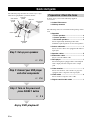
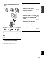
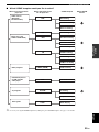
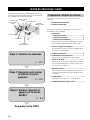
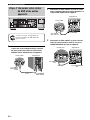
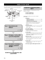
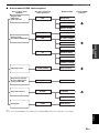
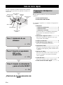
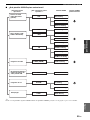
Quick start guide
4 En
The following steps describe the easiest way to enjoy
DVD movie playback in your home theater.
In these steps, you need the following supplied
accessories.
❏ Indoor FM antenna
❏ AM loop antenna
The following items are not included in the package of this
unit.
❏ Speakers
❏ Front speakers ...................................... 2
❏ Center speaker ...................................... 1
❏ Surround speakers ............................... 2
Select magnetically shielded speakers. The
minimum required speakers are two front speakers.
❏ Active subwoofer ...................................... 1
Select an active subwoofer equipped with an RCA
input jack.
❏ Speaker cables .......................................... 5
❏ Subwoofer cable ........................................ 1
Select a monaural RCA cable.
❏ DVD player ................................................. 1
Select DVD player equipped with coaxial digital
audio output jack and composite video output
jack.
❏ Video monitor............................................. 1
Select a TV monitor, video monitor or projector
equipped with a composite video input jack.
❏ Video cable ................................................ 2
Select an RCA composite video cable.
❏ Digital coaxial audio cable ....................... 1
Quick start guide
Front right
speaker
Subwoofer
Surround left
speaker
Front left
speaker
Surround right
speaker
Center speaker
DVD player
Video monitor
Enjoy DVD playback!
Step 1: Set up your speakers
Step 2: Connect your DVD player
and other components
Step 3: Turn on the power and
press SCENE 1 button
☞
P. 6
☞
P. 8
☞
P. 5
Preparation: Check the items

Quick start guide
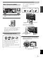
5 En
English
INTRODUCTION
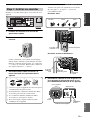
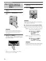
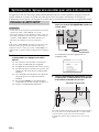
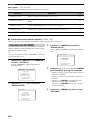
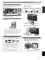
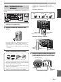
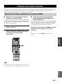
Place your speakers in the room and connect them to this
unit.
1 Place your speakers and subwoofer in the
room.
2 Connect speaker cables to each speaker.
Cables are colored or shaped differently, perhaps with
a stripe, groove or ridge. Connect the striped
(grooved, etc.) cable to the “+” (red) terminals of
your speaker. Connect the plain cable to the “–”
(black) terminals.
3 Connect each speaker cable to the
corresponding speaker terminal of this unit.
1 Make sure that this unit and the subwoofer are
unplugged from the AC wall outlets.
2 Twist the exposed wires of the speaker cables
together to prevent short circuits.
3 Do not let the bare speaker wires touch each other.
4 Do not let the bare speaker wires touch any metal
part of this unit.
Be sure to connect the left channel (L), right channel
(R), “+” (red) and “–” (black) properly.
Front speakers
Center and surround speakers
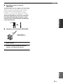
4 Connect the subwoofer cable to the input
jack of the subwoofer and the SUBWOOFER
OUTPUT jack of this unit.
Step 1: Set up your speakers
MULTI CH INPUT
COMPONENT VIDEO
DIGITAL INPUT
VIDEO
ANTENNA
SPEAKERS AC OUTLETS
LR LR
SURROUND CENTER FRONT B
AUDIO OUTPUT
L
1
2
3
R
L
R
L
R
DVD
DTV/CBL
D
V
R
CD
SUB
WO
O
FER
IN
OU
T
CENTER
SUBWOOFER
SURROUNDFRONT
DVD
OPTICAL
COAXIAL
CD
DTV/
CBL
DVD
P
R
P
B
DTV/CBL DVR DVD
S VIDEO
VIDEO
DVR
AM
FRONT A
GND
FM
UNBAL.
75
IN OUT
DTV/CBLMONITOR
OUT
MONITOR
OUT
MD/
CD-R
OU
T
(
REC)
IN
(PLAY)
HDMI
DVDOUT DTV/CBL
12 3 4
To the front
right speaker
Front left speaker
Loosen Insert Tighten
To the
surround
right speaker
To the surround
left speaker
To the center
speaker
OUTPUT
SUB
WOOFER
IN
(PLAY)
OUT
(REC)
MD/
CD-R
SUBWOOFER
OUTPUT jack
Subwoofer cable
Input jack
AV receiver
Subwoofer

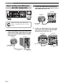
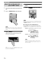
Quick start guide
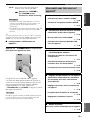
6 En
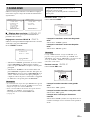
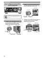
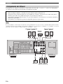
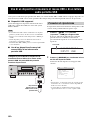
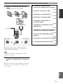
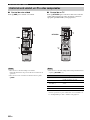
1 Connect the digital coaxial audio cable to the
digital coaxial audio output jack of your DVD
player and the DVD DIGITAL INPUT COAXIAL
jack of this unit.
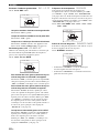
2 Connect the video cable to the composite
video output jack of your DVD player and the
DVD VIDEO jack of this unit.
3 Connect the video cable to the video input
jack of your video monitor and the VIDEO
MONITOR OUT jack of this unit.
Step 2: Connect your DVD player
and other components
AC OUTLETS
MULTI CH INPUT
COMPONENT VIDEO
DIGITAL INPUT
VIDEO
ANTENNA
SPEAKERS
LR LR
SURROUND CENTER FRONT B
AUDIO OUTPUT
L
1
2
3
R
L
R
L
R
DVD
DTV/CBL
D
V
R
CD
S
U
B
WO
O
FER
IN
O
U
T
CENTER
SUBWOOFER
SURROUNDFRONT
DVD
OPTICAL
COAXIAL
CD
DTV/
CBL
DVD
P
R
P
B
Y
DTV/CBL DVR DVD
S VIDEO
VIDEO
DVR
AM
FRONT A
GND
FM
UNBAL.
75
IN OUT
DTV/CBLMONITOR
OUT
MONITOR
OUT
MD/
CD-R
O
U
T
(RE
C
)
IN
(PL
A
Y)
HDMI
DVDOUT DTV/CBL
Make sure that this unit and the DVD
player are unplugged from the AC wall
outlets.
Digital coaxial
audio output jack
Digital coaxial audio
cable
DVD DIGITAL INPUT
COAXIAL jack
DVD player
AV receiver
Composite video
output jack
Video cable
DVD VIDEO jack
DVD player
AV receiver
L/MONO
AUDIO AUDIO
COLOR STREAM HD
VIDEO
VIDEO-1 IN IN
S-VIDEO
RYP
B
P
R
RL/MONO
Video monitor
AV receiver
Video input jack
VIDEO MONITOR OUT
jack
Video cable

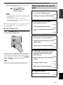
Quick start guide
7 En
English
INTRODUCTION
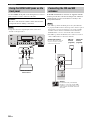
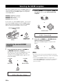
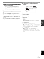
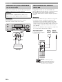
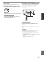
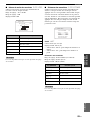
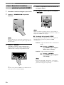
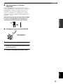
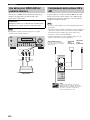
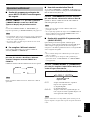
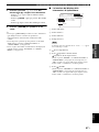
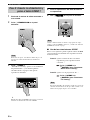
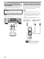
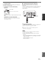
4 Connect the FM and AM antennas to this
unit.
See page 20 for the details.
y
The wire of the AM loop antenna does not have any polarity and
you can connect either end of the wire to AM and GND terminal.
The shape of the AM and GND terminals may vary depending on
the unit.
5 Connect the power plug of this unit and other
components into the AC wall outlet.
y
This unit is equipped with AC OUTLETS for the power supply of
the other components. See page 21 for details.
Note
Indoor FM antenna
AM loop antenna
Open the lever Insert Close the lever
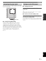
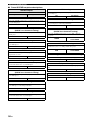
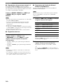
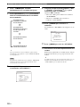
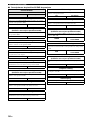
■ For further connections
• Using the other kind of speaker
combinations
☞ P. 12
• Connecting a video monitor
☞ P. 16
• Connecting a DVD player
☞ P. 16
• Connecting a DVD recorder
☞ P. 16
• Connecting a cable TV or a satellite tuner
☞ P. 16
• Connecting a CD player and an MD
recorder
☞ P. 19
• Connecting a DVD player via analog
multi-channel audio connection
☞ P. 19
• Using the VIDEO AUX jacks on the front
panel
☞ P. 20
• Connecting an outdoor FM/AM antenna
☞ P. 20
• Using the USB jack on the front panel
☞ P. 46

Quick start guide
8 En
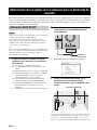
1 Turn on the video monitor connected to this
unit.
2 Press
1
STANDBY/ON on the front panel.
In the standby mode, this unit consumes a small amount of
power in order to receive infrared signals from the remote
control.
3 Press
F
SCENE 1.
“DVD Movie Viewing” appears in the front panel
display, and this unit automatically optimize own
status for the DVD playback.
y
The indicator on the selected SCENE button lights up while
this unit is in the SCENE mode.
4 Start playback of the desired DVD on your
player.
5 Rotate
8
VOLUME to adjust the volume.
When you change the input source or sound field program, the
SCENE mode is deactivated, and the indicator on the selected
SCENE button turns off.
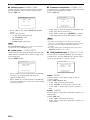
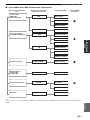
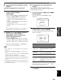
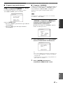
■ Using the other SCENE buttons
In the following cases, try pressing the corresponding
SCENE button to enjoy playback of the desired sources.
Case A: “I want to listen to a music disc from the
connected DVD player...”
Press
F
SCENE 2 (or
E
SCENE 2) to select
“Music Disc Listening”.
Case B: “I want to watch a TV program...”
Press
F
SCENE 3 (or
E
SCENE 3) to select
“TV Viewing”.
To use the “TV Viewing” template, you must connect a
cable TV or a satellite tuner to this unit in advance. See
page 16 for details.
Step 3: Turn on the power and
press SCENE 1 button
Note
Note
Note

Quick start guide
9 En
English
INTRODUCTION
Case C: “I want to listen to a music program from
the FM radio station...”
Press
F
SCENE 4 (or
E
SCENE 4) to select
“Radio Listening”.
• To use the “Radio Listening” template, you must tune into
the desired radio station in advance. See pages 40 to 42 for
tuning information.
• To achieve the best possible reception, orient the
connected AM loop antenna, or adjust the position of the
end of the indoor FM antenna.
y
If you cannot find the desired situation, you can select and change
the assigned SCENE template for the SCENE buttons. See
page 28 for details.
■ After using this unit...
Press
1
STANDBY/ON on the front panel to set
this unit to the standby mode.
This unit is set to the standby mode. In the standby mode,
this unit consumes a small amount of power in order to
receive infrared signals from the remote control. To turn
on this unit from the standby mode, press
1
STANDBY/
ON (or
M
POWER). See page 21 for details.
In the standby mode, this unit consumes a small amount of power
in order to receive infrared signals from the remote control.
Notes
Note
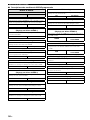
What do you want to do with this
unit?
■ Customizing the SCENE templates
• Using various SCENE templates
☞ P. 28
• Creating your original SCENE templates
☞ P. 31
■ Using various input sources
• Basic controls of this unit
☞ P. 32
• Enjoying FM/AM radio programs
☞ P. 40
• Using your USB portable device with this
unit
☞ P. 46
■ Using various sound features
• Using various sound field programs
☞ P. 37
• Using the pure direct mode for the high
fidelity sound
☞ P. 34
• Customizing the sound field programs
☞ P. 39
■ Adjusting the parameters of this unit
• Automatically optimizing the speaker
parameters for your listening room
(AUTO SETUP)
☞ P. 24
• Manually adjusting various parameters of
this unit
☞ P. 49
• Setting the remote control
☞ P. 59
• Adjusting the advanced parameters
☞ P. 63
■ Additional features
Automatically turning off this unit
☞ P. 36

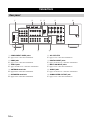
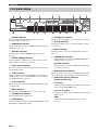
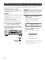
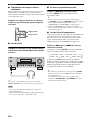
Connections
10 En
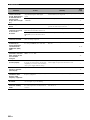
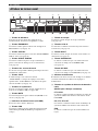
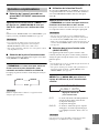
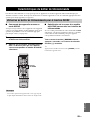
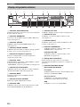
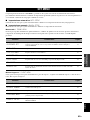
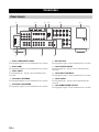
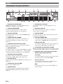
1 COMPONENT VIDEO jacks
See page 18 for connection information.
2 HDMI jacks
See page 17 for connection information.
3 VIDEO jacks
See pages 16 and 18 for connection information.
4 ANTENNA terminals
See page 20 for connection information.
5 SPEAKERS terminals
See page 12 for connection information.
6 AC OUTLETS
See page 21 for connection information.
7 DIGITAL INPUT jacks
See pages 16 and 19 for connection information.
8 MULTI CH INPUT jacks
See page 19 for connection information.
9 AUDIO jacks
See pages 16 and 19 for connection information.
0 SUBWOOFER OUTPUT jack
See page 12 for connection information.
Connections
Rear panel
MULTI CH INPUT
COMPONENT VIDEO
DIGITAL INPUT
VIDEO
ANTENNA
SPEAKERS
L
R
L
R
SURROUND CENTER FRONT B
AUDIO OUTPUT
L
1
2
3
R
L
R
L
R
DVD
DT
V
/CBL
D
V
R
C
D
S
UB
W
OO
F
ER
IN
O
UT
CENTER
SUBWOOFER
SURROUNDFRONT
DVD
OPTICAL
COAXIAL
CD
DTV/
CBL
DVD
P
R
P
B
Y
DTV/CBL DVR DVD
S VIDEO
VIDEO
DVR
AM
FRONT A
GND
FM
UNBAL.
75
IN OUT
DTV/CBLMONITOR
OUT
MONITOR
OUT
HDMI
M
D/
CD-R
O
UT
(
R
E
C
)
IN
(PLAY)
AC OUTLETS
DVDOUT DTV/CBL
7 8 9 0
1
2 3 4 5 6

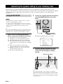
11 En
Connections
English
PREPARATION
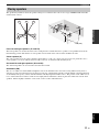
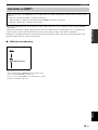
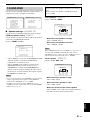
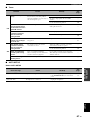
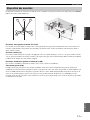
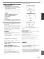
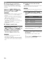
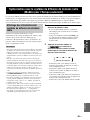
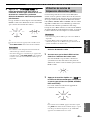
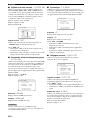
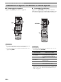
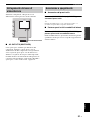
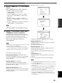
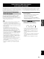
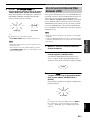
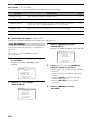
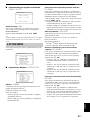
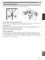
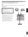
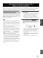
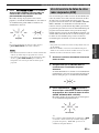
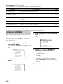
The speaker layout below shows the speaker setting we recommend. You can use it to enjoy CINEMA DSP and multi-
channel audio sources.
Front left and right speakers (FL and FR)
The front speakers are used for the main source sound plus effect sounds. Place these speakers at an equal distance from the
ideal listening position. The distance of each speaker from each side of the video monitor should be the same.
Center speaker (C)
The center speaker is for the center channel sounds (dialog, vocals, etc.). If for some reason it is not practical to use a
center speaker, you can do without it. Best results, however, are obtained with the full system.
Surround left and right speakers (SL and SR)
The surround speakers are used for effect and surround sounds.
Subwoofer (SW)
The use of a subwoofer with a built-in amplifier, such as the Yamaha Active Servo Processing Subwoofer System, is
effective not only for reinforcing bass frequencies from any or all channels, but also for high fidelity sound reproduction
of the LFE (low-frequency effect) channel included in Dolby Digital and DTS sources. The position of the subwoofer is
not so critical, because low bass sounds are not highly directional. But it is better to place the subwoofer near the front
speakers. Turn it slightly toward the center of the room to reduce wall reflections.
Placing speakers
60˚
30˚
FL
FR
C
SL
SR
SR
80˚
SL
FR
FL
C
SL
SR
SW
1.8 m (6 ft)

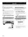
12 En
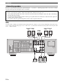
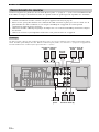
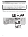
Connections
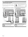
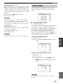
Be sure to connect the left channel (L), right channel (R), “+” (red) and “–” (black) properly. If the connections are faulty,
this unit cannot reproduce the input sources accurately.
A speaker cable is actually a pair of insulated cables running side by side. Cables are colored or shaped differently, perhaps with a stripe,
groove or ridge. Connect the striped (grooved, etc.) cable to the “+” (red) terminals of this unit and your speaker. Connect the plain cable
to the “–” (black) terminals.
Connecting speakers
Caution
• Before connecting the speakers, make sure that this unit is turned off (see page 21).
• Do not let the bare speaker wires touch each other or let them touch any metal part of this unit. This could damage
this unit and/or the speakers.
• Use the magnetically shielded speakers. If this type of speaker still creates interference with the monitor, place the
speakers away from the monitor.
• Use speakers with the specified impedance shown on the rear panel of this unit.
Note
Subwoofer
Center speaker
MULTI CH INPUT
COMPONENT VIDEO
DIGITAL INPUT
VIDEO
ANTENNA
SPEAKERS
L
R
L
R
SURROUND CENTER FRONT B
AUDIO OUTPUT
L
1
2
3
R
L
R
L
R
DT
V
/CBL
D
VR
C
D
SUB
W
OOF
ER
IN
OUT
CENTER
SUBWOOFER
SURROUNDFRONT
DVD
OPTICAL
COAXIAL
CD
DTV/
CBL
DVD
P
R
P
B
Y
DTV/CBL DVR DVD
DVD
S VIDEO
VIDEO
DVR
AM
FRONT A
GND
FM
UNBAL.
75
IN OUT
DTV/CBLMONITOR
OUT
MONITOR
OUT
M
D/
CD
-
R
O
UT
(
R
E
C
)
IN
(PLAY)
AC OUTLETS
HDMI
DVDOUT DTV/CBL
Subwoofer
Front speakers (A)
LeftRight
Center
speaker
Front speakers (B)
LeftRight
Surround speakers
LeftRight

13 En
Connections
English
PREPARATION
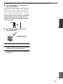
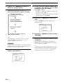
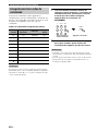
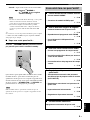
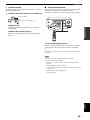
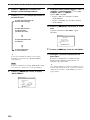
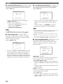
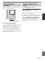
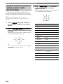
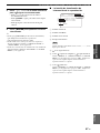
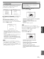
■ Before connecting to the SPEAKERS
terminal
A speaker cord is actually a pair of insulated cables
running side by side. Cables are colored or shaped
differently, perhaps with a stripe, groove or ridges.
Connect the striped (grooved, etc.) cable to the “+” (red)
terminals of this unit and your speaker. Connect the plain
cable to the “–” (black) terminals.
Remove approximately 10 mm (3/8”) of insulation
from the end of each speaker cable and then
twist the bare wires of the cable together to
prevent short circuits.
■ Connecting to the SPEAKERS terminals
1 Loosen the knob.
2 Insert the bare end of the speaker wire into
the hole on the terminal.
3 Tighten the knob to secure the wire.
10 mm (3/8”)
1
2
3
Red: positive (+)
Black: negative (–)

14 En
Connections
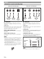
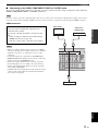
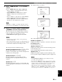
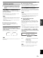
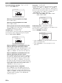
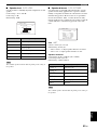
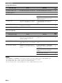
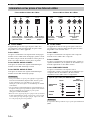
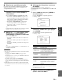
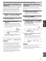
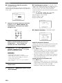
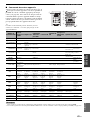
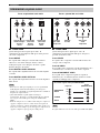
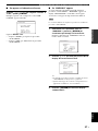
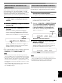
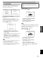
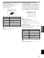
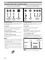
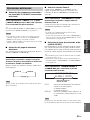
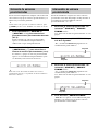
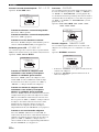
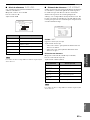
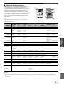
■ Audio jacks
This unit has three types of audio jacks. Connection
depends on the availability of audio jacks on your other
components.
AUDIO jacks
For conventional analog audio signals transmitted via left
and right analog audio cables. Connect red plugs to the
right jacks and white plugs to the left jacks.
DIGITAL AUDIO COAXIAL jacks
For digital audio signals transmitted via coaxial digital
audio cables.
DIGITAL AUDIO OPTICAL jacks
For digital audio signals transmitted via optical digital
audio cables.
• You can use the digital jacks to input PCM, Dolby Digital and
DTS bitstreams. All digital input jacks are compatible with
digital signals with up to 96 kHz of sampling frequency.
• This unit handles digital and analog signals independently. Thus
audio signals input at the digital jacks are not output at the
analog AUDIO OUT (REC) jacks.
• Pull out the cap from the optical jack before you connect the
optical digital audio cable. Do not discard the cap. When you
are not using the optical jack, be sure to put the cap back in
place. This cap protects the jack from dust.
■ Video jacks
This unit has three types of video jacks. Connection
depends on the availability of input jacks on your video
monitor.
VIDEO jacks
For conventional composite video signals transmitted via
composite video cables.
S VIDEO jacks
For S-video signals, separated into the luminance (Y) and
chrominance (C) video signals transmitted on separate
wires of S-video cables.
COMPONENT VIDEO jacks
For component signals, separated into the luminance (Y)
and chrominance (P
B, PR) video signals transmitted on
separate wires of component video cables.
The OSD signal is not output at the DVR OUT (REC) jacks.
Information on jacks and cable plugs
VIDEO S VIDEO
COMPONENT VIDEO
Y P
B
P
R
PB
Y
P
R
S
V
COAXIAL
DIGITAL AUDIO
AUDIO
OPTICAL
DIGITAL AUDIO
R
L
C
O
R
L
Left and right
analog audio
cable plugs
Optical
digital
audio cable
plug
Coaxial
digital audio
cable plug
Composite
video cable
plug
Component
video cable
plugs
Audio jacks and cable plugs Video jacks and cable plugs
(Red)(White) (Orange) (Yellow) (Green) (Blue) (Red)
S-video
cable plug
Notes
Note
PR
P
B
Y
P
R
P
B
Y
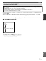
Video signal flow for MONITOR OUT
Output
(MONITOR OUT)
Input
COMPONENT
VIDEO
VIDEO
S VIDEO

15 En
Connections
English
PREPARATION
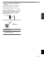
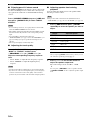
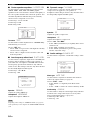
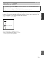
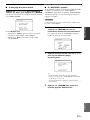
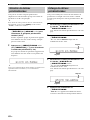
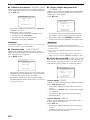
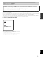
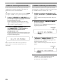
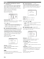
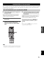
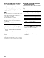
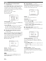
You can play back pictures by connecting your video monitor and video source component to this unit using HDMI
connections.
At that time, audio/video signals output from the connected component (such as DVD player etc.) are output to the
connected video monitor only when this unit is turned on and set to the input source (
DVD or DTV/CBL).
Furthermore, available audio/video signals depend on the specification of the connected video monitor. Refer to the
instruction manual of each connected component.
■ HDMI jack and cable plug
y
• We recommend using an HDMI cable shorter than 5 meters
(16 feet) with the HDMI logo printed on it.
• Use a conversion cable (HDMI jack
↔ DVI-D jack) to connect
this unit to other DVI components.
Information on HDMI™
Audio signals input at the HDMI jack are not output from any speaker terminals but output from the connected video
monitor.
To enjoy the sound from speakers connected to this unit,
–make an analog or digital connection besides the HDMI connection (see page 16).
–mute the volume of the connected video monitor.
HDMI cable plug
HDMI

16 En
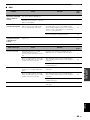
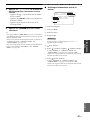
Connections
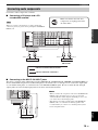
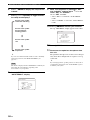
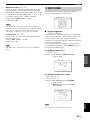
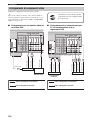
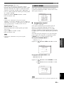
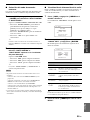
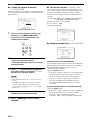
Connect the video components as follows.
y
You can also connect a video monitor, DVD player, digital TV,
and cable TV to this unit using the S VIDEO or COMPONENT
VIDEO connections (see page 17).
■ Connecting a video monitor and a DVD
player
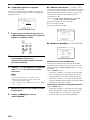
■ Connecting a cable TV/satellite tuner
and a DVD recorder
Connecting video components
Make sure that this unit and other
components are unplugged from the
AC wall outlets.
MULTI CH INPUT
COMPONENT VIDEO
DIGITAL INPUT
VIDEO
AUDIO
L
1
2
3
R
L
R
DTV/CBL
D
V
R
CD
IN
OUT
CENTER
SUBWOOFER
SURROUNDFRONT
DVD
OPTICAL
COAXIAL
CD
DTV/
CBL
DVD
P
R
P
B
Y
DTV/CBL DVR DVD
DVD
S VIDEO
VIDEO
DVR
IN OUT
DTV/CBLMONITOR
OUT
MONITOR
OUT
HDMI
DVDOUT DTV/CBL
C
L
R
VV
DVD player
Video monitor
Video in
Video out
Audio out
Audio out
indicates recommended connections
indicates alternative connections
MULTI CH INPUT
COMPONENT VIDEO
DIGITAL INPUT
VIDEO
AUDIO
L
1
3
R
L
R
DTV/CBL
D
V
R
CD
IN
OUT
CENTER
SUBWOOFER
SURROUNDFRONT
DVD
OPTICAL
COAXIAL
CD
DTV/
CBL
DVD
P
R
P
B
Y
DTV/CBL DVR DVD
DVD
S VIDEO
VIDEO
DVR
IN OUT
DTV/CBLMONITOR
OUT
MONITOR
OUT
2
HDMI
DVDOUT DTV/CBL
L
R
L
R
L
R
VVV
O
Cable TV or
Satellite tuner
DVD recorder
Audio out
Video out
Audio out
Audio in
Audio out
Video in
Video out
indicates recommended connections
indicates alternative connections

17 En
Connections
English
PREPARATION
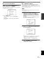
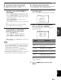
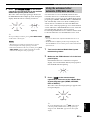
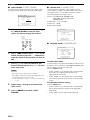
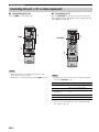
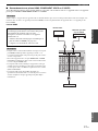
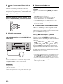
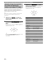
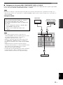
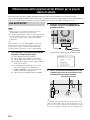
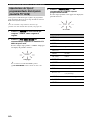
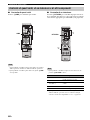
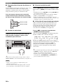
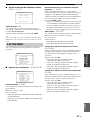
■ Connecting to the HDMI, COMPONENT VIDEO or S VIDEO jacks
You can enjoy high-quality pictures by connecting your video monitor and video source components to this unit using
HDMI, COMPONENT VIDEO or S VIDEO connections.
Be sure to connect your video components in the same way you connect your video monitor to this unit. For example, if you connect
your video monitor to this unit using a HDMI connection, connect your video components to this unit using the HDMI connection.
HDMI connection
• When you connect your TV monitor or projector via HDMI
connection, the OSD does not appear. In such cases, connect the
TV monitor or projector via component, S-video or video
connection.
• Connect the input source components to the HDMI DVD or
HDMI DTV/CBL jack to display the video images on the video
monitor connected to the HDMI OUT jack.
• Audio/video signals output from the connected component
(such as DVD player etc.) are output to the connected video
monitor only when this unit is turned on and set to the input
source (DVD or DTV/CBL).
• Available audio/video signals depend on the specification of the
connected video monitor. Refer to the instruction manual of
each connected component.
Note
Audio signals input at the HDMI jack are not output
from any speaker terminals but output from the
connected video monitor.
To enjoy the sound from speakers connected to this
unit,
–make an analog or digital connection besides the
HDMI connection (see page 16).
–mute the volume of the connected video monitor.
Notes
C
H INPUT
E
NT VIDEO VIDEO
ANTENNA
AUDIO
L
R
DT
V
/CBL
D
VR
C
D
IN
O
UT
CENTER
SUBWOOFER
SURROUND
DVR DVD
DVD
S VIDEO
VIDEO
DVR
AM
GND
FM
UNBAL.
75
IN OUT
DTV/CBLMONITOR
OUT
MONITOR
OUT
M
D
/
CD-R
(
IN
(PLAY)
HDMI
DVDOUT DTV/CBL
Video monitor
Cable TV or
satellite tuner
DVD player

18 En
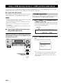
Connections
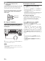
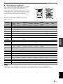
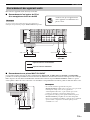
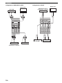
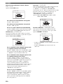
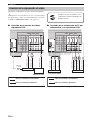
COMPONENT VIDEO connection S VIDEO connection
MULTI CH INPUT
COMPONENT VIDEO
L
R
CENTER
SUBWOOFER
SURROUNDFRONT
DVD
P
R
P
B
Y
DTV/CBL DVR MONITOR
OUT
P
R
P
B
Y
P
R
P
B
Y
P
R
P
B
Y
P
R
P
B
Y
DVD player
Video monitor
Video out
Video out
Video out
Video in
Cable TV or
satellite tuner
DVD recorder
VIDEO
AUDIO
L
R
D
TV
/CB
L
D
VR
C
D
I
N
O
UT
DVD
DVD
S VIDEO
VIDEO
DVR
IN OUT
DTV/CBL MONITOR
OUT
HDMI
DVDOUT DTV/CBL
S S
S
S S
DVD player
Video monitor
Video out
Video out
Video out
Video in
Cable TV or
satellite tuner
DVD recorder
Video in
Pagina se încarcă...
Pagina se încarcă...
Pagina se încarcă...
Pagina se încarcă...
Pagina se încarcă...
Pagina se încarcă...
Pagina se încarcă...
Pagina se încarcă...
Pagina se încarcă...
Pagina se încarcă...
Pagina se încarcă...
Pagina se încarcă...
Pagina se încarcă...
Pagina se încarcă...
Pagina se încarcă...
Pagina se încarcă...
Pagina se încarcă...
Pagina se încarcă...
Pagina se încarcă...
Pagina se încarcă...
Pagina se încarcă...
Pagina se încarcă...
Pagina se încarcă...
Pagina se încarcă...
Pagina se încarcă...
Pagina se încarcă...
Pagina se încarcă...
Pagina se încarcă...
Pagina se încarcă...
Pagina se încarcă...
Pagina se încarcă...
Pagina se încarcă...
Pagina se încarcă...
Pagina se încarcă...
Pagina se încarcă...
Pagina se încarcă...
Pagina se încarcă...
Pagina se încarcă...
Pagina se încarcă...
Pagina se încarcă...
Pagina se încarcă...
Pagina se încarcă...
Pagina se încarcă...
Pagina se încarcă...
Pagina se încarcă...
Pagina se încarcă...
Pagina se încarcă...
Pagina se încarcă...
Pagina se încarcă...
Pagina se încarcă...
Pagina se încarcă...
Pagina se încarcă...
Pagina se încarcă...
Pagina se încarcă...
Pagina se încarcă...
Pagina se încarcă...
Pagina se încarcă...
Pagina se încarcă...
Pagina se încarcă...
Pagina se încarcă...
Pagina se încarcă...
Pagina se încarcă...
Pagina se încarcă...
Pagina se încarcă...
Pagina se încarcă...
Pagina se încarcă...
Pagina se încarcă...
Pagina se încarcă...
Pagina se încarcă...
Pagina se încarcă...
Pagina se încarcă...
Pagina se încarcă...
Pagina se încarcă...
Pagina se încarcă...
Pagina se încarcă...
Pagina se încarcă...
Pagina se încarcă...
Pagina se încarcă...
Pagina se încarcă...
Pagina se încarcă...
Pagina se încarcă...
Pagina se încarcă...
Pagina se încarcă...
Pagina se încarcă...
Pagina se încarcă...
Pagina se încarcă...
Pagina se încarcă...
Pagina se încarcă...
Pagina se încarcă...
Pagina se încarcă...
Pagina se încarcă...
Pagina se încarcă...
Pagina se încarcă...
Pagina se încarcă...
Pagina se încarcă...
Pagina se încarcă...
Pagina se încarcă...
Pagina se încarcă...
Pagina se încarcă...
Pagina se încarcă...
Pagina se încarcă...
Pagina se încarcă...
Pagina se încarcă...
Pagina se încarcă...
Pagina se încarcă...
Pagina se încarcă...
Pagina se încarcă...
Pagina se încarcă...
Pagina se încarcă...
Pagina se încarcă...
Pagina se încarcă...
Pagina se încarcă...
Pagina se încarcă...
Pagina se încarcă...
Pagina se încarcă...
Pagina se încarcă...
Pagina se încarcă...
Pagina se încarcă...
Pagina se încarcă...
Pagina se încarcă...
Pagina se încarcă...
Pagina se încarcă...
Pagina se încarcă...
Pagina se încarcă...
Pagina se încarcă...
Pagina se încarcă...
Pagina se încarcă...
Pagina se încarcă...
Pagina se încarcă...
Pagina se încarcă...
Pagina se încarcă...
Pagina se încarcă...
Pagina se încarcă...
Pagina se încarcă...
Pagina se încarcă...
Pagina se încarcă...
Pagina se încarcă...
Pagina se încarcă...
Pagina se încarcă...
Pagina se încarcă...
Pagina se încarcă...
Pagina se încarcă...
Pagina se încarcă...
Pagina se încarcă...
Pagina se încarcă...
Pagina se încarcă...
Pagina se încarcă...
Pagina se încarcă...
Pagina se încarcă...
Pagina se încarcă...
Pagina se încarcă...
Pagina se încarcă...
Pagina se încarcă...
Pagina se încarcă...
Pagina se încarcă...
Pagina se încarcă...
Pagina se încarcă...
Pagina se încarcă...
Pagina se încarcă...
Pagina se încarcă...
Pagina se încarcă...
Pagina se încarcă...
Pagina se încarcă...
Pagina se încarcă...
Pagina se încarcă...
Pagina se încarcă...
Pagina se încarcă...
Pagina se încarcă...
Pagina se încarcă...
Pagina se încarcă...
Pagina se încarcă...
Pagina se încarcă...
Pagina se încarcă...
Pagina se încarcă...
Pagina se încarcă...
Pagina se încarcă...
Pagina se încarcă...
Pagina se încarcă...
Pagina se încarcă...
Pagina se încarcă...
Pagina se încarcă...
Pagina se încarcă...
Pagina se încarcă...
Pagina se încarcă...
Pagina se încarcă...
Pagina se încarcă...
Pagina se încarcă...
Pagina se încarcă...
Pagina se încarcă...
Pagina se încarcă...
Pagina se încarcă...
Pagina se încarcă...
Pagina se încarcă...
Pagina se încarcă...
Pagina se încarcă...
Pagina se încarcă...
Pagina se încarcă...
Pagina se încarcă...
Pagina se încarcă...
Pagina se încarcă...
Pagina se încarcă...
Pagina se încarcă...
Pagina se încarcă...
Pagina se încarcă...
Pagina se încarcă...
Pagina se încarcă...
Pagina se încarcă...
Pagina se încarcă...
Pagina se încarcă...
Pagina se încarcă...
Pagina se încarcă...
Pagina se încarcă...
Pagina se încarcă...
Pagina se încarcă...
Pagina se încarcă...
Pagina se încarcă...
Pagina se încarcă...
Pagina se încarcă...
Pagina se încarcă...
Pagina se încarcă...
Pagina se încarcă...
Pagina se încarcă...
Pagina se încarcă...
Pagina se încarcă...
Pagina se încarcă...
Pagina se încarcă...
Pagina se încarcă...
Pagina se încarcă...
Pagina se încarcă...
Pagina se încarcă...
Pagina se încarcă...
Pagina se încarcă...
Pagina se încarcă...
Pagina se încarcă...
Pagina se încarcă...
Pagina se încarcă...
Pagina se încarcă...
Pagina se încarcă...
Pagina se încarcă...
Pagina se încarcă...
Pagina se încarcă...
Pagina se încarcă...
Pagina se încarcă...
Pagina se încarcă...
Pagina se încarcă...
Pagina se încarcă...
Pagina se încarcă...
Pagina se încarcă...
Pagina se încarcă...
Pagina se încarcă...
Pagina se încarcă...
Pagina se încarcă...
Pagina se încarcă...
Pagina se încarcă...
Pagina se încarcă...
Pagina se încarcă...
Pagina se încarcă...
Pagina se încarcă...
Pagina se încarcă...
Pagina se încarcă...
Pagina se încarcă...
Pagina se încarcă...
Pagina se încarcă...
Pagina se încarcă...
Pagina se încarcă...
Pagina se încarcă...
Pagina se încarcă...
Pagina se încarcă...
Pagina se încarcă...
Pagina se încarcă...
Pagina se încarcă...
Pagina se încarcă...
Pagina se încarcă...
Pagina se încarcă...
Pagina se încarcă...
Pagina se încarcă...
Pagina se încarcă...
Pagina se încarcă...
Pagina se încarcă...
Pagina se încarcă...
Pagina se încarcă...
Pagina se încarcă...
Pagina se încarcă...
Pagina se încarcă...
Pagina se încarcă...
Pagina se încarcă...
Pagina se încarcă...
Pagina se încarcă...
Pagina se încarcă...
Pagina se încarcă...
Pagina se încarcă...
Pagina se încarcă...
Pagina se încarcă...
Pagina se încarcă...
Pagina se încarcă...
Pagina se încarcă...
Pagina se încarcă...
Pagina se încarcă...
Pagina se încarcă...
Pagina se încarcă...
Pagina se încarcă...
Pagina se încarcă...
-
 1
1
-
 2
2
-
 3
3
-
 4
4
-
 5
5
-
 6
6
-
 7
7
-
 8
8
-
 9
9
-
 10
10
-
 11
11
-
 12
12
-
 13
13
-
 14
14
-
 15
15
-
 16
16
-
 17
17
-
 18
18
-
 19
19
-
 20
20
-
 21
21
-
 22
22
-
 23
23
-
 24
24
-
 25
25
-
 26
26
-
 27
27
-
 28
28
-
 29
29
-
 30
30
-
 31
31
-
 32
32
-
 33
33
-
 34
34
-
 35
35
-
 36
36
-
 37
37
-
 38
38
-
 39
39
-
 40
40
-
 41
41
-
 42
42
-
 43
43
-
 44
44
-
 45
45
-
 46
46
-
 47
47
-
 48
48
-
 49
49
-
 50
50
-
 51
51
-
 52
52
-
 53
53
-
 54
54
-
 55
55
-
 56
56
-
 57
57
-
 58
58
-
 59
59
-
 60
60
-
 61
61
-
 62
62
-
 63
63
-
 64
64
-
 65
65
-
 66
66
-
 67
67
-
 68
68
-
 69
69
-
 70
70
-
 71
71
-
 72
72
-
 73
73
-
 74
74
-
 75
75
-
 76
76
-
 77
77
-
 78
78
-
 79
79
-
 80
80
-
 81
81
-
 82
82
-
 83
83
-
 84
84
-
 85
85
-
 86
86
-
 87
87
-
 88
88
-
 89
89
-
 90
90
-
 91
91
-
 92
92
-
 93
93
-
 94
94
-
 95
95
-
 96
96
-
 97
97
-
 98
98
-
 99
99
-
 100
100
-
 101
101
-
 102
102
-
 103
103
-
 104
104
-
 105
105
-
 106
106
-
 107
107
-
 108
108
-
 109
109
-
 110
110
-
 111
111
-
 112
112
-
 113
113
-
 114
114
-
 115
115
-
 116
116
-
 117
117
-
 118
118
-
 119
119
-
 120
120
-
 121
121
-
 122
122
-
 123
123
-
 124
124
-
 125
125
-
 126
126
-
 127
127
-
 128
128
-
 129
129
-
 130
130
-
 131
131
-
 132
132
-
 133
133
-
 134
134
-
 135
135
-
 136
136
-
 137
137
-
 138
138
-
 139
139
-
 140
140
-
 141
141
-
 142
142
-
 143
143
-
 144
144
-
 145
145
-
 146
146
-
 147
147
-
 148
148
-
 149
149
-
 150
150
-
 151
151
-
 152
152
-
 153
153
-
 154
154
-
 155
155
-
 156
156
-
 157
157
-
 158
158
-
 159
159
-
 160
160
-
 161
161
-
 162
162
-
 163
163
-
 164
164
-
 165
165
-
 166
166
-
 167
167
-
 168
168
-
 169
169
-
 170
170
-
 171
171
-
 172
172
-
 173
173
-
 174
174
-
 175
175
-
 176
176
-
 177
177
-
 178
178
-
 179
179
-
 180
180
-
 181
181
-
 182
182
-
 183
183
-
 184
184
-
 185
185
-
 186
186
-
 187
187
-
 188
188
-
 189
189
-
 190
190
-
 191
191
-
 192
192
-
 193
193
-
 194
194
-
 195
195
-
 196
196
-
 197
197
-
 198
198
-
 199
199
-
 200
200
-
 201
201
-
 202
202
-
 203
203
-
 204
204
-
 205
205
-
 206
206
-
 207
207
-
 208
208
-
 209
209
-
 210
210
-
 211
211
-
 212
212
-
 213
213
-
 214
214
-
 215
215
-
 216
216
-
 217
217
-
 218
218
-
 219
219
-
 220
220
-
 221
221
-
 222
222
-
 223
223
-
 224
224
-
 225
225
-
 226
226
-
 227
227
-
 228
228
-
 229
229
-
 230
230
-
 231
231
-
 232
232
-
 233
233
-
 234
234
-
 235
235
-
 236
236
-
 237
237
-
 238
238
-
 239
239
-
 240
240
-
 241
241
-
 242
242
-
 243
243
-
 244
244
-
 245
245
-
 246
246
-
 247
247
-
 248
248
-
 249
249
-
 250
250
-
 251
251
-
 252
252
-
 253
253
-
 254
254
-
 255
255
-
 256
256
-
 257
257
-
 258
258
-
 259
259
-
 260
260
-
 261
261
-
 262
262
-
 263
263
-
 264
264
-
 265
265
-
 266
266
-
 267
267
-
 268
268
-
 269
269
-
 270
270
-
 271
271
-
 272
272
-
 273
273
-
 274
274
-
 275
275
-
 276
276
-
 277
277
-
 278
278
-
 279
279
-
 280
280
-
 281
281
-
 282
282
-
 283
283
-
 284
284
-
 285
285
-
 286
286
-
 287
287
-
 288
288
-
 289
289
-
 290
290
-
 291
291
-
 292
292
-
 293
293
-
 294
294
-
 295
295
-
 296
296
-
 297
297
-
 298
298
-
 299
299
-
 300
300
-
 301
301
-
 302
302
-
 303
303
-
 304
304
-
 305
305
-
 306
306
-
 307
307
-
 308
308
-
 309
309
-
 310
310
-
 311
311
-
 312
312
-
 313
313
-
 314
314
-
 315
315
-
 316
316
-
 317
317
-
 318
318
-
 319
319
-
 320
320
-
 321
321
-
 322
322


Yamaha RX-V461 Manualul proprietarului
- Categorie
- Receptoare AV
- Tip
- Manualul proprietarului
în alte limbi
- Türkçe: Yamaha RX-V461 El kitabı
- français: Yamaha RX-V461 Le manuel du propriétaire
- English: Yamaha RX-V461 Owner's manual
- Deutsch: Yamaha RX-V461 Bedienungsanleitung
- italiano: Yamaha RX-V461 Manuale del proprietario
- español: Yamaha RX-V461 El manual del propietario
- svenska: Yamaha RX-V461 Bruksanvisning
- dansk: Yamaha RX-V461 Brugervejledning
- Nederlands: Yamaha RX-V461 de handleiding
Lucrări înrudite
-
Yamaha RX V663 - AV Receiver Manualul proprietarului
-
-
-
-
Yamaha RX-V563 Manualul proprietarului
-
-
Yamaha HTR-6240 Manualul proprietarului
-
Yamaha RX-V567 Manualul proprietarului
-
Yamaha RX-V467 Manualul proprietarului
-
Yamaha MS50DR Manual de utilizare