Yamaha AX-892 Manualul proprietarului
- Categorie
- CD playere
- Tip
- Manualul proprietarului

Natural Sound Stereo Amplifier
Amplificateur stéréo de la série “Natural Sound”
Natural Sound Stereo-Verstärker
Natural Sound Stereo Förstärkare
Amplificatore stereo a Suono Naturale
Amplificador estéreo de Sonido Natural
Natural Sound Stereo Versterker
OWNER’S MANUAL
MODE D’EMPLOI
BEDIENUNGSANLEITUNG
BRUKSANVISNING
MANUALE DI ISTRUZIONI
MANUAL DE INSTRUCCIONES
GEBRUIKSAANWIJZING
AX-492/592/892

2
●
Remote Control Transmitter
●
Emetteur de télécommande
●
Fernbedienungsgeber
●
Fjärrkontrollsändare
●
Transmittente del Telecomando
●
Transmisor del control remoto
●
Afstandbediening
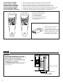
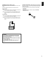
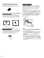
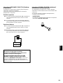
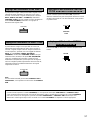
SUPPLIED ACCESSORIES
●
After unpacking, check that the following accessories are included.
ACCESSOIRES FOURNIS
●
Après le déballage, vérifier que les pièces suivantes sont incluses.
MITGELIEFERTES ZUBEHÖR
●
Nach dem Auspacken überprüfen, ob die folgenden Teile vorhanden sind.
MEDFÖLJANDE TILLBEHÖR
●
Kontrollera efter det apparaten packats upp att följande delar finns med.
ACCESSORI IN DOTAZIONE
●
Verificare che tutte le parti seguenti siano contenute nell’imballaggio dell’apparecchio.
ACCESORIOS INCLUIDOS
●
Desembale el aparato y verificar que los siguientes accesorios están en la caja.
BIJGELEVERDE ACCESSOIRES
●
Controleer na het uitpakken of de volgende onderdelen voorhanden zijn.
YAMAHA HiFi SYSTEM
REMOTE CONTROL TRANSMITTER
AUX
TAPE 2
TAPE 1
A/B
PLAY
REC/PAUSE
DIR A DIR B
CD
PHONO
PLAYDISC
POWER VOLUME
TUNER
A/B/C/D/EPRESET
YAMAHA HiFi SYSTEM
REMOTE CONTROL TRANSMITTER
AUX
TAPE 2
TAPE 1
A/B
PLAY
/CUT
PLAY
REC/PAUSE
DIR A DIR B
CD
PHONO
PLAYDISC
POWER VOLUME
TUNER
A/B/C/D/EPRESET
AX-592/892 AX-492
●
Batteries (size AA, R6, UM-3)
●
Piles (taille AA, R6, UM-3)
●
Batterien (Größe AA, R6, UM-3)
●
Batterier (storlek AA, R6, UM-3)
●
Batterie (dimensioni AA, R6, UM-3)
●
Pilas (tamaño AA, R6, UM-3)
●
Batterijen (maat AA, R6, UM-3)
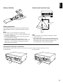
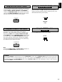
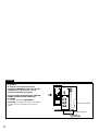
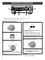
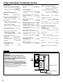
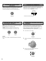
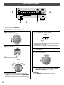
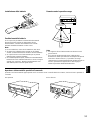
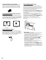
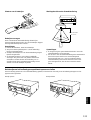
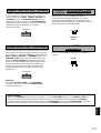
WARNING
Do not change the IMPEDANCE SELECTOR
switch setting while the power to this unit is on,
otherwise this unit may be damaged.
IF THIS UNIT FAILS TO TURN ON WHEN THE
POWER SWITCH IS PRESSED
The IMPEDANCE SELECTOR switch may not be
set to either end closely. If so, set the switch to
either end closely.
IMPEDANCE
SELECTOR
AC OUTLETS
SWITCHIED
100W MAX. TOTAL
A OR B : 4Ω MIN. /SPEAKER
A + B : 8Ω MIN. /SPEAKER
A OR B : 6Ω MIN. /SPEAKER
A + B :12Ω MIN. /SPEAKER
VOLTAGE SELECTOR
Example: AX-892
<General model>
English

English
3
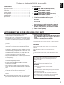
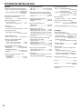
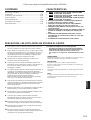
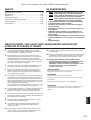
Supplied accessories .....................................................2
Connections ...................................................................4
Controls and their functions ..........................................10
Remote control .............................................................12
Basic operations ...........................................................14
Troubleshooting ............................................................18
Specifications ...............................................................19
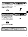
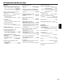
●
85W + 85W (8Ω) RMS Output Power,
0.019% THD, 20–20,000 Hz
●
100W + 100W (8Ω) RMS Output Power,
0.015% THD, 20–20,000 Hz
●
115W + 115W (8Ω) RMS Output Power,
0.015% THD, 20–20,000 Hz
●
High Dynamic Power, Low Impedance Drive Capability
●
Continuously Variable Loudness Control
●
CD DIRECT AMP switch: used to reproduce the purest
CD sound
●
PURE DIRECT switch: used to reproduce the purest
source sound
●
SUBSONIC FILTER switch; used to eliminate undesirable
ultra-low-frequency signals (
AX-592 and AX-892 only
)
●
PRE OUT/MAIN IN terminals; useful for connecting an
equalizer, sound processor, etc. (
AX-592 and AX-892
only
)
●
Remote control capability
AX-892
AX-592
AX-492
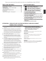
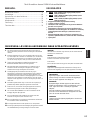
1. To assure the finest performance, please read this manual
carefully and keep it in a safe place for future use.
2. Install this unit in a cool, dry and dust-free area. Do not place it in
direct sunlight or near sources of heat (e.g., a stove, etc.). Make
sure that it is well ventilated and not exposed to rain or moisture
and that it is on a flat, stable surface, free from vibration.
3. Never open the cabinet. If something drops into the unit, contact
your dealer.
4. When moving the unit, first disconnect the AC power plug and the
cables which are connected to other equipment. Never pull the
cables or use excessive force on switches or controls.
5. The openings on the cabinet assure proper ventilation of the unit.
If these openings are obstructed, the temperature inside the
cabinet will rise rapidly, damaging the unit or causing a fire. Avoid
blocking the ventilation openings and make sure that the unit is
well ventilated. Allow at least 30 cm (12 in) of space above the
unit and 20 cm (8 in) of space on the sides and rear.
6. Always set the VOLUME control to “
∞
” before playing the source.
Increase the volume gradually to a desired level after the source
has started playing.
7. Use a clean, dry cloth to clean the unit. Do not use chemical
solvents which might damage the finish.
8. Be sure to read the “TROUBLESHOOTING” section before
deciding that the unit is faulty.
9. When not planning to use this unit for long periods of time (e.g.,
vacation, etc.), disconnect the AC power plug from the electrical
outlet.
10. To prevent damage from lightning, disconnect the AC power plug
and antenna cable when there is an electrical storm.
11. Make sure that the unit is always properly grounded and
polarized.
12. Do not connect audio equipment to the AC outlet on the rear panel
if the equipment requires more power than the outlet is rated to
provide.
13. Voltage Selector (General Model only)
The voltage selector on the rear panel of this unit must be set
for your local main voltage
before
plugging into the electrical
outlet.
Voltages are 110/120/220/240 V AC, 60/50 Hz.
WARNING
To reduce the risk of fire or electric shock, do not expose the unit to
rain or moisture.
IMPORTANT
The serial number is located on the rear panel.
Please record the serial number of this unit in the space below.
Serial No.:
Keep this Owner’s Manual in a safe place for future use.
Note
The unit is not disconnected from the AC power source as long as it
is connected to the electrical outlet, even if the unit itself is turned
off.
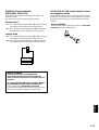
For UK customers
If the electrical outlets in the home are not suitable for the plug
which is supplied with this unit, cut off the plug and attach an
appropriate 3-pin plug.
Note
The removed plug must be destroyed, as a plug with exposed wires
is hazardous if inserted into a live electrical outlet.
IMPORTANT
The wires in the mains lead are colored as follows:
Blue: Neutral
Brown: Live
As the colors of the wires in the mains lead of this apparatus may
not correspond with the colored markings identifying the terminals in
your plug, proceed as follows:
The wire which is colored BLUE must be connected to the terminal
which is marked with the letter N or colored BLACK. The wire
which is colored BROWN must be connected to the terminal which
is marked with the letter L or colored RED. Make sure that neither
core is connected to the ground terminal of the 3-pin plug.
CAUTION: READ THIS BEFORE OPERATING YOUR UNIT.
Thank you for selecting this YAMAHA stereo amplifier.
CONTENTS FEATURES

4
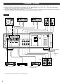
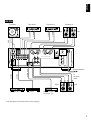
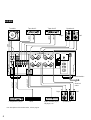
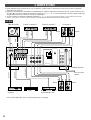
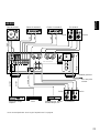
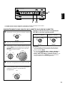
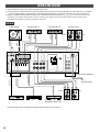
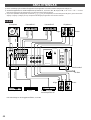
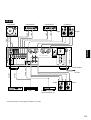
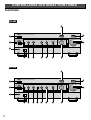
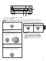
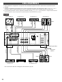
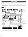
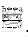
CONNECTIONS
●
Before making any connections to or from this unit, first switch it and any other connected components off.
●
Properly connect this unit and other components, L (left) to L, R (right) to R, “+” to “+” and “–” to “–”. Also, refer to the owner’s
manual of each component which is to be connected to this unit.
●
If you have YAMAHA components numbered 1, 2, 3, etc. on the rear panel, connections can easily be made by connecting the
output (input) terminals of each component to the same-numbered terminals on this unit.
CAUTION
SEE INSTRUCTION MANUAL FOR CONNECT SETTING
PHONO
CD
TUNER
R
L
R
L
1
2
TAPE 1
TAPE
PB
TAPE 2
(MD)
AUX
3
REC
OUT
4
TAPE
PB
3
REC
OUT
4
GND
SPEAKERS
AC OUTLETS
SWITCHIED
100W MAX. TOTAL
A
L
R
R L
B
VOLTAGE SELECTOR
IMPEDANCE SELECTOR
A OR B : 4Ω MIN. /SPEAKER
A + B : 8Ω MIN. /SPEAKER
A OR B : 6Ω MIN. /SPEAKER
A + B :12Ω MIN. /SPEAKER
+ – – +
+ – – +
OUTPUT
GND
OUTPUT
OUTPUT
AUDIO OUT
LINE OUT
LINE IN
LINE OUT
LINE IN
AX-492
Turntable Tape deck 1 Tape deck 2 Speakers A
Speakers B
Video cassette player,
LD player, etc.
TunerCompact disc player
Right Left
Right Left
<General model>
To
electrical
outlet
* For descriptions of the shaded areas, refer to page 8.

5
English
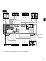
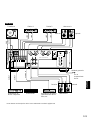
CAUTION
SEE INSTRUCTION MANUAL FOR CONNECT SETTING
PHONO
CD
TUNER
COUPLER
PRE
OUT
MAIN
IN
R
L
L
R
L
MM
MC
1
2
TAPE 1
TAPE
PB
TAPE 2
(MD)
AUX
3
REC
OUT
4
TAPE
PB
3
REC
OUT
4
REMOTE
CONTROL
PHONO
SPEAKERS IMPEDANCE
SELECTOR
AC OUTLETS
100W MAX. TOTAL
SWITCHIED
A OR B : 4Ω MIN. /SPEAKER
A + B : 8Ω MIN. /SPEAKER
A
B
R
L
R
R L
R L
A OR B : 6Ω MIN. /SPEAKER
A + B :12Ω MIN. /SPEAKER
GND
– + – +
+ – – +
OUTPUT
OUTPUT
AUDIO OUT
OUTPUT
LINE OUT
LINE IN
LINE OUT
LINE IN
GND
VOLTAGE SELECTOR
AX-592
<General model>
Turntable Tape deck 1 Tape deck 2 Speakers A
Speakers BVideo cassette player,
LD player, etc.
TunerCompact disc player
Right Left
Right
Left
To
electrical
outlet
* For descriptions of the shaded areas, refer to page 8.

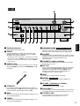
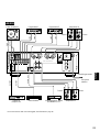
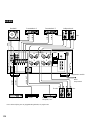
6
CAUTION
SEE INSTRUCTION MANUAL FOR CONNECT SETTING
PHONO
CD
TUNER
PRE
OUT
MAIN
IN
R
L
L
R
L
MM
MC
1
2
TAPE 1
TAPE
PB
TAPE 2
(MD)
AUX
3
REC
OUT
4
TAPE
PB
3
REC
OUT
4
GND
REMOTE
CONTROL
PHONO
SPEAKERS IMPEDANCE
SELECTOR
AC OUTLETS
SWITCHIED
100W MAX. TOTAL
A OR B : 4Ω MIN. /SPEAKER
A + B : 8Ω MIN. /SPEAKER
R
L
R
A OR B : 6Ω MIN. /SPEAKER
A + B :12Ω MIN. /SPEAKER
B
R L
A
R
L
COUPLER
– + – +
– + – +
LINE OUT
OUTPUT
OUTPUT
AUDIO OUT
OUTPUT
GND
LINE IN
LINE OUT
LINE IN
VOLTAGE SELECTOR
AX-892
Turntable Tape deck 1 Tape deck 2 Speakers A
Speakers BVideo cassette player,
LD player, etc.
TunerCompact disc player
Right Left
Right Left
To
electrical
outlet
* For descriptions of the shaded areas, refer to page 8.
<General model>

7
English
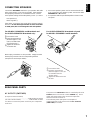
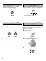
7
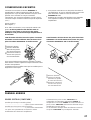
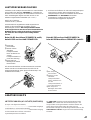
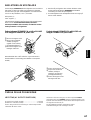
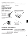
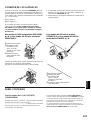
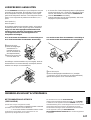
Connect the SPEAKERS terminals to your speakers with cable
of the proper gauge, cut as short as possible. If the speakers
are improperly connected, no sound will be heard. Connect
each speaker making sure that the polarity (+ and –) is correct.
Red: positive (+)
Black: negative (–)
If the cables are reversed, the sound will be unnatural and will
lack bass. Do not allow exposed wires to touch each other
or metal parts; this could damage the unit and speakers.
For AX-492’s SPEAKERS A and B terminals and
for AX-592’s SPEAKERS B terminals only:
➀
Unscrew the knob.
➁
Insert the exposed wire.
[Remove approx. 5 mm
(1/4 in) insulation from
the speaker wires.]
➂
Tighten the knob and
secure the wire.
Banana plug connections are also possible. Simply insert the
banana plug connector into the corresponding terminal.
(except for UK and Europe models)
●
One or two speaker systems can be connected to this unit.
If you connect only one speaker system, connect it to either
SPEAKERS A or B terminals.
●
Use speakers with the specified impedance shown on the
rear panel.
For AX-592’s SPEAKERS A terminals only and
for AX-892’s SPEAKERS A and B terminals:
CONNECTING SPEAKERS
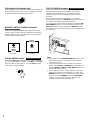
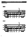
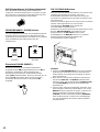
REAR PANEL PARTS
1
2
3
2
3
1
AC OUTLETS (SWITCHED)
(Europe and General models)
............................................................3 SWITCHED OUTLETS
(UK and Australia models) ....................1 SWITCHED OUTLET
Use these to connect the power cords from your components
to this unit.
The power to the SWITCHED outlets is controlled by this unit’s
POWER switch or the remote control’s POWER key. These
outlets will supply power to the connected components
whenever this unit is turned on.
The maximum power (total power consumption of
components) that can be connected to the AC OUTLETS
(SWITCHED) is 100 watts.
➀
Unscrew the knob.
➁
Insert the exposed wire.
[Remove approx. 5 mm (1/4
in) insulation from the
speaker wires.]
➂
Tighten the knob and secure
the wire.

8
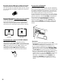
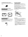
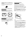
GND terminal (for turntable use)
Connecting the ground wire of the turntable to this terminal will
normally minimize hum, but in some cases better results may
be obtained with the ground wire disconnected.
COUPLER
PRE
OUT
MAIN
IN
L
R
MM
MC
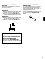
REMOTE CONTROL (PHONO) connector
If you have a YAMAHA turntable with a terminal for remote
control, connect it to this connector using the cable provided
with the turntable. This connection allows you to control the
turntable with the remote control.
AX-592 and AX-892 only
REMOTE
CONTROL
PHONO
REMOTE
CONTROL
PHONO
PHONO (MM/MC) switch
Select either MM or MC depending on your phono cartridge. If
you use a high-output MC cartridge, select MM. To select MC,
press the switch so that it stays in. To select MM, press the
switch again, so that it releases.
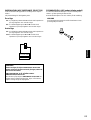
PRE OUT/MAIN IN terminals
Removing the jumper pins enables this unit to independently
perform the functions of a control amplifier and a power
amplifier. These terminals are for connection of a signal-
processing system such as a graphic equalizer or sound
processor.
If a sound processor or other external unit is connected
between these terminals, the VOLUME control of this unit can
be used for overall adjustment of the sound level.
To connect such a unit, remove the jumper pins from the PRE
OUT/MAIN IN terminals, connect the inputs of that unit to the
PRE OUT terminals and its outputs to the MAIN IN terminals.
For details, refer to the owner’s manual included with the unit to
be connected.
AX-592 and AX-892 only
Note
●
If you will not use the PRE OUT/MAIN IN terminals, never
remove the jumper pins. If removed, no sound will be
output from this unit.
●
If you will use this unit with an external unit connected
between the PRE OUT and MAIN IN terminals, make sure
that the CD DIRECT AMP and PURE DIRECT switches on
the front panel are turned off.
●
If you will use this unit as a power amplifier, connect the
outputs of an external control amplifier, etc. to this unit’s
MAIN IN terminals. In this case, this unit’s controls will not
function, except the PHONES jack and the SPEAKERS
switches, so use the controls on the external control
amplifier to make volume adjustment, etc.
AX-592 and AX-892 only
(AX-592)
(AX-892)

9
English
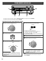
WARNING
Do not change the IMPEDANCE SELECTOR switch
setting while the power to this unit is on, otherwise
this unit may be damaged.
IF THIS UNIT FAILS TO TURN ON WHEN THE POWER
SWITCH IS PRESSED
The IMPEDANCE SELECTOR switch may not be set to
either end closely. If so, set the switch to either end
closely.
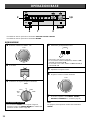
IMPEDANCE SELECTOR switch
Make sure that the power to the unit is off, before you set the
switch.
Select the appropriate setting for your speaker system.
Upper position
4 Ω: If you use either speaker system A or B, the impedance
of each speaker must be 4 Ω, or higher.
8 Ω: If you use both speaker systems A and B at the same
time, the impedance of each speaker must be 8 Ω, or
higher.
Lower position
6 Ω: If you use either speaker system A or B, the impedance
of each speaker must be 6 Ω, or higher.
12 Ω:If you use both speaker systems A and B at the same
time, the impedance of each speaker must be 12 Ω, or
higher.
A OR B : 4Ω MIN. /SPEAKER
A + B : 8Ω MIN. /SPEAKER
A OR B : 6Ω MIN. /SPEAKER
A + B :12Ω MIN. /SPEAKER
VOLTAGE SELECTOR switch (General model only)
If the pre-set setting is incorrect, set the switch to the proper
voltage for your area.
Consult your dealer if you are unsure of the correct setting.
WARNING
Be sure to unplug the unit before setting the VOLTAGE
SELECTOR switch.

10
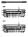
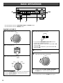
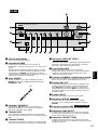
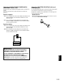
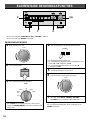
CONTROLS AND THEIR FUNCTIONS
FRONT PANEL
NATURAL SOUND STEREO AMPLIFIER AX-492
PHONES
INPUT VOLUME
CD DIRECT AMP PURE DIRECT
POWER
SPEAKERS
A
ON OFF
B
BASS
1
2
3
4
– 5
1
2
3
4
5 +
0
LOUDNESS
1
2
3
4
5
-30db
10
9
8
7
FLAT
6
BALANCE
1
2
3
4
L 5
1
2
3
4
5 R
0
TREBLE
1
2
3
4
– 5
1
2
3
4
5 +
0
REC OUT
CD
TUNER
PHONO
TAPE 1
TAPE 2
(MD)
AUX
PHONO
TUNER
TAPE 2
(MD)
AUX
TAPE 1
CD
-db
16
0
∞
260
440
828
1220
2
3
1
E
D
C
A09865
4
NATURAL SOUND STEREO AMPLIFIER AX-592
PHONES
CD DIRECT AMP
SPEAKERS
A
ON OFF
B
POWER
INPUT VOLUME
PURE DIRECT
BASS
1
2
3
4
– 5
1
2
3
4
5 +
0
LOUDNESS
1
2
3
4
5
-30db
10
9
8
7
FLAT
6
BALANCE
1
2
3
4
L 5
1
2
3
4
5 R
0
TREBLE
1
2
3
4
– 5
1
2
3
4
5 +
0
REC OUT
CD
TUNER
PHONO
TAPE 1
TAPE 2
(MD)
AUX
PHONO
TUNER
TAPE 2
(MD)
AUX
TAPE 1
CD
-db
16
0
∞
260
440
828
1220
SUBSONIC
FILTER
ON OFF
2
3
1
E
D
A0986
754
C
AX-492
AX-592

11
English
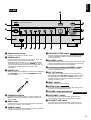
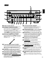
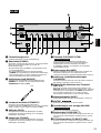
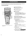
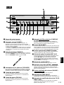
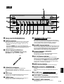
1 Remote control sensor
Receives signals from the remote control.
2 POWER switch
Press this switch to turn the power on and off. When the
power is on, the indicator will be illuminated.
*Standby mode <Except for U.S.A. and Canada models>
While the power is on, pressing the POWER key on the
remote control switches the unit to the standby mode. (In
this mode, the power indicator on the unit is half-
illuminated.)
3 PHONES jack
When you listen with headphones, connect the headphones
to the PHONES jack and set both SPEAKERS A and B
switches to OFF.
4 SPEAKERS switches
For the desired speaker system(s), set the switch(es) to
ON. When using only one speaker system, set the other
switch to OFF.
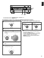
5 BASS control
Used to increase or decrease the low-frequency response.
Selecting “0” produces a flat response.
6 TREBLE control
Used to increase or decrease the high-frequency response.
Selecting “0” produces a flat response.
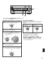
7 SUBSONIC FILTER switch
Used to eliminate undesirable ultra-low-frequency signals
caused by turntable rumble or warped records without
losing sound quality.
8 BALANCE control
Adjusts the balance of the output volume to the left and right
speakers to compensate for channel imbalance caused by
speaker location or listening room conditions.
9 Continuously variable LOUDNESS control
Used to boost high and low-frequency ranges at low
volume. (Refer to page 16.)
0 REC OUT selector
This switch can be used to select a source and send its
signal directly to the REC OUT terminals on the rear panel,
independently of the setting of the INPUT selector. This
function allows you to record the selected source while
listening to another source.
A INPUT selector
Selects an input source to listen to.
B MUTING switch
Press this switch to temporarily reduce the volume. Press
again to cancel the MUTING function.
C VOLUME control and indicator
Used to raise or lower the volume level.
D PURE DIRECT switch
Press this switch (the indicator lights up) to listen to a
source in the purest possible sound. (Refer to page 17.)
E CD DIRECT AMP switch
Press this switch (the indicator lights up) to listen in the
purest possible sound from your CD. (Refer to page 17.)
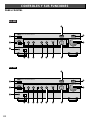
NATURAL SOUND STEREO AMPLIFIER AX-892
PHONES
INPUT VOLUME
CD DIRECT AMP PURE DIRECT
SPEAKERS
A
ON OFF
B
POWER
SUBSONIC
FILTER
ON OFF
MUTING
ON OFF
BASS
1
2
3
4
– 5
1
2
3
4
5 +
0
LOUDNESS
1
2
3
4
5
-30db
10
9
8
7
FLAT
6
BALANCE
1
2
3
4
L 5
1
2
3
4
5 R
0
TREBLE
1
2
3
4
– 5
1
2
3
4
5 +
0
REC OUT
CD
TUNER
PHONO
TAPE 1
TAPE 2
(MD)
AUX
PHONO
TUNER
TAPE 2
(MD)
AUX
TAPE 1
CD
-db
16
0
∞
260
440
828
1220
2
3
1
E
D
B
A0986
754
C
AX-892 only
AX-592 and AX-892 only
AX-592 and AX-892 only
PHONES
AX-892

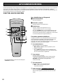
12
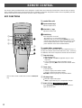
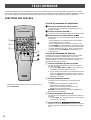
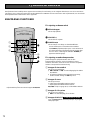
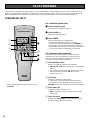
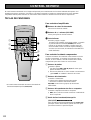
The remote control provided with this unit is designed to control all the most commonly used functions of the unit. If the CD player,
tuner, turntable and tape deck connected to this unit are YAMAHA components designed for remote control compatibility, then this
remote control will also control the various functions of those components.
KEY FUNCTIONS
YAMAHA HiFi SYSTEM
REMOTE CONTROL TRANSMITTER
AUX
TAPE 2
TAPE 1
A/B
PLAY
REC/PAUSE
DIR A DIR B
CD
PHONO
PLAY
/CUT
PLAYDISC
TUNER
A/B/C/D/EPRESET
POWER VOLUME
To control this unit
1 Input selector keys
Select an input source.
2 VOLUME +/– keys
Adjust the volume level.
3 POWER key
Turns the power on and off.
<Except for U.S.A. and Canada models>
While the power is on, pressing the POWER key on the
remote control switches the unit from the power-on mode
to the standby mode and vice versa. (In this mode, the
power indicator on the unit is half-illuminated.)
To control other components
Identify the remote control keys with your component’s keys. If
the keys are identical, the functions will be the same. If the keys
are different, refer to the component’s manual for their functions.
1 Tape deck keys
Control the tape deck.
●
DIR A, DIR B, and A/B are applicable only for a dual
tape deck.
●
For a single tape deck with an automatic reverse
function, pressing DIR A will reverse the direction of the
tape.
2 Tuner keys
Control the tuner.
+: Selects a higher preset station number.
–: Selects a lower preset station number.
A/B/C/D/E: Selects a group (A-E) of preset stations.
3 CD player keys
Control the compact disc player.
●
DISC is applicable only for a compact disc changer.
4 PLAY/CUT key
Press PLAY/CUT to lower the pick-up arm and press it
again to raise the arm.
1
4
2
3
1
2
3
* The AX-492’s remote control does not have a PLAY/CUT
key.
AX-592 and AX-892 only
REMOTE CONTROL

13
English
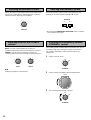
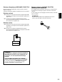
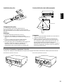
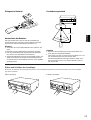
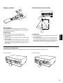
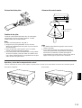
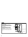
To open the door To close the door
Battery installation
Battery replacement
If you find that the remote control must be used closer to the
unit, the batteries are weak. Replace both batteries with new
ones.
Note
●
Use only AA, R6, UM-3 batteries for replacement.
●
Be sure the polarities are correct. (See the illustration inside
the battery compartment.)
●
Remove the batteries if the remote control will not be used
for an extended period of time.
●
If batteries leak, dispose of them immediately. Avoid
touching the leaked material or letting it come in contact with
clothing, etc. Clean the battery compartment thoroughly
before installing new batteries.
Remote control operation range
Note
●
There should be no large obstacles between the remote
control and the unit.
●
If the remote control sensor is directly illuminated by strong
lighting (especially an inverter type of fluorescent lamp etc.),
it might prevent the remote control from working. In this
case, reposition the unit to avoid direct lighting.
2
3
1
30°
30°
Remote control
sensor
Within approximately
6 m (19.7 feet)
Opening and closing the control door
When using the remote control or when it is not necessary to operate controls inside the control door, close it.

14
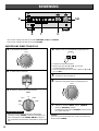
PLAYING A SOURCE
VOLUME
-db
16
0
∞
260
440
828
1220
POWER
INPUT
PHONO
TUNER
TAPE 2
(MD)
AUX
TAPE 1
CD
SPEAKERS
A
ON OFF
B
NATURAL SOUND STEREO AMPLIFIER AX-892
PHONES
INPUT VOLUME
CD DIRECT AMP PURE DIRECT
SPEAKERS
A
ON OFF
B
POWER
SUBSONIC
FILTER
ON OFF
MUTING
ON OFF
BASS
1
2
3
4
– 5
1
2
3
4
5 +
0
LOUDNESS
1
2
3
4
5
-30db
10
9
8
7
FLAT
6
BALANCE
1
2
3
4
L 5
1
2
3
4
5 R
0
TREBLE
1
2
3
4
– 5
1
2
3
4
5 +
0
REC OUT
CD
TUNER
PHONO
TAPE 1
TAPE 2
(MD)
AUX
PHONO
TUNER
TAPE 2
(MD)
AUX
TAPE 1
CD
-db
16
0
∞
260
440
828
1220
4 7 3
2
1,6
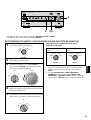
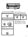
7 If needed, adjust the BASS, TREBLE, BALANCE
LOUDNESS, etc. controls. (Refer to page 16.)
1 Turn the control to “∞”.
4 Select the speakers to be used.
* Be sure that the IMPEDANCE SELECTOR switch is
correctly set as explained on page 9.
* If you use two speaker systems, press both the A and B
switches to ON.
* If you listen with headphones, press both the A and B
switches to OFF.
5 Play the source.
6 Adjust the volume to the desired level.
2 Turn the power on.
3 Select the desired input source.
* If you select PHONO as an input source, you should make
sure that PHONO (MM/MC) is switched to the correct
position. (Refer to page 8.)
Note
To turn off the power, press the POWER switch again.
AX-592 and AX-892 only
* The AX-492 does not have a SUBSONIC FILTER and MUTING switch.
* The AX-592 does not have a MUTING switch.
VOLUME
-db
16
0
∞
260
440
828
1220
(AX-892)
BASIC OPERATIONS

15
English
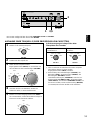
RECORDING A SOURCE TO A TAPE (OR DUBBING FROM TAPE TO TAPE)
REC OUT selector setting for dubbing tape to tape
INPUT
VOLUME
-db
16
0
∞
260
440
828
1220
PHONO
TUNER
TAPE 2
(MD)
AUX
TAPE 1
CD
INPUT
PHONO
TUNER
TAPE 2
(MD)
AUX
TAPE 1
CD
To tape from tape deck 1 to
tape deck 2.
To tape from tape deck 2 to
tape deck 1.
Note
●
If you want to listen to another source while recording,
select it with the INPUT selector.
●
VOLUME, BASS, TREBLE, BALANCE, and LOUDNESS
controls and CD DIRECT AMP, PURE DIRECT,
SUBSONIC FILTER (
AX-592 and AX-892 only
) and the
MUTING switch (
AX-892 only
) have no effect on the
material being recorded.
1 Select the source to be recorded.
2 Play the source.
3 Select the source with the INPUT selector and use the
VOLUME control to make sure that the proper source
is selected.
4 Set the tape deck used for recording in the recording
mode.
5 To monitor the sound of the recording, select the tape
deck being used for recording.
REC OUT
CD
TUNER
PHONO
TAPE 1
TAPE 2
(MD)
AUX
REC OUT
CD
TUNER
PHONO
TAPE 1
TAPE 2
(MD)
AUX
REC OUT
CD
TUNER
PHONO
TAPE 1
TAPE 2
(MD)
AUX
NATURAL SOUND STEREO AMPLIFIER AX-892
PHONES
INPUT VOLUME
CD DIRECT AMP PURE DIRECT
SPEAKERS
A
ON OFF
B
POWER
SUBSONIC
FILTER
ON OFF
MUTING
ON OFF
BASS
1
2
3
4
– 5
1
2
3
4
5 +
0
LOUDNESS
1
2
3
4
5
-30db
10
9
8
7
FLAT
6
BALANCE
1
2
3
4
L 5
1
2
3
4
5 R
0
TREBLE
1
2
3
4
– 5
1
2
3
4
5 +
0
REC OUT
CD
TUNER
PHONO
TAPE 1
TAPE 2
(MD)
AUX
PHONO
TUNER
TAPE 2
(MD)
AUX
TAPE 1
CD
-db
16
0
∞
260
440
828
1220
3,51
3
* The AX-492 does not have a SUBSONIC FILTER and MUTING switch.
* The AX-592 does not have a MUTING switch.
(AX-892)

16
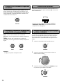
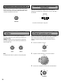
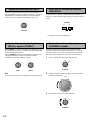
Adjusting the BASS and TREBLE
controls
Adjusting the BALANCE control Selecting the SPEAKER system
Adjusts the balance of the output volume to the left and right
speakers to compensate for channel imbalance caused by
speaker location or listening room conditions.
One or two speaker systems can be connected to this unit,
allowing you to select speaker system A or B, or both.
Adjusting the continuously variable
LOUDNESS control
This control provides compensation for the human ears’ loss of
sensitivity to high and low-frequency ranges at low volume.
This control is adjustable to retain full tonal range at any
volume level.
1 Set the control to “FLAT”.
2 Set the volume to the highest desired listening level.
3 Turn until the desired volume is gained.
BALANCE
1
2
3
4
L 5
1
2
3
4
5 R
0
BASS
1
2
3
4
– 5
1
2
3
4
5 +
0
TREBLE
1
2
3
4
– 5
1
2
3
4
5 +
0
SPEAKERS
A
ON OFF
B
VOLUME
-db
16
0
∞
260
440
828
1220
LOUDNESS
1
2
3
4
5
-30db
10
9
8
7
FLAT
6
BASS: Turn this control clockwise to increase (or
counterclockwise to decrease) the low-frequency response.
TREBLE: Turn this control clockwise to increase (or
counterclockwise to decrease) the high-frequency response.
LOUDNESS
1
2
3
4
5
-30db
10
9
8
7
FLAT
6
Note
Selecting “0” produces a flat response.
* Be sure that the INPEDANCE SELECTOR switch is correctly
set as explained on page 9.

17
English
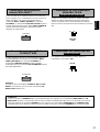
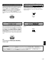
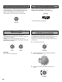
Setting the SUBSONIC FILTER switch
Using the PURE DIRECT switch
You can enjoy the purest possible sound from your sources by
setting this switch so that the indicator illuminates. The signals
bypass the BASS, TREBLE, BALANCE and LOUDNESS
controls, the SUBSONIC FILTER switch (
AX-592 and AX-892
only
), and the PRE OUT/MAIN IN terminals (
AX-592 and AX-
892 only
), eliminating any alterations to the signals.
Selecting ON temporarily reduces the volume.
When this switch is set ON, undesirable ultra-low-frequency
signals caused by turntable rumble or warped records can be
eliminated without losing sound quality.
MUTING
ON OFF
PURE DIRECT
SUBSONIC
FILTER
ON OFF
Using the CD DIRECT AMP switch
For the best CD sound, set this switch so the indicator
illuminates. The CD input signal is sent to a separate circuit,
bypassing the INPUT selector, BASS, TREBLE, BALANCE
and LOUDNESS controls, SUBSONIC FILTER switch (AX-592
and AX-892 only), and the PRE OUT/MAIN IN terminals (
AX-
592 and AX-892 only
) and then goes directly to the amplifier.
This signal routing ensures the purest CD sound, eliminating
any alterations to the original CD signals.
CD DIRECT AMP
Using the MUTING switch
Note
If both the CD DIRECT AMP and PURE DIRECT switches are
on, only the CD DIRECT AMP switch will function.
AX-592 and AX-892 only
AX-892 only
WARNING
When the LOUDNESS control has been set, if the PURE DIRECT switch or the CD DIRECT AMP switch is pressed, the sound
will suddenly increase and may damage your ears or the speaker (the LOUDNESS control function may be bypassed).
Therefore, only press the PURE DIRECT switch or the CD DIRECT AMP switch after lowering the volume or after checking
that the LOUDNESS control is properly set.

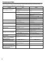
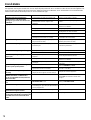
18
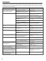
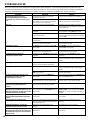
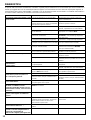
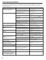
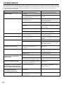
SYMPTOM
The unit fails to turn on when the POWER
switch is pressed, or turns off suddenly
soon after the power is turned on.
No sound.
Sound level is too low.
The sound suddenly goes off.
Only one speaker outputs sound.
There is a lack of bass and no ambience.
The sound “hums”.
Sound level is low or sound is distorted
while playing a record on the turntable.
The volume level cannot be increased, or
sound is distorted.
Using the BASS, TREBLE, BALANCE, and
LOUDNESS controls and SUBSONIC
FILTER switch (
AX-592 and AX-892 only
)
does not affect the tone.
The input source can not be changed,
though the INPUT selector is turned.
The remote control does not work.
The distance or range within which the
remote control can be used decreases.
The sound is degraded when listening with
the headphones connected to the compact
disc player or cassette deck that are
connected with this unit.
CAUSE
The AC power plug is not plugged in or is not
completely inserted.
The IMPEDANCE SELECTOR switch on the
rear panel is not set to the upper or the lower
end exactly.
Incorrect output cable connections.
The appropriate input source is not selected.
The SPEAKERS switches are not set
properly.
Speaker connections are not secure.
The jumpor pins (PRE OUT/MAIN IN) are not
connected properly. (AX-592 and AX-892 only)
The MUTING switch is pushed in. (Muting is
on) (AX-892 only)
The protection circuit has been activated
because of a short circuit, etc.
Incorrect setting of the BALANCE control.
Incorrect cable connections.
The cable polarity is reversed at the amplifier
or speakers.
Incorrect cable connections.
No connection from the turntable to the GND
terminal.
The LOUDNESS control is functioning.
The PHONO (MM/MC) switch is set to the
improper position (
AX-592 and AX-892 only
).
The power to the component connected to the
REC OUT terminals of this unit is off.
The CD DIRECT AMP or PURE DIRECT
switch is on.
The CD DIRECT AMP switch is on.
Direct sunlight or lighting (of an inverter type of
fluorescent lamp etc.) is striking the remote
control sensor of the unit.
The batteries of the remote control are too
weak.
The power to this unit is off.
REMEDY
Firmly plug in the AC power plug.
Set the switch to the upper or the lower end
exactly.
Connect the cables properly. If the problem
persists, the cables may be defective.
Select an appropriate input source with the
INPUT selector.
Set the SPEAKERS switch, which corresponds
to the speakers to be used, to ON.
Secure the connections.
Connect the jumper pins properly.
(AX-592 and AX-892 only)
Push the MUTING switch again. (Muting is off)
(AX-892 only)
Turning the unit off and then on will reset the
protection circuit.
Adjust it to the appropriate position.
Connect the cables properly. If the problem
persists, the cables may be defective.
Connect the speaker cables correctly.
Firmly connect the cables. If the problem
persists, the cables may be defective.
Make the GND connection between the
turntable and this unit.
Set the LOUDNESS control to the FLAT
position.
Set the PHONO (MM/MC) switch to the proper
position (
AX-592 and AX-892 only
).
Turn the power to the component on.
The CD DIRECT AMP and PURE DIRECT
switches must be switched off to use those
controls.
Switch off the CD DIRECT AMP switch.
Change the position of the unit.
Replace the batteries with new ones.
Turn the power to this unit on.
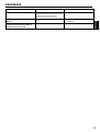
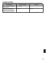
If the unit fails to operate normally, check the following points to determine whether the fault can be corrected by the simple
measures suggested. If it cannot be corrected, or if the fault is not listed in the SYMPTOM column, disconnect the AC power plug
and contact your authorized YAMAHA dealer or service center for help.
TROUBLESHOOTING

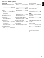
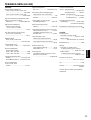
19
English
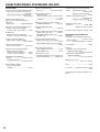
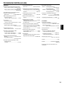
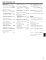
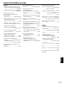
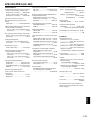
SPECIFICATIONS (AX-492)
AUDIO SECTION
Minimum RMS Output Power per Channel
8 ohms, 20 Hz to 20 kHz, 0.019% THD
...................................................85W+85W
6 ohms, 20 Hz to 20 kHz, 0.038% THD
...............................................100W+100W
Dynamic Power per Channel
(by IHF Dynamic Headroom measuring
method)
8/6/4/2 ohms...................130/150/185/220W
DIN Standard Output Power per Channel
[Europe model only]
(4 ohms, 1 kHz, 0.7% THD)..............120W
IEC Power [Europe model only]
(8 ohms, 1 kHz, 0.019% THD).............100W
Power Band Width
8 ohms, 42.5W, 0.038% THD
.............................................10 Hz to 50 kHz
Damping Factor SP-A
8 ohms, 20 Hz–20 kHz ..............240 or more
Maximum Output Power (EIAJ)
[General model only]
8 ohms, 1 kHz, 10% THD .................130W
6 ohms, 1 kHz, 10% THD .................150W
Input Sensitivity/Impedance
PHONO............................2.5 mV/47 k-ohms
CD/TUNER/TAPE/AUX
....150 mV/47 k-ohms
Maximum Input Signal (1 kHz, 0.003% THD)
PHONO.............................................115 mV
Output Level/Impedance
REC OUT.......................150 mV/0.6 k-ohms
Headphone Jack Rated Output/ Impedance
Output Level (8 ohms, 0.019% THD)
...............................................................0.3V
Impedance.....................................680 ohms
Frequency Response (20 Hz to 20 kHz)
CD/TUNER/TAPE/AUX
....................0±0.5 dB
RIAA Equalization Deviation
PHONO...........................................0±0.3 dB
Total Harmonic Distortion (20 Hz to 20 kHz)
PHONO to REC OUT (3V)................0.003%
CD/TUNER/TAPE/AUX
to SP OUT
(42.5W/8 ohms) ................................0.008%
Signal-to-Noise Ratio (IHF-A Network)
PHONO (5 mV Input Shorted) ............ 88 dB
CD (CD DIRECT AMP ON, Shorted)
... 110 dB
Residual Noise (IHF-A Network)
CD (CD DIRECT AMP ON)
...................35 µV
PURE DIRECT ON..............................90 µV
Channel Separation
CD/TUNER/TAPE/AUX
(Input 5.1 k-ohms
Terminated 1 kHz/10 kHz).........65 dB/50 dB
Tone Control Characteristics
BASS: Boost/cut................±10 dB (20 Hz)
Turnover Frequency.........(350 Hz)
TREBLE: Boost/cut...........±10 dB (20 kHz)
Turnover Frequency.....(3.5 kHz)
Continuous Loudness Control
Attenuation............................–30 dB (1 kHz)
(Level related equalization)
Gain Tracking Error (0 to –60 dB)............2 dB
GENERAL
Power Supply
[Europe and U.K. models] ...AC 230V, 50 Hz
[General model]
..................AC 110/120/220/240V, 60/50 Hz
Power Consumption...............................210W
AC Outlets
[Europe and General models]
3 SWITCHED OUTLETS..100W max. total
[U.K. model]
1 SWITCHED OUTLET ....100W max. total
Dimensions (W x H x D)
......................................435 x 151 x 391 mm
(17-1/8” x 6.0” x 15-3/8”)
Weight.............................9.6 kg (21 lbs. 1 oz.)
Accessories...........Remote control transmitter
Batteries
Specifications subject to change without
notice.

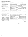
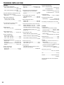
20
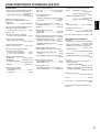
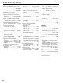
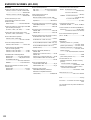
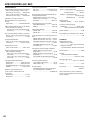
SPECIFICATIONS (AX-592)
AUDIO SECTION
Minimum RMS Output Power per Channel
8 ohms, 20 Hz to 20 kHz, 0.015% THD
...............................................100W+100W
6 ohms, 20 Hz to 20 kHz, 0.03% THD
...............................................120W+120W
Dynamic Power per Channel
(by IHF Dynamic Headroom measuring
method)
8/6/4/2 ohms...................140/170/220/290W
DIN Standard Output Power per Channel
[Europe model only]
(4 ohms, 1 kHz, 0.7% THD)..............155W
IEC Power [Europe model only]
(8 ohms, 1 kHz, 0.015% THD).............110W
Power Band Width
8 ohms, 50W, 0.03% THD
.............................................10 Hz to 50 kHz
Damping Factor SP-A
8 ohms, 20 Hz–20 kHz ..............320 or more
Maximum Output Power (EIAJ)
[General model only]
8 ohms, 1 kHz, 10% THD .................145W
6 ohms, 1 kHz, 10% THD .................170W
Input Sensitivity/Impedance
PHONO MM.....................2.5 mV/47 k-ohms
PHONO MC ......................160 µV/250 ohms
CD/TUNER/TAPE/AUX
....150 mV/47 k-ohms
MAIN IN .................................1 V/30 k-ohms
Maximum Input Signal (1 kHz, 0.007% THD)
PHONO MM......................................150 mV
PHONO MC........................................10 mV
Output Level/Impedance
REC OUT.......................150 mV/0.6 k-ohms
PRE OUT..............................1 V/1.2 k-ohms
Headphone Jack Rated Output/ Impedance
Output Level (8 ohms, 0.015% THD)
.............................................................0.33V
Impedance.....................................680 ohms
Frequency Response (20 Hz to 20 kHz)
CD/TUNER/TAPE/AUX
....................0±0.5 dB
MAIN IN
...........................................0±0.5 dB
RIAA Equalization Deviation
PHONO MM....................................0±0.3 dB
PHONO MC....................................0±0.5 dB
Total Harmonic Distortion (20 Hz to 20 kHz)
PHONO MM to REC OUT (3V).........0.003%
PHONO MC to REC OUT (3V) .........0.007%
CD/TUNER/TAPE/AUX
to PRE OUT (1 V)
..........................................................0.005%
CD/TUNER/TAPE/AUX to SP OUT
(50W/8 ohms) ...................................0.008%
Signal-to-Noise Ratio (IHF-A Network)
PHONO MM (5 mV Input Shorted) ..... 92 dB
PHONO MC (500 µV Input Shorted)... 76 dB
CD (CD DIRECT AMP ON Shorted)
... 110 dB
Residual Noise (IHF-A Network)
CD (CD DIRECT AMP ON)
...................35 µV
PURE DIRECT ON............................. 90 µV
Channel Separation
CD/TUNER/TAPE/AUX
(Input 5.1 k-ohms
Terminated 1 kHz/10 kHz).........65 dB/50 dB
Tone Control Characteristics
BASS: Boost/cut................±10 dB (20 Hz)
Turnover Frequency.........(350 Hz)
TREBLE: Boost/cut...........±10 dB (20 kHz)
Turnover Frequency.....(3.5 kHz)
Filter Characterristics
SUBSONIC FILTER .........15 Hz, –18 dB/oct
Continuous Loudness Control
Attenuation............................–30 dB (1 kHz)
(Level related equalization)
Gain Tracking Error (0 to –60 dB)............2 dB
GENERAL
Power Supply
[U.S.A. and Canada models]
...........................................AC 120 V, 60 Hz
[Australia model].................AC 240 V, 50 Hz
[Europe and U.K. models] ..AC 230 V, 50 Hz
[General model]
..................AC 110/120/220/240V, 60/50 Hz
Power Consumption...............................220W
[U.S.A model only]...............................200W
AC Outlets
[U.S.A., Europe, Canada and General models]
3 SWITCHED OUTLETS..100W max. total
[Australia and U.K. models]
1 SWITCHED OUTLET ....100W max. total
Dimensions (W x H x D)
......................................435 x 151 x 396 mm
(17-1/8” x 6.0” x 15-1/2”)
Weight...........................10.6 kg (23 lbs. 4 oz.)
Accessories...........Remote control transmitter
Batteries
Specifications subject to change without
notice.
Pagina se încarcă...
Pagina se încarcă...
Pagina se încarcă...
Pagina se încarcă...
Pagina se încarcă...
Pagina se încarcă...
Pagina se încarcă...
Pagina se încarcă...
Pagina se încarcă...
Pagina se încarcă...
Pagina se încarcă...
Pagina se încarcă...
Pagina se încarcă...
Pagina se încarcă...
Pagina se încarcă...
Pagina se încarcă...
Pagina se încarcă...
Pagina se încarcă...
Pagina se încarcă...
Pagina se încarcă...
Pagina se încarcă...
Pagina se încarcă...
Pagina se încarcă...
Pagina se încarcă...
Pagina se încarcă...
Pagina se încarcă...
Pagina se încarcă...
Pagina se încarcă...
Pagina se încarcă...
Pagina se încarcă...
Pagina se încarcă...
Pagina se încarcă...
Pagina se încarcă...
Pagina se încarcă...
Pagina se încarcă...
Pagina se încarcă...
Pagina se încarcă...
Pagina se încarcă...
Pagina se încarcă...
Pagina se încarcă...
Pagina se încarcă...
Pagina se încarcă...
Pagina se încarcă...
Pagina se încarcă...
Pagina se încarcă...
Pagina se încarcă...
Pagina se încarcă...
Pagina se încarcă...
Pagina se încarcă...
Pagina se încarcă...
Pagina se încarcă...
Pagina se încarcă...
Pagina se încarcă...
Pagina se încarcă...
Pagina se încarcă...
Pagina se încarcă...
Pagina se încarcă...
Pagina se încarcă...
Pagina se încarcă...
Pagina se încarcă...
Pagina se încarcă...
Pagina se încarcă...
Pagina se încarcă...
Pagina se încarcă...
Pagina se încarcă...
Pagina se încarcă...
Pagina se încarcă...
Pagina se încarcă...
Pagina se încarcă...
Pagina se încarcă...
Pagina se încarcă...
Pagina se încarcă...
Pagina se încarcă...
Pagina se încarcă...
Pagina se încarcă...
Pagina se încarcă...
Pagina se încarcă...
Pagina se încarcă...
Pagina se încarcă...
Pagina se încarcă...
Pagina se încarcă...
Pagina se încarcă...
Pagina se încarcă...
Pagina se încarcă...
Pagina se încarcă...
Pagina se încarcă...
Pagina se încarcă...
Pagina se încarcă...
Pagina se încarcă...
Pagina se încarcă...
Pagina se încarcă...
Pagina se încarcă...
Pagina se încarcă...
Pagina se încarcă...
Pagina se încarcă...
Pagina se încarcă...
Pagina se încarcă...
Pagina se încarcă...
Pagina se încarcă...
Pagina se încarcă...
Pagina se încarcă...
Pagina se încarcă...
Pagina se încarcă...
Pagina se încarcă...
Pagina se încarcă...
Pagina se încarcă...
Pagina se încarcă...
Pagina se încarcă...
Pagina se încarcă...
Pagina se încarcă...
Pagina se încarcă...
Pagina se încarcă...
Pagina se încarcă...
Pagina se încarcă...
Pagina se încarcă...
Pagina se încarcă...
Pagina se încarcă...
Pagina se încarcă...
Pagina se încarcă...
Pagina se încarcă...
Pagina se încarcă...
Pagina se încarcă...
Pagina se încarcă...
-
 1
1
-
 2
2
-
 3
3
-
 4
4
-
 5
5
-
 6
6
-
 7
7
-
 8
8
-
 9
9
-
 10
10
-
 11
11
-
 12
12
-
 13
13
-
 14
14
-
 15
15
-
 16
16
-
 17
17
-
 18
18
-
 19
19
-
 20
20
-
 21
21
-
 22
22
-
 23
23
-
 24
24
-
 25
25
-
 26
26
-
 27
27
-
 28
28
-
 29
29
-
 30
30
-
 31
31
-
 32
32
-
 33
33
-
 34
34
-
 35
35
-
 36
36
-
 37
37
-
 38
38
-
 39
39
-
 40
40
-
 41
41
-
 42
42
-
 43
43
-
 44
44
-
 45
45
-
 46
46
-
 47
47
-
 48
48
-
 49
49
-
 50
50
-
 51
51
-
 52
52
-
 53
53
-
 54
54
-
 55
55
-
 56
56
-
 57
57
-
 58
58
-
 59
59
-
 60
60
-
 61
61
-
 62
62
-
 63
63
-
 64
64
-
 65
65
-
 66
66
-
 67
67
-
 68
68
-
 69
69
-
 70
70
-
 71
71
-
 72
72
-
 73
73
-
 74
74
-
 75
75
-
 76
76
-
 77
77
-
 78
78
-
 79
79
-
 80
80
-
 81
81
-
 82
82
-
 83
83
-
 84
84
-
 85
85
-
 86
86
-
 87
87
-
 88
88
-
 89
89
-
 90
90
-
 91
91
-
 92
92
-
 93
93
-
 94
94
-
 95
95
-
 96
96
-
 97
97
-
 98
98
-
 99
99
-
 100
100
-
 101
101
-
 102
102
-
 103
103
-
 104
104
-
 105
105
-
 106
106
-
 107
107
-
 108
108
-
 109
109
-
 110
110
-
 111
111
-
 112
112
-
 113
113
-
 114
114
-
 115
115
-
 116
116
-
 117
117
-
 118
118
-
 119
119
-
 120
120
-
 121
121
-
 122
122
-
 123
123
-
 124
124
-
 125
125
-
 126
126
-
 127
127
-
 128
128
-
 129
129
-
 130
130
-
 131
131
-
 132
132
-
 133
133
-
 134
134
-
 135
135
-
 136
136
-
 137
137
-
 138
138
-
 139
139
-
 140
140
-
 141
141
-
 142
142
-
 143
143


Yamaha AX-892 Manualul proprietarului
- Categorie
- CD playere
- Tip
- Manualul proprietarului
în alte limbi
- Türkçe: Yamaha AX-892 El kitabı
- français: Yamaha AX-892 Le manuel du propriétaire
- English: Yamaha AX-892 Owner's manual
- Deutsch: Yamaha AX-892 Bedienungsanleitung
- italiano: Yamaha AX-892 Manuale del proprietario
- español: Yamaha AX-892 El manual del propietario
- svenska: Yamaha AX-892 Bruksanvisning
- dansk: Yamaha AX-892 Brugervejledning
- Nederlands: Yamaha AX-892 de handleiding
Lucrări înrudite
-
Yamaha AX-892 Manual de utilizare
-
-
-
-
-
Yamaha AX-596 Manual de utilizare
-
-
-
-