Yamaha XM4220 Manual de utilizare
- Categorie
- Amplificatoare audio
- Tip
- Manual de utilizare
Acest manual este potrivit și pentru

POWER AMPLIFIER
XM6150
XM4220
Owner’s Manual
E

2
Introduction
Thank you for purchasing a Yamaha 6150, or 4220 XM Series Power Amplifier.
The XM Series of power amplifiers was developed from Yamaha’s wealth of experience in
building PA equipment and its tradition of careful attention to every detail of circuit design. These
power amplifiers feature high power and superb quality together with superior reliability and
stability, guaranteeing the highest possible audio performance.
Main features include
• Six amplifiers (four on the 4220) that can be used independently or in stereo pairs. Channel
pairs can also be bridged.
• Balanced XLR and Euroblock connector inputs, 5-way binding post outputs.
• Each channel features a switchable HPF, which filters frequencies below 80 Hz, a detented
attenuator, and SIGNAL and CLIP indicators.
• The input signal connected to channel A can easily be fed to the other channels using the
CH A TO ALL CH switch.
• Protection includes power on/off muting, DC detection, temperature, and protection
indicator.
• Variable-speed, low-noise cooling fan system ensures high reliability even under the most
demanding conditions.
This Owner’s Manual applies to the XM6150 6CH and XM4220 4CH power amplifier. In order
to take full advantage of your power amplifier and enjoy long and trouble-free operation, please
read this Owner’s Manual carefully before using your XM Series Power Amplifier.
WARNING: THIS APPARATUS MUST BE EARTHED
IMPORTANT
THE WIRES IN THIS MAINS LEAD ARE COLOURED IN
ACCORDANCE WITH THE FOLLOWING CODE:
GREEN-AND-YELLOW : EARTH
BLUE : NEUTRAL
BROWN : LIVE
As the colours of the wires in the mains lead of this apparatus may
not correspond with the coloured markings identifying the terminals in
your plug, proceed as follows:
The wire which is coloured GREEN and YELLOW must be
connected to the terminal in the plug which is marked by the letter E
or by the safety earth symbol or coloured GREEN and YELLOW.
The wire which is coloured BLUE must be connected to the terminal
which is marked with the letter N or coloured BLACK.
The wire which is coloured BROWN must be connected to the
terminal which is marked with the letter L or coloured RED.
* This applies only to products distributed by YAMAHA KEMBLE
MUSIC (U.K.) LTD.

3
Precautions
Contents
Controls and Functions .............................................4
Front Panel ..........................................................4
Rear Panel...........................................................5
Connection ................................................................7
Using a Euroblock connector...............................7
Speaker Connection ............................................7
Air Flow .....................................................................8
Rack Mounting ..........................................................8
Specifications ............................................................9
General Specifications.........................................9
Block Diagram ...................................................10
Dimensions ........................................................ 11
Troubleshooting ......................................................12
Warnings
• Do not allow water to enter this unit or allow the unit to
become wet. Fire or electrical shock may result.
• Connect this unit’s power cord only to an AC outlet of the
type stated in this Owner’s Manual or as marked on the unit.
Failure to do so is a fire and electrical shock hazard.
• Do not scratch, bend, twist, pull, or heat the power cord. A
damaged power cord is a fire and electrical shock hazard.
• Do not place heavy objects, including this unit, on top of the
power cord. A damaged power cord is a fire and electrical
shock hazard. In particular, be careful not to place heavy
objects on a power cord covered by a carpet.
• If you notice any abnormality, such as smoke, odor, or
noise, or if a foreign object or liquid gets inside the unit,
turn it off immediately. Remove the power cord from the
AC outlet. Consult your dealer for repair. Using the unit in
this condition is a fire and electrical shock hazard.
• Should this unit/AC adapter/power supply be dropped or the
cabinet be damaged, turn the power switch off, remove the
power plug from the AC outlet, and contact your dealer. If
you continue using the unit without heeding this instruction,
fire or electrical shock may result.
• If the power cord is damaged (i.e., cut or a bare wire is
exposed), ask your dealer for a replacement. Using the unit
with a damaged power cord is a fire and electrical shock
hazard.
• Do not remove the unit’s cover. You could receive an
electrical shock. If you think internal inspection, mainte-
nance, or repair is necessary, contact your dealer.
• Do not modify the unit. Doing so is a fire and electrical
shock hazard.
Cautions
• When rack-mounting the unit, allow enough free space
around the unit for normal ventilation. This should be: 10
cm at the sides, 30 cm behind, and 20 cm above.
For normal ventilation during use, remove the rear of the
rack or open a ventilation hole.
If the airflow is not adequate, the unit will heat up inside and
may cause a fire.
• To mount several of these units in an EIA-compliant rack,
refer to the rack mounting instructions on page 8.
• This unit has ventilation holes at the (top, bottom, front,
rear, and sides) to prevent the internal temperature rising too
high. Do not block them. Blocked ventilation holes are a fire
hazard.
• Clean the contacts of the phone plug before connecting it to
the SPEAKERS jack of this unit. Dirty contacts may
generate heat.
• Use only speaker cables when connecting speakers to
amplifier outputs. Using other types of cables is a fire
hazard.
• Hold the power cord plug when disconnecting it from an AC
outlet. Never pull the cord. A damaged power cord is a
potential fire and electrical shock hazard.
• Do not touch the power plug with wet hands. Doing so is a
potential electrical shock hazard.
• Do not use this amplifier for any purpose other than driving
loudspeakers.
Usage
• Using a mobile telephone near this unit may induce noise. If
noise occurs, use the telephone away from the unit.
• XLR-type connectors are wired as follows: pin 1: ground,
pin 2: hot (+), and pin 3: cold (–).

4
Controls and Functions
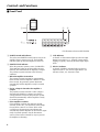
■ Front Panel
1 POWER switch and indicator
This is the main POWER switch. Press to turn on the
amplifier. Press it again to turn off. The POWER
indicator lights up when the amplifier it turned on.
2 PROTECTION indicator
When the protection system is active, the PROTEC-
TION indicator lights up and the speakers are auto-
matically disconnected from the amplifier’s outputs.
The protection system activates in the following
situations:
• When the amplifier is turned on
The protection system activates for approximately
three seconds when the amplifier is turned on. After
three seconds, the protection system deactivates
automatically and the amplifier is ready for normal
operation.
• If a DC voltage is detected at the amplifier’s
outputs
The protection system activates if a DC voltage is
detected at the amplifier’s outputs. Once the DC
voltage problem is corrected, the protection system
deactivates automatically and the amplifier is ready
for normal operation.
• If the amplifier overheats
If the amplifier overheats, the protection system
activates. In this case, you should turn off the ampli-
fier and allow it time to cool down. When it has
cooled down, the protection system deactivates
automatically and the amplifier can be turned on again
ready for normal operation. See the Precautions
section of this Owner’s Manual for ways to prevent
the amplifier overheating.
3 CLIP indicator
A channel’s CLIP indicator lights up when its output
distortion exceeds 1% (i.e., clipping). Output signal
clipping is typically caused by excessive input signal
levels.
4 SIGNAL indicator
A channel’s SIGNAL indicator lights up when its
output exceeds 2 V rms, which is equivalent to 1/2
watt into 8 ohms, or 1 watt into 4 ohms.
1
2
3
4
* The illustration shows model XM6150.

5
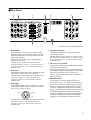
■ Rear Panel
1 HPF switches
These switches are used to turn on and off the HPF
(High Pass Filter) for each channel. When set to ON,
frequencies below 80 Hz are filtered using a 12 dB/
octave high pass filter.
Turn this switch ON if 70V-line, high-impedance
speakers are connected.
In Bridge mode, only the HPF switch of the first
channel in the pair is active, i.e., channel A of pair A–
B, channel C of pair C–D, and channel E of pair E–F
(XM6150 only).
2 Attenuators
These detented controls are used to attenuate the input
signal from –∞ dB to 0 dB for each channel.
In Bridge mode, only the attenuator of the first channel
in the pair is active, i.e., channel A of pair A–B,
channel C of pair C–D, and channel E of pair E–F
(XM6150 only).
3 XLR inputs
These balanced XLR-3-31 type connectors are used to
connect input signals. They are wired pin 1–ground,
pin 2–hot (+), and pin 3–cold (–).
1
2
3
Cold
GroundHot
In Bridge mode, only the XLR input of the first channel
in the pair is active, i.e., channel A of pair A–B,
channel C of pair C–D, and channel E of pair E–F
(XM6150 only).
80
13
4
8
7
52
6
4 Euroblock connectors
These balanced Euroblock connectors are used to
connect input signals.
In Bridge mode, only the Euroblock connector of the
first channel in the pair is active, i.e., channel A of pair
A–B, channel C of pair C–D, and channel E of pair E–
F (XM6150 only).
5 CH A TO ALL CH switch
This switch is used to feed the input signal connected
to channel A to all channels.
When set to EACH CH, the input signal connected to
each channel is amplified and output by each channel
respectively. When set to CH A TO ALL CH,
however, the input signal connected to channel A is
fed to all channels.
6 BRIDGE switches
These switches are used to bridge the following
channel pairs: A–B, C–D, and E–F (XM6150 only).
When set to OFF, the two channels operate indepen-
dently. For example, the signal connected to input
channel A is amplified and output by the channel A
outputs, while the signal connected to input channel B
is amplified and output by the channel B outputs.
When set to BRIDGE, the signal connected to input
channel A is amplified and output by the bridged
outputs A–B, and channel B’s inputs are not used.
* The illustration shows model XM6150.

6
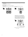
7 GND terminals
This is the grounding screw terminal. If hum or noise occurs, ground (earth) the unit via this jack, or try connecting it
to the chassis of the mixer or preamp, etc.
8 Speaker outputs
These 5-way binding posts are used to connector speakers.
The following illustrations show how speakers should be connected for normal and Bridge mode operation.
Normal mode Bridge mode
Speaker
min. 8Ω
+
–
Speaker
min. 4Ω
Speaker
min. 4Ω
+
–
+
–
In Bridge mode, you can connect multiple high-
impedance speakers (that are compatible with 70V
line output) in parallel. The number of speakers you
can connect is determined by the rated input of each
speaker. For each channel, you can connect speakers
as long as the speakers’ total rated input does not
exceed 150W (for XM6150) or 350W (for XM4220).
Total rated input 150W or less (XM6150)
350W or less (XM4220)
+
–
+
–
+
–
Note: Be sure to use speakers that support the 70V
line-out voltage.

7
Connection
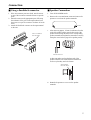
■ Using a Euroblock connector
1. If the wire insertion ports are closed, turn the screws
on top of the connector counterclockwise to open the
ports.
2. Insert the wires into the appropriate ports, following
the indication of the pole on the input terminal, turn
the screws on top of the connector clockwise to fix the
wires.
3. Attach the Euroblock connector to the input terminal
on the unit.
■ Speaker Connection
1. Turn off the POWER switch.
2. Remove the cover attachment screws and remove the
protective cover from the speaker terminals.
Screw
3. After removing approx. 15 mm of insulation from the
ends of the speaker cables, pass the bare ends of the
speaker wires through the holes in the corresponding
speaker terminals and tighten the terminals to securely
clamp the wires. Refer to page 6 for speaker porality.
15mm*
* Shown actual size.
At this time make sure that the bare ends of the
speaker cables do not extend from the terminals in
such a way that they touch the chassis.
Wire should not
touch the chassis.
4. Reattach the protective cover over the speaker
terminals.
+
–
G
Use a screwdriver
to fix the wires.

8
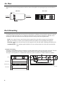
Air Flow
This unit uses a forced cooling system in which air comes in through the front opening and goes out the sides and
rear.
4-6.5 x 11
88
463
480
Unit : mm
248
4-C15
4-ø4.5
76.2
71.5±0.1
71.5±0.1
78
78
Fan kit
Ventilation panel
XM6150/4220
XM6150/4220
Rack Mounting
If multiple high-power amp units are mounted in a rack with poor ventilation, the heat from the amps will cause the
interior of the amp to become very hot, causing the performance of the amps to be impaired. In particular, when
mounting in a rack whose back can not be left open, mount according to the following instructions.
Rack: Leave a gap of 10 cm or more between the rear panel of the rack and the rear panel of the amplifier.
Fan: Use a fan with 1.5 m
3
/min or more maximum wind and 5 mmH
2
O or more maximum static pressure.
Mounting: Install the fan kit on the top slot or the top panel of the rack and install a blanking panel between two
amps.
Ventilation panel:. The ventilation panel should be a 1U size, and more than 35% of the entire area should be
open.
Example of mounting
The figure on the left below shows an example of a fan kit (panels and two fans) on the top slot of the rack. The fans
are Minebia 3115PS-12T-B30 (with 0.9 m
3
/min maximum wind and 5 mmH
2
O maximum static pressure).
The figure on the right below is a dimensional diagram of a panel on which two 3115PS-12T-B30 are installed.
80
Side View Rear View
Air intake Air exhaust
Air exhaust
Front

9
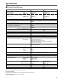
Specifications
■ General Specifications
XM6150 XM4220
Power Output Level (Rated Power) 8Ω 100 W x 6 140 W x 4
20 Hz~20 kHz 4Ω 120 W x 6 180 W x 4
THD+N= 0.2% 8Ω/BRIDGE 240 W x 3 360 W x 2
1 kHz 8Ω 120 W x 6 170 W x 4
THD+N= 0.2% 4Ω 150 W x 6 220 W x 4
8Ω/BRIDGE 300 W x 3 440 W x 2
70.7V/BRIDGE 150 W x 3 350 W x 2
Power Bandwidth Half Power 10 Hz~40 kHz (THD+N= 1%)
Total Harmonic Distortion (THD + N)
20 Hz~20 kHz, Half Power
≤0.2%
Frequency Response 8Ω, Po= 1 W 0 dB, 0.5 dB, –1 dB 20 Hz~50 kHz
Intermodulation distortion (IMD)
60 Hz:7 kHz, 4:1, Half Power
≤0.2%
Channel Separation Half Power, RL= 8Ω, 1 kHz
≥60 dB
Vol. max., input 600Ω shunt
Residual Noise Vol. max. 12.7 kHz LPF ≤ –68 dB ≤–66.5 dB
SN Ratio 12.7 kHz LPF 100 dB
Damping Factor 8Ω, 1f= 1 kHz ≥100
Sensitivity (Vol. max.) Rated Power into 8Ω 0 dB
Voltage Gain (Vol. max.) 32.1 dB 33.6 dB
Input Impedance 30 kΩ/Balanced, 15 kΩ/Unbalanced
Controls Front Panel POWER switch (ON/OFF)
Rear Panel Volume (31 position) /ch
BRIDGE switch (ON/OFF) /2ch
HPFswitch (ON/OFF) /ch
fc=80 Hz, –12 dB/oct.
CH A TO ALL CH switch
Connectors Input XLR-3-31 type/ch
Euroblock connector
Output 5-way binding posts
Indicators POWER Green
PROTECTION Red
CLIP Red
SIGNAL Green
Protection Circuits POWER switch ON muting, DC detection,
Temp. detection (heatsink temp ≥ 85°C)
PC limiter RL ≤ 2 Ω
Fan Speed Low/~50°C, Variable, High/70°C~
Power Requirements US & Canada 120 V, 60 Hz
Europe 230 V, 50 Hz
Other 240 V, 50 Hz
Power Consumption Idling 45 W 45 W
1/8 output power, 4Ω 400 W/550 VA 400 W/500 VA
Maximum output, 4Ω 1800 W 1800 W
Dimensions (W x H x D) 480 x 132 x 319 mm
Weight 18 kg 18 kg
Accesaries Euroblock connector x 6 Euroblock connector x 4
0 dB=0.775 Vrms, Half Power=1/2 Power Output Level (Rated Power)
Specifications subject to change without notice.
For European Model
Purchaser/User information specified in EN55103-1 and EN55103-2.
Inrush Current: 56A
Conformed Enviroment: E1, E2, E3 and E4.

10
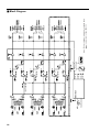
■ Block Diagram
Note: The block diagram indicated in the dotted frame
( ) applies only to model XM6150

11
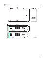
■ Dimensions
Unit: mm
D: 319
W: 480
H: 132

12
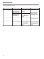
Troubleshooting
The following table lists the main causes of abnormal operation and the corrective measures required as well as the
protective circuit operation in each case.
Protection CircuitRemedyPossible CauseIndicator
CLIP indicator lights up
PROTECTION indicator
lights up
There is a short at the
amplifier’s speaker
outputs, the speaker’s
inputs, or in the wiring.
The impedance of the
connected speaker
is too low.
The heat sink temperature
has exceeded 90°C.
A DC voltage of ±2 V
or greater was detected
in the amplifier’s output
circuit.
Locate and remove
the short.
Check the ventilation
around the amplifier
and improve the airflow
if necessary.
Consult your dealer
or a Yamaha service
center.
The PC limiter circuit
activates to protect
the power transistors.
The thermal protection
circuit activates to
protect the power
transistors.
The output relay activates
to protect the speaker
system.
Use a speaker with a
minimum impedance
of 4Ω (8Ω in Bridge
mode).

YAMAHA CORPORATION
V455890 R0 1 AP 16 Pro Audio Division, #18/3
P.O. Box 3, Hamamatsu, 430-8651, Japan
NP Printed in Taiwan
-
 1
1
-
 2
2
-
 3
3
-
 4
4
-
 5
5
-
 6
6
-
 7
7
-
 8
8
-
 9
9
-
 10
10
-
 11
11
-
 12
12
-
 13
13


Yamaha XM4220 Manual de utilizare
- Categorie
- Amplificatoare audio
- Tip
- Manual de utilizare
- Acest manual este potrivit și pentru
în alte limbi
- Türkçe: Yamaha XM4220 Kullanım kılavuzu
- français: Yamaha XM4220 Manuel utilisateur
- čeština: Yamaha XM4220 Uživatelský manuál
- русский: Yamaha XM4220 Руководство пользователя
- English: Yamaha XM4220 User manual
- polski: Yamaha XM4220 Instrukcja obsługi
- Deutsch: Yamaha XM4220 Benutzerhandbuch
- 日本語: Yamaha XM4220 ユーザーマニュアル
- italiano: Yamaha XM4220 Manuale utente
- español: Yamaha XM4220 Manual de usuario
- svenska: Yamaha XM4220 Användarmanual
- dansk: Yamaha XM4220 Brugermanual
- português: Yamaha XM4220 Manual do usuário
- Nederlands: Yamaha XM4220 Handleiding
Lucrări înrudite
-
Yamaha XM4180 Manualul proprietarului
-
-
-
-
-
-
-
-
-
Yamaha MA2030 Manualul proprietarului