Yamaha DSP-AZ2 Manualul proprietarului
- Categorie
- Receptor
- Tip
- Manualul proprietarului

OWNER’S MANUAL
MODE D’EMPLOI
BEDIENUNGSANLEITUNG
BRUKSANVISNING
MANUALE DI ISTRUZIONI
MANUAL DE INSTRUCCIONES
GEBRUIKSAANWIJZING
DSP-AZ2
GB
AV Amplifier
Amplificateur Audio-Video
YAMAHA ELECTRONICS CORPORATION, USA 6660 ORANGETHORPE AVE., BUENA PARK, CALIF. 90620, U.S.A.
YAMAHA CANADA MUSIC LTD. 135 MILNER AVE., SCARBOROUGH, ONTARIO M1S 3R1, CANADA
YAMAHA ELECTRONIK EUROPA G.m.b.H. SIEMENSSTR. 22-34, 25462 RELLINGEN BEI HAMBURG, F.R. OF GERMANY
YAMAHA ELECTRONIQUE FRANCE S.A. RUE AMBROISE CROIZAT BP70 CROISSY-BEAUBOURG 77312 MARNE-LA-VALLEE CEDEX02, FRANCE
YAMAHA ELECTRONICS (UK) LTD. YAMAHA HOUSE, 200 RICKMANSWORTH ROAD WATFORD, HERTS WD1 7JS, ENGLAND
YAMAHA SCANDINAVIA A.B. J A WETTERGRENS GATA 1, BOX 30053, 400 43 VÄSTRA FRÖLUNDA, SWEDEN
YAMAHA MUSIC AUSTRALIA PTY, LTD. 17-33 MARKET ST., SOUTH MELBOURNE, 3205 VIC., AUSTRALIA
Printed in Malaysia
V977840
DSP-AZ2
0100DSPAZ2(GB)-cv1/4 02.8.22, 1:26 PM1

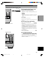
1 To assure the finest performance, please read this manual
carefully. Keep it in a safe place for future reference.
2 Install this sound system in a well ventilated, cool, dry, clean
place — away from direct sunlight, heat sources, vibration,
dust, moisture, and/or cold. Allow ventilation space of at
least 30 cm on the top, 20 cm on the left and right, and
20 cm on the back of this unit.
3 Locate this unit away from other electrical appliances,
motors, or transformers to avoid humming sounds.
4 Do not expose this unit to sudden temperature changes from
cold to hot, and do not locate this unit in a environment with
high humidity (i.e. a room with a humidifier) to prevent
condensation inside this unit, which may cause an electrical
shock, fire, damage to this unit, and/or personal injury.
5 Avoid installing this unit where foreign object may fall onto
this unit and/or this unit may be exposed to liquid dripping
or splashing. On the top of this unit, do not place:
– Other components, as they may cause damage and/or
discoloration on the surface of this unit.
– Burning objects (i.e. candles), as they may cause fire,
damage to this unit, and/or personal injury.
– Containers with liquid in them, as they may fall and liquid
may cause electrical shock to the user and/or damage to
this unit.
6 Do not cover this unit with a newspaper, tablecloth, curtain,
etc. in order not to obstruct heat radiation. If the temperature
inside this unit rises, it may cause fire, damage to this unit,
and/or personal injury.
7 Do not plug in this unit to a wall outlet until all connections
are complete.
8 Do not operate this unit upside-down. It may overheat,
possibly causing damage.
9 Do not use force on switches, knobs and/or cords.
10 When disconnecting the power cord from the wall outlet,
grasp the plug; do not pull the cord.
11 Do not clean this unit with chemical solvents; this might
damage the finish. Use a clean, dry cloth.
12 Only voltage specified on this unit must be used. Using this
unit with a higher voltage than specified is dangerous and
may cause fire, damage to this unit, and/or personal injury.
YAMAHA will not be held responsible for any damage
resulting from use of this unit with a voltage other than
specified.
13 To prevent damage by lightning, disconnect the power cord
from the wall outlet during an electrical storm.
14 Do not attempt to modify or fix this unit. Contact qualified
YAMAHA service personnel when any service is needed.
The cabinet should never be opened for any reasons.
15 When not planning to use this unit for long periods of time
(i.e. vacation), disconnect the AC power plug from the wall
outlet.
16 Be sure to read the “TROUBLESHOOTING” section on
common operating errors before concluding that this unit is
faulty.
17 Before moving this unit, press STANDBY/ON to set this
unit in the standby mode, and disconnect the AC power plug
from the wall outlet.
18 VOLTAGE SELECTOR (For China and General models
only)
The VOLTAGE SELECTOR on the rear panel of this unit
must be set for your local main voltage BEFORE plugging
into the AC main supply.
Voltages are 110/120/220/240 V AC, 50/60 Hz.
CAUTION: READ THIS BEFORE OPERATING YOUR UNIT.
WARNING
TO REDUCE THE RISK OF FIRE OR ELECTRIC SHOCK,
DO NOT EXPOSE THIS UNIT TO RAIN OR MOISTURE.
This unit is not disconnected from the AC power source as
long as it is connected to the wall outlet, even if this unit
itself is turned off. This state is called the standby mode. In
this state, this unit is designed to consume a very small
quantity of power.
■ For U.K. customers
If the socket outlets in the home are not suitable for the
plug supplied with this appliance, it should be cut off and
an appropriate 3 pin plug fitted. For details, refer to the
instructions described below.
Note
• The plug severed from the mains lead must be destroyed, as a
plug with bared flexible cord is hazardous if engaged in a live
socket outlet.
■ Special Instructions for U.K.
Model
IMPORTANT
THE WIRES IN MAINS LEAD ARE COLOURED
IN ACCORDANCE WITH THE FOLLOWING
CODE:
Blue: NEUTRAL
Brown: LIVE
As the colours of the wires in the mains lead of this
apparatus may not correspond with the coloured
markings identifying the terminals in your plug,
proceed as follows:
The wire which is coloured BLUE must be connected
to the terminal which is marked with the letter N or
coloured BLACK. The wire which is coloured
BROWN must be connected to the terminal which is
marked with the letter L or coloured RED.
Making sure that neither core is connected to the earth
terminal of the three pin plug.
CAUTION
0101DSPAZ2_Cau_EN(GB) 02.8.22, 0:15 PM2

English
INTRODUCTION
PREPARATION
BASIC
OPERATION
ADDITIONAL
INFORMATION
ADVANCED
OPERATION
1
CONTENTS
ADVANCED OPERATION
REMOTE CONTROL FEATURES ................... 41
Control Area ............................................................ 41
Setting the Manufacturer Code ............................... 42
Learn Feature .......................................................... 43
Changing the Source Name in the Display
Window ............................................................... 44
Using the Macro Feature ......................................... 45
Clearing Learned Functions, Macros, Renamed
Source Names, and Setup Manufacturer
Codes ................................................................... 47
Clearing a Learned Function ................................... 48
Clearing a Macro Function ...................................... 48
Each Component Control Area ............................... 50
SET MENU ........................................................... 55
Adjusting the Items on the SET MENU ................. 55
1 SPEAKER SET (speaker mode settings) ............ 56
2 LOW FRQ TEST ................................................ 60
3 L/R BALANCE (balance of the left and right
main speakers)..................................................... 60
4 HP TONE CTRL (headphone tone control) ........ 61
5 CENTER GEQ (center graphic equalizer) .......... 61
6 INPUT RENAME ............................................... 61
7 I/O ASSIGNMENT ............................................. 62
8 INPUT MODE (initial input mode) .................... 63
9 PARAM. INI (parameter initialization) .............. 63
10LFE LEVEL ........................................................ 63
11D-RANGE (dynamic range) ............................... 64
12SP DELAY .......................................................... 64
13DISPLAY SET .................................................... 65
14MEMORY GUARD ............................................ 66
156CH INPUT SET ................................................ 66
ADJUSTING THE LEVEL OF THE EFFECT
SPEAKERS ....................................................... 67
SLEEP TIMER ..................................................... 68
Setting the Sleep Timer ........................................... 68
Canceling the Sleep Timer ...................................... 68
ADDITIONAL INFORMATION
SOUND FIELD PROGRAM PARAMETER
EDITING .......................................................... 69
What Is a Sound Field? ........................................... 69
Sound Field Program Parameters ............................ 69
Changing Parameter Settings .................................. 70
Resetting a Parameter to the Factory-set Value ....... 70
DIGITAL SOUND FIELD PARAMETER
DESCRIPTIONS .............................................. 71
TROUBLESHOOTING ....................................... 75
GLOSSARY .......................................................... 79
SPECIFICATIONS .............................................. 81
INTRODUCTION
CONTENTS ............................................................ 1
FEATURES ............................................................. 2
GETTING STARTED ............................................ 3
Checking the Package Contents ................................ 3
Installing Batteries in the Remote Control ................ 3
CONTROLS AND FUNCTIONS ......................... 4
Front Panel ................................................................ 4
Remote Control ......................................................... 6
Using the Remote Control ......................................... 7
Front Panel Display ................................................... 8
Rear Panel ................................................................. 9
PREPARATION
SPEAKER SETUP ............................................... 10
Speakers to Be Used ................................................ 10
Speaker Placement .................................................. 11
Connecting the Speakers ......................................... 12
CONNECTIONS .................................................. 15
Before Connecting Components ............................. 15
Connecting Video Components ............................... 15
Connecting Audio Components .............................. 18
Connecting to an External Amplifier ...................... 20
Connecting to the 6CH INPUT Jacks ..................... 20
Connecting the Power Supply Cords ...................... 21
Turning on the Power .............................................. 22
ON-SCREEN DISPLAY (OSD) .......................... 23
OSD Modes ............................................................. 23
Selecting the OSD Mode ......................................... 23
SPEAKER MODE SETTINGS .......................... 24
Summary of SPEAKER SET Items 1A
through 1H .......................................................... 24
ADJUSTING THE SPEAKER OUTPUT
LEVELS ............................................................ 25
Before You Begin .................................................... 25
TEST DOLBY SUR. ............................................... 25
TEST DSP ............................................................... 27
BASIC OPERATION
BASIC PLAYBACK ............................................. 28
Input Modes and Indications ................................... 30
Selecting a Sound Field Program ............................ 31
Selecting PRO LOGIC, PRO LOGIC
or Neo: 6 ............................................................. 32
DIGITAL SOUND FIELD PROCESSING
(DSP) ................................................................. 34
Understanding Sound Fields ................................... 34
Hi-Fi DSP Programs ............................................... 34
CINEMA-DSP ........................................................ 34
Straight Decode ....................................................... 35
Sound Field Effect ................................................... 35
Features of DSP Programs ...................................... 36
Table of Program Names for Each Input Format .... 39
BASIC RECORDING .......................................... 40
0102DSPAZ2_1-9_EN(GB) 02.8.22, 0:15 PM1

2
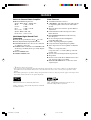
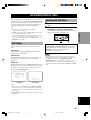
Manufactured under license from Dolby Laboratories.
“Dolby”, “Pro Logic”, and the double-D symbol are trademarks
of Dolby Laboratories.
“DTS”, “DTS-ES Extended Surround” and “Neo: 6” are
trademarks of Digital Theater System, Inc.
FEATURES
Built-in 8-Channel Power Amplifier
◆ Minimum RMS Output Power
(0.02% THD, 20 Hz – 20 kHz, 8Ω)
Main: 130 W + 130 W
Center: 130 W
Rear: 130 W + 130 W
Rear center: 130 W
(0.05% THD, 1 kHz, 8Ω)
Front effect: 25 W + 25 W
Multi-Mode Digital Sound Field
Processing
◆ Dolby Pro Logic/Dolby Pro Logic Decoder
◆ Dolby Digital/Dolby Digital EX Decoder
◆ DTS/DTS ES Matrix 6.1, Discrete 6.1, DTS 96/
24, DTS Neo: 6 Decoder
◆ CINEMA DSP: Combination of YAMAHA DSP
Technology and Dolby Pro Logic, Dolby Digital
or DTS
◆ Virtual CINEMA DSP
◆ SILENT CINEMA DSP
Other Features
◆ 192-kHz/24-bit D/A Converter
◆ “SET MENU” which Provides You with 15 Items
for Optimizing This Unit for Your Audio/Video
System
◆ Test Tone Generator for Easier Speaker Balance
Adjustment
◆ 6-Channel External Decoder Input for Other
Future Formats
◆ BASS EXTENSION Button for Reinforcing
Bass Response
◆ On Screen Display Function Helpful in
Controlling This Unit
◆ S Video Signal Input/Output Capability
◆ Component Video Input/Output Capability
◆ Video Signal Conversion Capability for Monitor
Out:
S Video → Composite Video
Composite Video → S Video (Europe and U.K.
models only)
◆ Optical and Coaxial Digital Audio Signal Jacks
◆ Sleep Timer
◆ Remote Control with Preset Manufacturer Codes
and “Learning” Macro Capability
◆ PROCESSOR DIRECT for no alteration of the
original signal
• y indicates a tip for your operation.
• Some operations can be performed by using either the buttons on the main unit or on the remote control. In cases when the button
names differ between the main unit and the remote control, the button name on the remote control is given in parentheses in this
manual.
• This manual is printed prior to production. Design and specifications are subject to change in part for the purpose of the improvement
in operativity and others. In this case the product has priority.
0102DSPAZ2_1-9_EN(GB) 02.10.1, 1:03 PM2

English
INTRODUCTION PREPARATION
BASIC
OPERAIONT
ADVANCED
OPERATION
ADDITIONAL
INFORMATION
APPENDIX
3
TRANSMIT
RE-NAME
STANDBY
6CH INPUT
SOUND
SYSTEM
CLEAR LEARN MACRO
OFF ON
MACRO
PHONO
A
B
CD
DVD
VCR2/DVR
VCR 1
TITLE
MENU
CHAPTER
PAUSESTOPPOWER
REC
HALL 1
EX/ES
DSP
10KEY
ROCK
CONCERT
MOVIE
THEATER 1
MOVIE
THEATER 2
MUTE
VOLUME
STEREO
TV INPUT
TV VOL
CH
PRESET
DISC
PARAMETER
SET MENU
EFFECT
LEVEL
ON SCREEN
TESTSLEEP
TV MUTE
MUSIC
VIDEO
TV
THEATER
ENTER-
TAINMENT
HALL 2
CHURCH
JAZZ CLUB
SELECT
/DTS
SUR.
CHP/INDEX
A/B/C/D/E
SELECT
DISPLAY
SEARCH
SOURCE
PLAY
–+
ENTER
D-TV/LD
CBL/SAT
CD-R
MD/TAPE
TUNER
V-AUX
POWER
1
5
9
6
10
0
10
100
11 12
78
234
+
+
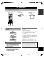
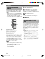
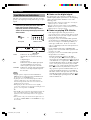
Installing Batteries in the Remote
Control
1 Open the battery compartment cover.
2 Insert three supplied batteries (LR6) in the
correct direction by aligning the + and –
marks on the batteries with the polarity
markings (+ and –) on the inside of the
battery compartment.
3 After new batteries are correctly inserted,
press the RESET button in the battery
compartment using a ball point pen or
similar object. (This does not clear the
contents of the memory.)
4 Replace the cover as pressing until it snaps
into place.
■ Notes on batteries
• Change all of the batteries if you notice the condition
like; the operating range of the remote control
decreases, the indicator does not flash or its light
becomes dim.
• Do not use old batteries together with new ones.
• Do not use different types of batteries (such as alkaline
and manganese batteries) together. Read the packaging
carefully as these different types of batteries may have
the same shape and color.
• If the batteries have leaked, dispose of them
immediately. Avoid touching the leaked material or
letting it come into contact with clothing, etc. Clean
the battery compartment thoroughly before installing
new batteries.
If the remote control is without batteries for more than
3 minutes, or if exhausted batteries remain in the
remote control, the contents of the memory may be
cleared. When the memory is cleared, insert new
batteries, set up the manufacturer code and program
any acquired functions that may have been cleared.
Batteries (LR6) × 3Remote control
GETTING STARTED
Checking the Package Contents
Check your package to make sure it has the following items.
Power Cord
(Europe, General and China
models only)
RESET button
0102DSPAZ2_1-9_EN(GB) 02.8.22, 0:15 PM3

4
BASS
VOLUME
VIDEO AUX
SILENT
PROGRAM
STEREO
REC OUT
SPEAKERS
INPUT
MODE
BASS
EXTENSION
PROCESSOR
DIRECT
SET MENU
PHONES
EFFECT
SOURCE
MD/TAPE
CD–R
TUNER
CD
PHONO
DVD
D–TV/LD
CBL/SAT
VCR 1
V–AUX
VCR2
/DVR
NEXT
+–
S VIDEO VIDEO AUDIO OPTICALLR
STANDBY
/
ON
NATURAL SOUND AV AMPLIFIER DSP-AZ2
TREBLE
–
+
–
+
6CH
INPUT
AB
DIGITAL
1 2 34 5 6
7q
w
e
r t y u8 9 0
io
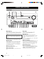
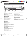
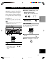
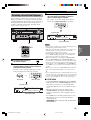
CONTROLS AND FUNCTIONS
Front Panel
1 STANDBY/ON
Turns on and sets this unit in the standby mode. When
you turn on this unit, you will hear a click and there will
be a 4 to 5-second delay before this unit can reproduce
sound.
Standby mode
In this mode, this unit consumes a small amount of
power to receive infrared-signals from the remote
control.
2 INPUT selector
Selects the input source you want to listen to or watch.
3 (INPUT) MODE
Sets the priority for the types of input signals (AUTO,
DTS, ANALOG) to receive when one component is
connected to two or more input jacks of this unit (see
page 30). Priority cannot be set when 6CH INPUT is
selected as the input source.
4 Remote control sensor
Receives signals from the remote control.
5 Front panel display
Shows information about the operational status of this
unit.
6 VOLUME
Controls the output level of all audio channels.
This does not affect the REC OUT level.
7 PHONES jack
Outputs audio signals for private listening with
headphones. When you connect headphones, no signals
are output to the PRE OUT/MAIN IN jacks or to the
speakers.
(There is an exception depending on the “1H SP B SET”
setting on the SET MENU.)
8 BASS EXTENSION
Turns on or off the BASS EXTENSION function at each
time the button is pressed, this feature boosts the bass
frequency of the left and right main channels by +6 dB
(60 Hz) while maintaining overall tonal balance. This
boost is useful if you do not use a subwoofer.
9 PROCESSOR DIRECT
Turns on or off the PROCESSOR DIRECT function at
each time the button is pressed. When this is on, BASS,
TREBLE, and BASS EXTENSION are bypassed,
eliminating any alteration of the original signal.
0102DSPAZ2_1-9_EN(GB) 02.8.22, 0:15 PM4

5
English
INTRODUCTION PREPARATION
BASIC
OPERAIONT
ADVANCED
OPERATION
ADDITIONAL
INFORMATION
APPENDIX
CONTROLS AND FUNCTIONS
D
I
G
I
T
A
L
N
ATU
RA
L S
O
UN
D AV A
M
PLIFIER
DS
P
-A
Z2
To open, press gently on the lower part of the panel.
0 SPEAKERS A/B
Turn on or off the set of main speakers connected to the A
and/or B terminals on the rear panel at each time its
corresponding button is pressed.
(Depending on the “1H SP B SET” setting on the SET
MENU, the output from each speaker varies when
SPEAKER B is set to on.)
q BASS
Adjusts the low-frequency response for the left and right
main channels.
Turn the control to the right to increase or to the left to
decrease the low-frequency response.
w TREBLE
Adjusts the high-frequency response for the left and right
main channels.
Turn the control to the right to increase or to the left to
decrease the high-frequency response.
Note
• If you increase or decrease the high-frequency or the low-
frequency sound to an extreme level, the tonal quality from the
center and rear speakers may not match that of the left and
right main speakers.
e REC OUT
Selects the source you want to direct to the audio/video
recorder independent of the source you are listening to or
watching in the main room. When set to the SOURCE
position, the input source is directed to all outputs.
r STEREO/EFFECT
Switches the normal stereo or DSP effect reproduction.
When STEREO is selected, 2-channel input signals are
directed to the main left and right speakers without effect
sounds. All Dolby Digital and DTS audio signals except
for the LFE channel are mixed down to the main left and
right speakers.
t NEXT
Displays SET MENU items. This button works like n on
the remote control when using the SET MENU.
y PROGRAM l / h
Selects the DSP program.
u 6CH INPUT
Selects the source connected to the 6CH INPUT jacks.
The source selected by pressing 6CH INPUT takes
priority over the source selected with INPUT (or the input
selector buttons on the remote control).
i SET MENU +/–
Adjusts the settings and parameter values of SET MENU
items.
o VIDEO AUX jacks
Inputs audio and video signals from a portable external
source such as a game console. To reproduce source
signals from these jacks, select V-AUX as the input
source.
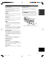
■ Opening and closing the front
panel door
When you want to use the controls behind the front panel
door, open the door gently pressing on the lower part of
the panel. When you are not using them, close the door.
0102DSPAZ2_1-9_EN(GB) 02.8.22, 0:15 PM5

6
CONTROLS AND FUNCTIONS
TRANSMIT
RE-NAME
STANDBY
6CH INPUT
SOUND
SYSTEM
CLEAR LEARN MACRO
OFF ON
MACRO
PHONO
A
B
CD
DVD
VCR2/DVR
VCR 1
TITLE
MENU
CHAPTER
PAUSESTOPPOWER
REC
HALL 1
EX/ES
DSP
10KEY
ROCK
CONCERT
MOVIE
THEATER 1
MOVIE
THEATER 2
MUTE
VOLUME
STEREO
TV INPUT
TV VOL
CH
PRESET
DISC
PARAMETER
SET MENU
EFFECT
LEVEL
ON SCREEN
TESTSLEEP
TV MUTE
MUSIC
VIDEO
TV
THEATER
ENTER-
TAINMENT
HALL 2
CHURCH
JAZZ CLUB
SELECT
/DTS
SUR.
CHP/INDEX
A/B/C/D/E
SELECT
DISPLAY
SEARCH
SOURCE
PLAY
– +
ENTER
D-TV/LD
CBL/SAT
CD-R
MD/TAPE
TUNER
V-AUX
POWER
1
5
9
6
10
0
10
100
11 12
78
234
+
+
1
2
3
4
5
6
7
0
w
e
r
t
9
8
q
y
u
i
o
p
d
g
f
s
j
k
h
a
l
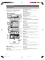
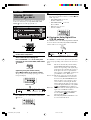
Remote Control
This section describes the controls and their functions of
the remote control. See “REMOTE CONTROL
FEATURES” on pages 41 to 54 for operating other
components with this remote control.
1 Infrared window
Outputs infrared control signals. Aim this window at the
component you want to operate.
2 RE-NAME
Used for changing the input source name in the display
window (see page 44).
3 TRANSMIT indicator
Flashes while the remote control is sending signals.
4 STANDBY
Sets this unit in the standby mode.
5 SYSTEM POWER
Turns on the power of this unit.
6 Display window
Shows the selected source component that you are
controlling.
7 SOURCE SELECT k/n
Selects the another component to control independently
from the input that has been selected by pressing an input
selector button.
8 LIGHT
Turn the light on or off. When you press this button once,
the light turns on for about ten seconds. Press again to
turn off the light.
9 10KEY/DSP
Selects the numeric button (10KEY) mode or DSP mode.
0 Operation buttons
Provides functions such as play, stop, skip, etc. for
operating your other components selected by the input
selector buttons.
q EX/ES
Turns on or off the Dolby Digital EX or DTS ES decoder
with 10 KEY/DSP set to the DSP position.
w LEVEL
Selects the effect speaker channel to be adjusted and sets
the level.
e ON SCREEN
Selects the on-screen display (OSD) mode for your video
monitor.
r SLEEP
Sets the sleep timer.
t TEST
Outputs the test tone to adjust the speaker levels.
y CLEAR
Used for clearing functions acquired when using the learn
and rename features, and set manufacturer codes (see
pages 47 and 48).
u LEARN
Used for setting up the manufacturer code or for
programming the functions of other remote controls (see
pages 42 to 44).
0102DSPAZ2_1-9_EN(GB) 02.8.22, 0:15 PM6

7
English
INTRODUCTION PREPARATION
BASIC
OPERAIONT
ADVANCED
OPERATION
ADDITIONAL
INFORMATION
APPENDIX
CONTROLS AND FUNCTIONS
BASS
VOLUME
VIDEO AUX
SILENT
PROGRAM
STEREO
REC OUT
SPEAKERS
INPUT
MODE
BASS
EXTENSION
PROCESSOR
DIRECT
SET MENU
PHONES
EFFECT
SOURCE
MD/TAPE
CD–R
TUNER
CD
PHONO
DVD
D–TV/LD
CBL/SAT
VCR 1
V–AUX
VCR2
/DVR
NEXT
+–
S VIDEO VIDEO AUDIO OPTICALLR
STANDBY
/
ON
NATURAL SOUND AV AMPLIFIER DSP-AZ2
TREBLE
–
+
–
+
6CH
INPUT
AB
DIGITAL
30°30°
Approximately 6 m (20 feet)
i MACRO
Used to program a series of operations for control by a
single button (see pages 46 and 47).
o MACRO ON/OFF
Turns the macro function on and off.
p Å and ı
Switch the control area for the extra components that are
not connected to this unit without changing the input.
a Input selector buttons
Select the input source and change the control area.
s 6CH INPUT
Selects the source connected to the 6CH INPUT jacks.
d DSP program/Numeric buttons
Select DSP programs or numbers according to the
position of 10KEY/DSP.
f MUTE
Mutes the sound. The MUTE indicator turns on when the
MUTE function is on. Press again to restore the audio
output to the previous volume level.
g VOLUME +/–
Increases or decreases the volume level.
h STEREO/EFFECT
Switches the normal stereo or DSP effect reproduction.
When STEREO is selected, 2-channel input signals are
directed to the main left and right speakers without effect
sounds. All Dolby Digital and DTS audio signals except
for the LFE channel are also directed to the main left and
right speakers.
j PARAMETER/SET MENU
Selects the PARAMETER mode or SET MENU mode.
k Cursor buttons k/n/–/+
Select and adjust DSP program parameters and SET
MENU items according to the position of PARAMETER/
SET MENU.
l Cover
Slides down to use the various setup buttons. Slides up
when these buttons are not being used.
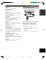
Using the Remote Control
The remote control transmits a directional infrared beam.
Be sure to aim the remote control directly at the remote
control sensor on the main unit during operation.
■ Handling the remote control
• Do not spill water or other liquids on the remote
control.
• Do not drop the remote control.
• Do not leave or store the remote control in the
following types of conditions:
– high humidity or temperature such as near a heater,
stove or bath;
– dusty places; or
– in places subject to extremely low temperatures.
0102DSPAZ2_1-9_EN(GB) 02.8.22, 0:15 PM7

8
CONTROLS AND FUNCTIONS
RL
LCR
RC RR
LFE
VIRTUAL
DTS
Neo
MOVIE TV THEATER
ENTERTAINMENT12
:6
DOLBY DIGITAL
PRO
LOGIC
VCR DVD TUNER CD
PHONO
CD RV AUX
DSP
EX
MATRIXDISCRETE
ES
PCM
1
SILENT
96/24
SP
DIGITAL
VCR2/DVR
CBL
/
SAT
MD
/
TAPE
TV
/
LD
P. DIRECT
BASS
MUTE VOLUME
SLEEP
D
96
K
Hz
/
24bit
PRO LOGIC
/
AB
dB
ft
m
S
0q r t y iu
2
14576 89
w e
3
1
DSP
indicator
Lights up when you select a digital sound field program.
2 Decoder indicators
When any of the decoders equipped on this unit
functions, the indicator lights up.
3 VIRTUAL indicator
Lights up when using Virtual CINEMA DSP (see page
33).
4 Input source indicator
Shows the current input source with a cursor.
5 BASS indicator
Lights up while BASS EXTENSION is on.
6 SLEEP indicator
Lights up while the sleep timer is on.
7 MUTE indicator
Lights up while the MUTE function is on.
8 96/24 indicator
Lights up when the DTS 96/24 signal is input to this unit.
9 VOLUME level indicator
Indicates the volume level.
0
PCM
indicator
Lights up when this unit is reproducing PCM (pulse code
modulation) digital audio signals.
q SILENT indicator
Lights up when headphones are connected with the sound
effect (see “SILENT CINEMA DSP” on page 33).
w SP A B indicator
Lights up according to which set of main speakers is
selected. Both indicators light up when both sets of
speakers are selected.
e Headphones indicator
Lights up when headphones are connected.
Front Panel Display
r DSP program indicators
The name of the selected DSP program lights up when
the ENTERTAINMENT, MOVIE THEATER 1, MOVIE
THEATER 2, TV THEATER or V/DTS SURROUND
DSP program is selected.
t Multi-information display
Shows the current DSP program name and other
information when adjusting or changing settings.
y P. DIRECT
Lights up while PROCESSOR DIRECT is on.
u Input channel indicator
Indicates the channel components of input signals being
received.
i
LFE
indicator
Lights up when the input signal contains the LFE signal.
0102DSPAZ2_1-9_EN(GB) 02.8.22, 0:15 PM8

9
English
INTRODUCTION PREPARATION
BASIC
OPERAIONT
ADVANCED
OPERATION
ADDITIONAL
INFORMATION
APPENDIX
CONTROLS AND FUNCTIONS
AC OUTLETS
SWITCHED
50W MAX. TOTAL
AC IN
CENTER
SUB
WOOFER
S VIDEO
MONITOR OUT
VIDEO
DIGITAL OUTPUT
DIGITAL
INPUT
6CH INPUT
GND
AUDIO AUDIO VIDEO
CONTROL
OUT
SPEAKERS
REMOTE
IN
OUT
1
2
RC-232C
+12V
15mA
MAX.
COMPONENT VIDEO
S VIDEO
DVD
D-TV
/LD
CBL
/SAT
VIDEO
P
R
DVD
MONITOR
OUT
CBL
/SAT
MAIN
IN
OUT
MAIN
REAR CENTER
(SURROUND)
FRONT
EFFECT
REAR
CENTER
REAR
CENTER
PRE OUT/MAIN IN
IMPEDANCE SELECTOR
SET BEFORE POWER ON
SUB
WOOFER
CENTER
REAR
FRONT EFFECT
REAR CENTER
P
B
Y
R
R
L
L
R
L
R
L
R
L
R
L
R
L
R
L
OPTICAL
OPTICAL
MD
/
TAPE
IN
(
PLAY
)
IN
(
PLAY
)
OUT
(
REC
)
OUT
(
REC
)
CD-R
CD-R
MD/TAPE
CD-R
DVD
CBL
/SAT
CD
CD
PHONO
IN
OUT
OUT
TUNER
VCR 2
/DVR
VCR 1
IN
MAIN
SURROUND
CD
D-TV
/LD
(SURROUND)
COAXIAL
+
–
–
+
+
–
–
+
+
–
–
+
+
–
–
+
+
–
–
+
REAR CENTER
A+B
REAR
8ΩMIN./
SPEAKER
8ΩMIN./
SPEAKER
8ΩMIN./
SPEAKER
8ΩMIN./
SPEAKER
8ΩMIN./
SPEAKER
16ΩMIN./
SPEAKER
CENTER
FRONT
MAIN A OR B
:
:
:
:
:
:
MAIN A OR B
FRONT
6ΩMIN./
SPEAKER
4ΩMIN./
SPEAKER
6ΩMIN./
SPEAKER
6ΩMIN./
SPEAKER
4ΩMIN./
SPEAKER
REAR CENTER
CENTER
REAR
:
:
:
:
:
A + B
8ΩMIN./
SPEAKER
:
A
B
VOLTAGE
SELECTOR
1
9
0 2e
2
3
5
8
7
4
6
q w
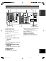
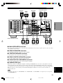
(General and China models)
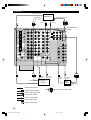
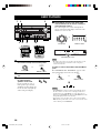
1 DIGITAL OUTPUT jacks
2 Audio component jacks
See pages 18 and 19 for connection information.
3 Video component jacks
See pages 15 to 17 for connection information.
4 RS-232C
These are control expansion terminals for commercial
use. Consult your dealer for details.
5 Speaker terminals
See pages 12 and 13 for connection information.
6 VOLTAGE SELECTOR (General and China
models only)
See page 21.
7 AC OUTLETS
Use these outlets to supply power to your other A/V
components (see page 21).
8 AC INLET (Europe, General and China
models only)
Use this inlet to plug in the supplied power cable (see
page 21).
9 DIGITAL INPUT jacks
0 6CH INPUT jacks
See page 20 for connection information.
q REMOTE IN/OUT jacks / CONTROL OUT jacks
(General and China models only)
These are control expansion jacks for commercial use.
w PRE OUT/MAIN IN jacks
See page 20 for connection information.
e IMPEDANCE SELECTOR switch
Use this switch to match the amplifier output to your
speaker impedance (see page 14). Set this unit in the
standby mode before you change the setting of this
switch.
Rear Panel
0102DSPAZ2_1-9_EN(GB) 02.8.22, 0:15 PM9

10
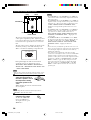
SPEAKER SETUP
This unit has been designed to provide the best sound-
field quality with an 8-speaker system, using left and right
main speakers, left and right rear speakers, left and right
front effect speakers and a center and rear center
speakers. If you use different brands of speakers (with
different tonal qualities) in your system, the tone of a
moving human voice and other types of sound may not
shift smoothly. We recommend that you use speakers
from the same manufacturer or speakers with the same
tonal quality.
The main speakers are used for the main source sound
plus the effect sounds. They will probably be the speakers
from your present stereo system. The rear speakers are
used for the effect and surround sounds, and the center
speaker is for the center sounds (dialog, vocals, etc.). The
front effect speakers are used for the effect sound. If for
some reason it is not practical to use one of speakers (for
example, a center speaker), you can do without it. Best
results, however, are obtained with the full system.
The main speakers should be high-performance models
and have enough power-handling capacity to accept the
maximum output of your audio system. The other
speakers do not have to be equal to the main speakers. For
precise sound localization, however, it is ideal to use the
models of equivalent performance with the main
speakers.
PREPARATION
■ Use of a subwoofer expands your
sound field
It is also possible to further expand your system with the
addition of a subwoofer. The use of a subwoofer is
effective not only for reinforcing bass frequencies from
any or all channels, but also for reproducing the LFE
(low-frequency effect) channel with high fidelity when
the Dolby Digital signal or the DTS signal is played back.
The YAMAHA Active Servo Processing Subwoofer
System is ideal for natural and lively bass reproduction.
CAUTION
Use magnetically shielded speakers. If this type of
speakers still creates the interference with a monitor,
place the speakers away from the monitor.
Speakers to Be Used
0103DSPAZ2_10-22_EN(GB) 02.8.22, 0:15 PM10

11
English
INTRODUCTION
PREPARATION
BASIC OPERA-
TION
ADVANCED
OPERATION
ADDITIONAL
INFORMATION
APPENDIX
SPEAKER SETUP
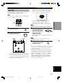
■ Rear center speaker
Place the rear center speaker in the center between the left
and right rear speakers at the same height from the floor
as the rear speakers.
■ Front effect speakers
Place the front effect speakers about 0.5 - 1 m (1 - 3 feet)
outside the main speakers and in front of the room, facing
slightly inwards, nearly 1.8 m (6 feet) above the floor.
■ Subwoofer
The position of the subwoofer is not so critical, because
low bass sounds are not highly directional. But it is better
to place the subwoofer near the main speakers. Turn it
slightly toward the center of the room to reduce the wall
reflections.
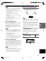
■ Main speakers
Place the left and right main speakers an equal distance
from the ideal listening position. The distance of each
speaker from each side of the video monitor should be the
same.
■ Center speaker
Align the front face of the center speaker with the front
face of your video monitor. Place the speaker as close to
the monitor as possible, such as directly over or under the
monitor and centrally between the main speakers.
■ Rear speakers
Place these speakers behind your listening position,
facing slightly inwards, nearly 1.8 m (6 feet) above the
floor.
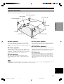
Speaker Placement
Refer to the following diagram when you place the speakers.
Main speaker (L)
1.8 m (6 feet)
Rear speaker (L)
Rear center speaker
Rear speaker (R)
Subwoofer
Main speaker (R)
Center speaker
Front effect speaker (R)
Front effect speaker (L)
Note
• If you do not use any effect speakers (rear, front effect, center and/or rear center), change the settings of SPEAKER SET items in the
SET MENU to designate the signals to other terminals you connect speakers to.
0103DSPAZ2_10-22_EN(GB) 02.8.22, 0:15 PM11

12
SPEAKER SETUP
12
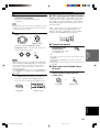
Connecting the Speakers
Be sure to connect the left channel (L), right channel (R), “+” (red) and “–” (black) properly. If the connections are
faulty, no sound will be heard from the speakers, and if the polarity of the speaker connections is incorrect, the sound
will be unnatural and lack bass.
CAUTION
• Use speakers with the specified impedance shown on the rear panel of this unit.
• Do not let the bare speaker wires touch each other and do not let them touch any metal part of this unit. This could
damage this unit and/or speakers.
If necessary, use the SET MENU to change the speaker mode settings according to the number and size of the speakers
in your configuration after you finish connecting your speakers.
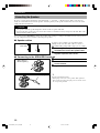
■ Speaker cables
A speaker cord is actually a pair of insulated cables
running side by side. One of the cables is colored or
shaped differently, perhaps with a stripe, groove or ridge.
1 Remove approximately 10 mm (3/8”) of
insulation from each of the speaker cables.
2 Twist the exposed wires of the cable
together to prevent short circuits.
■ Connecting to the SPEAKERS terminals
1 Unscrew the knob.
2 Insert one bare wire into the hole in the side
of each terminal.
3 Tighten the knob to secure the wire.
y
(For General and China models)
• Banana plug connections are also possible. First, tighten the
knob and then insert the banana plug connector into the end of
the corresponding terminal.
10 mm (3/8”)
Red: positive (+)
Black: negative (–)
Banana plug
3
1
2
0103DSPAZ2_10-22_EN(GB) 02.8.22, 0:15 PM12

13
English
INTRODUCTION
PREPARATION
BASIC OPERA-
TION
ADVANCED
OPERATION
ADDITIONAL
INFORMATION
APPENDIX
SPEAKER SETUP
AC OUTLETS
VOLTAGE
SELECTOR
SWITCHED
50W MAX. TOTAL
AC IN
CENTER
SUB
WOOFER
S VIDEO
MONITOR OUT
VIDEO
DIGITAL OUTPUT
DIGITAL
INPUT
6CH INPUT
GND
AUDIO AUDIO VIDEO
CONTROL
OUT
SPEAKERS
REMOTE
IN
OUT
1
2
RS-232C
+12V
15mA
MAX.
COMPONENT VIDEO
S VIDEO
DVD
D-TV
/LD
CBL
/SAT
VIDEO
P
R
DVD
MONITOR
OUT
CBL
/SAT
MAIN
IN
OUT
MAIN
REAR CENTER
(SURROUND)
FRONT
EFFECT
REAR
CENTER
REAR
CENTER
PRE OUT/MAIN IN
IMPEDANCE SELECTOR
SET BEFORE POWER ON
SUB
WOOFER
CENTER
REAR
FRONT EFFECT
REAR CENTER
P
B
Y
R
R
L
L
R
L
R
L
R
L
R
L
R
L
R
L
OPTICAL
OPTICAL
MD
/
TAPE
IN
(
PLAY
)
IN
(
PLAY
)
OUT
(
REC
)
OUT
(
REC
)
CD-R
CD-R
MD/TAPE
CD-R
DVD
CBL
/SAT
CD
CD
PHONO
IN
OUT
OUT
TUNER
VCR 2
/DVR
VCR 1
IN
MAIN
SURROUND
CD
D-TV
/LD
(SURROUND)
COAXIAL
+
–
–
+
+
–
–
+
+
–
–
+
+
–
–
+
+
–
–
+
REAR CENTER
A+B
REAR
8ΩMIN./
SPEAKER
8ΩMIN./
SPEAKER
8ΩMIN./
SPEAKER
8ΩMIN./
SPEAKER
8ΩMIN./
SPEAKER
16ΩMIN./
SPEAKER
CENTER
FRONT
MAIN A OR B
:
:
:
:
:
:
MAIN A OR B
FRONT
6ΩMIN./
SPEAKER
4ΩMIN./
SPEAKER
6ΩMIN./
SPEAKER
6ΩMIN./
SPEAKER
4ΩMIN./
SPEAKER
REAR CENTER
CENTER
REAR
:
:
:
:
:
A + B
8ΩMIN./
SPEAKER
:
A
B
Subwoofer
system
Rear Center
speaker
Rear speaker
Center
speaker
(General and China models)
Right Right Left
Front Effect speaker
Right Left
Left
Main B speaker
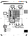
■ MAIN SPEAKERS terminals
One or two speaker systems can be connected to these terminals. If you use only one speaker system, connect it to either
of the MAIN A or B terminals.
■ REAR SPEAKERS terminals
A rear speaker system can be connected to these terminals.
■ CENTER SPEAKER terminals
A center speaker can be connected to these terminals.
■ REAR CENTER SPEAKER terminals
A rear center speaker can be connected to these terminals.
■ FRONT EFFECT SPEAKERS terminals
A front effect speaker system can be connected to these terminals.
■ SUBWOOFER jack
When using a subwoofer with built-in amplifier, including the YAMAHA Active Servo Processing Subwoofer System,
connect the input jack of the subwoofer system to this jack. Low bass signals distributed from the main, center and/or
rear channels are directed to this jack if they are assigned to this jack. (The cut-off frequency of this jack is 90 Hz.) The
LFE (low-frequency effect) signals generated when Dolby Digital or DTS is decoded are also directed if they are
assigned to this jack.
Note
• Depending on the settings of “1 SPEAKER SET” and “10 LFE LEVEL” on the SET MENU, some signals may not be output from
the SUBWOOFER jack.
Right Left
Main A speaker
0103DSPAZ2_10-22_EN(GB) 02.8.22, 0:15 PM13

14
SPEAKER SETUP
AC OUTLETS
VOLTAGE
SELECTOR
SWITCHED
50W MAX. TOTAL
AC IN
MAIN
(SURROUND)
FRONT
EFFECT
REAR
IMPEDANCE SELECTOR
SET BEFORE POWER ON
L
L
L
L
+
+
+
+
REAR CENTER
A+B
REAR
8ΩMIN./
SPEAKER
8ΩMIN./
SPEAKER
8ΩMIN./
SPEAKER
8ΩMIN./
SPEAKER
8ΩMIN./
SPEAKER
16ΩMIN./
SPEAKER
CENTER
FRONT
MAIN A OR B
:
:
:
:
:
:
MAIN A OR B
FRONT
6ΩMIN./
SPEAKER
4ΩMIN./
SPEAKER
6ΩMIN./
SPEAKER
6ΩMIN./
SPEAKER
4ΩMIN./
SPEAKER
REAR CENTER
CENTER
REAR
:
:
:
:
:
A + B
8ΩMIN./
SPEAKER
:
A
B
IMPEDANCE SELECTOR
SET BEFORE POWER ON
REAR CENTER
A+B
REAR
8ΩMIN./
SPEAKER
8ΩMIN./
SPEAKER
8ΩMIN./
SPEAKER
8ΩMIN./
SPEAKER
8ΩMIN./
SPEAKER
16ΩMIN./
SPEAKER
CENTER
FRONT
MAIN A OR B
:
:
:
:
:
:
MAIN A OR B
FRONT
6ΩMIN./
SPEAKER
4ΩMIN./
SPEAKER
6ΩMIN./
SPEAKER
6ΩMIN./
SPEAKER
4ΩMIN./
SPEAKER
REAR CENTER
CENTER
REAR
:
:
:
:
:
A + B
8ΩMIN./
SPEAKER
:
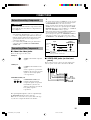
Switch
position
Upper
Lower
Speaker
Rear
Center
Center
Front
Effect
Rear
Main
Rear
Center
Center
Front
Effect
Rear
Main
Impedance level
The impedance must be 6 Ω or higher.
The impedance must be 4 Ω or higher.
The impedance of each speaker must be 6 Ω or higher.
The impedance of each speaker must be 6 Ω or higher.
If you use one set of main speakers, the impedance of
each speaker must be 4 Ω or higher.
If you use two sets of main speakers, the impedance of
each speaker must be 8 Ω or higher.
The impedance must be 8 Ω or higher.
The impedance must be 8 Ω or higher.
The impedance of each speaker must be 8 Ω or higher.
The impedance of each speaker must be 8 Ω or higher.
If you use one set of main speakers, the impedance of
each speaker must be 8 Ω or higher.
If you use two sets of main speakers, the impedance of
each speaker must be 16 Ω or higher.
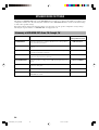
IMPEDANCE SELECTOR switch
■ IMPEDANCE SELECTOR switch
WARNING
Do not change the IMPEDANCE SELECTOR switch setting while the power of this unit is on, otherwise this unit
may be damaged.
If this unit fails to turn on when STANDBY/ON (or SYSTEM POWER) is pressed, the IMPEDANCE SELECTOR
switch may not be fully slid to either position. If so, slide the switch to either position fully when this unit is in the
standby mode.
Select the upper or lower position according to the impedance of the speakers in your system. Be sure to move this
switch only when this unit is in the standby mode.
(General and China models)
0103DSPAZ2_10-22_EN(GB) 02.8.22, 0:15 PM14

15
English
INTRODUCTION
PREPARATION
BASIC OPERA-
TION
ADVANCED
OPERATION
ADDITIONAL
INFORMATION
APPENDIX
y
• The signals input through the S VIDEO jacks can be converted
to composite signals inside of this unit and output through the
VIDEO MONITOR OUT jacks on this unit as well.
• (Europe and U.K. models only) The signals input through the
VIDEO jack on this unit can be output through the S VIDEO
MONITOR OUT jack by setting “V CONV.” in “13 DISPLAY
SET” on the SET MENU to ON (see page 65).
• When signals input through both S VIDEO and VIDEO jacks,
signals input through the S VIDEO jack has priority.
• You can designate the input for the COMPONENT VIDEO A
and B jacks according to your component by using “7 I/O
ASSIGNMENT” on the SET MENU (see page 62 for details).
■ VIDEO AUX jacks (on the front
panel)
These jacks are used to connect any video input source
such as a game console and a camcorder to this unit.
Before Connecting Components
CAUTION
Never connect this unit and other components to mains
power until all connections between components have
been completed.
• Be sure all connections are made correctly, that is to
say L (left) to L, R (right) to R, “+” to “+” and “–” to
“–”. Some components require different connection
methods and have different jack names. Refer to the
operation instructions for each component to be
connected to this unit.
• Use commercially available video pin cables when
connecting to the S VIDEO and COMPONENT
VIDEO jacks.
Connecting Video Components
■ About the video jacks
There are three types of video jacks.
VIDEO jacks transmit composite
signals.
S VIDEO jacks transmit S-video
signals.
S-video signals are separated into
luminance (Y) and color (C) video
signals to achieve high-quality
color reproduction.
COMPONENT VIDEO jacks
transmit component signals.
Component signals are separated
into luminance (Y) and color
difference (P
B , PR) to provide the
best quality in picture
reproduction.
The signal input through these jacks are output through
the MONITOR OUT jacks of the same type.
Make sure to connect the correct jacks of the same type
on your video component and the video monitor.
CONNECTIONS
VIDEO jack
S VIDEO jack
COMPONENT VIDEO jacks
VIDEO AUX
S VIDEO VIDEO AUDIO OPTICALLR
AUDIO OUT R
AUDIO OUT L
VIDEO OUT
OPTICAL OUT
S VIDEO OUT
O
V
L
R
S
COMPONENT VIDEO
PR PB Y
VIDEO
S VIDEO
Game
console or
video camera
S VIDEO
VIDEO
COMPONENT
VIDEO
Signal flow inside this unit
Only when “V CONV.” in “13 DISPLAY SET” on the
SET MENU.
(Europe and U.K. models only)
Input
Output
(MONITOR OUT)
0103DSPAZ2_10-22_EN(GB) 02.8.22, 0:15 PM15

16
CONNECTIONS
CENTER
SUB
WOOFER
S VIDEO
MONITOR OUT
VIDEO
DIGITAL OUTPUT
DIGITAL
INPUT
6CH INPUT
GND
AUDIO AUDIO VIDEO
CONTROL
OUT
REMOTE
IN
OUT
1
2
RS-232C
+12V
15mA
MAX.
COMPONENT VIDEO
S VIDEO
DVD
D-TV
/LD
CBL
/SAT
VIDEO
P
R
DVD
MONITOR
OUT
CBL
/SAT
MAIN
IN
OUT
PRE OUT/MAI
SUB
WOOFER
REAR
FRONT EFFE
C
REAR CENTER
P
B
Y
R
R
L
L
R
L
R
L
OPTICAL
OPTICAL
MD
/
TAPE
IN
(
PLAY
)
IN
(
PLAY
)
OUT
(
REC
)
OUT
(
REC
)
CD-R
CD-R
MD/TAPE
CD-R
DVD
CBL
/SAT
CD
CD
PHONO
IN
OUT
OUT
TUNER
VCR 2
/DVR
VCR 1
IN
MAIN
SURROUND
CD
D-TV
/LD
(SURROUND)
COAXIAL
V
S
L R
VVC
S S
L R
O
L
S
R
V
C
O
COMPONENT
INPUT
S VIDEO
INPUT
VIDEO
INPUT
S VIDEO
OUTPUT
VIDEO
OUTPUT
AUDIO OUTPUT
COAXIAL OUTPUT
OPTICAL OUTPUT
AUDIO OUTPUT
COMPONENT OUTPUT
VIDEO
OUTPUT
S VIDEO
OUTPUT
V V V
VVV
V
V
V
(General and China
models)
indicates S-video cables
indicates video cables
indicates coaxial cables
indicates optical cables
indicates right analog cables
indicates left analog cables
indicates signal direction
TV/digital TV or
LD player
DVD player
Video
monitor
indicates component video cables
0103DSPAZ2_10-22_EN(GB) 02.8.22, 0:15 PM16

17
English
INTRODUCTION
PREPARATION
BASIC OPERA-
TION
ADVANCED
OPERATION
ADDITIONAL
INFORMATION
APPENDIX
CONNECTIONS
CENTER
SUB
WOOFER
S VIDEO
MONITOR OUT
VIDEO
DIGITAL OUTPUT
DIGITAL
INPUT
6CH INPUT
GND
AUDIO AUDIO VIDEO
CONTROL
OUT
REMOTE
IN
OUT
1
2
RS-232C
+12V
15mA
MAX.
COMPONENT VIDEO
S VIDEO
DVD
D-TV
/LD
CBL
/SAT
VIDEO
P
R
DVD
MONITOR
OUT
CBL
/SAT
MAIN
IN
OUT
PRE OUT/MAI
SUB
WOOFER
REAR
FRONT EFFE
C
REAR CENTER
P
B
Y
R
R
L
L
R
L
R
L
OPTICAL
OPTICAL
MD
/
TAPE
IN
(
PLAY
)
IN
(
PLAY
)
OUT
(
REC
)
OUT
(
REC
)
CD-R
CD-R
MD/TAPE
CD-R
DVD
CBL
/SAT
CD
CD
PHONO
IN
OUT
OUT
TUNER
VCR 2
/DVR
VCR 1
IN
MAIN
SURROUND
CD
D-TV
/LD
(SURROUND)
COAXIAL
V
S
L R
VV
S S S
L R L R
O
S VIDEO OUTPUTVIDEO OUTPUT
AUDIO OUTPUT
OPTICAL OUTPUT
S VIDEO
INPUT
S VIDEO
OUTPUT
S VIDEO INPUT
VIDEO
OUTPUT
V
VIDEO
INPUT
AUDIO INPUT
AUDIO OUTPUT
VIDEO
INPUT
COMPONENT OUTPUT
V V V
VVV
L
S
R
V
O
COMPONENT
INPUT
V
V
V
indicates S-video cables
indicates video pin cables
indicates optical cables
indicates right audio pin cables
indicates left audio pin cables
indicates signal direction
Video
monitor
VCR 1 or VCR 2/
DVR (digital
video recorder)
Cable TV or
Satellite tuner
(General and China
models)
indicates component video cables
0103DSPAZ2_10-22_EN(GB) 02.8.22, 0:15 PM17

18
CONNECTIONS
Connecting Audio Components
■ Connecting a CD player
y
• The COAXIAL CD and OPTICAL CD jacks are available for a
CD player which has coaxial or optical digital output jacks.
• When you connect a CD player to both the COAXIAL CD and
OPTICAL CD jacks, priority is given to the input signals from
the COAXIAL CD jack.
■ Connecting an MD recorder, tape
deck or CD recorder
y
• DIGITAL OUTPUT jacks and analog OUT (REC) are
independent. Only digital signals are output from DIGITAL
OUTPUT jacks and analog signals from OUT (REC) jacks.
• When you connect your recording component to both the
analog and digital input jacks, the priority is given to the digital
signal.
Note
• When you connect a recording component to this unit, keep its
power on while using this unit. If the power is off, this unit may
distort the sound from other components.
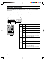
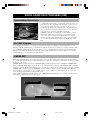
■ Connecting to digital jacks
This unit has digital jacks for direct transmission of
digital signals through either coaxial or fiber optic cables.
You can use the digital jacks to input PCM, Dolby Digital
and DTS bitstreams. When you connect components to
both the COAXIAL and OPTICAL jacks, priority is given
to the input signals from the COAXIAL jack. All digital
input jacks are acceptable for 96-kHz sampling digital
signals.
y
• You can designate the input for each digital jacks according to
your component by using “7 I/O ASSIGNMENT” on the SET
MENU (see page 62 for details).
About the dust protection cap
Pull out the cap from the optical jack before you connect
the fiber optic cable. Do not discard the cap. When you
are not using the optical jack, be sure to put the cap back
in place. This cap protects the jack from dust.
Notes
• DIGITAL OUTPUT jacks and analog OUT (REC) jacks are
independent. Only digital signals are output from DIGITAL
OUTPUT jacks and analog signals from OUT (REC) jacks.
• The OPTICAL jacks on this unit conform to the EIA standard.
If you use a fiber optic cable that does not conform to this
standard, this unit may not function properly.
■ Connecting a turntable
PHONO jacks are for connecting a turntable with an MM
or high-output MC cartridge. If you have a turntable with
a low-output MC cartridge, use an in-line boosting
transformer or MC-head amplifier when connecting to
these jacks.
y
• Connect your turntable to the GND terminal to reduce noise in
the signal. However you may hear less noise without the
connection to the GND terminal for some record players.
0103DSPAZ2_10-22_EN(GB) 02.8.22, 0:15 PM18
Pagina se încarcă...
Pagina se încarcă...
Pagina se încarcă...
Pagina se încarcă...
Pagina se încarcă...
Pagina se încarcă...
Pagina se încarcă...
Pagina se încarcă...
Pagina se încarcă...
Pagina se încarcă...
Pagina se încarcă...
Pagina se încarcă...
Pagina se încarcă...
Pagina se încarcă...
Pagina se încarcă...
Pagina se încarcă...
Pagina se încarcă...
Pagina se încarcă...
Pagina se încarcă...
Pagina se încarcă...
Pagina se încarcă...
Pagina se încarcă...
Pagina se încarcă...
Pagina se încarcă...
Pagina se încarcă...
Pagina se încarcă...
Pagina se încarcă...
Pagina se încarcă...
Pagina se încarcă...
Pagina se încarcă...
Pagina se încarcă...
Pagina se încarcă...
Pagina se încarcă...
Pagina se încarcă...
Pagina se încarcă...
Pagina se încarcă...
Pagina se încarcă...
Pagina se încarcă...
Pagina se încarcă...
Pagina se încarcă...
Pagina se încarcă...
Pagina se încarcă...
Pagina se încarcă...
Pagina se încarcă...
Pagina se încarcă...
Pagina se încarcă...
Pagina se încarcă...
Pagina se încarcă...
Pagina se încarcă...
Pagina se încarcă...
Pagina se încarcă...
Pagina se încarcă...
Pagina se încarcă...
Pagina se încarcă...
Pagina se încarcă...
Pagina se încarcă...
Pagina se încarcă...
Pagina se încarcă...
Pagina se încarcă...
Pagina se încarcă...
Pagina se încarcă...
Pagina se încarcă...
Pagina se încarcă...
Pagina se încarcă...
Pagina se încarcă...
Pagina se încarcă...
Pagina se încarcă...
Pagina se încarcă...
Pagina se încarcă...
Pagina se încarcă...
Pagina se încarcă...
Pagina se încarcă...
Pagina se încarcă...
Pagina se încarcă...
Pagina se încarcă...
Pagina se încarcă...
Pagina se încarcă...
Pagina se încarcă...
Pagina se încarcă...
Pagina se încarcă...
Pagina se încarcă...
Pagina se încarcă...
Pagina se încarcă...
Pagina se încarcă...
Pagina se încarcă...
Pagina se încarcă...
Pagina se încarcă...
Pagina se încarcă...
Pagina se încarcă...
Pagina se încarcă...
Pagina se încarcă...
Pagina se încarcă...
Pagina se încarcă...
Pagina se încarcă...
Pagina se încarcă...
Pagina se încarcă...
Pagina se încarcă...
Pagina se încarcă...
Pagina se încarcă...
Pagina se încarcă...
Pagina se încarcă...
Pagina se încarcă...
Pagina se încarcă...
Pagina se încarcă...
Pagina se încarcă...
Pagina se încarcă...
Pagina se încarcă...
Pagina se încarcă...
Pagina se încarcă...
Pagina se încarcă...
Pagina se încarcă...
Pagina se încarcă...
Pagina se încarcă...
Pagina se încarcă...
Pagina se încarcă...
Pagina se încarcă...
Pagina se încarcă...
Pagina se încarcă...
Pagina se încarcă...
Pagina se încarcă...
Pagina se încarcă...
Pagina se încarcă...
Pagina se încarcă...
Pagina se încarcă...
Pagina se încarcă...
Pagina se încarcă...
Pagina se încarcă...
Pagina se încarcă...
Pagina se încarcă...
Pagina se încarcă...
Pagina se încarcă...
Pagina se încarcă...
Pagina se încarcă...
Pagina se încarcă...
Pagina se încarcă...
Pagina se încarcă...
Pagina se încarcă...
Pagina se încarcă...
Pagina se încarcă...
Pagina se încarcă...
Pagina se încarcă...
Pagina se încarcă...
Pagina se încarcă...
Pagina se încarcă...
Pagina se încarcă...
Pagina se încarcă...
Pagina se încarcă...
Pagina se încarcă...
Pagina se încarcă...
Pagina se încarcă...
Pagina se încarcă...
Pagina se încarcă...
Pagina se încarcă...
Pagina se încarcă...
Pagina se încarcă...
Pagina se încarcă...
Pagina se încarcă...
Pagina se încarcă...
Pagina se încarcă...
Pagina se încarcă...
Pagina se încarcă...
Pagina se încarcă...
Pagina se încarcă...
Pagina se încarcă...
Pagina se încarcă...
Pagina se încarcă...
Pagina se încarcă...
Pagina se încarcă...
Pagina se încarcă...
Pagina se încarcă...
Pagina se încarcă...
Pagina se încarcă...
Pagina se încarcă...
Pagina se încarcă...
Pagina se încarcă...
Pagina se încarcă...
Pagina se încarcă...
Pagina se încarcă...
Pagina se încarcă...
Pagina se încarcă...
Pagina se încarcă...
Pagina se încarcă...
Pagina se încarcă...
Pagina se încarcă...
Pagina se încarcă...
Pagina se încarcă...
Pagina se încarcă...
Pagina se încarcă...
Pagina se încarcă...
Pagina se încarcă...
Pagina se încarcă...
Pagina se încarcă...
Pagina se încarcă...
Pagina se încarcă...
Pagina se încarcă...
Pagina se încarcă...
Pagina se încarcă...
Pagina se încarcă...
Pagina se încarcă...
Pagina se încarcă...
Pagina se încarcă...
Pagina se încarcă...
Pagina se încarcă...
Pagina se încarcă...
Pagina se încarcă...
Pagina se încarcă...
Pagina se încarcă...
Pagina se încarcă...
Pagina se încarcă...
Pagina se încarcă...
Pagina se încarcă...
Pagina se încarcă...
Pagina se încarcă...
Pagina se încarcă...
Pagina se încarcă...
Pagina se încarcă...
Pagina se încarcă...
Pagina se încarcă...
Pagina se încarcă...
Pagina se încarcă...
Pagina se încarcă...
Pagina se încarcă...
Pagina se încarcă...
Pagina se încarcă...
Pagina se încarcă...
Pagina se încarcă...
Pagina se încarcă...
Pagina se încarcă...
Pagina se încarcă...
Pagina se încarcă...
Pagina se încarcă...
Pagina se încarcă...
Pagina se încarcă...
Pagina se încarcă...
Pagina se încarcă...
Pagina se încarcă...
Pagina se încarcă...
Pagina se încarcă...
Pagina se încarcă...
Pagina se încarcă...
Pagina se încarcă...
Pagina se încarcă...
Pagina se încarcă...
Pagina se încarcă...
Pagina se încarcă...
Pagina se încarcă...
Pagina se încarcă...
Pagina se încarcă...
Pagina se încarcă...
Pagina se încarcă...
Pagina se încarcă...
Pagina se încarcă...
Pagina se încarcă...
Pagina se încarcă...
Pagina se încarcă...
Pagina se încarcă...
Pagina se încarcă...
Pagina se încarcă...
Pagina se încarcă...
Pagina se încarcă...
Pagina se încarcă...
Pagina se încarcă...
Pagina se încarcă...
Pagina se încarcă...
Pagina se încarcă...
Pagina se încarcă...
Pagina se încarcă...
Pagina se încarcă...
Pagina se încarcă...
Pagina se încarcă...
Pagina se încarcă...
Pagina se încarcă...
Pagina se încarcă...
Pagina se încarcă...
Pagina se încarcă...
Pagina se încarcă...
Pagina se încarcă...
Pagina se încarcă...
Pagina se încarcă...
Pagina se încarcă...
Pagina se încarcă...
Pagina se încarcă...
Pagina se încarcă...
Pagina se încarcă...
Pagina se încarcă...
Pagina se încarcă...
Pagina se încarcă...
Pagina se încarcă...
Pagina se încarcă...
Pagina se încarcă...
Pagina se încarcă...
Pagina se încarcă...
Pagina se încarcă...
Pagina se încarcă...
Pagina se încarcă...
Pagina se încarcă...
Pagina se încarcă...
Pagina se încarcă...
Pagina se încarcă...
Pagina se încarcă...
Pagina se încarcă...
Pagina se încarcă...
Pagina se încarcă...
Pagina se încarcă...
Pagina se încarcă...
Pagina se încarcă...
Pagina se încarcă...
Pagina se încarcă...
Pagina se încarcă...
Pagina se încarcă...
Pagina se încarcă...
Pagina se încarcă...
Pagina se încarcă...
Pagina se încarcă...
Pagina se încarcă...
Pagina se încarcă...
Pagina se încarcă...
Pagina se încarcă...
Pagina se încarcă...
Pagina se încarcă...
Pagina se încarcă...
Pagina se încarcă...
Pagina se încarcă...
Pagina se încarcă...
Pagina se încarcă...
Pagina se încarcă...
Pagina se încarcă...
Pagina se încarcă...
Pagina se încarcă...
Pagina se încarcă...
Pagina se încarcă...
Pagina se încarcă...
Pagina se încarcă...
Pagina se încarcă...
Pagina se încarcă...
Pagina se încarcă...
Pagina se încarcă...
Pagina se încarcă...
Pagina se încarcă...
Pagina se încarcă...
Pagina se încarcă...
Pagina se încarcă...
Pagina se încarcă...
Pagina se încarcă...
Pagina se încarcă...
Pagina se încarcă...
Pagina se încarcă...
Pagina se încarcă...
Pagina se încarcă...
Pagina se încarcă...
Pagina se încarcă...
Pagina se încarcă...
Pagina se încarcă...
Pagina se încarcă...
Pagina se încarcă...
Pagina se încarcă...
Pagina se încarcă...
Pagina se încarcă...
Pagina se încarcă...
Pagina se încarcă...
Pagina se încarcă...
Pagina se încarcă...
Pagina se încarcă...
Pagina se încarcă...
Pagina se încarcă...
Pagina se încarcă...
Pagina se încarcă...
Pagina se încarcă...
Pagina se încarcă...
Pagina se încarcă...
Pagina se încarcă...
Pagina se încarcă...
Pagina se încarcă...
Pagina se încarcă...
Pagina se încarcă...
Pagina se încarcă...
Pagina se încarcă...
Pagina se încarcă...
Pagina se încarcă...
Pagina se încarcă...
Pagina se încarcă...
Pagina se încarcă...
Pagina se încarcă...
Pagina se încarcă...
Pagina se încarcă...
Pagina se încarcă...
Pagina se încarcă...
Pagina se încarcă...
Pagina se încarcă...
Pagina se încarcă...
Pagina se încarcă...
Pagina se încarcă...
Pagina se încarcă...
Pagina se încarcă...
Pagina se încarcă...
Pagina se încarcă...
Pagina se încarcă...
Pagina se încarcă...
Pagina se încarcă...
Pagina se încarcă...
Pagina se încarcă...
Pagina se încarcă...
Pagina se încarcă...
Pagina se încarcă...
Pagina se încarcă...
Pagina se încarcă...
Pagina se încarcă...
Pagina se încarcă...
Pagina se încarcă...
Pagina se încarcă...
Pagina se încarcă...
Pagina se încarcă...
Pagina se încarcă...
Pagina se încarcă...
Pagina se încarcă...
Pagina se încarcă...
Pagina se încarcă...
Pagina se încarcă...
Pagina se încarcă...
Pagina se încarcă...
Pagina se încarcă...
Pagina se încarcă...
Pagina se încarcă...
Pagina se încarcă...
Pagina se încarcă...
Pagina se încarcă...
Pagina se încarcă...
Pagina se încarcă...
Pagina se încarcă...
Pagina se încarcă...
Pagina se încarcă...
Pagina se încarcă...
Pagina se încarcă...
Pagina se încarcă...
Pagina se încarcă...
Pagina se încarcă...
Pagina se încarcă...
Pagina se încarcă...
Pagina se încarcă...
Pagina se încarcă...
Pagina se încarcă...
Pagina se încarcă...
Pagina se încarcă...
Pagina se încarcă...
Pagina se încarcă...
Pagina se încarcă...
Pagina se încarcă...
Pagina se încarcă...
Pagina se încarcă...
Pagina se încarcă...
Pagina se încarcă...
Pagina se încarcă...
Pagina se încarcă...
Pagina se încarcă...
Pagina se încarcă...
Pagina se încarcă...
Pagina se încarcă...
Pagina se încarcă...
Pagina se încarcă...
Pagina se încarcă...
Pagina se încarcă...
Pagina se încarcă...
Pagina se încarcă...
Pagina se încarcă...
Pagina se încarcă...
Pagina se încarcă...
Pagina se încarcă...
Pagina se încarcă...
Pagina se încarcă...
Pagina se încarcă...
Pagina se încarcă...
Pagina se încarcă...
Pagina se încarcă...
Pagina se încarcă...
Pagina se încarcă...
Pagina se încarcă...
Pagina se încarcă...
Pagina se încarcă...
Pagina se încarcă...
Pagina se încarcă...
Pagina se încarcă...
Pagina se încarcă...
Pagina se încarcă...
Pagina se încarcă...
Pagina se încarcă...
Pagina se încarcă...
Pagina se încarcă...
Pagina se încarcă...
Pagina se încarcă...
Pagina se încarcă...
Pagina se încarcă...
Pagina se încarcă...
Pagina se încarcă...
Pagina se încarcă...
Pagina se încarcă...
Pagina se încarcă...
Pagina se încarcă...
Pagina se încarcă...
Pagina se încarcă...
Pagina se încarcă...
Pagina se încarcă...
Pagina se încarcă...
Pagina se încarcă...
Pagina se încarcă...
Pagina se încarcă...
Pagina se încarcă...
Pagina se încarcă...
Pagina se încarcă...
Pagina se încarcă...
Pagina se încarcă...
Pagina se încarcă...
Pagina se încarcă...
Pagina se încarcă...
Pagina se încarcă...
Pagina se încarcă...
Pagina se încarcă...
Pagina se încarcă...
Pagina se încarcă...
Pagina se încarcă...
Pagina se încarcă...
Pagina se încarcă...
Pagina se încarcă...
Pagina se încarcă...
Pagina se încarcă...
Pagina se încarcă...
Pagina se încarcă...
Pagina se încarcă...
Pagina se încarcă...
Pagina se încarcă...
Pagina se încarcă...
Pagina se încarcă...
Pagina se încarcă...
Pagina se încarcă...
Pagina se încarcă...
Pagina se încarcă...
Pagina se încarcă...
Pagina se încarcă...
Pagina se încarcă...
Pagina se încarcă...
Pagina se încarcă...
Pagina se încarcă...
Pagina se încarcă...
Pagina se încarcă...
Pagina se încarcă...
Pagina se încarcă...
Pagina se încarcă...
Pagina se încarcă...
Pagina se încarcă...
Pagina se încarcă...
Pagina se încarcă...
Pagina se încarcă...
Pagina se încarcă...
Pagina se încarcă...
Pagina se încarcă...
Pagina se încarcă...
Pagina se încarcă...
-
 1
1
-
 2
2
-
 3
3
-
 4
4
-
 5
5
-
 6
6
-
 7
7
-
 8
8
-
 9
9
-
 10
10
-
 11
11
-
 12
12
-
 13
13
-
 14
14
-
 15
15
-
 16
16
-
 17
17
-
 18
18
-
 19
19
-
 20
20
-
 21
21
-
 22
22
-
 23
23
-
 24
24
-
 25
25
-
 26
26
-
 27
27
-
 28
28
-
 29
29
-
 30
30
-
 31
31
-
 32
32
-
 33
33
-
 34
34
-
 35
35
-
 36
36
-
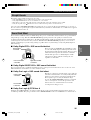 37
37
-
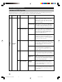 38
38
-
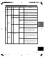 39
39
-
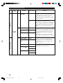 40
40
-
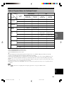 41
41
-
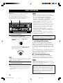 42
42
-
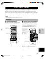 43
43
-
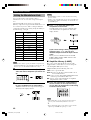 44
44
-
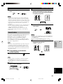 45
45
-
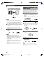 46
46
-
 47
47
-
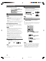 48
48
-
 49
49
-
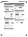 50
50
-
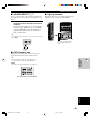 51
51
-
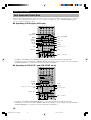 52
52
-
 53
53
-
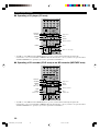 54
54
-
 55
55
-
 56
56
-
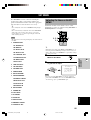 57
57
-
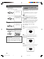 58
58
-
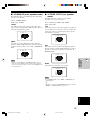 59
59
-
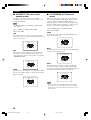 60
60
-
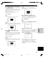 61
61
-
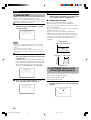 62
62
-
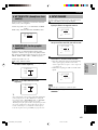 63
63
-
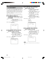 64
64
-
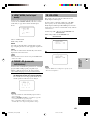 65
65
-
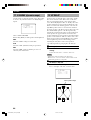 66
66
-
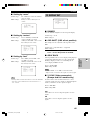 67
67
-
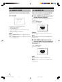 68
68
-
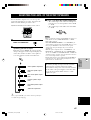 69
69
-
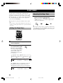 70
70
-
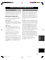 71
71
-
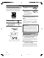 72
72
-
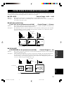 73
73
-
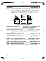 74
74
-
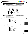 75
75
-
 76
76
-
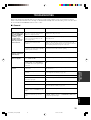 77
77
-
 78
78
-
 79
79
-
 80
80
-
 81
81
-
 82
82
-
 83
83
-
 84
84
-
 85
85
-
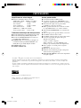 86
86
-
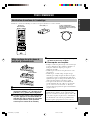 87
87
-
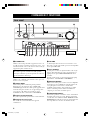 88
88
-
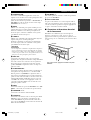 89
89
-
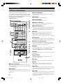 90
90
-
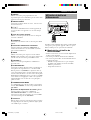 91
91
-
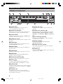 92
92
-
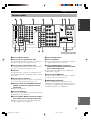 93
93
-
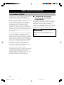 94
94
-
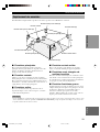 95
95
-
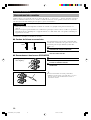 96
96
-
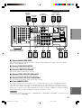 97
97
-
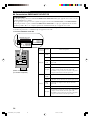 98
98
-
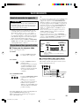 99
99
-
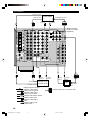 100
100
-
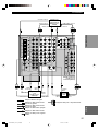 101
101
-
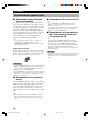 102
102
-
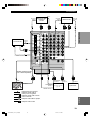 103
103
-
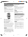 104
104
-
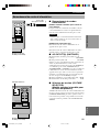 105
105
-
 106
106
-
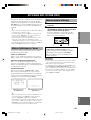 107
107
-
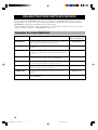 108
108
-
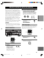 109
109
-
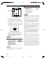 110
110
-
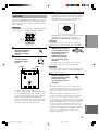 111
111
-
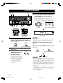 112
112
-
 113
113
-
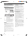 114
114
-
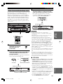 115
115
-
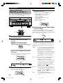 116
116
-
 117
117
-
 118
118
-
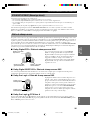 119
119
-
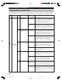 120
120
-
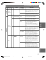 121
121
-
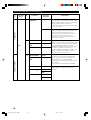 122
122
-
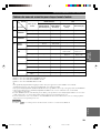 123
123
-
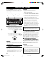 124
124
-
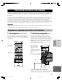 125
125
-
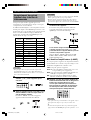 126
126
-
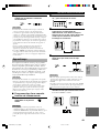 127
127
-
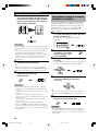 128
128
-
 129
129
-
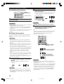 130
130
-
 131
131
-
 132
132
-
 133
133
-
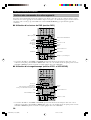 134
134
-
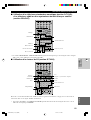 135
135
-
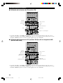 136
136
-
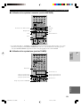 137
137
-
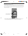 138
138
-
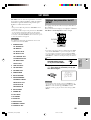 139
139
-
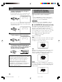 140
140
-
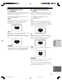 141
141
-
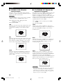 142
142
-
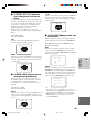 143
143
-
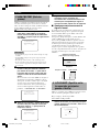 144
144
-
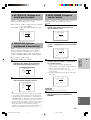 145
145
-
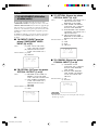 146
146
-
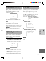 147
147
-
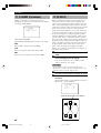 148
148
-
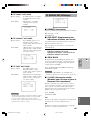 149
149
-
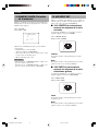 150
150
-
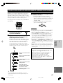 151
151
-
 152
152
-
 153
153
-
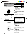 154
154
-
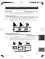 155
155
-
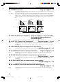 156
156
-
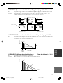 157
157
-
 158
158
-
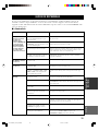 159
159
-
 160
160
-
 161
161
-
 162
162
-
 163
163
-
 164
164
-
 165
165
-
 166
166
-
 167
167
-
 168
168
-
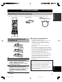 169
169
-
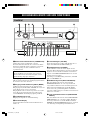 170
170
-
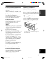 171
171
-
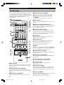 172
172
-
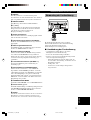 173
173
-
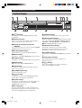 174
174
-
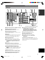 175
175
-
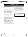 176
176
-
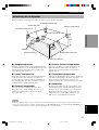 177
177
-
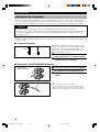 178
178
-
 179
179
-
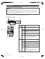 180
180
-
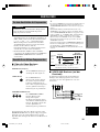 181
181
-
 182
182
-
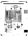 183
183
-
 184
184
-
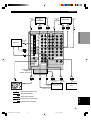 185
185
-
 186
186
-
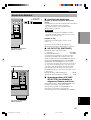 187
187
-
 188
188
-
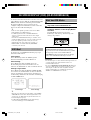 189
189
-
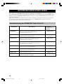 190
190
-
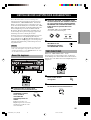 191
191
-
 192
192
-
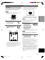 193
193
-
 194
194
-
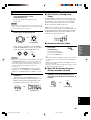 195
195
-
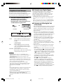 196
196
-
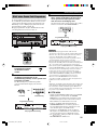 197
197
-
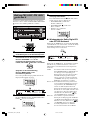 198
198
-
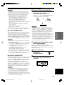 199
199
-
 200
200
-
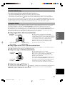 201
201
-
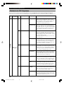 202
202
-
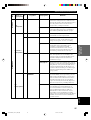 203
203
-
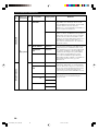 204
204
-
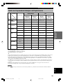 205
205
-
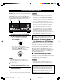 206
206
-
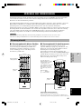 207
207
-
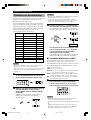 208
208
-
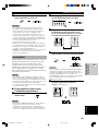 209
209
-
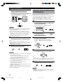 210
210
-
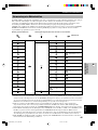 211
211
-
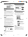 212
212
-
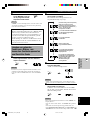 213
213
-
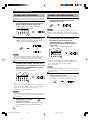 214
214
-
 215
215
-
 216
216
-
 217
217
-
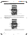 218
218
-
 219
219
-
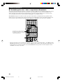 220
220
-
 221
221
-
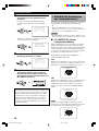 222
222
-
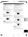 223
223
-
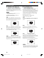 224
224
-
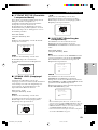 225
225
-
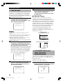 226
226
-
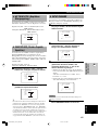 227
227
-
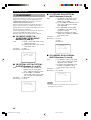 228
228
-
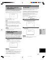 229
229
-
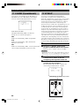 230
230
-
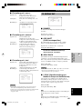 231
231
-
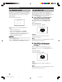 232
232
-
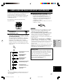 233
233
-
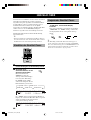 234
234
-
 235
235
-
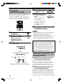 236
236
-
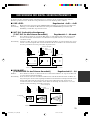 237
237
-
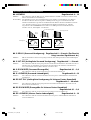 238
238
-
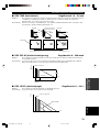 239
239
-
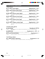 240
240
-
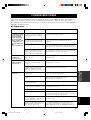 241
241
-
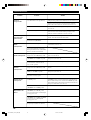 242
242
-
 243
243
-
 244
244
-
 245
245
-
 246
246
-
 247
247
-
 248
248
-
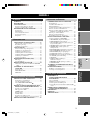 249
249
-
 250
250
-
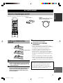 251
251
-
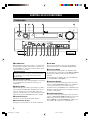 252
252
-
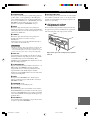 253
253
-
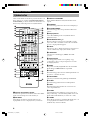 254
254
-
 255
255
-
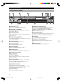 256
256
-
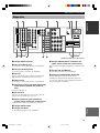 257
257
-
 258
258
-
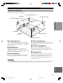 259
259
-
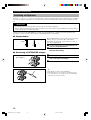 260
260
-
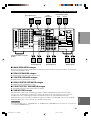 261
261
-
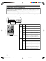 262
262
-
 263
263
-
 264
264
-
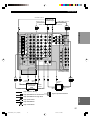 265
265
-
 266
266
-
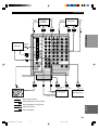 267
267
-
 268
268
-
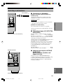 269
269
-
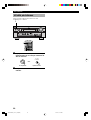 270
270
-
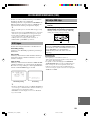 271
271
-
 272
272
-
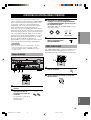 273
273
-
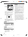 274
274
-
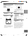 275
275
-
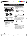 276
276
-
 277
277
-
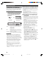 278
278
-
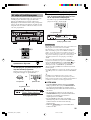 279
279
-
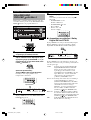 280
280
-
 281
281
-
 282
282
-
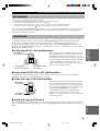 283
283
-
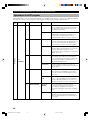 284
284
-
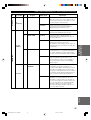 285
285
-
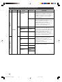 286
286
-
 287
287
-
 288
288
-
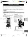 289
289
-
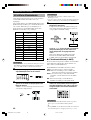 290
290
-
 291
291
-
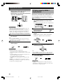 292
292
-
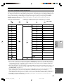 293
293
-
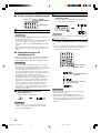 294
294
-
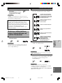 295
295
-
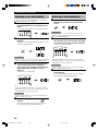 296
296
-
 297
297
-
 298
298
-
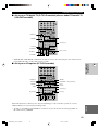 299
299
-
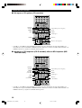 300
300
-
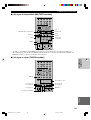 301
301
-
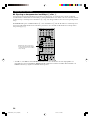 302
302
-
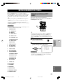 303
303
-
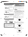 304
304
-
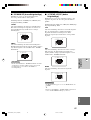 305
305
-
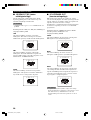 306
306
-
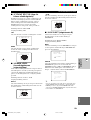 307
307
-
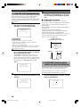 308
308
-
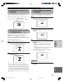 309
309
-
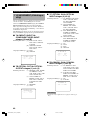 310
310
-
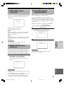 311
311
-
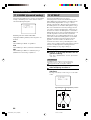 312
312
-
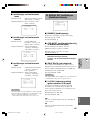 313
313
-
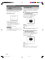 314
314
-
 315
315
-
 316
316
-
 317
317
-
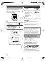 318
318
-
 319
319
-
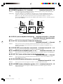 320
320
-
 321
321
-
 322
322
-
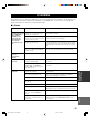 323
323
-
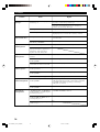 324
324
-
 325
325
-
 326
326
-
 327
327
-
 328
328
-
 329
329
-
 330
330
-
 331
331
-
 332
332
-
 333
333
-
 334
334
-
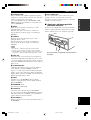 335
335
-
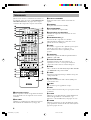 336
336
-
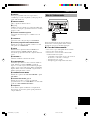 337
337
-
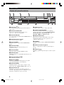 338
338
-
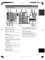 339
339
-
 340
340
-
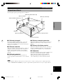 341
341
-
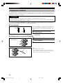 342
342
-
 343
343
-
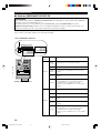 344
344
-
 345
345
-
 346
346
-
 347
347
-
 348
348
-
 349
349
-
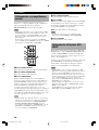 350
350
-
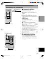 351
351
-
 352
352
-
 353
353
-
 354
354
-
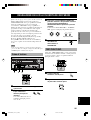 355
355
-
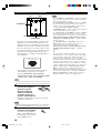 356
356
-
 357
357
-
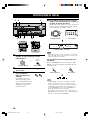 358
358
-
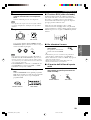 359
359
-
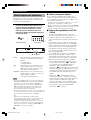 360
360
-
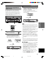 361
361
-
 362
362
-
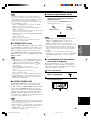 363
363
-
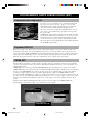 364
364
-
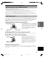 365
365
-
 366
366
-
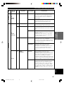 367
367
-
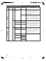 368
368
-
 369
369
-
 370
370
-
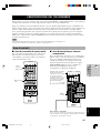 371
371
-
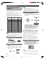 372
372
-
 373
373
-
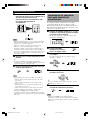 374
374
-
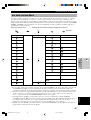 375
375
-
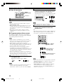 376
376
-
 377
377
-
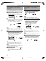 378
378
-
 379
379
-
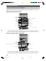 380
380
-
 381
381
-
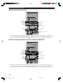 382
382
-
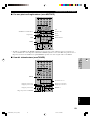 383
383
-
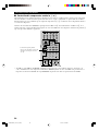 384
384
-
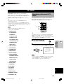 385
385
-
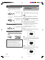 386
386
-
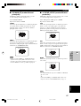 387
387
-
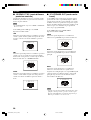 388
388
-
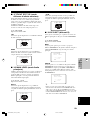 389
389
-
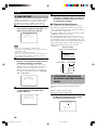 390
390
-
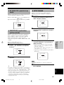 391
391
-
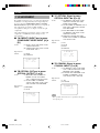 392
392
-
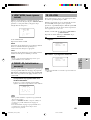 393
393
-
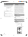 394
394
-
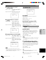 395
395
-
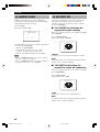 396
396
-
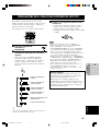 397
397
-
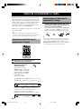 398
398
-
 399
399
-
 400
400
-
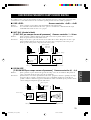 401
401
-
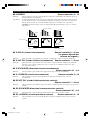 402
402
-
 403
403
-
 404
404
-
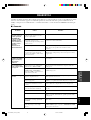 405
405
-
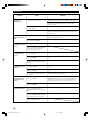 406
406
-
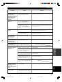 407
407
-
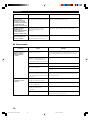 408
408
-
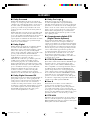 409
409
-
 410
410
-
 411
411
-
 412
412
-
 413
413
-
 414
414
-
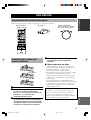 415
415
-
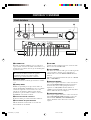 416
416
-
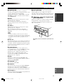 417
417
-
 418
418
-
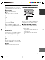 419
419
-
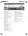 420
420
-
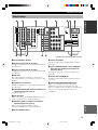 421
421
-
 422
422
-
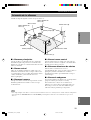 423
423
-
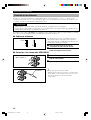 424
424
-
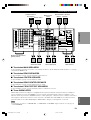 425
425
-
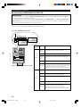 426
426
-
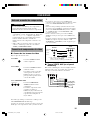 427
427
-
 428
428
-
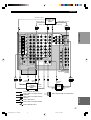 429
429
-
 430
430
-
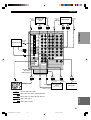 431
431
-
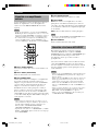 432
432
-
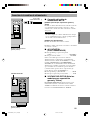 433
433
-
 434
434
-
 435
435
-
 436
436
-
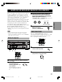 437
437
-
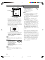 438
438
-
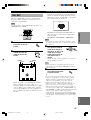 439
439
-
 440
440
-
 441
441
-
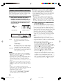 442
442
-
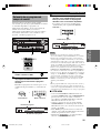 443
443
-
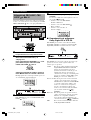 444
444
-
 445
445
-
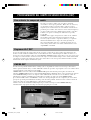 446
446
-
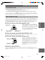 447
447
-
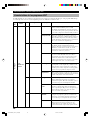 448
448
-
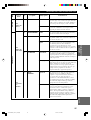 449
449
-
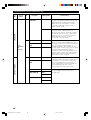 450
450
-
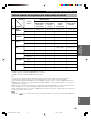 451
451
-
 452
452
-
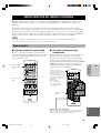 453
453
-
 454
454
-
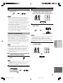 455
455
-
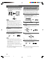 456
456
-
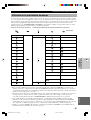 457
457
-
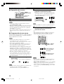 458
458
-
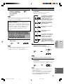 459
459
-
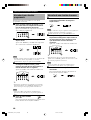 460
460
-
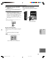 461
461
-
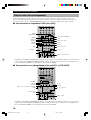 462
462
-
 463
463
-
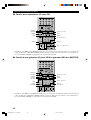 464
464
-
 465
465
-
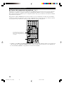 466
466
-
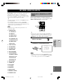 467
467
-
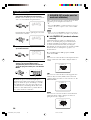 468
468
-
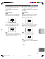 469
469
-
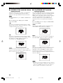 470
470
-
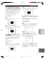 471
471
-
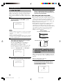 472
472
-
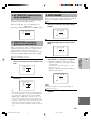 473
473
-
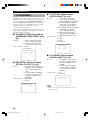 474
474
-
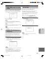 475
475
-
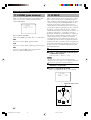 476
476
-
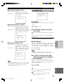 477
477
-
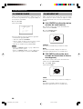 478
478
-
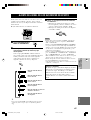 479
479
-
 480
480
-
 481
481
-
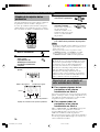 482
482
-
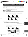 483
483
-
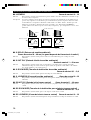 484
484
-
 485
485
-
 486
486
-
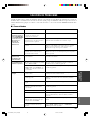 487
487
-
 488
488
-
 489
489
-
 490
490
-
 491
491
-
 492
492
-
 493
493
-
 494
494
-
 495
495
-
 496
496
-
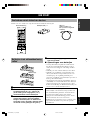 497
497
-
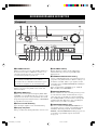 498
498
-
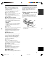 499
499
-
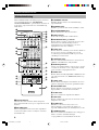 500
500
-
 501
501
-
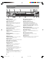 502
502
-
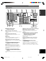 503
503
-
 504
504
-
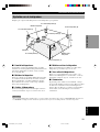 505
505
-
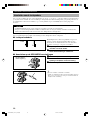 506
506
-
 507
507
-
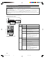 508
508
-
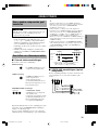 509
509
-
 510
510
-
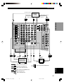 511
511
-
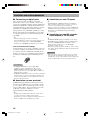 512
512
-
 513
513
-
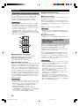 514
514
-
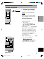 515
515
-
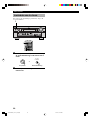 516
516
-
 517
517
-
 518
518
-
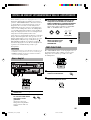 519
519
-
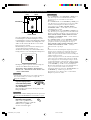 520
520
-
 521
521
-
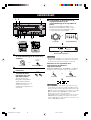 522
522
-
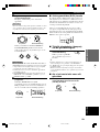 523
523
-
 524
524
-
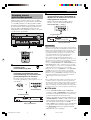 525
525
-
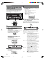 526
526
-
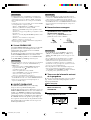 527
527
-
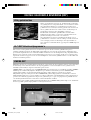 528
528
-
 529
529
-
 530
530
-
 531
531
-
 532
532
-
 533
533
-
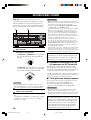 534
534
-
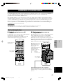 535
535
-
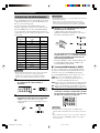 536
536
-
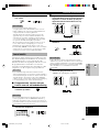 537
537
-
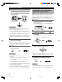 538
538
-
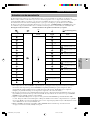 539
539
-
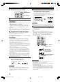 540
540
-
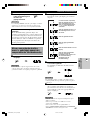 541
541
-
 542
542
-
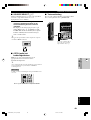 543
543
-
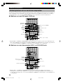 544
544
-
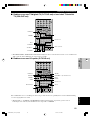 545
545
-
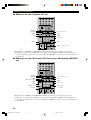 546
546
-
 547
547
-
 548
548
-
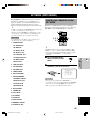 549
549
-
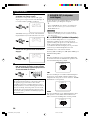 550
550
-
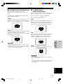 551
551
-
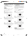 552
552
-
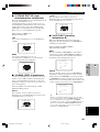 553
553
-
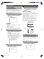 554
554
-
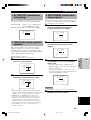 555
555
-
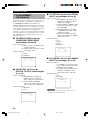 556
556
-
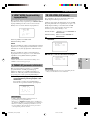 557
557
-
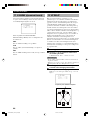 558
558
-
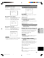 559
559
-
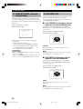 560
560
-
 561
561
-
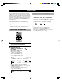 562
562
-
 563
563
-
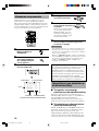 564
564
-
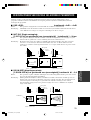 565
565
-
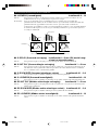 566
566
-
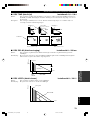 567
567
-
 568
568
-
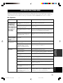 569
569
-
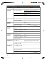 570
570
-
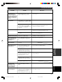 571
571
-
 572
572
-
 573
573
-
 574
574
-
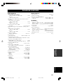 575
575
-
 576
576


Yamaha DSP-AZ2 Manualul proprietarului
- Categorie
- Receptor
- Tip
- Manualul proprietarului
în alte limbi
- Türkçe: Yamaha DSP-AZ2 El kitabı
- français: Yamaha DSP-AZ2 Le manuel du propriétaire
- English: Yamaha DSP-AZ2 Owner's manual
- Deutsch: Yamaha DSP-AZ2 Bedienungsanleitung
- italiano: Yamaha DSP-AZ2 Manuale del proprietario
- español: Yamaha DSP-AZ2 El manual del propietario
- svenska: Yamaha DSP-AZ2 Bruksanvisning
- dansk: Yamaha DSP-AZ2 Brugervejledning
- Nederlands: Yamaha DSP-AZ2 de handleiding