Maestro 42.586.74 Instrucțiuni de utilizare
- Categorie
- Burghiu electric
- Tip
- Instrucțiuni de utilizare
Acest manual este potrivit și pentru

42.586.74 11021
Original operating instructions
Hammer Drill
Originalbetriebsanleitung
Schlagbohrmaschine
Instrucţiuni de utilizare originale
Maşină de găurit cu percuţie
Orijinal Kullanma Talimatı
Darbeli Matkap
MID


5
GB

Important!
When using equipment, a few safety precautions
must be observed to avoid injuries and damage.
Please read the complete operating manual with due
care. Keep this manual in a safe place, so that the
information is available at all times. If you give the
equipment to any other person, give them these
operating instructions as well.
We accept no liability for damage or accidents which
arise due to non-observance of these instructions
and the safety information.
1. Safety regulations
The corresponding safety information can be found
in the enclosed booklet.
CAUTION!
Read all safety regulations and instructions.
Any errors made in following the safety regulations
and instructions may result in an electric shock, fire
and/or serious injury.
Keep all safety regulations and instructions in a
safe place for future use.
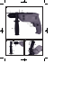
2. Layout (Fig. 1)
1. Drill chuck
2. Drill depth stop
3. Drill/hammer drill selector switch
4. Locking button
5. ON/OFF switch
6. Speed controller
7. Clockwise/Counter-clockwise switch
8. Additional handle
3. Proper use
The drill is designed for drilling holes into wood, iron,
non-ferrous metals and rock using the appropriate
bits.
The equipment is to be used only for its prescribed
purpose. Any other use is deemed to be a case of
misuse. The user / operator and not the
manufacturer will be liable for any damage or injuries
of any kind caused as a result of this.
Please note that our equipment has not been
designed for use in commercial, trade or industrial
applications. Our warranty will be voided if the
machine is used in commercial, trade or industrial
businesses or for equivalent purposes.
4. Technical data
Mains voltage: 230 V ~ 50 Hz
Power input: 650 W
-1
Idling speed: 0-2800 min
Drilling capacity Concrete 13 mm
Steel 10 mm
Wood 30 mm
Protection class: II /
Weight: 1.8 kg
Sound and vibration
Sound and vibration values were measured in
accordance with EN 60745.
LpA sound pressure level 92.5 dB(A)
KpA uncertainty 3 dB
LWA sound power level 103.5 dB(A)
KWA uncertainty 3 dB
Wear ear-muffs.
The impact of noise can cause damage to hearing.
Total vibration values (vector sum of three directions)
determined in accordance with EN 60745.
Hammer drilling in concrete
Vibration emission value ah= 9.99 m/s2
K uncertainty = 1.5 m/s2
Drilling in metal
Vibration emission value ah≤ 2.5 m/s2
K uncertainty = 1.5 m/s2
6
GB

5. Before starting the equipment
Before you connect the equipment to the mains
supply make sure that the data on the rating plate
are identical to the mains data.
Always pull the power plug before making
adjustments to the equipment.
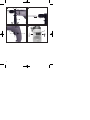
5.1. Fitting the additional handle (Fig. 2-3/Item 8)
The additional handle (8) enables you to achieve
better stability whilst using the hammer drill. Do not
use the tool without the additional handle.
The additional handle (8) is secured to the hammer
drill by a clamp. During the handle clockwise tightens
this clamp. Turning it anti-clockwise will release the
clamp.
The supplied additional handle (8) must first be
fitted. To do this, the clamp must be opened by
turning the handle until it is wide enough for the
additional handle to be slid over the chuck (1)
and on to the hammer drill.
After you have positioned the additional handle
(8), turn it to the most comfortable working
position for you.
Now turn the handle in the opposite direction
again until the additional handle is secure.
The additional handle (8) is suitable for both left-
handed and right-handed users.
5.2 Fitting and adjusting the depth stop
(Fig. 4/Item 2)
The depth stop (2) is held in place by the additional
handle (8) by clamping. The clamp can be released
and tightened by turning the handle.
Release the clamp and fit the depth stop (2) in
the recess provided for it in the additional handle.
Set the depth stop (2) to the same level as the
drill bit.
Pull the depth stop back by the required drilling
depth.
Turn the handle on the additional handle (8) until
it is secure.
Now drill the hole until the depth stop (2) touches
the workpiece.
Additional information for electric power tools
Warning!
The specified vibration value was established in
accordance with a standardized testing method. It
may change according to how the electric equipment
is used and may exceed the specified value in
exceptional circumstances.
The specified vibration value can be used to compare
the equipment with other electric power tools.
The specified vibration value can be used for initial
assessment of a harmful effect.
Keep the noise emissions and vibrations to a
minimum.
· Only use appliances which are in perfect
working order.
· Service and clean the appliance regularly.
· Adapt your working style to suit the appliance.
· Do not overload the appliance.
· Have the appliance serviced whenever
necessary.
· Switch the appliance off when it is not in use.
· Wear protective gloves.
Residual risks
Even if you use this electric power tool in
accordance with instructions, certain residual
risks cannot be rules out. The following hazards
may arise in connection with the equipment's
construction and layout:
1. Lung damage if no suitable protective dust
mask is used.
2. Damage to hearing if no suitable ear protection
is used.
3. Health damage caused by hand-arm vibrations
if the equipment is used over a prolonged
period or is not properly guided and
maintained.
GB
7

You avoid drilling messy holes (for example in
tiles).
6.3 Preselecting the speed (Fig. 6/Item 6)
The speed setting ring (6) enables you to define
the maximum speed. The ON/OFF switch (5) can
only be pressed to the defined maximum speed
setting.
Set the speed using the setting ring (6) on the
ON/OFF switch (5).
Do not attempt to make this setting whilst the drill
is in use.
6.4 Clockwise/Counter-clockwise switch
(Fig. 6/Item 7)
Change switch position only when the drill is
at a standstill!
Switch the direction of the hammer drill using the
clockwise/counter-clockwise switch (7):
Direction Switch position
Clockwise (forwards and drill) R
Counter-clockwise (reverse) L
6.5 Drill / hammer drill selector switch
(Fig. 7/Item 3)
Change switch position only when the drill is
at a standstill!
Drill
Drill / hammer drill selector switch (3) in the drill
position. (Position A)
Use for: Wood, metal, plastic
Hammer drill
Drill / hammer drill selector switch (3) in the hammer
drill position. (Position B)
Use for: Concrete, rock, masonry
6.6 Tips for working with your hammer drill
6.6.1 Drilling concrete and masonry
Switch the Drill/Hammer drill selector switch (3)
to position B (Hammer drill).
Always use carbide drill bits and a high speed
setting for drilling into masonry and concrete.
6.6.2 Drilling steel
Switch the drill / hammer drill selector switch (3)
to position A (drill).
Always use HSS drill bits (HSS = high speed
steel) and a low speed setting for drilling steel.
We recommend that you lubricate the hole with a
suitable cutting fluid to prevent unnecessary drill
bit wear.
5.3 Fitting the drill bit (Fig. 5)
Always pull the power plug before making
adjustments to the equipment.
Release the depth stop (2) as described in 5.2
and push it towards the additional handle. This
provides free access to the chuck (1).
This hammer drill is fitted with a keyless chuck
(1).
Open the chuck (1). The drill bit opening must be
large enough to fit the drill bit into.
Select a suitable drill bit. Push the drill bit as far
as possible into the chuck opening.
Close the chuck (1). Check that the drill bit is
secure in the chuck (1).
Check at regular intervals that the drill bit or tool
is secure (pull the mains plug).
6. Operation
6.1 ON/OFF switch (Fig. 6/Item 5)
First fit a suitable drill bit into the tool (see 5.3).
Connect the mains plug to a suitable socket.
Position the drill in the position you wish to drill.
To switch on:
Press the ON/OFF switch (5)
Continuous operation:
Secure the ON/OFF switch (5) with the locking
button (4).
To switch off:
Press the ON/OFF switch (5) briefly.
6.2 Adjusting the speed (Fig. 6/Item 5)
You can infinitely vary the speed whilst using the
tool.
Select the speed by applying a greater or lesser
pressure to the ON/OFF switch (5).
Select the correct speed: The most suitable
speed depends on the workpiece, the type of use
and the drill bit used.
Low pressure on the ON/OFF switch (5): Lower
speed (suitable for: small screws and soft
materials)
Greater pressure on the ON/OFF switch (5):
Higher speed (suitable for large/long screws and
hard materials)
Tip: Start drilling holes at low speed. Then increase
the speed in stages.
Benefits:
The drill bit is easier to control when starting the
hole and will not slide away.
8
GB

8.4 Ordering replacement parts:
Please quote the following data when ordering
replacement parts:
Type of machine
Article number of the machine
Identification number of the machine
Replacement part number of the part required
For our latest prices and information please go to
www.isc-gmbh.info
9. Disposal and recycling
The unit is supplied in packaging to prevent its being
damaged in transit. This packaging is raw material
and can therefore be reused or can be returned to
the raw material system.
The unit and its accessories are made of various
types of material, such as metal and plastic.
Defective components must be disposed of as
special waste. Ask your dealer or your local council.
10. Storage
Store the equipment and accessories out of children's
reach in a dark and dry place at above freezing
temperature. The ideal storage temperature is
between 5 and 30 °C. Store the electric tool in its
original packaging.
6.6.3 Inserting/Removing screws
Switch the Drill/Hammer drill selector switch (3)
to position A (drill).
Use a low speed setting
6.6.4 Starting holes
If you wish to drill a deep hole in a hard material
(such as steel), we recommend that you start the
hole with a smaller drill bit.
6.6.5 Drilling tiles
To start the hole, switch the drill / hammer drill
selector switch (3) to position A (drill).
Switch the drill / hammer drill selector switch (3)
to position B (hammer drill) as soon as the drill
bit has passed through the tiles.
7. Replacing the power cable
If the power cable for this equipment is damaged, it
must be replaced by the manufacturer or its after-
sales service or similarly trained personnel to avoid
danger.
8. Cleaning, maintenance and
ordering of spare parts
Always pull out the mains power plug before starting
any cleaning work.
8.1 Cleaning
Keep all safety devices, air vents and the motor
housing free of dirt and dust as far as possible.
Wipe the equipment with a clean cloth or blow it
with compressed air at low pressure.
We recommend that you clean the device
immediately each time you have finished using it.
Clean the equipment regularly with a moist cloth
and some soft soap. Do not use cleaning agents
or solvents; these could attack the plastic parts of
the equipment. Ensure that no water can seep
into the device.
8.2 Carbon brushes
In case of excessive sparking, have the carbon
brushes checked only by a qualified electrician.
Important! The carbon brushes should not be rep
laced by anyone but a qualified electrician.
8.3 Maintenance
There are no parts inside the equipment which
require additional maintenance.
GB
9

“WARNUNG - Zur Verringerung des Verletzungsrisikos Bedienungsanleitung lesen”
Tragen Sie einen Gehörschutz.
Die Einwirkung von Lärm kann Gehörverlust bewirken.
Tragen Sie eine Staubschutzmaske.
Beim Bearbeiten von Holz und anderer Materialien kann gesundheitsschädlicher Staub
entstehen. Asbesthaltiges Material darf nicht bearbeitet werden!
Tragen Sie eine Schutzbrille.
Während der Arbeit entstehende Funken oder aus dem Gerät heraustretende Splitter, Späne
und Stäube können Sichtverlust bewirken.
10
D

Achtung!
Beim Benutzen von Geräten müssen einige
Sicherheitsvorkehrungen eingehalten werden, um
Verletzungen und Schäden zu verhindern. Lesen Sie
diese Bedienungsanleitung / Sicherheitshinweise
deshalb sorgfältig durch. Bewahren Sie diese gut
auf, damit Ihnen die Informationen jederzeit zur
Verfügung stehen. Falls Sie das Gerät an andere
Personen übergeben sollten, händigen Sie diese
Bedienungsanleitung / Sicherheitshinweise bitte mit
aus. Wir übernehmen keine Haftung für Unfälle oder
Schäden, die durch Nichtbeachten dieser Anleitung
und den Sicherheitshinweisen entstehen.
1. Sicherheitshinweise
Die entsprechenden Sicherheitshinweise finden Sie
im beiliegenden Heftchen!
WARNUNG
Lesen Sie alle Sicherheitshinweise und
Anweisungen. Versäumnisse bei der Einhaltung der
Sicherheitshinweise und Anweisungen können
elektrischen Schlag, Brand und/oder schwere
Verletzungen verursachen zur Folge haben.
Bewahren Sie alle Sicherheitshinweise und
Anweisungen für die Zukunft auf.
2. Gerätebeschreibung (Bild 1)
1. Bohrfutter
2. Bohrtiefenanschlag
3. Bohren-/Schlagbohren-Umschalter
4. Feststellknopf
5. Ein-/Ausschalter
6. Drehzahl-Einstellring
7. Rechts-/Linkslauf-Umschalter
8. Zusatzhandgriff
3. Bestimmungsgemäße Verwendung
Die Bohrmaschine ist zum Bohren von Löchern in
Holz, Eisen, Buntmetallen und Gestein unter
Verwendung des entsprechenden Bohrwerkzeugs
ausgelegt.
Die Maschine darf nur nach ihrer Bestimmung
verwendet werden. Jede weitere darüber
hinausgehende Verwendung ist nicht
bestimmungsgemäß. Für daraus hervorgerufene
Schäden oder Verletzungen aller Art haftet der
Benutzer/Bediener und nicht der Hersteller.
Bitte beachten Sie, dass unsere Geräte
bestimmungsgemäß nicht für den gewerblichen,
handwerklichen oder industriellen Einsatz konstruiert
wurden. Wir übernehmen keine Gewährleistung,
wenn das Gerät in Gewerbe-, Handwerks- oder
Industriebetrieben sowie bei gleichzusetzenden
Tätigkeiten eingesetzt wird.
4. Technische Daten
Netzspannung: 230 V ~ 50 Hz
Leistungsaufnahme: 650 W
Leerlauf-Drehzahl: 0-2800 min-1
Bohrleistung: Beton 13 mm
Stahl 10 mm
Holz 30 mm
Schutzklasse: II /
Gewicht: 1,8 kg
Geräusch und Vibration
Die Geräusch- und Vibrationswerte wurden entspre-
chend EN 60745 ermittelt.
Schalldruckpegel LpA 92,5 dB(A)
Unsicherheit KpA 3 dB
Schallleistungspegel LWA 103,5 dB(A)
Unsicherheit KWA 3 dB
Tragen Sie einen Gehörschutz.
Die Einwirkung von Lärm kann Gehörverlust bewir-
ken.
Schwingungsgesamtwerte (Vektorsumme dreier
Richtungen) ermittelt entsprechend EN 60745.
Schlagbohren in Beton
Schwingungsemissionswert ah= 9,99 m/s2
Unsicherheit K = 1,5 m/s2
Bohren in Metall
Schwingungsemissionswert ah≤ 2,5 m/s2
Unsicherheit K = 1,5 m/s2
DD
11

D
5. Vor Inbetriebnahme
Überzeugen Sie sich vor dem Anschließen, dass die
Daten auf dem Typenschild mit den Netzdaten
übereinstimmen.
Ziehen Sie immer den Netzstecker, bevor Sie
Einstellungen am Gerät vornehmen.
5.1. Zusatzhandgriff montieren (Bild 2-3/Pos. 8)
Der Zusatzhandgriff (8) bietet Ihnen während der
Benutzung der Schlagbohrmaschine zusätzlichen
Halt. Benutzen Sie das Gerät daher nicht ohne den
Zusatzhandgriff.
Befestigt wird der Zusatzhandgriff (8) an der
Schlagbohrmaschine durch Klemmung. Durch
drehen des Griffes im Uhrzeigersinn wird die
Klemmung angezogen. Drehen gegen den
Uhrzeigersinn löst die Klemmung.
Der beiliegende Zusatzhandgriff (8) muss
zunächst montiert werden. Hierzu ist durch
Drehen des Griffes die Klemmung weit genug zu
öffnen, damit der Zusatzhandgriff über das
Bohrfutter (1) auf die Schlagbohrmaschine
geschoben werden kann.
Nach dem Aufschieben des Zusatzhandgriffes
(8) schwenken Sie diesen in die für Sie
angenehmste Arbeitsposition.
Jetzt den Griff in entgegengesetzter Drehrichtung
wieder zudrehen, bis der Zusatzhandgriff fest
sitzt.
Der Zusatzhandgriff (8) ist für Rechtshänder
ebenso wie für Linkshänder geeignet.
5.2 Tiefenanschlag montieren und einstellen
(Bild 4/Pos. 2)
Der Tiefenanschlag (2) wird vom Zusatzhandgriff (8)
durch Klemmung gehalten. Die Klemmung wird
wieder durch Drehen des Griffes gelöst bzw.
festgezogen.
Lösen Sie die Klemmung und setzen Sie den
Tiefenanschlag (2) in die dafür vorgesehene
Aussparung des Zusatzhandgriffes ein.
Bringen Sie den Tiefenanschlag (2) auf gleiche
Ebene zum Bohrer.
Ziehen Sie den Tiefenanschlag um die
gewünschte Bohrtiefe zurück.
Drehen Sie den Griff des Zusatzhandgriffes (8)
wieder zu bis dieser fest sitzt.
Bohren Sie nun das Loch, bis der Tiefenanschlag
(2) das Werkstück berührt.
Zusätzliche Informationen für Elektrowerkzeuge
Warnung!
Der angegebene Schwingungsemissionswert ist nach
einem genormten Prüfverfahren gemessen worden
und kann sich, abhängig von der Art und Weise, in
der das Elektrowerkzeug verwendet wird, ändern
und in Ausnahmefällen über dem angegebenen
Wert liegen.
Der angegebene Schwingungsemissionswert kann
zum Vergleich eines Elektrowerkzeuges mit einem
anderen verwendet werden.
Der angegebene Schwingungsemissionswert kann
auch zu einer einleitenden Einschätzung der
Beeinträchtigung verwendet werden.
Beschränken Sie die Geräuschentwicklung und
Vibration auf ein Minimum!
· Verwenden Sie nur einwandfreie Geräte.
· Passen Sie Ihre Arbeitsweise dem Gerät an.
· Überlasten Sie das Gerät nicht.
· Warten und reinigen Sie das Gerät regelmäßig.
· Lassen Sie das Gerät gegebenenfalls
überprüfen.
· Schalten Sie das Gerät aus, wenn es nicht
benutzt wird.
· Tragen Sie Handschuhe.
Restrisiken
Auch wenn Sie dieses Elektrowerkzeug
vorschriftsmäßig bedienen, bleiben immer
Restrisiken bestehen. Folgende Gefahren
können im Zusammenhang mit der Bauweise und
Ausführung dieses Elektrowerkzeuges auftreten:
1. Lungenschäden, falls keine geeignete
Staubschutzmaske getragen wird.
2. Gehörschäden, falls kein geeigneter Gehörschutz
getragen wird.
3. Gesundheitsschäden, die aus Hand-Arm-
Schwingungen resultieren, falls das Gerät über
einen längeren Zeitraum verwendet wird oder
nicht ordnungsgemäß geführt und gewartet wird.
12
D

Tipp: Bohren Sie Bohrlöcher mit geringer Drehzahl
an. Erhöhen Sie Die Drehzahl danach schrittweise.
Vorteile:
Der Bohrer ist beim Anbohren leichter zu
kontrollieren und rutscht nicht ab.
Sie vermeiden zersplitterte Bohrlöcher (z.B. bei
Kacheln).
6.3 Vorwählen der Drehzahl (Bild 6/Pos. 6)
Der Drehzahl-Einstellring (6) ermöglicht es Ihnen,
die maximale Drehzahl zu definieren. Der Ein-
/Ausschalter (5) kann nur noch bis zur
vorgegebenen Maximaldrehzahl eingedrückt
werden.
Stellen Sie die Drehzahl mit dem Einstellring (6)
im Ein-/Ausschalter (5) ein.
Nehmen Sie diese Einstellung nicht während des
Bohrens vor.
6.4 Rechts-/Linkslauf-Umschalter (Bild 6/Pos. 7)
Nur im Stillstand umschalten!
Stellen Sie mit dem Rechts-/Linkslauf-
Umschalter (7) die Laufrichtung des
Schlagbohrers ein:
Laufrichtung Schalterposition
Rechtslauf (Vorwärts und Bohren) R
Linkslauf (Rücklauf) L
6.5 Bohren/Schlagbohren-Umschalter
(Bild 7/Pos. 3)
Nur im Stillstand umschalten!
Bohren:
Bohren-/Schlagbohren-Umschalter (3) in Stellung
Bohren. (Position A)
Anwendung: Hölzer; Metalle; Kunststoffe
Schlagbohren:
Bohren-/Schlagbohren-Umschalter (3) in Stellung
Schlagbohren. (Position B)
Anwendung: Beton; Gestein; Mauerwerk
6.6 Tipps für das Arbeiten mit Ihrer
Schlagbohrmaschine
6.6.1 Bohren von Beton und Mauerwerk
Stellen Sie den Bohren/Schlagbohren
Umschalter (3) auf die Position B
(Schlagbohren).
Benutzen Sie für das Bearbeiten von Mauerwerk
oder Beton immer Hartmetallbohrer und eine
hohe Drehzahleinstellung.
5.3 Einsetzen des Bohrers (Bild 5)
Ziehen Sie immer den Netzstecker, bevor Sie
Einstellungen am Gerät vornehmen.
Tiefenanschlag (2) wie in 5.2 beschrieben lösen
und in Richtung Bohrergriff schieben. Somit hat
man freien Zugang zum Bohrfutter (1).
Diese Schlagbohrmaschine ist mit einem
Schnellspann-Bohrfutter (1) ausgestattet.
Drehen Sie das Bohrfutter (1) auf. Die
Bohreröffnung muss groß genug sein, um den
Bohrer aufzunehmen.
Wählen Sie einen geeigneten Bohrer aus.
Schieben Sie das Werkzeug soweit wie möglich
in die Bohrfutteröffnung hinein.
Drehen Sie das Bohrfutter (1) zu. Prüfen Sie, ob
der Bohrer fest im Bohrfutter (1) sitzt.
Überprüfen Sie in regelmäßigen Abständen den
festen Sitzt des Bohrers bzw. Werkzeuges
(Netzstecker ziehen!).
6. Bedienung
6.1 Ein/Ausschalter (Bild 6/Pos. 5)
Setzen Sie zuerst einen geeigneten Bohrer in
das Gerät ein (siehe 5.3).
Verbinden Sie den Netzstecker mit einer
geeigneten Steckdose.
Setzen Sie die Bohrmaschine direkt an der
Bohrstelle an.
Einschalten:
Ein-/Ausschalter (5) drücken
Dauerbetrieb:
Ein-/Ausschalter (5) mit Feststellknopf (4) sichern.
Ausschalten:
Ein-/Ausschalter (5) kurz eindrücken.
6.2 Drehzahl einstellen (Bild 6/Pos. 5)
Sie können die Drehzahl während des Betriebes
stufenlos steuern.
Durch mehr oder wenig starkes Drücken des Ein-
/Ausschalters (5) wählen Sie die Drehzahl.
Wahl der richtigen Drehzahl: Die am besten
geeignete Drehzahl ist abhängig vom Werkstück,
von der Betriebsart und vom eingesetzten
Bohrer.
Geringer Druck auf Ein-/Ausschalter (5):
niedrigere Drehzahl (Geeignet für: kleine
Schrauben, weiche Werkstoffe)
Größerer Druck auf Ein-/Ausschalter (5): höhere
Drehzahl (Geeignet für: große/lange Schrauben,
harte Werkstoffe)
D
13

feuchten Tuch und etwas Schmierseife.
Verwenden Sie keine Reinigungs- oder
Lösungsmittel; diese könnten die Kunststoffteile
des Gerätes angreifen. Achten Sie darauf, dass
kein Wasser in das Geräteinnere gelangen kann.
8.2 Kohlebürsten
Bei übermäßiger Funkenbildung lassen Sie die
Kohlebürsten durch eine Elektrofachkraft überprüfen.
Achtung! Die Kohlebürsten dürfen nur von einer
Elektrofachkraft ausgewechselt werden.
8.3 Wartung
Im Geräteinneren befinden sich keine weiteren zu
wartenden Teile.
8.4 Ersatzteilbestellung:
Bei der Ersatzteilbestellung sollten folgende
Angaben gemacht werden;
Typ des Gerätes
Artikelnummer des Gerätes
Ident-Nummer des Gerätes
Ersatzteilnummer des erforderlichen Ersatzteils
Aktuelle Preise und Infos finden Sie unter
www.isc-gmbh.info
9. Entsorgung und Wiederverwertung
Das Gerät befindet sich in einer Verpackung um
Transportschäden zu verhindern. Diese Verpackung
ist Rohstoff und ist somit wieder verwendbar oder
kann dem Rohstoffkreislauf zurückgeführt werden.
Das Gerät und dessen Zubehör bestehen aus
verschiedenen Materialien, wie z.B. Metall und
Kunststoffe. Führen Sie defekte Bauteile der
Sondermüllentsorgung zu. Fragen Sie im
Fachgeschäft oder in der Gemeindeverwaltung nach!
10. Lagerung
Lagern Sie das Gerät und dessen Zubehör an einem
dunklen, trockenen und frostfreiem sowie für Kinder
unzugänglichem Ort. Die optimale Lagertemperatur
liegt zwischen 5 und 30 ˚C. Bewahren Sie das
Elektrowerkzeug in der Originalverpackung auf.
6.6.2 Bohren von Stahl
Stellen Sie den Bohren/Schlagbohren
Umschalter (3) auf die Position A (Bohren).
Benutzen Sie für das Bearbeiten von Stahl immer
HSS-Bohrer (HSS = Hochlegierter
Schnellarbeitsstahl) und eine niedrige
Drehzahleinstellung.
Es ist empfehlenswert die Bohrung durch ein
geeignetes Kühlmittel zu schmieren um
unnötigen Bohrerverschleiß zu vermeiden.
6.6.3 Schrauben eindrehen/lösen
Stellen Sie den Bohren/Schlagbohren
Umschalter (3) auf die Position A (Bohren).
Benutzen Sie eine niedrige Drehzahleinstellung.
6.6.4 Löcher anbohren
Falls Sie ein tiefes Loch in ein hartes Material (wie
etwa Stahl) bohren möchten, empfehlen wir, dass Sie
das Loch mit einem kleineren Bohrer vorbohren.
6.6.5 Bohren in Fliesen und Kacheln
Stellen Sie zum Anbohren den Umschalter
Bohren/Schlagbohren (3) auf die Position A
(Bohren).
Stellen Sie den Umschalter
Bohren/Schlagbohren (3) auf die Position B
(Schlagbohren), sobald der Bohrer die
Fliese/Kachel durchschlagen hat.
7. Austausch der Netzanschlussleitung
Wenn die Netzanschlussleitung dieses Gerätes
beschädigt wird, muss sie durch den Hersteller oder
seinen Kundendienst oder eine ähnlich qualifizierte
Person ersetzt werden, um Gefährdungen zu
vermeiden.
8. Reinigung, Wartung und
Ersatzteilbestellung
Ziehen Sie vor allen Reinigungsarbeiten den
Netzstecker.
8.1 Reinigung
Halten Sie Schutzvorrichtungen, Luftschlitze und
Motorengehäuse so staub- und schmutzfrei wie
möglich. Reiben Sie das Gerät mit einem
sauberen Tuch ab oder blasen Sie es mit
Druckluft bei niedrigem Druck aus.
Wir empfehlen, dass Sie das Gerät direkt nach
jeder Benutzung reinigen.
Reinigen Sie das Gerät regelmäßig mit einem
14
D

ş şş
ş
15
RO

Atenţie!
La utilizarea aparatelor trebuie respectate câteva
măsuri de siguranţă, pentru a evita accidentele şi
daunele. De aceea, citiţi cu grijă instrucţiunile de
utilizare/indicaţiile de siguranţă. Păstraţi aceste
materiale în bune condiţii, pentru ca aceste informaţii
să fie disponibile în orice moment. Dacă predaţi
aparatul altor persoane, înmânaţi-le şi aceste
instrucţiuni de utilizare /indicaţii de siguranţă. Nu ne
asumăm nici o răspundere pentru accidente sau
daune care rezultă din nerespectarea acestor
instrucţiuni de utilizare şi a indicaţiilor de siguranţă.
1. Indicaţii de siguranţå
Indicaţiile de siguranţå aferente le gåsiţi în broµura
anexatå.
AVERTIZARE!
Citiţi indicaţiile de siguranţă şi îndrumările.
Nerespectarea indicaţiilor de siguranţă şi a
îndrumărilor poate avea ca urmare electrocutare,
incendiu şi/sau răniri grave.
Păstraţi pentru viitor toate indicaţiile de
siguranţă şi îndrumările.
2. Descrierea aparatului (vezi Figura 1)
1. Mandrină
2. Opritor adâncime de găurire
3. Comutator găurire / percuţie
4. Buton de fixare
5. Întrerupător pornire/oprire
6. Reglor al turaţiei
7. Comutator rotire stânga/dreapta
8. Mâner suplimentar
3. Utilizarea conform scopului
Maşina de găurit este construită pentru găurirea
lemnului, fierului, a metalelor neferoase şi a pietrei cu
utilizarea sculelor de găurit corespunzătoare.
Maşina se va utiliza numai conform scopului pentru
care este concepută. Orice altă utilizare nu este în
conformitate cu scopul. Pentru pagubele sau
vătămările rezultate în acest caz este responsabil
utilizatorul/operatorul şi nu producătorul.
Vă rugăm să ţineţi cont de faptul că maşinile noastre
nu sunt construite pentru utilizare în domeniile
meşteşugăreşti şi industriale. Noi nu preluăm nici o
garanţie atunci când aparatul este folosit în
întreprinderile meşteşugăreşti sau industriale ori în
scopuri similare.
4. Date tehnice
Tensiunea de reţea: 230 V~ 50 Hz
Puterea consumată: 650 W
-1
Turaţie la mers în gol: 0-2800 min
Capacitatea de găurire: Beton 13 mm
Oţel 10 mm
Lemn 30 mm
Clasa de protecţie: II/
Greutate: 1,8 kg
Zgomote şi vibraţii
Valorile nivelelor de zgomot şi de vibraţie au fost
calculate conform EN 60745.
Nivelul presiunii sonore L 92,5 dB (A)
pA
Nesiguranţă K 3 dB
pA
Nivelul capacităţii sonore L 103,5 dB (A)
WA
Nesiguranţă K 3 dB
WA
Purtaţi protecţie antifonică.
Expunerea la zgomot poate cauza deteriorarea sau
pierderea auzului.
Valorile totale ale nivelului de vibraţii (suma vectorială
a trei direcţii), calculate conform EN 60745.
Găurire prin percuţie în beton
2
Valoare a vibraţiilor emise a = 9,99 m/s
h
2
Nesiguranţă K = 1,5 m/s
Găurire în metal
2
Valoare a vibraţiilor emise a ≤ 2,5 m/s
h
2
Nesiguranţă K = 1,5 m/s
RO
16

5. Înainte de punerea în funcţiune
Asiguraţi-vă înainte de racordare că datele de pe
plăcuţa de identificare corespund datelor din reţea.
Scoateţi întotdeauna ştecherul din priză înainte de a
executa reglaje la maşină.
5.1.Montarea mânerului suplimentar
(Fig. 2-3/Poz. 8)
Mânerul suplimentar (8) vă oferă stabilitate
suplimentară în timpul utilizării maşinii de găurit cu
percuţie. Din acest motiv nu folosiţi maşina fără
mânerul suplimentar.
Fixarea mânerului suplimentar (8) la maşina de găurit
cu percuţie se face cu ajutorul clemelor. Prin rotirea
mânerului în sens orar se strâng clemele. Prin rotirea
în sens antiorar se desface fixarea mânerului.
Mânerul suplimentar anexat (8) trebuie mai întâi
montat. Pentru aceasta trebuie ca prin rotirea
mânerului să deschideţi clemele suficient de mult
pentru ca mânerul suplimentar să poată fi împins
peste mandrină (1) pe maşina de găurit prin
percuţie.
După poziţionarea mânerului suplimentar (8)
potriviţi-l în poziţia de lucru cea mai comodă
pentru Dvs..
Rotiţi acum mânerul în sensul opus, până când
se blochează.
Mânerul suplimentar (8) este indicat atât pentru
dreptaci cât şi pentru stângaci.
5.2 Montarea şi reglarea opritorului adâncimii de
găurire (Fig. 4/Poz. 2)
Opritorul adâncimii de găurire (2) este susţinut de
către mânerul suplimentar (8) cu ajutorul clemelor.
Clemele se deschid şi respectiv închid prin rotirea
mânerului.
Deschideţi clemele şi introduceţi opritorul
adâncimii de găurire (2) în lăcaşul special
prevăzut pe mânerul suplimentar.
Aduceţi opritorul adâncimii de găurire (2) la
acelaşi nivel cu burghiul.
Trageţi opritorul cu exact adâncimea de găurire
dorită înapoi.
Rotiţi mânerul suplimentar (8) la loc, până când
se blochează din nou.
Daţi acum o gaură şi înaintaţi până când opritorul
adâncimii de găurire (2) atinge piesa prelucrată.
5.3 Montarea burghiului (Fig 5)
Scoateţi întotdeauna ştecherul din priză înainte
de a efectua reglaje ale aparatului.
Desfaceţi opritorul adâncimii de găurire (2)
conform descrierii de la punctul 5.2 şi împingeţi-l
în direcţia mânerului. Aveţi acum acces liber la
Informaţii suplimentare pentru scule electrice
Avertisment!
Valoarea vibraţiilor emise a fost măsurată conform
unui proces de verificare normat şi se poate modifica
in funcţie de modul de utilizare a sculei electrice şi in
cazuri excepţionale poate depăşi valoarea indicată.
Valoarea vibraţiilor emise poate fi utilizată pentru
comparaţia cu vibraţiile sculelor electrice ale altor
producători.
Valoarea vibraţiilor poate fi utilizată şi la o estimare
introductivă a afecţiunii aparatului.
Limitaţi zgomotul şi vibraţiile la un nivel minim.
· Utilizaţi numai aparate in stare ireproşabilă.
· Intreţineţi şi curăţaţi aparatul cu regularitate.
· Adaptaţi modul dvs. de lucru aparatului.
· Nu suprasolicitaţi aparatul.
· Dacă este necesar, lăsaţi aparatul să fie
verificat.
· Decuplaţi aparatul, atunci cand acesta nu este
utilizat.
· Purtaţi mănuşi!
Riscuri reziduale
Riscurile reziduale nu pot fi eliminate complet,
chiar dacă manipulaţi această sculă electrică in
mod regulamentar. Următoarele pericole pot
apărea, dependente de tipul constructiv şi
execuţia acestei scule electrice:
1. Afecţiuni pulmonare, in cazul in care nu se poartă
mască de protecţie impotriva prafului adecvată.
2. Afecţiuni auditive, in cazul in care nu se poartă
protecţie antifonică corespunzătoare.
3. Afecţiuni ale sănătăţii rezultate din vibraţia
manăbraţ, in cazul utilizării timp mai indelungat a
aparatului sau a utilizării şi intreţinerii sale
necorespunzătoare.
17
RO

Evitaţi astfel găurile aşchiate (de ex. la plăcile de
teracotă).
6.3 Preselecţia turaţiei (Fig. 6/Poz. 6)
Inelul de reglare a turaţiei (6) vă permite definirea
turaţiei maxime. Întrerupătorul de pornire/oprire
(5) nu mai poate fi apăsat decât până la turaţia
maximă prestabilită.
Alegeţi turaţia maximă cu ajutorul inelului de
reglare a turaţiei (6) aflat în dreptul
întrerupătorului de pornire/oprire (5).
Nu efectuaţi acest reglaj în timpul procesului de
găurire.
6.4 Comutatorul rotire stânga/dreapta
(Fig. 6/Poz. 7)
Comutarea se va realiza numai când aparatul
este în repaus!
Alegeţi sensul de lucru al maşinii de găurit prin
percuţie cu ajutorul comutatorului rotire spre
stânga/rotire spre dreapta (7):
Sensul de lucru al maşinii Poziţia comutatorului
Rotaţie spre dreapta (înainte şi găurire) R
Rotaţie spre stânga (înapoi) L
6.5 Comutator găurire/percuţie (Fig. 7/Poz. 3)
Comutarea se va realiza numai când aparatul
este în repaus!
Găurire:
Comutatorul găurire/percuţie (3) este în poziţia
găurire. (Poziţia A)
Utilizare: lemn; metale; materiale plastice
Găurire prin percuţie:
Comutatorul găurire/percuţie (3) este în poziţia
percuţie. (Poziţia B)
Utilizare: beton; piatră; zidărie
6.6 Ponturi pentru lucrul cu maşina de găurit cu
percuţie
6.6.1 Găurire în beton şi zidărie
Poziţionaţi comutatorul găurire/percuţie (3) în
poziţia B (găurire prin percuţie).
În cazul zidăriei sau al betonului utilizaţi
întotdeauna burghie pentru metale dure şi o
turaţie ridicată.
6.6.2 Găurire în oţel
Poziţionaţi comutatorul găurire/percuţie (3) în
poziţia A (găurire).
În cazul oţelului utilizaţi întotdeauna burghie HSS
(HSS = oţel rapid, înalt aliat) şi o turaţie joasă.
RO
mandrină (1).
Această maşină de găurit prin percuţie este
dotată cu o mandrină cu prindere rapidă (1).
Rotiţi mandrina (1) deschizând-o. Deschiderea
trebuie să fie suficient de mare pentru a putea
prelua burghiul.
Alegeţi un burghiu adecvat. Împingeţi burghiul la
maxim în deschiderea mandrinei.
Rotiţi mandrina (1) închizând-o. Verificaţi dacă
burghiul este bine fixat în mandrină (1).
Verificaţi la intervale regulate de timp dacă
burghiul, respectiv scula sunt bine prinse în
mandrină (decuplaţi ştecherul de la reţea!).
6. Operare
6.1 Întrerupător pornire/oprire (Fig. 6/Poz. 5)
Montaţi mai întâi un burghiu potrivit în maşină
(vezi 5.3).
Racordaţi cablul de reţea la o priză adecvată.
Aşezaţi maşina de găurit pe punctul unde
urmează să se dea gaura.
Pornire:
Apăsaţi întrerupătorul pornire/oprire (5)
Funcţionarea de durată:
Asiguraţi întrerupătorul pornire/oprire (5) cu butonul
de fixare (4).
Atenţie! Un blocaj este posibil doar în cazul rotaţiei
spre dreapta.
Oprire:
Apăsaţi scurt întrerupătorul pornire/oprire (5).
6.2 Reglarea turaţiei (Fig. 6/Poz. 5)
În timpul utilizării maşinii de găurit puteţi regla
turaţia acesteia fără trepte.
Prin apăsarea mai tare sau mai uşoară a
întrerupătorului pornire/oprire (5) alegeţi turaţia.
Alegerea turaţiei corecte: Turaţia adecvată
depinde de piesa de prelucrat, de regimul de
funcţionare şi de burghiul folosit.
Apăsare uşoară pe întrerupătorul pornire/oprire
(5): turaţie joasă (adecvată pentru: şuruburi mici,
materiale de prelucrat moi)
Apăsare mai tare pe întrerupătorul pornire/oprire
(5): turaţie mai mare (adecvată pentru: şuruburi
mari/lungi, materiale dure)
Pont:Folosiţi o turaţie mai mică atunci când începeţi
să daţi gaura. Creşteţi apoi treptat turaţia.
Avantaje:
Când începeţi să daţi gaura, burghiul este mai
uşor de controlat şi nu alunecă.
RO
18

8.2 Periile de cărbune
În cazul formării excesive a scânteilor periile de
cărbune se vor verifica de către un electrician spe
cializat.
Atenţie! Periile de cărbune au voie să fie schimba
te numai de către un electrician specializat.
8.3 Întreţinerea
În interiorul aparatului nu se găsesc alte piese
care trebuiesc întreţinute.
8.4 Comanda pieselor de schimb:
La comanda pieselor de schimb trebuiesc
menţionate următoarele date;
Tipul aparatului
Numărul articolului aparatului
Numărul Ident al aparatului
Numărul piesei de schimb necesare
Preţurile actuale şi informaţii suplimentare găsiţi la
www.isc-gmbh.info
9. Îndepărtarea şi reciclarea
Aparatul se găseşte într-un ambalaj pentru a se
preveni deteriorările pe timpul transportului. Acest
ambalaj este o resursă şi deci refolosibil şi poate fi
supus unui ciclu de reciclare.
Aparatul şi auxiliarii acestuia sunt fabricaţi din
materiale diferite cum ar fi de exemplu metal şi
material plastic. Piesele defecte se vor preda la un
centru de colectare pentru deşeuri speciale.
Interesaţi-vă în acest sens în magazinele de
specialitate sau la administraţia locală!
răcire adecvat, pentru a evita uzura inutilă a
maşinii de găurit şi a burghiului.
6.6.3 Strângerea/Desfacerea şuruburilor
Poziţionaţi comutatorul găurire/percuţie (3) în
poziţia A (găurire).
Folosiţi o turaţie joasă.
6.6.4 Găuri pregătitoare
În cazul în care doriţi să daţi o gaură adâncă într-un
material dur (cum ar fi oţelul), vă recomandăm să daţi
mai întâi o gaură pregătitoare cu un burghiu mai mic
în punctul respectiv.
6.6.5 Găurire în faianţă, gresie şi plăci de
teracotă
Aduceţi comutatorul de găurire/percuţie (3) în
poziţia A (găurire) pentru a da gaura pregătitoare.
Aduceţi comutatorul de găurire/percuţie (3) în
poziţia B (găurire prin percuţie) imediat ce
burghiul a străpuns gresia/faianţa/placa de
teracotă.
7. Schimbarea cablului de racord la
reţea
În cazul deteriorării cablului de racord la reţea a
acestui aparat, pentru a evita pericolele acesta
trebuie înlocuit de către producător sau un scervice
clienţi sau de opersoană cu calificare similară.
8. Curăţirea, întreţinerea şi comanda
pieselor de schimb
Scoateţi ştecherul înaintea începerii lucrărilor de
curăţire.
8.1 Curăţirea
Păstraţi curate dispozitivele de protecţie, şliţele
de aerisire şi carcasa maşinii. Îtergeăi aparatul cu
o cârpă curată sau suflaţi praful cu aer sub
presine la o presine mică.
Noi recomandăm curăţirea aparatului imediat
după fiecare folosire.
Curăţaţi aparatul cu o cârpă umedă şi puţin
săpun lichid. Nu folosiţi detergenţi sau solvenţi;
aceştia pot ataca piesele din material plastic ale
aparatului. Fiţi atenţi să nu intre apă în interiorul
aparatului.
Este recomandată ungerea găurii cu un agent de
10. Lagăr
Depozitaţi aparatul şi accesoriile acestuia la loc
intunecos, uscat şi ferit de ingheţ, precum şi
inaccesibil copiilor. Temperatura de depozitare
optimă este intre 5 şi 30 ˚C. Păstraţi aparatul electric
in ambalajul original.
19
RO

„İkaz – yaralanma riskini azaltmak için Kullanma Talimatını okuyunuz“
Kulaklık takın.
Çalışma esnasında oluşan gürültü işitme kaybına yol açabilir.
Toz maskesi takın.
Ahşap ve diğğer malzemeler üzerinde çalışıldığında sasağlığa zarar veren tozlar oluşabilir. Asbest
içeren malzemelerin işlenmesi yasaktır!
İş gözlüğü kullanın.
Çalışma esnasında oluşan kıvılcım veya aletten dışarı fırlayan kıymık, talaş ve tozlar gözlere
zarar verebilir.
20
TR
Pagina se încarcă...
Pagina se încarcă...
Pagina se încarcă...
Pagina se încarcă...
Pagina se încarcă...
Pagina se încarcă...
Pagina se încarcă...
Pagina se încarcă...
Pagina se încarcă...
Pagina se încarcă...
Pagina se încarcă...
Pagina se încarcă...
Pagina se încarcă...
Pagina se încarcă...
-
 1
1
-
 2
2
-
 3
3
-
 4
4
-
 5
5
-
 6
6
-
 7
7
-
 8
8
-
 9
9
-
 10
10
-
 11
11
-
 12
12
-
 13
13
-
 14
14
-
 15
15
-
 16
16
-
 17
17
-
 18
18
-
 19
19
-
 20
20
-
 21
21
-
 22
22
-
 23
23
-
 24
24
-
 25
25
-
 26
26
-
 27
27
-
 28
28
-
 29
29
-
 30
30
-
 31
31
-
 32
32
-
 33
33
-
 34
34


Maestro 42.586.74 Instrucțiuni de utilizare
- Categorie
- Burghiu electric
- Tip
- Instrucțiuni de utilizare
- Acest manual este potrivit și pentru
în alte limbi
Alte documente
-
 Pattfield Ergo Tools 42.584.20 Instrucțiuni de utilizare
-
Kawasaki K-ED-E 810 Original Instructions Manual
-
EINHELL TC-ID 1000 E Kit Manual de utilizare
-
EINHELL TE-ID 500 E Manual de utilizare
-
-
EINHELL HOME TC-ID 1000 E Manual de utilizare
-
Parkside PBH 1100 A1 Operation and Safety Notes
-
EINHELL TC-ID 18 Li Manual de utilizare
-
Kawasaki 603.010.110 Translation Of The Original Instructions
-
