Yamaha RX-V463 Manualul proprietarului
- Categorie
- DVD playere
- Tip
- Manualul proprietarului

YAMAHA ELECTRONICS CORPORATION, USA
6660 ORANGETHORPE AVE., BUENA PARK, CALIF. 90620, U.S.A.
YAMAHA CANADA MUSIC LTD.
135 MILNER AVE., SCARBOROUGH, ONTARIO M1S 3R1, CANADA
YAMAHA ELECTRONIK EUROPA G.m.b.H.
SIEMENSSTR. 22-34, 25462 RELLINGEN BEI HAMBURG, GERMANY
YAMAHA ELECTRONIQUE FRANCE S.A.
RUE AMBROISE CROIZAT BP70 CROISSY-BEAUBOURG 77312 MARNE-LA-VALLEE CEDEX02, FRANCE
YAMAHA ELECTRONICS (UK) LTD.
YAMAHA HOUSE, 200 RICKMANSWORTH ROAD WATFORD, HERTS WD18 7GQ, ENGLAND
YAMAHA SCANDINAVIA A.B.
J A WETTERGRENS GATA 1, BOX 30053, 400 43 VÄSTRA FRÖLUNDA, SWEDEN
YAMAHA MUSIC AUSTRALIA PTY. LTD.
LEVEL 1, 99 QUEENSBRIDGE STREET, SOUTHBANK, VIC 3006, AUSTRALIA
©
2008 All rights reserved.
RX-V463
Printed in China WN25730
RX-V463
AV Receiver
Ampli-tuner audio-vidéo
OWNER’S MANUAL
MODE D’EMPLOI
BEDIENUNGSANLEITUNG
BRUKSANVISNING
GEBRUIKSAANWIJZING
ИНСТРУКЦИЯ ПО ЭКСПЛУАТАЦИИ
G
Karcher 1046
Kendo 1044
Kenwood 1000, 1001, 1007,
1011, 1043
KLH 1006
Kodak 1003, 1004
Korpel 1050
Leyco 1050
LG 1003, 1042, 1045,
1071
Lifetec 1044, 1048
Lloyd's 1005
Loewe 1048
Loewe Opta 1045, 1046
Logik 1006, 1050
Luxor 1047
LXI 1003
M Electronic 1042
Magnasonic 1047
Magnavox 1004, 1018, 1033
Magnin 1003, 1014
Manesth 1050
Marantz 1000, 1001, 1004,
1046, 1051
Marta 1003
Matsui 1044, 1045
Matsushita 1004
Mediator 1046
Medion 1044, 1048
MEI 1004
Memorex 1001, 1002, 1003,
1004, 1005, 1008,
1013, 1014, 1042,
1045, 1047
Memphis 1050
Metz 1048
MGA 1014
MGN Technology
1002, 1014
Micromaxx 1044, 1048
Microstar 1044, 1048
Migros 1042
Minolta 1010
Mitsubishi 1011, 1042, 1046
Montgomery Ward
1008
Motorola 1004, 1008
MTC 1002, 1014
Multitech 1002, 1005, 1006,
1042, 1046, 1050
Murphy 1042
National 1048
NEC 1000, 1001, 1007,
1011, 1043, 1051
Neckermann 1043, 1046
NEI 1046
Nesco 1050
Nikko 1003
Noblex 1002, 1014
Nokia 1043, 1047
Nordmende 1043
Oceanic 1042, 1043
Okano 1044
Olympus 1004
Optimus 1003, 1008
Orion 1012, 1013, 1044,
1065
Orson 1042
Osaki 1042, 1045, 1050
Otto Versand 1046
Palladium 1043, 1045, 1050
Panasonic 1004, 1020, 1034,
1040, 1048, 1054,
1072
Pathe Marconi 1043
Penney 1010, 1014
Pentax 1010, 1049
Perdio 1042
Philco 1004, 1051
Philips 1004, 1025, 1033,
1046, 1056, 1057,
1059, 1062, 1063
Philips Magnavox
1018
Phonola 1046
Pilot 1003
Pioneer 1011, 1046
Prinz 1042
Profex 1050
Profitronic 1014
Proline 1042
Proscan 1009
Prosonic 1044
Protec 1006
Pye 1046, 1056
Quarter 1001
Quartz 1001, 1047
Quasar 1004, 1035
Quelle 1042, 1046, 1047
Radio Shack 1003
Radio Shack/Realistic
1001, 1002, 1003,
1004, 1005, 1008
Radiola 1046
Radix 1003
Randex 1003
RCA 1002, 1004, 1009,
1010, 1014, 1015,
1022, 1032
Realistic 1001, 1002, 1003,
1004, 1005, 1008
Rex 1043
RFT 1046
Roadstar 1045, 1050, 1066
Saba 1043
Saisho 1044, 1050
Salora 1047
Samsung 1002, 1014, 1021,
1027, 1052, 1068,
1070
Sanky 1008
Sansui 1007, 1011, 1013,
1043
Sanyo 1001, 1002, 1014,
1047
SBR 1046
Schaub Lorenz 1042, 1043, 1047
Schneider 1042, 1044, 1045,
1046, 1050
Scott 1012
Sears 1001, 1003, 1004,
1010
SEG 1050
SEI-Sinudyne 1046
Seleco 1043
Sentron 1050
Sharp 1008, 1023, 1028,
1053, 1073
Shintom 1006, 1047, 1050
Shivaki 1045
Shogun 1002, 1014
Siemens 1045, 1047
Signature 2000 1008
Silva 1045
Singer 1004, 1006
Sinudyne 1046
Sontec 1045
Sony 1016, 1019, 1055,
1060, 1064, 1074
STS 1004, 1010
Sunkai 1044
Sunstar 1042
Suntronic 1042
Sunwood 1050
Sylvania 1004, 1005, 1031,
1041
Symphonic 1005
Taisho 1044
Tandy 1001
Tashiko 1003, 1042
Tatung 1007, 1042, 1043,
1046, 1066
TCM 1044, 1048
Teac 1005, 1007
Technics 1004, 1048
Teknika 1003, 1004, 1005
Teleavia 1043
Telefunken 1043
Tenosal 1050
Tensai 1042, 1045, 1050
Tevion 1044, 1048
Thomson 1043, 1058
Thorn 1043, 1047
TMK 1002, 1014
Tokai 1045, 1050
Tonsai 1050
Toshiba 1013, 1024, 1029,
1043, 1046, 1066,
1075
Totevision 1002, 1003, 1014
Towada 1050
Towika 1050
Uher 1045
Unitech 1002, 1014
Universum 1042, 1045, 1046
Vector Research 1000
Video Concepts 1000
Videon 1044, 1048
Videosonic 1002, 1014
Wards 1002, 1003, 1004,
1005, 1006, 1008,
1010, 1014
Weltblick 1045
White Westinghouse
1013
XR-1000 1004, 1005, 1006
Yamaha 1000, 1001, 1007
Yamis h i 10 50
Yokan 1050
Yoko 1045, 1050
Zenith 1013, 1026, 1037
RX-V463_G-cv.fm Page 1 Friday, January 11, 2008 10:21 AM
Black process 45.0° 240.0 LPI

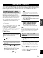
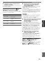
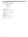
CAUTION: READ THIS BEFORE OPERATING YOUR UNIT.
En
1 To assure the finest performance, please read this manual
carefully. Keep it in a safe place for future reference.
2 Install this sound system in a well ventilated, cool, dry, clean
place – away from direct sunlight, heat sources, vibration,
dust, moisture, and/or cold. Allow ventilation space of at least
30 cm on the top, 20 cm on the left and right, and 20 cm on
the back of this unit.
3 Locate this unit away from other electrical appliances, motors,
or transformers to avoid humming sounds.
4 Do not expose this unit to sudden temperature changes from
cold to hot, and do not locate this unit in a environment with
high humidity (i.e. a room with a humidifier) to prevent
condensation inside this unit, which may cause an electrical
shock, fire, damage to this unit, and/or personal injury.
5 Avoid installing this unit where foreign object may fall onto
this unit and/or this unit may be exposed to liquid dripping or
splashing. On the top of this unit, do not place:
– other components, as they may cause damage and/or
discoloration on the surface of this unit.
– burning objects (i.e. candles), as they may cause fire,
damage to this unit, and/or personal injury.
– containers with liquid in them, as they may fall and liquid
may cause electrical shock to the user and/or damage to
this unit.
6 Do not cover this unit with a newspaper, tablecloth, curtain,
etc. in order not to obstruct heat radiation. If the temperature
inside this unit rises, it may cause fire, damage to this unit,
and/or personal injury.
7 Do not plug in this unit to a wall outlet until all connections
are complete.
8 Do not operate this unit upside-down. It may overheat,
possibly causing damage.
9 Do not use force on switches, knobs and/or cords.
10 When disconnecting the power cable from the wall outlet,
grasp the plug; do not pull the cord.
11 Do not clean this unit with chemical solvents; this might
damage the finish. Use a clean, dry cloth.
12 Only voltage specified on this unit must be used. Using this
unit with a higher voltage than specified is dangerous and may
cause fire, damage to this unit, and/or personal injury. Yamaha
will not be held responsible for any damage resulting from use
of this unit with a voltage other than specified.
13 To prevent damage by lightning, keep the power cord and
outdoor antennas disconnected from a wall outlet or the unit
during a lightning storm.
14 Do not attempt to modify or fix this unit. Contact qualified
Yamaha service personnel when any service is needed. The
cabinet should never be opened for any reasons.
15 When not planning to use this unit for long periods of time
(i.e. vacation), disconnect the AC power plug from the wall
outlet.
16 Install this unit near the AC outlet and where the AC power
plug can be reached easily.
17 Be sure to read the “Troubleshooting” section on common
operating errors before concluding that this unit is faulty.
18 Before moving this unit, press
A
STANDBY/ON to set this
unit in the standby mode, and disconnect the AC power plug
from the wall outlet.
19 VOLTAGE SELECTOR (Asia and General models only)
The VOLTAGE SELECTOR on the rear panel of this unit
must be set for your local main voltage BEFORE plugging
into the AC wall outlet. Voltages are:
Asia model ............................ 220/230–240 V AC, 50/60 Hz
General model ........ 110/120/220/230–240 V AC, 50/60 Hz
20 Excessive sound pressure from earphones and headphones can
cause hearing loss.
21 The batteries shall not be exposed to excessive heat such as
sunshine, fire or the like.
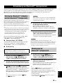
■ For U.K. customers
If the socket outlets in the home are not suitable for the
plug supplied with this appliance, it should be cut off and
an appropriate 3 pin plug fitted. For details, refer to the
instructions described below.
The plug severed from the mains lead must be destroyed, as a
plug with bared flexible cord is hazardous if engaged in a live
socket outlet.
■ Special Instructions for U.K. Model
Caution: Read this before operating your unit.
WARNING
TO REDUCE THE RISK OF FIRE OR ELECTRIC
SHOCK, DO NOT EXPOSE THIS UNIT TO RAIN
OR MOISTURE.
This unit is not disconnected from the AC power
source as long as it is connected to the wall outlet, even
if this unit itself is turned off by
A
STANDBY/ON.
This state is called the standby mode. In this state, this
unit is designed to consume a very small quantity of
power.
Note
IMPORTANT
THE WIRES IN MAINS LEAD ARE COLOURED IN
ACCORDANCE WITH THE FOLLOWING CODE:
Blue: NEUTRAL
Brown: LIVE
As the colours of the wires in the mains lead of this apparatus
may not correspond with the coloured markings identifying
the terminals in your plug, proceed as follows:
The wire which is coloured BLUE must be connected to the
terminal which is marked with the letter N or coloured
BLACK. The wire which is coloured BROWN must be
connected to the terminal which is marked with the letter L or
coloured RED.
Making sure that neither core is connected to the earth
terminal of the three pin plug.
This symbol mark is according to the
EU directive 2002/96/EC.
This symbol mark means that electrical
and electronic equipment, at their end-
of-life, should be disposed of separately
from your household waste.
Please act according to your local rules
and do not dispose of your old products
with your normal household waste.

1 En
English
PREPARATIONINTRODUCTION
BASIC
OPERATION
ADVANCED
OPERATION
ADDITIONAL
INFORMATION
APPENDIX
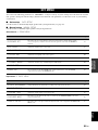
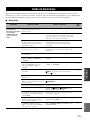
Features ................................................................... 2
Getting started ........................................................ 3
Quick start guide .................................................... 4
Preparation: Check the items ..................................... 4
Step 1: Set up your speakers...................................... 5
Step 2: Connect your DVD player and other
components............................................................ 6
Step 3: Press SCENE 1 button................................... 7
What do you want to do with this unit?..................... 8
Connections ............................................................. 9
Rear panel .................................................................. 9
Placing speakers....................................................... 10
Connecting speakers ................................................ 11
Information on jacks and cable plugs ...................... 13
Information on HDMI™.......................................... 14
Audio and video signal flow.................................... 14
Connecting video components................................. 15
Connecting other components ................................. 16
Connecting audio components................................. 18
Connecting a Yamaha iPod™ universal dock or
Bluetooth™ adapter............................................. 19
Using the VIDEO AUX jacks on the front panel .... 19
Connecting the FM and AM antennas ..................... 20
Connecting the power cable..................................... 20
Turning on and off the power .................................. 21
Front panel display .................................................. 22
Optimizing the speaker setting
for your listening room .................................... 24
Using AUTO SETUP .............................................. 24
Selecting the SCENE templates........................... 28
Selecting the desired SCENE template.................... 28
Creating your original SCENE templates................ 31
Using remote control on the SCENE feature........... 32
Playback ................................................................ 33
Basic operations....................................................... 33
Selecting audio input jacks
(AUDIO SELECT).............................................. 34
Selecting the MULTI CH INPUT component......... 34
Displaying the current status of this unit
on a video monitor............................................... 35
Using your headphones............................................ 35
Muting the audio output........................................... 35
Playing video sources in the background
of an audio source................................................ 36
Displaying the input source information ................. 36
Using the sleep timer ............................................... 37
Sound field programs ........................................... 38
Sound field program descriptions............................ 38
Using audio features ............................................. 41
Enjoying high quality sound.................................... 41
Adjusting the tonal quality....................................... 41
Adjusting the speaker level...................................... 41
Selecting the night listening mode........................... 42
FM/AM tuning ...................................................... 43
Automatic tuning ..................................................... 43
Manual tuning.......................................................... 43
Automatic preset tuning........................................... 44
Manual preset tuning ............................................... 44
Selecting preset stations........................................... 45
Exchanging preset station ........................................ 45
Radio Data System tuning
(Europe and Russia models only) ....................46
Displaying the Radio Data System information ...... 46
Selecting the Radio Data System program type
(PTY SEEK mode).............................................. 47
Using the enhanced other networks (EON) data
service.................................................................. 48
Using a USB memory device or a USB portable
audio player .......................................................49
Playback operation .................................................. 49
Using iPod™ ..........................................................51
Controlling iPod™................................................... 51
Using Bluetooth™ components ............................53
Pairing the Bluetooth™ adapter and your
Bluetooth™ component....................................... 53
Playback of the Bluetooth™ component................. 53
Recording ...............................................................54
SET MENU ............................................................55
Using SET MENU................................................... 56
1 SOUND MENU.................................................... 57
2 INPUT MENU...................................................... 62
3 OPTION MENU................................................... 64
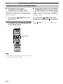
Remote control features........................................67
Controlling this unit, a TV, or other components.... 67
Setting remote control codes ................................... 69
Advanced setup......................................................70
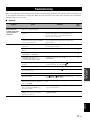
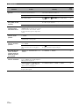
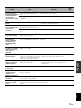
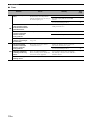
Troubleshooting.....................................................71
Glossary..................................................................81
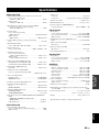
Specifications .........................................................83
Index .......................................................................84
(at the end of this manual)
Front panel................................................................i
Remote control ....................................................... ii
List of remote control codes ................................. iii
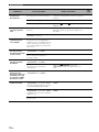
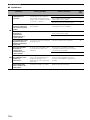
Contents
INTRODUCTION
PREPARATION
BASIC OPERATION
ADVANCED OPERATION
ADDITIONAL INFORMATION
APPENDIX
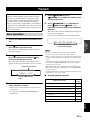
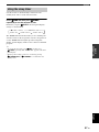
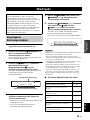
About this manual
• y indicates a tip for your operation.
• Some operations can be performed by using either the buttons on the
front panel or the ones on the remote control. In case the button
names differ between the front panel and the remote control, the
button name on the remote control is given in parentheses.
• This manual is printed prior to production. Design and specifications
are subject to change in part as a result of improvements, etc. In case
of differences between the manual and product, the product has
priority.
•“JSPEAKERS” or “3DVD” (example) indicates the name of the
parts on the front panel or the remote control. Refer to the attached
sheet or the pages at the end of this manual for the information about
each position of the parts.
• The symbol “☞ ” with page number(s) indicates the corresponding
reference page(s).

Features
2 En
Built-in 5-channel power amplifier
◆ Minimum RMS output power
[U.S.A. and Canada models]
(1 kHz, 0.9% THD, 8 Ω)
105 W/ch
[Other models]
(1 kHz, 0.9% THD, 6 Ω)
105 W/ch
SCENE select function
◆ Preset SCENE templates for various situations
◆ SCENE template customizing capability
Decoders and DSP circuits
◆ Proprietary Yamaha technology for the creation of multi-
channel surround sound
◆ Compressed Music Enhancer mode
◆ Dolby Digital decoder
◆ Dolby Pro Logic/Dolby Pro Logic II decoder
◆ DTS decoder
◆ Virtual CINEMA DSP
◆ SILENT CINEMA
™
Radio tuners
◆ FM/AM tuning capability
◆ Radio Data System capability (Europe model only)
HDMI (High-Definition Multimedia Interface)
◆ HDMI interface for standard, enhanced or high-definition
video (includes 1080p video signal transmission) as well as
multi-channel digital audio
DOCK terminal
◆ DOCK terminal to connect a Yamaha iPod universal dock
(such as YDS-10, sold separately) or Bluetooth adapter
(such as YBA-10, sold separately)
USB features
◆ USB port to connect a USB memory device or a USB portable
audio player
◆ MP3, WMA and WAV capability
Other features
◆ YPAO (Yamaha Parametric Room Acoustic Optimizer) for
automatic speaker setup
◆ 192-kHz/24-bit D/A converter
◆ DIRECT mode for high quality sound for all sources
◆ 6 additional input jacks for discrete multi-channel input
◆ OSD (on-screen display) menus that allow you to optimize
this unit to suit your individual audiovisual system
◆ Component video input/output capability
(3 COMPONENT VIDEO INs and 1 MONITOR OUT)
◆ Optical and coaxial digital audio signal jacks
◆ Sleep timer
◆ Cinema and music night listening modes
◆ iPod controlling capability
◆ Remote control with preset remote control codes
Manufactured under license from Dolby Laboratories.
“Dolby”, “Pro Logic”, and the double-D symbol are trademarks
of Dolby Laboratories.
“SILENT CINEMA” is a trademark of Yamaha Corporation.
iPod™
“iPod” is a trademark of Apple, Inc., registered in the U.S. and
other countries.
“DTS” and “DTS Digital Surround” are registered trademarks of
DTS, Inc.
Bluetooth™
Bluetooth is a registered trademark of the Bluetooth SIG and is
used by Yamaha in accordance with a license agreement.
“HDMI”, the “HDMI” logo and “High-Definition Multimedia
Interface” are trademarks or registered trademarks of HDMI
Licensing LLC.
Features

Getting started
3 En
English
INTRODUCTION
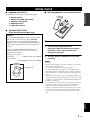
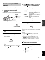
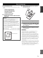
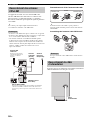
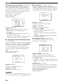
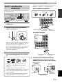
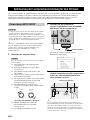
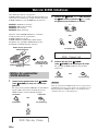
■ Supplied accessories
Check that you received all of the following parts.
❏ Remote control
❏ Batteries (2) (AAA, R03, UM-4)
❏ Optimizer microphone
❏ AM loop antenna
❏ Indoor FM antenna
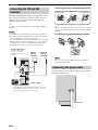
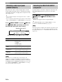
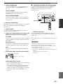
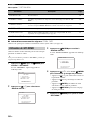
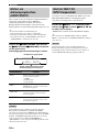
■ VOLTAGE SELECTOR
(Asia and General models only)
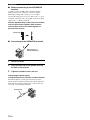
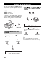
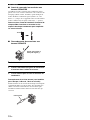
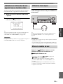
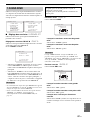
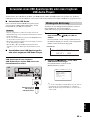
■ Installing batteries in the remote control
1 Take off the battery compartment cover.
2 Insert the two supplied batteries
(AAA, R03, UM-4) according to the polarity
markings (+ and –) on the inside of the
battery compartment.
3 Snap the battery compartment cover back
into place.
• Change all of the batteries if you notice that the operation range
of the remote control decreases.
• Do not use an old battery and a new one together.
• Do not use different types of batteries (such as alkaline and
manganese batteries) together. Read the packaging carefully as
these different types of batteries may have the same shape and
color.
• If the batteries have leaked, dispose of them immediately. Avoid
touching the leaked material or letting it come into contact with
clothing, etc. Clean the battery compartment thoroughly before
installing new batteries.
• Do not throw away batteries with general house waste; dispose
of them correctly in accordance with your local regulations.
• If the remote control is without batteries for more than 2
minutes, or if exhausted batteries remain in the remote control,
the contents of the memory may be cleared. When the memory
is cleared, insert new batteries and set up the remote control
code.
Getting started
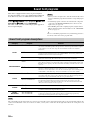
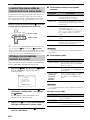
Caution
The VOLTAGE SELECTOR on the rear panel of this
unit must be set for your local voltage BEFORE
plugging the power cable into the AC wall outlet.
Improper setting of the VOLTAGE SELECTOR may
cause damage to this unit and create a potential fire
hazard.
Rotate the VOLTAGE SELECTOR clockwise or
counterclockwise to the correct position using a
straight slot screwdriver.
Voltages are as follows:
Asia model ................... 220/230–240 V AC, 50/60 Hz
General model
...................... 110/120/220/230–240 V AC, 50/60 Hz
230-
240V
VOLTAGE
SELECTOR
Voltage indication
Notes
1
3
2

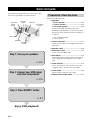
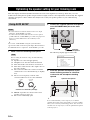
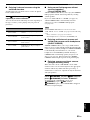
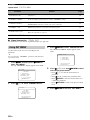
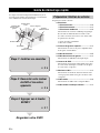
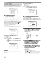
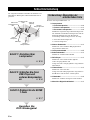
Quick start guide
4 En
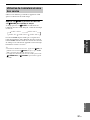
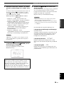
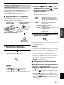
The following steps describe the easiest way to enjoy
DVD movie playback in your home theater.
Prepare the following items.
❏ Speakers
❏ Front speaker .....................................x 2
❏ Center speaker ...................................x 1
❏ Surround speaker ..............................x 2
Select magnetically shielded speakers. The
minimum required speakers are two front speakers.
The priority of the requirement of other speakers is
as follows:
1. Two surround speakers
2. Center speaker
❏ Active subwoofer ...................................x 1
Select an active subwoofer equipped with an RCA
input jack.
❏ Speaker cable .........................................x 5
❏ Subwoofer cable .....................................x 1
Select a monaural RCA cable.
❏ DVD player ..............................................x 1
Select DVD player equipped with coaxial digital
audio output jack and composite video output
jack.
❏ Video monitor..........................................x 1
Select a TV monitor, video monitor or projector
equipped with a composite video input jack.
❏ Video cable .............................................x 2
Select an RCA composite video cable.
❏ Digital coaxial audio cable ....................x 1
Quick start guide
Front right
speaker
Subwoofer
Surround left
speaker
Front left
speaker
Surround right
speaker
Center speaker
DVD player
Video monitor
Enjoy DVD playback!
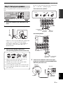
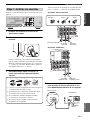
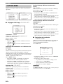
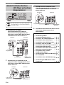
Step 1: Set up your speakers
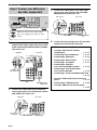
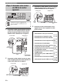
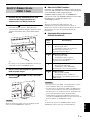
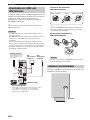
Step 2: Connect your DVD player
and other components
Step 3: Press SCENE 1 button
☞
P. 6
☞
P. 7
☞
P. 5
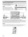
Preparation: Check the items

Quick start guide
5 En
English
INTRODUCTION
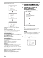
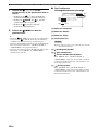
Place your speakers in the room and connect them to this
unit.
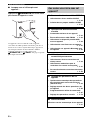
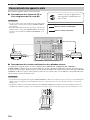
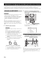
1 Place your speakers and subwoofer in the
room.
2 Connect speaker cables to each speaker.
Cables are colored or shaped differently, perhaps with
a stripe, groove or ridge. Connect the striped
(grooved, etc.) cable to the “+” (red) terminals of
your speaker. Connect the plain cable to the “–”
(black) terminals.
3 Connect each speaker cable to the
corresponding speaker terminal of this unit.
1 Make sure that this unit and the subwoofer are
unplugged from the AC wall outlets.
2 Twist the exposed wires of the speaker cables
together to prevent short circuits.
3 Do not let the bare speaker wires touch each other.
4 Do not let the bare speaker wires touch any metal
part of this unit.
Be sure to connect the left channel (L), right channel
(R), “+” (red) and “–” (black) properly.
Front and center speakers
Surround speakers
4 Connect the subwoofer cable to the input
jack of the subwoofer and the SUBWOOFER
OUTPUT jack of this unit.
Step 1: Set up your speakers
LR
SURROUND
LR
FRONT B
LR
FRONT ACENTER
MONITOR
OUT
L
R
DTV/CBL DVRDVD
MD/
CD-R
OUT
(REC)
IN
(PLAY)
OUT
IN
DTV/CBL DVRDVD
OUTIN
CD
L
R
SUB
WOOFER
SUB
WOOFER
SURROUND
CENTER
MULTI CH INPUTAUDIO
VIDEO
OUTPUT
FRONT
1
2
3
DTV/CBL
DTV/CBL CD
OUT
DTV/CBL
DVR
DVD
DVD
OPTICAL
COAXIAL
DVD
P
R
P
B
YP
R
P
B
Y
MONITOR OUT
AM
GND
FM
75
UNBAL.
COMPONENT VIDEO ANTENNA
SPEAKERS
HDMI DIGITAL INPUT
VIDEO
DOCK
IN1 IN2
LR
SURROUND
LR
FRONT B
LR
FRONT ACENTER
SUB
WOOFER
OUTPUT
SPEAKERS
12 3 4
To the front
right speaker
To the front
left speaker
Loosen Insert Tighten
To the center
speaker
To the surround
left speaker
To the surround
right speaker
SUBWOOFER
OUTPUT jack
Subwoofer cable
Input jack
AV receiver
Subwoofer

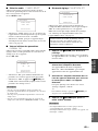
Quick start guide
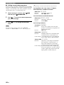
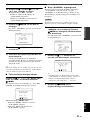
6 En
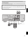
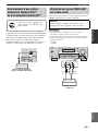
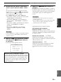
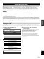
1 Connect the digital coaxial audio cable to the
digital coaxial audio output jack of your DVD
player and the DVD DIGITAL INPUT COAXIAL
jack of this unit.
2 Connect the video cable to the composite
video output jack of your DVD player and the
DVD VIDEO jack of this unit.
3 Connect the video cable to the video input
jack of your video monitor and the VIDEO
MONITOR OUT jack of this unit.
4 Connect the power plug of this unit and other
components into the AC wall outlet.
Step 2: Connect your DVD player
and other components
LR
SURROUND
LR
FRONT B
LR
FRONT ACENTER
MONITOR
OUT
L
R
DTV/CBL DVRDVD
MD/
CD-R
OUT
(REC)
IN
(PLAY)
OUT
IN
DTV/CBL DVRDVD
OUTIN
CD
L
R
SUB
WOOFER
SUB
WOOFER
SURROUND
CENTER
MULTI CH INPUTAUDIO
VIDEO
OUTPUT
FRONT
1
2
3
DTV/CBL
DTV/CBL CD
OUT
DTV/CBL
DVR
DVD
DVD
OPTICAL
COAXIAL
DVD
P
R
P
B
YP
R
P
B
Y
MONITOR OUT
AM
GND
FM
75
UNBAL.
COMPONENT VIDEO ANTENNA
SPEAKERS
HDMI DIGITAL INPUT
VIDEO
IN1 IN2
DOCK
MONITOR
OUT
DTV/CBL DVRDVD
OUTIN
VIDEO
1
2
3
DTV/CBL CDDVD
OPTICAL
COAXIAL
DIGITAL INPUT
VIDEO
Make sure that this unit and the DVD
player are unplugged from the AC wall
outlets.
Digital coaxial
audio output jack
Digital coaxial audio
cable
DVD DIGITAL INPUT
COAXIAL jack
DVD player
AV receiver
Composite video
output jack
Video cable
DVD VIDEO jack
DVD player
AV receiver
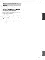
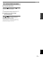
■ For further connections
• Using the other kind of speaker
combinations ☞ P. 11
• Connecting video components ☞ P. 15
• Connecting a DVD player ☞ P. 16
• Connecting a DVD recorder ☞ P. 17
• Connecting a set-top box ☞ P. 17
• Connecting a CD player
and a CD recorder/MD recorder ☞ P. 18
• Connecting a multi-format player
or an external decoder ☞ P. 18
• Connecting a Yamaha iPod/Bluetooth dock
☞ P. 19
• Using the VIDEO AUX jacks on the front
panel ☞ P. 19
• Connecting an FM/AM antenna ☞ P. 20
• Using the USB jack on the front panel
☞ P. 49
Video monitor
AV receiver
Video input
jack
VIDEO MONITOR OUT
jack
Video cable

Quick start guide
7 En
English
INTRODUCTION
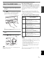
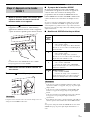
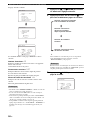
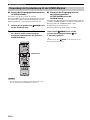
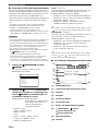
1 Turn on the video monitor and then set the
input source selector of the video monitor to
this unit.
2 Press
Q
SCENE 1.
This unit is turned on. “DVD Viewing” appears in the
front panel display, and this unit automatically
optimize own status for the DVD playback.
y
The indicator on the selected SCENE button lights up while
this unit is in the SCENE mode.
3 Start playback of the desired DVD on your
player.
4 Rotate
I
VOLUME to adjust the volume.
When you change the input source or sound field program, the
SCENE mode is deactivated.
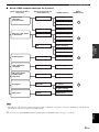
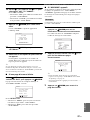
■ About SCENE function
Just by pressing one SCENE button, you can turn on this
unit and recall your favorite input source and sound field
program according to the SCENE template that has been
assigned to the SCENE button. The SCENE templates are
built combinations of input sources and sound field
programs.
y
If you connect a Yamaha product that has capability of the
SCENE control signals, this unit can automatically activate the
component and start playback. Refer to the instruction manual of
the DVD player for further information.
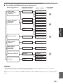
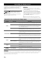
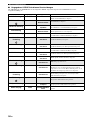
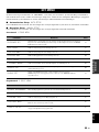
■ The default assigned SCENE templates
*1
You must connect a cable TV or a satellite tuner to this unit in
advance. See page 17 for details.
*2
You need to connect the supplied FM and AM antennas to this
unit in advance. See page 20 for details.
*3
You must tune into the desired radio station in advance. See
pages 43 to 45 for tuning information.
*4
To achieve the best possible reception, orient the connected
AM loop antenna, or adjust the position of the end of the
indoor FM antenna.
y
You can change the assigned SCENE template for the SCENE
buttons. See page 28 for details.
Step 3: Press SCENE 1 button
Note
Default
SCENE
button
The name of the SCENE template
and its description
SCENE
1
DVD Movie Viewing
– input source: DVD
– sound field program: Movie Dramatic
For when you want to enjoy a movie from the
connected DVD player.
SCENE
2
Music Disc Listening
– input source: DVD
– sound field program: 2ch Stereo
For when you want to listen to a music disc from
the connected DVD player.
SCENE
3
TV Viewing
*1
– input source: DTV/CBL
– sound field program: STRAIGHT
For when you want to watch a TV program.
SCENE
4
Radio Listening
*2, *3, *4
– input source: TUNER
– sound field program: 5ch Enhancer
For when you want to listen to a music program
from the FM radio station.
Notes

Quick start guide
8 En
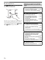
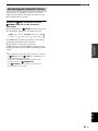
■ After using this unit...
Press
A
STANDBY/ON on the front panel to set
this unit to the standby mode.
This unit is set to the standby mode. In the standby mode,
this unit consumes a small amount of power in order to
receive infrared signals from the remote control. To turn
on this unit from the standby mode, press
A
STANDBY/
ON (or GPOWER). See page 21 for details.
What do you want to do with this
unit?
■ Customizing the SCENE templates
• Using various SCENE templates ☞ P. 28
• Creating your original SCENE templates
☞ P. 31
■ Using various input sources
• Basic controls of this unit ☞ P. 33
• Enjoying FM/AM radio programs ☞ P. 43
• Using your USB portable device
with this unit ☞ P. 49
• Using your iPod with this unit ☞ P. 51
• Using your Bluetooth components
with this unit ☞ P. 53
■ Using various sound features
• Using various sound field programs
☞ P. 38
• Using the direct mode for the high
quality sound ☞ P. 41
• Customizing the sound field programs
☞ P. 40
■ Adjusting the parameters of this unit
• Automatically optimizing the speaker
parameters for your listening room
(AUTO SETUP) ☞ P. 24
• Manually adjusting various parameters of
this unit ☞ P. 55
• Setting the remote control ☞ P. 67
• Adjusting the advanced parameters☞ P. 70
■ Additional features
Automatically turning off this unit ☞ P. 37

Connections
9 En
English
PREPARATION
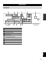
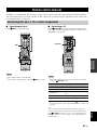
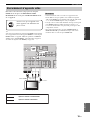
Connections
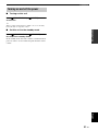
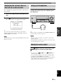
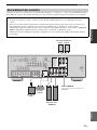
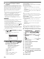
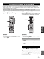
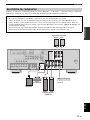
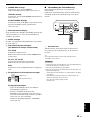
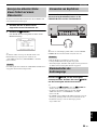
Rear panel
LR
SURROUND
LR
FRONT B
LR
FRONT ACENTER
MONITOR
OUT
L
R
DTV/CBL DVRDVD
MD/
CD-R
OUT
(REC)
IN
(PLAY)
OUT
IN
DTV/CBL DVRDVD
OUTIN
CD
L
R
SUB
WOOFER
SUB
WOOFER
SURROUND
CENTER
MULTI CH INPUTAUDIO OUTPUT
FRONT
1
2
3
DTV/CBL
DTV/CBL CD
OUT
DTV/CBL
DVR
DVD
DVD
OPTICAL
COAXIAL
DVD
P
R
P
B
YP
R
P
B
Y
MONITOR OUT
AM
GND
FM
75
UNBAL.
COMPONENT VIDEO ANTENNA
SPEAKERS
HDMI DIGITAL INPUT
VIDEO
DOCK
IN1 IN2
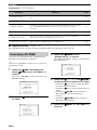
1
2 3 4 5
6
A8 097
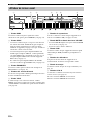
Name Page
1 HDMI jacks 14
2 DIGITAL INPUT jacks 13
3 COMPONENT VIDEO jacks 13
4 DOCK terminal 19
5 Speaker terminals 11
6 VOLTAGE SELECTOR
(Asia and General models only)
3
7 AUDIO jacks 13
8 VIDEO jacks 13
9 MULTI CH INPUT jacks 18
0 SUBWOOFER OUTPUT jack 11
A ANTENNA terminals 20

10 En
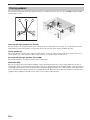
Connections
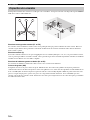
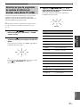
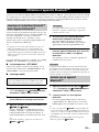
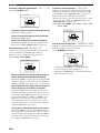
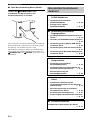
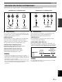
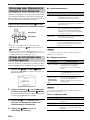
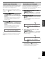
The speaker layout below shows the speaker setting we recommend. You can use it to enjoy CINEMA DSP and multi-
channel audio sources.
Front left and right speakers (FL and FR)
The front speakers are used for the main source sound plus effect sounds. Place these speakers at an equal distance from the
ideal listening position. The distance of each speaker from each side of the video monitor should be the same.
Center speaker (C)
The center speaker is for the center channel sounds (dialog, vocals, etc.). If for some reason it is not practical to use a
center speaker, you can do without it. Best results, however, are obtained with the full system.
Surround left and right speakers (SL and SR)
The surround speakers are used for effect and surround sounds.
Subwoofer (SW)
The use of a subwoofer with a built-in amplifier, such as the Yamaha Active Servo Processing Subwoofer System, is
effective not only for reinforcing bass frequencies from any or all channels, but also for high fidelity sound reproduction
of the LFE (low-frequency effect) channel included in Dolby Digital and DTS sources. The position of the subwoofer is
not so critical, because low bass sounds are not highly directional. But it is better to place the subwoofer near the front
speakers. Turn it slightly toward the center of the room to reduce wall reflections.
Placing speakers
FR
FL
C
SL
SR
SW
60˚
30˚
FL
FR
C
SL
SR
SR
80˚
SL

11 En
Connections
English
PREPARATION
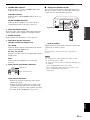
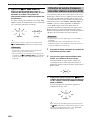
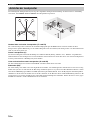
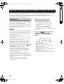
Be sure to connect the left channel (L), right channel (R), “+” (red) and “–” (black) properly. If the connections are faulty,
this unit cannot reproduce the input sources accurately.
Connecting speakers
Caution
• Before connecting the speakers, make sure that the AC power plug is disconnected from the AC wall outlet.
• Do not let the bare speaker wires touch each other or let them touch any metal part of this unit. This could damage
this unit and/or the speakers. If the speaker wires are short-circuited, “CHECK SP WIRES” appears in the front
panel display when you turn on this unit.
• Use the magnetically shielded speakers. If this type of speaker still creates interference with the monitor, place the
speakers away from the monitor.
LR
SURROUND
LR
FRONT B
LR
FRONT ACENTER
MONITOR
OUT
L
R
DTV/CBL DVRDVD
MD/
CD-R
OUT
(REC)
IN
(PLAY)
OUT
IN
DTV/CBL DVRDVD
OUTIN
CD
L
R
SUB
WOOFER
SUB
WOOFER
SURROUND
CENTER
MULTI CH INPUTAUDIO
VIDEO
OUTPUT
FRONT
1
2
3
DTV/CBL
DTV/CBL CD
OUT
DTV/CBL
DVR
DVD
DVD
OPTICAL
COAXIAL
DVD
P
R
P
B
YP
R
P
B
Y
MONITOR OUT
AM
GND
FM
75
UNBAL.
COMPONENT VIDEO ANTENNA
SPEAKERS
HDMI DIGITAL INPUT
VIDEO
DOCK
IN1 IN2
Front speakers
(FRONT A)
Surround speakers
Subwoofer
Center
speaker
Left
Left
Right
Right
FRONT B terminals
Connect the alternative front speaker system
(FRONT B).

12 En
Connections
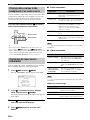
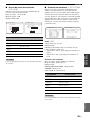
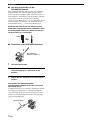
■ Before connecting to the SPEAKERS
terminal
A speaker cord is actually a pair of insulated cables
running side by side. Cables are colored or shaped
differently, perhaps with a stripe, groove or ridges.
Connect the striped (grooved, etc.) cable to the “+” (red)
terminals of this unit and your speaker. Connect the plain
cable to the “–” (black) terminals.
Remove approximately 10 mm (3/8”) of insulation
from the end of each speaker cable and then
twist the bare wires of the cable together to
prevent short circuits.
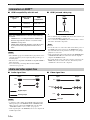
■ Connecting to the SPEAKER terminals
1 Loosen the knob.
2 Insert the bare end of the speaker wire into
the hole on the terminal.
3 Tighten the knob to secure the wire.
Connecting the banana plug
(except Europe, Russia, Korea, and Asia models)
The banana plug is a single-pole electrical connector
widely used to terminate speaker cables. First, tighten the
knob and then insert the banana plug connector into the
end of the corresponding terminal.
10 mm (3/8”)
1
2
3
Red: positive (+)
Black: negative (–)
Banana plug

13 En
Connections
English
PREPARATION
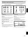
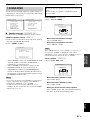
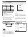
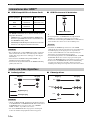
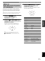
Connect one of the type of the audio jack(s) and/or video jack(s) that your input components are equipped with.
■ Audio jacks
This unit has three types of audio jacks. Connection
depends on the availability of audio jacks on your other
components.
AUDIO jacks
For conventional analog audio signals transmitted via left
and right analog audio cables. Connect red plugs to the
right jacks and white plugs to the left jacks.
DIGITAL AUDIO COAXIAL jack
For digital audio signals transmitted via a coaxial digital
audio cable.
DIGITAL AUDIO OPTICAL jacks
For digital audio signals transmitted via optical digital
audio cables.
• You can use the digital jacks to input PCM, Dolby Digital and
DTS bitstreams. Optical input jacks are compatible with digital
signals with up to 96 kHz of sampling frequency.
• This unit handles digital and analog signals independently. Thus
audio signals input at the digital jacks are not output at the
analog AUDIO OUT (REC) jacks.
■ Video jacks
This unit has two types of video jacks. Connection
depends on the availability of input jacks on your video
monitor.
VIDEO jacks
For conventional composite video signals transmitted via
composite video cables.
COMPONENT VIDEO jacks
For component signals, separated into the luminance (Y)
and chrominance (P
B, PR) video signals transmitted on
separate wires of component video cables.
The OSD signal is not output at the DVR OUT (REC) jacks.
Information on jacks and cable plugs
VIDEO
COMPONENT VIDEO
P
R
P
B
Y
PB
PR
Y
V
COAXIAL
DIGITAL AUDIO
AUDIO
OPTICAL
DIGITAL AUDIO
R
L
C
O
R
L
Left and right
analog audio
cable plugs
Optical
digital
audio cable
plug
Coaxial
digital audio
cable plug
Composite
video cable
plug
Component
video cable
plugs
Audio jacks and cable plugs Video jacks and cable plugs
(Red)(White) (Orange)
(Yellow)
(Red) (Blue) (Green)
Notes
Note
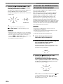
PR PB YPR PB Y
Video signal flow for MONITOR OUT
Output
(MONITOR OUT)
Input
COMPONENT
VIDEO
VIDEO

14 En
Connections
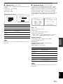
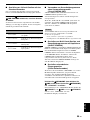
■ HDMI compatibility with this unit
• When CPPM copy-protected DVD audio is played back, video
and audio signals may not be output depending on the type of
the DVD player.
• This unit is not compatible with HDCP-incompatible HDMI or
DVI components.
• You can check the potential problem about the HDMI
connection (see page 36).
■ HDMI jack and cable plug
y
• We recommend using an HDMI cable shorter than 5 meters (16
feet) with the HDMI logo printed on it.
• Use a conversion cable (HDMI jack
↔ DVI-D jack) to connect
this unit to other DVI components.
• Do not disconnect or connect the cable or turn off the power of
the HDMI components connected to the HDMI OUT jack of
this unit while data is being transferred. Doing so may disrupt
playback or cause noise.
• Audio signals input at input jacks other than the HDMI IN DVD
or HDMI IN DTV/CBL jack of this unit cannot be digitally
output at the HDMI OUT jack.
• If you turn off the power of the video monitor connected to the
HDMI OUT jack via a DVI connection, this unit may fail to
establish the connection to the component.
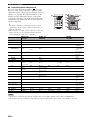
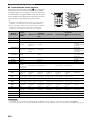
■ Audio signal flow
• 2-channel as well as multi-channel PCM, Dolby Digital and
DTS signals input at the HDMI IN DVD or HDMI IN DTV/
CBL jack can be output at the HDMI OUT jack only when
“SUPPORT AUDIO” is set to “Other” (see page 61).
• Audio signals input at the HDMI IN jacks are not output at the
AUDIO output jacks.
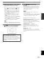
■ Video signal flow
Information on HDMI™
Audio signal
types
Audio signal
formats
Compatible
HDMI
components
2ch Linear PCM 2ch, 32-192 kHz,
16/20/24 bit
CD, DVD-Video,
DVD-Audio, etc.
Multi-ch Linear
PCM
8ch, 32-192 kHz,
16/20/24 bit
DVD-Audio, etc.
Bitstream Dolby Digital, DTS DVD-Video, etc.
This unit’s HDMI interface is based on the following
standards:
• HDMI Version 1.2a (High-Definition Multimedia
Interface Specification Version 1.2a) licensed by
HDMI Licensing, LLC.
• HDCP (High-bandwidth Digital Content Protection
System) licensed by Digital Content Protection,
LLC.
Notes
Notes
HDMI
HDMI cable plug
Audio and video signal flow
Notes
HDMI
AUDIO
OutputInput
Analog output
Digital output
VIDEO
COMPONENT
VIDEO
HDMI
Through
OutputInput

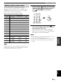
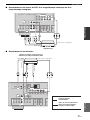
15 En
Connections
English
PREPARATION
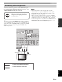
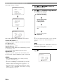
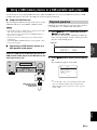
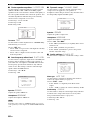
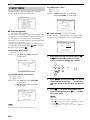
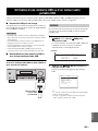
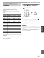
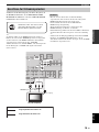
Connect your TV (or projector) to the HDMI OUT jack,
the COMPONENT VIDEO MONITOR OUT jacks, or the
VIDEO MONITOR OUT jack of this unit.
y
You can choose to play back HDMI audio signals on this unit or
on another HDMI component connected to the HDMI OUT jack
of this unit. Use the “SUPPORT AUDIO” parameter in “SOUND
MENU” to select the component to play back HDMI audio
signals (see page 61).
• Some video monitors connected to this unit via a DVI
connection fail to recognize the HDMI audio/video signals
being input if they are in the standby mode. In this case, the
HDMI indicator flashes irregularly.
• When you connect your TV monitor or projector via HDMI
connection, the OSD does not appear. In such cases, connect the
TV monitor or projector via component, or video connection.
• Connect the input source components to the HDMI IN DVD or
HDMI IN DTV/CBL jack to display the video images on the
video monitor connected to the HDMI OUT jack.
Connecting video components
Make sure that this unit and other
components are unplugged from the
AC wall outlets.
Notes
MONITOR
OUT
DTV/CBL DVRDVD
D
/
-R
OUT
(REC)
OUTIN
DTV/CBL DVRDVD
OUTIN
CD
L
R
SUB
WOOFER
W
O
SURROUND
CENTER
MULTI CH INPUTAUDIO OUTPUT
FRONT
1
2
3
DTV/CBL
DTV/CBL CD
OUT
DTV/CBL
DVR
V
D
DVD
OPTICAL
COAXIAL
DVD
P
R
P
B
YP
R
P
B
Y
MONITOR OUT
COMPONENT VIDEO
HDMI DIGITAL INPUT
VIDEO
IN1 IN2
MONITOR
OUT
OUT
P
R
P
B
Y
MONITOR OUT
COMPONENT VIDEO
HDMI
VIDEO
PR PB
V
Y
TV (or projector)
Video in
Component
video in
HDMI in
indicates recommended connections
indicates alternative connections

16 En
Connections
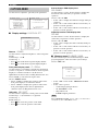
• Be sure to make the same type of video connections as those
made for your TV (see page 15).
• To make a digital connection to a component other than the
default component assigned to DIGITAL INPUT jack, select
the corresponding setting for “OPTICAL IN” or “COAXIAL
IN” in “INPUT ASSIGNMENT” (see page 62).
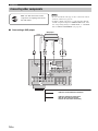
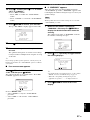
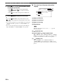
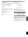
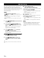
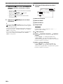
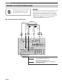
■ Connecting a DVD player
Connecting other components
Make sure that this unit and other
components are unplugged from the
AC wall outlets.
Notes
MONITOR
OUT
L
R
DTV/CBL DVRDVD
MD/
CD-R
OUT
(REC)
IN
(PLAY)
OUT
IN
DTV/CBL DVRDVD
OUTIN
CD
L
R
SUB
WOOFER
W
O
SURROUND
CENTER
MULTI CH INPUTAUDIO
VIDEO
OUTPUT
FRONT
1
2
3
DTV/CBL
DTV/CBL CD
OUT
DTV/CBL
DVR
DVD
DVD
OPTICAL
COAXIAL
DVD
P
R
P
B
YP
R
P
B
Y
MONITOR OUT
COMPONENT VIDEO
HDMI DIGITAL INPUT
VIDEO
IN1 IN2
L
R
DVD
DVD
AUDIO
1
DVD
DVD
COAXIAL
DVD
P
R
P
B
Y
COMPONENT VIDEO
HDMI DIGITAL INPUT
VIDEO
IN1
LR
C
V
PR PB Y
DVD player
HDMI out
Component
video out
Video out
Audio out
indicates recommended connections
indicates alternative connections
(One for the video connection,
and one for the audio connection)
Coaxial out

17 En
Connections
English
PREPARATION
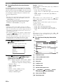
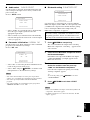
■ Connecting a DVD recorder, PVR or VCR
■ Connecting a set-top box
MONITOR
OUT
L
R
DTV/CBL DVRDVD
MD/
CD-R
OUT
(REC)
IN
(PLAY)
OUT
IN
DTV/CBL DVRDVD
OUTIN
CD
L
R
SUB
WOOFER
W
O
SURROUND
CENTER
MULTI CH INPUTAUDIO
VIDEO
OUTPUT
FRONT
1
2
3
DTV/CBL
DTV/CBL CD
OUT
DTV/CBL
DVR
DVD
DVD
DVD
P
R
P
B
YP
R
P
B
Y
MONITOR OUT
COMPONENT VIDEO
HDMI DIGITAL INPUT
VIDEO
IN1 IN2
L
R
DVR
OUT
IN
DVR
OUTIN
AUDIO
VIDEO
DVR
P
R
P
B
Y
COMPONENT VIDEO
VIDEO
V
R
L
R
L
V
PR PB Y
Video out
Audio out
Audio in
Video in
Component video out
DVD recorder,
PVR or VCR
MONITOR
OUT
L
R
DTV/CBL DVRDVD
MD/
CD-R
OUT
(REC)
IN
(PLAY)
OUT
IN
DTV/CBL DVRDVD
OUTIN
CD
L
R
SUB
WOOFER
W
O
SURROUND
CENTER
MULTI CH INPUTAUDIO
VIDEO
OUTPUT
FRONT
1
2
3
DTV/CBL
DTV/CBL CD
OUT
DTV/CBL
DVR
DVD
DVD
OPTICAL
COAXIAL
DVD
P
R
P
B
YP
R
P
B
Y
MONITOR OUT
COMPONENT VIDEO
HDMI DIGITAL INPUT
VIDEO
IN1 IN2
L
R
DTV/CBL
DTV/CBL
AUDIO
VIDEO
DTV/CBL
DTV/CBL
P
R
P
B
Y
COMPONENT VIDEO
HDMI DIGITAL INPUT
VIDEO
IN2
2
DTV/CBL
OPTICAL
O
V
L R
PR PB Y
Satellite receiver, cable TV
receiver or HDTV decoder
HDMI out Component video out
Audio out
Video out
Optical out
indicates recommended
connections
indicates alternative
connections (One for the video
connection, and one for the
audio connection)

18 En
Connections
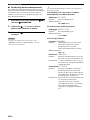
Connect the audio components as follows.
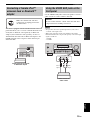
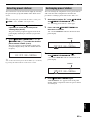
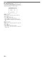
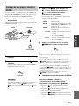
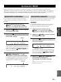
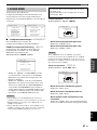
■ Connecting a CD player and a CD
recorder/MD recorder
• When you connect your CD player via analog and digital
connection, priority is given to the signal input at the DIGITAL
INPUT jack.
• To make a digital connection to a component other than the
default component assigned to each DIGITAL INPUT jack,
select the corresponding setting in “INPUT ASSIGNMENT”
(see page 62).
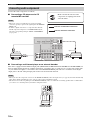
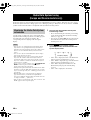
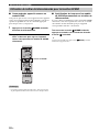
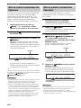
■ Connecting a multi-format player or an external decoder
This unit is equipped with 6 additional input jacks (FRONT L/R, SURROUND L/R, CENTER and SUBWOOFER) for
discrete multi-channel input from a multi-format player, external decoder or sound processor. Connect the output jacks
on your multi-format player or external decoder to the MULTI CH INPUT jacks. Be sure to match the left and right
output jacks to the left and right input jacks for the front and surround channels.
• When you select the component connected to the MULTI CH INPUT jacks as the input source (see page 34), this unit automatically
turns off the digital sound field processor, and you cannot select sound field programs.
• This unit does not redirect signals input at the MULTI CH INPUT jacks to accommodate for missing speakers. We recommend that
you connect a 5.1-channel speaker system before using this feature.
Connecting audio components
Make sure that this unit and other
components are unplugged from the
AC wall outlets.
Notes
indicates recommended connections
indicates alternative connections
Notes
MONITOR
OUT
L
R
DTV/CBL DVRDVD
MD/
CD-R
OUT
(REC)
IN
(PLAY)
OUT
IN
DTV/CBL DVRDVD
OUTIN
CD
L
R
W
SURROUND
MULTI CH INP
U
AUDIO
VIDEO
FRONT
1
2
3
DTV/CBL
DTV/CBL CD
OUTDVD
DVD
OPTICAL
COAXIAL
DVD
P
R
P
B
YP
R
MONITOR OUT
COMPONENT VIDEO
HDMI DIGITAL INPUT
VIDEO
IN1 IN2
L
R
MD/
CD-R
OUT
(REC)
IN
(PLAY)
CD
AUDIO
3
CD
OPTICAL
DIGITAL INPUT
L
R
O
R
L
L
R
CD player
CD recorder or
MD recorder
Audio out
Optical out
Audio in
Audio out
FRONT
CENTER
SURROUND
SUB
WOOFER
L
R
MULTI CH INPUT
L R LR
Subwoofer out
Multi-format player/
External decoder
Center out
Surround out
Front out
Pagina se încarcă ...
Pagina se încarcă ...
Pagina se încarcă ...
Pagina se încarcă ...
Pagina se încarcă ...
Pagina se încarcă ...
Pagina se încarcă ...
Pagina se încarcă ...
Pagina se încarcă ...
Pagina se încarcă ...
Pagina se încarcă ...
Pagina se încarcă ...
Pagina se încarcă ...
Pagina se încarcă ...
Pagina se încarcă ...
Pagina se încarcă ...
Pagina se încarcă ...
Pagina se încarcă ...
Pagina se încarcă ...
Pagina se încarcă ...
Pagina se încarcă ...
Pagina se încarcă ...
Pagina se încarcă ...
Pagina se încarcă ...
Pagina se încarcă ...
Pagina se încarcă ...
Pagina se încarcă ...
Pagina se încarcă ...
Pagina se încarcă ...
Pagina se încarcă ...
Pagina se încarcă ...
Pagina se încarcă ...
Pagina se încarcă ...
Pagina se încarcă ...
Pagina se încarcă ...
Pagina se încarcă ...
Pagina se încarcă ...
Pagina se încarcă ...
Pagina se încarcă ...
Pagina se încarcă ...
Pagina se încarcă ...
Pagina se încarcă ...
Pagina se încarcă ...
Pagina se încarcă ...
Pagina se încarcă ...
Pagina se încarcă ...
Pagina se încarcă ...
Pagina se încarcă ...
Pagina se încarcă ...
Pagina se încarcă ...
Pagina se încarcă ...
Pagina se încarcă ...
Pagina se încarcă ...
Pagina se încarcă ...
Pagina se încarcă ...
Pagina se încarcă ...
Pagina se încarcă ...
Pagina se încarcă ...
Pagina se încarcă ...
Pagina se încarcă ...
Pagina se încarcă ...
Pagina se încarcă ...
Pagina se încarcă ...
Pagina se încarcă ...
Pagina se încarcă ...
Pagina se încarcă ...
Pagina se încarcă ...
Pagina se încarcă ...
Pagina se încarcă ...
Pagina se încarcă ...
Pagina se încarcă ...
Pagina se încarcă ...
Pagina se încarcă ...
Pagina se încarcă ...
Pagina se încarcă ...
Pagina se încarcă ...
Pagina se încarcă ...
Pagina se încarcă ...
Pagina se încarcă ...
Pagina se încarcă ...
Pagina se încarcă ...
Pagina se încarcă ...
Pagina se încarcă ...
Pagina se încarcă ...
Pagina se încarcă ...
Pagina se încarcă ...
Pagina se încarcă ...
Pagina se încarcă ...
Pagina se încarcă ...
Pagina se încarcă ...
Pagina se încarcă ...
Pagina se încarcă ...
Pagina se încarcă ...
Pagina se încarcă ...
Pagina se încarcă ...
Pagina se încarcă ...
Pagina se încarcă ...
Pagina se încarcă ...
Pagina se încarcă ...
Pagina se încarcă ...
Pagina se încarcă ...
Pagina se încarcă ...
Pagina se încarcă ...
Pagina se încarcă ...
Pagina se încarcă ...
Pagina se încarcă ...
Pagina se încarcă ...
Pagina se încarcă ...
Pagina se încarcă ...
Pagina se încarcă ...
Pagina se încarcă ...
Pagina se încarcă ...
Pagina se încarcă ...
Pagina se încarcă ...
Pagina se încarcă ...
Pagina se încarcă ...
Pagina se încarcă ...
Pagina se încarcă ...
Pagina se încarcă ...
Pagina se încarcă ...
Pagina se încarcă ...
Pagina se încarcă ...
Pagina se încarcă ...
Pagina se încarcă ...
Pagina se încarcă ...
Pagina se încarcă ...
Pagina se încarcă ...
Pagina se încarcă ...
Pagina se încarcă ...
Pagina se încarcă ...
Pagina se încarcă ...
Pagina se încarcă ...
Pagina se încarcă ...
Pagina se încarcă ...
Pagina se încarcă ...
Pagina se încarcă ...
Pagina se încarcă ...
Pagina se încarcă ...
Pagina se încarcă ...
Pagina se încarcă ...
Pagina se încarcă ...
Pagina se încarcă ...
Pagina se încarcă ...
Pagina se încarcă ...
Pagina se încarcă ...
Pagina se încarcă ...
Pagina se încarcă ...
Pagina se încarcă ...
Pagina se încarcă ...
Pagina se încarcă ...
Pagina se încarcă ...
Pagina se încarcă ...
Pagina se încarcă ...
Pagina se încarcă ...
Pagina se încarcă ...
Pagina se încarcă ...
Pagina se încarcă ...
Pagina se încarcă ...
Pagina se încarcă ...
Pagina se încarcă ...
Pagina se încarcă ...
Pagina se încarcă ...
Pagina se încarcă ...
Pagina se încarcă ...
Pagina se încarcă ...
Pagina se încarcă ...
Pagina se încarcă ...
Pagina se încarcă ...
Pagina se încarcă ...
Pagina se încarcă ...
Pagina se încarcă ...
Pagina se încarcă ...
Pagina se încarcă ...
Pagina se încarcă ...
Pagina se încarcă ...
Pagina se încarcă ...
Pagina se încarcă ...
Pagina se încarcă ...
Pagina se încarcă ...
Pagina se încarcă ...
Pagina se încarcă ...
Pagina se încarcă ...
Pagina se încarcă ...
Pagina se încarcă ...
Pagina se încarcă ...
Pagina se încarcă ...
Pagina se încarcă ...
Pagina se încarcă ...
Pagina se încarcă ...
Pagina se încarcă ...
Pagina se încarcă ...
Pagina se încarcă ...
Pagina se încarcă ...
Pagina se încarcă ...
Pagina se încarcă ...
Pagina se încarcă ...
Pagina se încarcă ...
Pagina se încarcă ...
Pagina se încarcă ...
Pagina se încarcă ...
Pagina se încarcă ...
Pagina se încarcă ...
Pagina se încarcă ...
Pagina se încarcă ...
Pagina se încarcă ...
Pagina se încarcă ...
Pagina se încarcă ...
Pagina se încarcă ...
Pagina se încarcă ...
Pagina se încarcă ...
Pagina se încarcă ...
Pagina se încarcă ...
Pagina se încarcă ...
Pagina se încarcă ...
Pagina se încarcă ...
Pagina se încarcă ...
Pagina se încarcă ...
Pagina se încarcă ...
Pagina se încarcă ...
Pagina se încarcă ...
Pagina se încarcă ...
Pagina se încarcă ...
Pagina se încarcă ...
Pagina se încarcă ...
Pagina se încarcă ...
Pagina se încarcă ...
Pagina se încarcă ...
Pagina se încarcă ...
Pagina se încarcă ...
Pagina se încarcă ...
Pagina se încarcă ...
Pagina se încarcă ...
Pagina se încarcă ...
Pagina se încarcă ...
Pagina se încarcă ...
Pagina se încarcă ...
Pagina se încarcă ...
Pagina se încarcă ...
Pagina se încarcă ...
Pagina se încarcă ...
Pagina se încarcă ...
Pagina se încarcă ...
Pagina se încarcă ...
Pagina se încarcă ...
Pagina se încarcă ...
Pagina se încarcă ...
Pagina se încarcă ...
Pagina se încarcă ...
Pagina se încarcă ...
Pagina se încarcă ...
Pagina se încarcă ...
Pagina se încarcă ...
Pagina se încarcă ...
Pagina se încarcă ...
Pagina se încarcă ...
Pagina se încarcă ...
Pagina se încarcă ...
Pagina se încarcă ...
Pagina se încarcă ...
Pagina se încarcă ...
Pagina se încarcă ...
Pagina se încarcă ...
Pagina se încarcă ...
Pagina se încarcă ...
Pagina se încarcă ...
Pagina se încarcă ...
Pagina se încarcă ...
Pagina se încarcă ...
Pagina se încarcă ...
Pagina se încarcă ...
Pagina se încarcă ...
Pagina se încarcă ...
Pagina se încarcă ...
Pagina se încarcă ...
Pagina se încarcă ...
Pagina se încarcă ...
Pagina se încarcă ...
Pagina se încarcă ...
Pagina se încarcă ...
Pagina se încarcă ...
Pagina se încarcă ...
Pagina se încarcă ...
Pagina se încarcă ...
Pagina se încarcă ...
Pagina se încarcă ...
Pagina se încarcă ...
Pagina se încarcă ...
Pagina se încarcă ...
Pagina se încarcă ...
Pagina se încarcă ...
Pagina se încarcă ...
Pagina se încarcă ...
Pagina se încarcă ...
Pagina se încarcă ...
Pagina se încarcă ...
Pagina se încarcă ...
Pagina se încarcă ...
Pagina se încarcă ...
Pagina se încarcă ...
Pagina se încarcă ...
Pagina se încarcă ...
Pagina se încarcă ...
Pagina se încarcă ...
Pagina se încarcă ...
Pagina se încarcă ...
Pagina se încarcă ...
Pagina se încarcă ...
Pagina se încarcă ...
Pagina se încarcă ...
Pagina se încarcă ...
Pagina se încarcă ...
Pagina se încarcă ...
Pagina se încarcă ...
Pagina se încarcă ...
Pagina se încarcă ...
Pagina se încarcă ...
Pagina se încarcă ...
Pagina se încarcă ...
Pagina se încarcă ...
Pagina se încarcă ...
Pagina se încarcă ...
Pagina se încarcă ...
Pagina se încarcă ...
Pagina se încarcă ...
Pagina se încarcă ...
Pagina se încarcă ...
Pagina se încarcă ...
Pagina se încarcă ...
Pagina se încarcă ...
Pagina se încarcă ...
Pagina se încarcă ...
Pagina se încarcă ...
Pagina se încarcă ...
Pagina se încarcă ...
Pagina se încarcă ...
Pagina se încarcă ...
Pagina se încarcă ...
Pagina se încarcă ...
Pagina se încarcă ...
Pagina se încarcă ...
Pagina se încarcă ...
Pagina se încarcă ...
Pagina se încarcă ...
Pagina se încarcă ...
Pagina se încarcă ...
Pagina se încarcă ...
Pagina se încarcă ...
Pagina se încarcă ...
Pagina se încarcă ...
Pagina se încarcă ...
Pagina se încarcă ...
Pagina se încarcă ...
Pagina se încarcă ...
Pagina se încarcă ...
Pagina se încarcă ...
Pagina se încarcă ...
Pagina se încarcă ...
Pagina se încarcă ...
Pagina se încarcă ...
Pagina se încarcă ...
Pagina se încarcă ...
Pagina se încarcă ...
Pagina se încarcă ...
Pagina se încarcă ...
Pagina se încarcă ...
Pagina se încarcă ...
Pagina se încarcă ...
Pagina se încarcă ...
Pagina se încarcă ...
Pagina se încarcă ...
Pagina se încarcă ...
Pagina se încarcă ...
Pagina se încarcă ...
Pagina se încarcă ...
Pagina se încarcă ...
Pagina se încarcă ...
Pagina se încarcă ...
Pagina se încarcă ...
Pagina se încarcă ...
Pagina se încarcă ...
Pagina se încarcă ...
Pagina se încarcă ...
Pagina se încarcă ...
Pagina se încarcă ...
Pagina se încarcă ...
Pagina se încarcă ...
Pagina se încarcă ...
Pagina se încarcă ...
Pagina se încarcă ...
Pagina se încarcă ...
Pagina se încarcă ...
Pagina se încarcă ...
Pagina se încarcă ...
Pagina se încarcă ...
Pagina se încarcă ...
Pagina se încarcă ...
Pagina se încarcă ...
Pagina se încarcă ...
Pagina se încarcă ...
Pagina se încarcă ...
Pagina se încarcă ...
Pagina se încarcă ...
Pagina se încarcă ...
Pagina se încarcă ...
Pagina se încarcă ...
Pagina se încarcă ...
Pagina se încarcă ...
Pagina se încarcă ...
Pagina se încarcă ...
Pagina se încarcă ...
Pagina se încarcă ...
Pagina se încarcă ...
Pagina se încarcă ...
Pagina se încarcă ...
Pagina se încarcă ...
Pagina se încarcă ...
Pagina se încarcă ...
Pagina se încarcă ...
Pagina se încarcă ...
Pagina se încarcă ...
Pagina se încarcă ...
Pagina se încarcă ...
Pagina se încarcă ...
Pagina se încarcă ...
Pagina se încarcă ...
Pagina se încarcă ...
Pagina se încarcă ...
Pagina se încarcă ...
Pagina se încarcă ...
Pagina se încarcă ...
Pagina se încarcă ...
Pagina se încarcă ...
Pagina se încarcă ...
Pagina se încarcă ...
Pagina se încarcă ...
Pagina se încarcă ...
Pagina se încarcă ...
Pagina se încarcă ...
Pagina se încarcă ...
Pagina se încarcă ...
Pagina se încarcă ...
Pagina se încarcă ...
Pagina se încarcă ...
Pagina se încarcă ...
Pagina se încarcă ...
Pagina se încarcă ...
Pagina se încarcă ...
Pagina se încarcă ...
Pagina se încarcă ...
Pagina se încarcă ...
Pagina se încarcă ...
Pagina se încarcă ...
Pagina se încarcă ...
Pagina se încarcă ...
Pagina se încarcă ...
Pagina se încarcă ...
Pagina se încarcă ...
Pagina se încarcă ...
Pagina se încarcă ...
Pagina se încarcă ...
Pagina se încarcă ...
Pagina se încarcă ...
Pagina se încarcă ...
Pagina se încarcă ...
Pagina se încarcă ...
Pagina se încarcă ...
Pagina se încarcă ...
Pagina se încarcă ...
Pagina se încarcă ...
Pagina se încarcă ...
Pagina se încarcă ...
Pagina se încarcă ...
Pagina se încarcă ...
Pagina se încarcă ...
Pagina se încarcă ...
Pagina se încarcă ...
Pagina se încarcă ...
Pagina se încarcă ...
Pagina se încarcă ...
Pagina se încarcă ...
Pagina se încarcă ...
Pagina se încarcă ...
Pagina se încarcă ...
Pagina se încarcă ...
Pagina se încarcă ...
Pagina se încarcă ...
Pagina se încarcă ...
Pagina se încarcă ...
Pagina se încarcă ...
Pagina se încarcă ...
Pagina se încarcă ...
Pagina se încarcă ...
Pagina se încarcă ...
Pagina se încarcă ...
Pagina se încarcă ...
Pagina se încarcă ...
Pagina se încarcă ...
Pagina se încarcă ...
Pagina se încarcă ...
Pagina se încarcă ...
Pagina se încarcă ...
Pagina se încarcă ...
Pagina se încarcă ...
Pagina se încarcă ...
Pagina se încarcă ...
Pagina se încarcă ...
Pagina se încarcă ...
Pagina se încarcă ...
Pagina se încarcă ...
Pagina se încarcă ...
Pagina se încarcă ...
Pagina se încarcă ...
Pagina se încarcă ...
Pagina se încarcă ...
Pagina se încarcă ...
Pagina se încarcă ...
Pagina se încarcă ...
-
 1
1
-
 2
2
-
 3
3
-
 4
4
-
 5
5
-
 6
6
-
 7
7
-
 8
8
-
 9
9
-
 10
10
-
 11
11
-
 12
12
-
 13
13
-
 14
14
-
 15
15
-
 16
16
-
 17
17
-
 18
18
-
 19
19
-
 20
20
-
 21
21
-
 22
22
-
 23
23
-
 24
24
-
 25
25
-
 26
26
-
 27
27
-
 28
28
-
 29
29
-
 30
30
-
 31
31
-
 32
32
-
 33
33
-
 34
34
-
 35
35
-
 36
36
-
 37
37
-
 38
38
-
 39
39
-
 40
40
-
 41
41
-
 42
42
-
 43
43
-
 44
44
-
 45
45
-
 46
46
-
 47
47
-
 48
48
-
 49
49
-
 50
50
-
 51
51
-
 52
52
-
 53
53
-
 54
54
-
 55
55
-
 56
56
-
 57
57
-
 58
58
-
 59
59
-
 60
60
-
 61
61
-
 62
62
-
 63
63
-
 64
64
-
 65
65
-
 66
66
-
 67
67
-
 68
68
-
 69
69
-
 70
70
-
 71
71
-
 72
72
-
 73
73
-
 74
74
-
 75
75
-
 76
76
-
 77
77
-
 78
78
-
 79
79
-
 80
80
-
 81
81
-
 82
82
-
 83
83
-
 84
84
-
 85
85
-
 86
86
-
 87
87
-
 88
88
-
 89
89
-
 90
90
-
 91
91
-
 92
92
-
 93
93
-
 94
94
-
 95
95
-
 96
96
-
 97
97
-
 98
98
-
 99
99
-
 100
100
-
 101
101
-
 102
102
-
 103
103
-
 104
104
-
 105
105
-
 106
106
-
 107
107
-
 108
108
-
 109
109
-
 110
110
-
 111
111
-
 112
112
-
 113
113
-
 114
114
-
 115
115
-
 116
116
-
 117
117
-
 118
118
-
 119
119
-
 120
120
-
 121
121
-
 122
122
-
 123
123
-
 124
124
-
 125
125
-
 126
126
-
 127
127
-
 128
128
-
 129
129
-
 130
130
-
 131
131
-
 132
132
-
 133
133
-
 134
134
-
 135
135
-
 136
136
-
 137
137
-
 138
138
-
 139
139
-
 140
140
-
 141
141
-
 142
142
-
 143
143
-
 144
144
-
 145
145
-
 146
146
-
 147
147
-
 148
148
-
 149
149
-
 150
150
-
 151
151
-
 152
152
-
 153
153
-
 154
154
-
 155
155
-
 156
156
-
 157
157
-
 158
158
-
 159
159
-
 160
160
-
 161
161
-
 162
162
-
 163
163
-
 164
164
-
 165
165
-
 166
166
-
 167
167
-
 168
168
-
 169
169
-
 170
170
-
 171
171
-
 172
172
-
 173
173
-
 174
174
-
 175
175
-
 176
176
-
 177
177
-
 178
178
-
 179
179
-
 180
180
-
 181
181
-
 182
182
-
 183
183
-
 184
184
-
 185
185
-
 186
186
-
 187
187
-
 188
188
-
 189
189
-
 190
190
-
 191
191
-
 192
192
-
 193
193
-
 194
194
-
 195
195
-
 196
196
-
 197
197
-
 198
198
-
 199
199
-
 200
200
-
 201
201
-
 202
202
-
 203
203
-
 204
204
-
 205
205
-
 206
206
-
 207
207
-
 208
208
-
 209
209
-
 210
210
-
 211
211
-
 212
212
-
 213
213
-
 214
214
-
 215
215
-
 216
216
-
 217
217
-
 218
218
-
 219
219
-
 220
220
-
 221
221
-
 222
222
-
 223
223
-
 224
224
-
 225
225
-
 226
226
-
 227
227
-
 228
228
-
 229
229
-
 230
230
-
 231
231
-
 232
232
-
 233
233
-
 234
234
-
 235
235
-
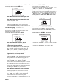 236
236
-
 237
237
-
 238
238
-
 239
239
-
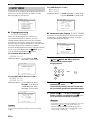 240
240
-
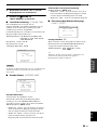 241
241
-
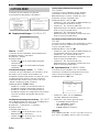 242
242
-
 243
243
-
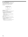 244
244
-
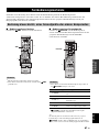 245
245
-
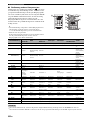 246
246
-
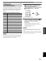 247
247
-
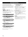 248
248
-
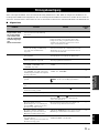 249
249
-
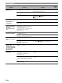 250
250
-
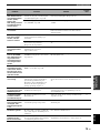 251
251
-
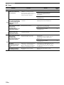 252
252
-
 253
253
-
 254
254
-
 255
255
-
 256
256
-
 257
257
-
 258
258
-
 259
259
-
 260
260
-
 261
261
-
 262
262
-
 263
263
-
 264
264
-
 265
265
-
 266
266
-
 267
267
-
 268
268
-
 269
269
-
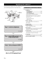 270
270
-
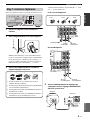 271
271
-
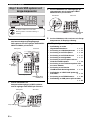 272
272
-
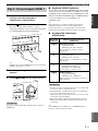 273
273
-
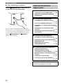 274
274
-
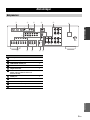 275
275
-
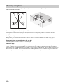 276
276
-
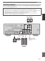 277
277
-
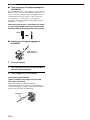 278
278
-
 279
279
-
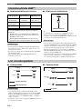 280
280
-
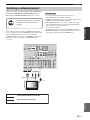 281
281
-
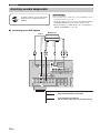 282
282
-
 283
283
-
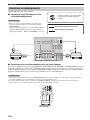 284
284
-
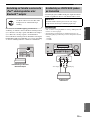 285
285
-
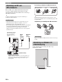 286
286
-
 287
287
-
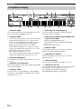 288
288
-
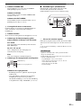 289
289
-
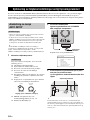 290
290
-
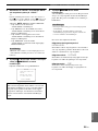 291
291
-
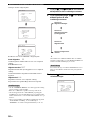 292
292
-
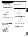 293
293
-
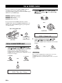 294
294
-
 295
295
-
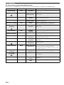 296
296
-
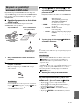 297
297
-
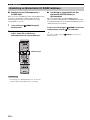 298
298
-
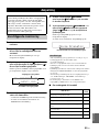 299
299
-
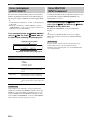 300
300
-
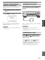 301
301
-
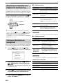 302
302
-
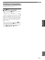 303
303
-
 304
304
-
 305
305
-
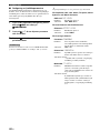 306
306
-
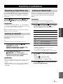 307
307
-
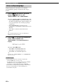 308
308
-
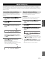 309
309
-
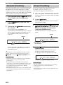 310
310
-
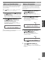 311
311
-
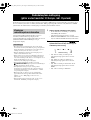 312
312
-
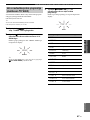 313
313
-
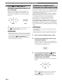 314
314
-
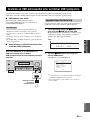 315
315
-
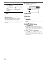 316
316
-
 317
317
-
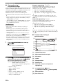 318
318
-
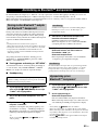 319
319
-
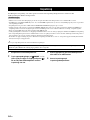 320
320
-
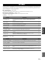 321
321
-
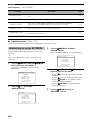 322
322
-
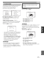 323
323
-
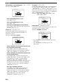 324
324
-
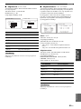 325
325
-
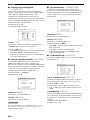 326
326
-
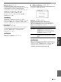 327
327
-
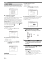 328
328
-
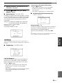 329
329
-
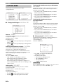 330
330
-
 331
331
-
 332
332
-
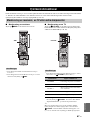 333
333
-
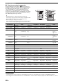 334
334
-
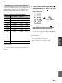 335
335
-
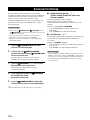 336
336
-
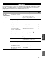 337
337
-
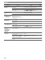 338
338
-
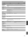 339
339
-
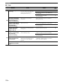 340
340
-
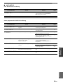 341
341
-
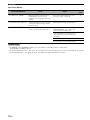 342
342
-
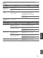 343
343
-
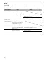 344
344
-
 345
345
-
 346
346
-
 347
347
-
 348
348
-
 349
349
-
 350
350
-
 351
351
-
 352
352
-
 353
353
-
 354
354
-
 355
355
-
 356
356
-
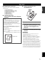 357
357
-
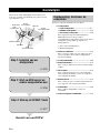 358
358
-
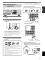 359
359
-
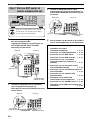 360
360
-
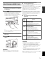 361
361
-
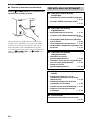 362
362
-
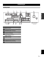 363
363
-
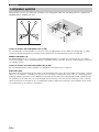 364
364
-
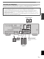 365
365
-
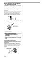 366
366
-
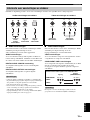 367
367
-
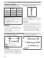 368
368
-
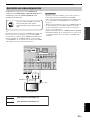 369
369
-
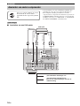 370
370
-
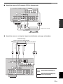 371
371
-
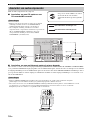 372
372
-
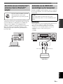 373
373
-
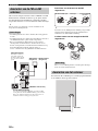 374
374
-
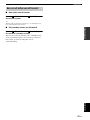 375
375
-
 376
376
-
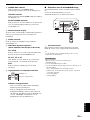 377
377
-
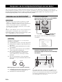 378
378
-
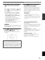 379
379
-
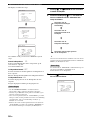 380
380
-
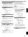 381
381
-
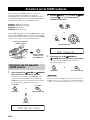 382
382
-
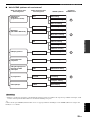 383
383
-
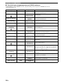 384
384
-
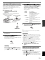 385
385
-
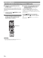 386
386
-
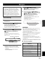 387
387
-
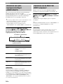 388
388
-
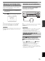 389
389
-
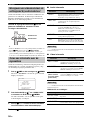 390
390
-
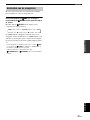 391
391
-
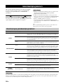 392
392
-
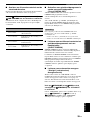 393
393
-
 394
394
-
 395
395
-
 396
396
-
 397
397
-
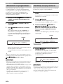 398
398
-
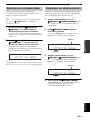 399
399
-
 400
400
-
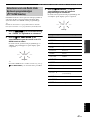 401
401
-
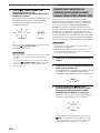 402
402
-
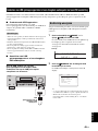 403
403
-
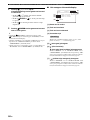 404
404
-
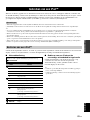 405
405
-
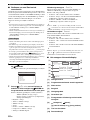 406
406
-
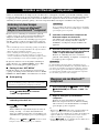 407
407
-
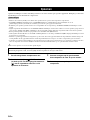 408
408
-
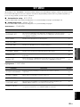 409
409
-
 410
410
-
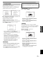 411
411
-
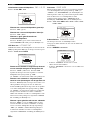 412
412
-
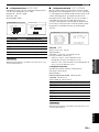 413
413
-
 414
414
-
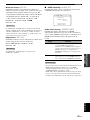 415
415
-
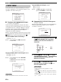 416
416
-
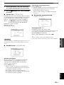 417
417
-
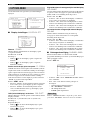 418
418
-
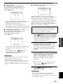 419
419
-
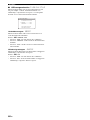 420
420
-
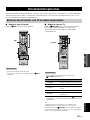 421
421
-
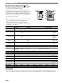 422
422
-
 423
423
-
 424
424
-
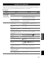 425
425
-
 426
426
-
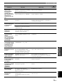 427
427
-
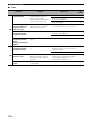 428
428
-
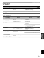 429
429
-
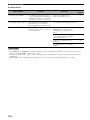 430
430
-
 431
431
-
 432
432
-
 433
433
-
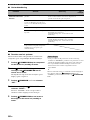 434
434
-
 435
435
-
 436
436
-
 437
437
-
 438
438
-
 439
439
-
 440
440
-
 441
441
-
 442
442
-
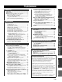 443
443
-
 444
444
-
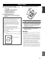 445
445
-
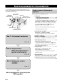 446
446
-
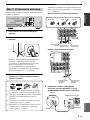 447
447
-
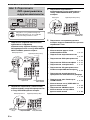 448
448
-
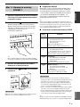 449
449
-
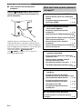 450
450
-
 451
451
-
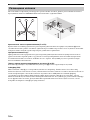 452
452
-
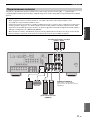 453
453
-
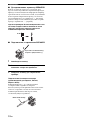 454
454
-
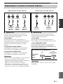 455
455
-
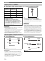 456
456
-
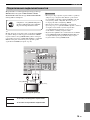 457
457
-
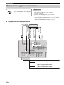 458
458
-
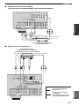 459
459
-
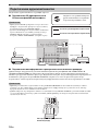 460
460
-
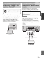 461
461
-
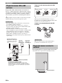 462
462
-
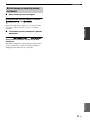 463
463
-
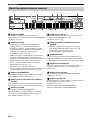 464
464
-
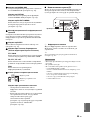 465
465
-
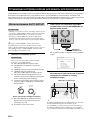 466
466
-
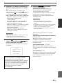 467
467
-
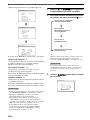 468
468
-
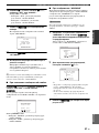 469
469
-
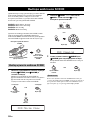 470
470
-
 471
471
-
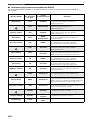 472
472
-
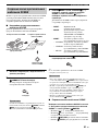 473
473
-
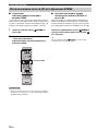 474
474
-
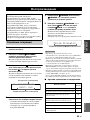 475
475
-
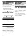 476
476
-
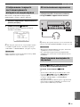 477
477
-
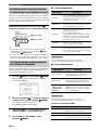 478
478
-
 479
479
-
 480
480
-
 481
481
-
 482
482
-
 483
483
-
 484
484
-
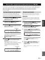 485
485
-
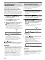 486
486
-
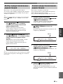 487
487
-
 488
488
-
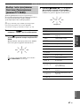 489
489
-
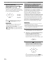 490
490
-
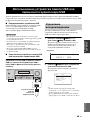 491
491
-
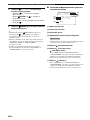 492
492
-
 493
493
-
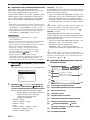 494
494
-
 495
495
-
 496
496
-
 497
497
-
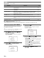 498
498
-
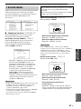 499
499
-
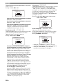 500
500
-
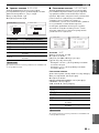 501
501
-
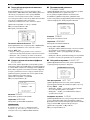 502
502
-
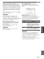 503
503
-
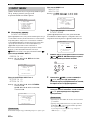 504
504
-
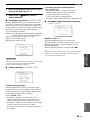 505
505
-
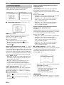 506
506
-
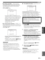 507
507
-
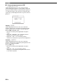 508
508
-
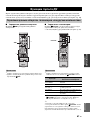 509
509
-
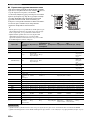 510
510
-
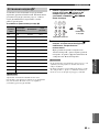 511
511
-
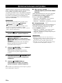 512
512
-
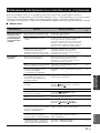 513
513
-
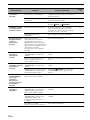 514
514
-
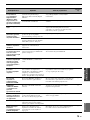 515
515
-
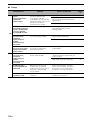 516
516
-
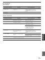 517
517
-
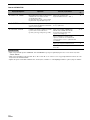 518
518
-
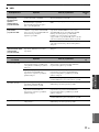 519
519
-
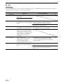 520
520
-
 521
521
-
 522
522
-
 523
523
-
 524
524
-
 525
525
-
 526
526
-
 527
527
-
 528
528
-
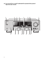 529
529
-
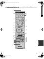 530
530
-
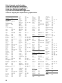 531
531
-
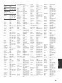 532
532
-
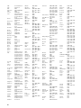 533
533
-
 534
534
-
 535
535
-
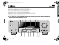 536
536
-
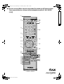 537
537


Yamaha RX-V463 Manualul proprietarului
- Categorie
- DVD playere
- Tip
- Manualul proprietarului
în alte limbi
- Türkçe: Yamaha RX-V463 El kitabı
- français: Yamaha RX-V463 Le manuel du propriétaire
- русский: Yamaha RX-V463 Инструкция по применению
- English: Yamaha RX-V463 Owner's manual
- suomi: Yamaha RX-V463 Omistajan opas
- Deutsch: Yamaha RX-V463 Bedienungsanleitung
- svenska: Yamaha RX-V463 Bruksanvisning
- dansk: Yamaha RX-V463 Brugervejledning
- Nederlands: Yamaha RX-V463 de handleiding
Lucrări conexe
-
Yamaha RX-V563 Manualul proprietarului
-
Yamaha DRX1 Manual de utilizare
-
Yamaha DRX-2 Manualul proprietarului
-
-
Yamaha RX-A1020 Ghid de instalare
-
Yamaha RX-V1073 Ghid de instalare
-
Yamaha NX-B02 Manualul proprietarului
-
Yamaha RX-V371 Remote Control Code
-
Yamaha HTR-4065 Remote Control Code
-
Alte documente
-
Sharp GX-BT480(BK) Manualul proprietarului
-
Ibiza Sound SPLBOX450 Manualul proprietarului
-
Hama 00173147 Manualul proprietarului
-
-
-
-
LG PJ9 Manual de utilizare
-
ELRO DVR151S Manualul proprietarului
-
Logitech Z607 Manualul utilizatorului
-
Konig Electronic SEC-DVRMON30 Manual de utilizare