Stiga SRC 750 G Manualul proprietarului
- Categorie
- Mini motocultoare
- Tip
- Manualul proprietarului

ISTRUZIONI D’USO IT.....10
OPERATING ISTRUCTIONS E N . . . 1 6
MODE D’EMPLOI FR......22
BEDIENUNGSANWEISUNG DE.......28
INSTRUCCIONES DE USO ES.......34
GEBRUIKSINSTRUCTIES NL......40
INSTRUÇÕES DE UTILIZAÇÃO PT......46
BRUKSANVISNING SV......52
KÄYTTÖOHJEET FI......58
BRUGERVEJLEDNING DA......64
BRUKSANVISNING NO.....70
NÁVOD K OBSLUZE CS....76
INSTRUKCJE OBSŁUGI PL....82
NAVODILA ZA UPORABO SL....88
ИНСТРУКЦИИ ПО ЭКСПЛУАТАЦИИ
RU....94
KEZELÉSI ÚTMUTATÓ HU....100
ΟΔΗΓΙΕΣ ΧΡΗΣΗΣ EL....106
UPUTE ZA UPORABU HR....112
NAUDOJIMO INSTRUKCIJOS LT.....118
EKSPLUATĀCIJAS INSTRUKCIJAS LV.....124
INSTRUCŢIUNI DE UTILIZARE RO...130
ИНСТРУКЦИИ ЗА УПОТРЕБА BG...136
KASUTUSJUHEND ET....142
NÁVOD NA OBSLUHU SK....148
İŞLETIM TALIMATLARI TK....154
УПАТСТВО ЗА КОРИСТЕЊЕ MK...160
UPUTSTVA ZA UPOTREBU SR....166
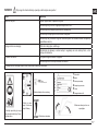
SRC 750 G
SRC 775 RG
SRC 775 RB
SRC 795 RB

1
2
1
2A
2
A
3
4
1
1
5

2B
3
A
1
1
1
1
2
33
2
1

5
4 5
1
3
4
2
4
3
5
A
1
4
1
9
8
1
2
8
5
6
7
4
3

6
3
7 8
2
R
1
4
3
A
4
5
B
1
3
2 A

8/A
1
2
2
3
8/B
1
2
3
A
A
3
1
B
B
4
4
8/C
A
A
1
2
B
3

9
10A
3
1
4
9
7
2
6
5
3
8
10
1
C
D
1
2
3
2

11
1
2
1
3
12
1
2
3
13
A
1
2
4
10B

14
15
3
4
2
1
14
7
12
11
8
5
9
4
10
6
13
3
2
1

10
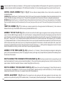
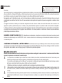
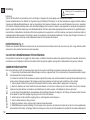
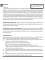
Introduzione
Gentile cliente,
Lei ha acquistato una nuova attrezzatura. La ringraziamo per la ducia accordata ai ns. prodotti e le auguriamo un piacevole utilizzo della sua macchina.
Abbiamo creato queste istruzioni per l’uso allo scopo di assicurare, n dall’inizio, un funzionamento privo d’inconvenienti. Seguite attentamente questi
consigli, avrete la soddisfazione di possedere per molto tempo una macchina che funziona a dovere. Le nostre macchine, prima di essere fabbricate
in serie, vengono collaudate in maniera molto rigorosa e, durante la fabbricazione vera e propria, sono sottoposte a severi controlli. Ciò costituisce, per
noi e per voi, la migliore garanzia che si tratta di un prodotto di riprovata qualità. Questa macchina è stata sottoposta a rigorosi test neutrali, nel paese
d’origine, e risponde alle norme di sicurezza in vigore. Per garantire questo, è necessario utilizzare esclusivamente ricambi originali. L’utilizzatore
perde ogni diritto di garanzia qualora vengono utilizzati ricambi non originali. Con riserva di variazioni tecnico-costruttive. Per informazioni e per
ordinazioni di pezzi di ricambio si prega di citare il numero di articolo e il numero di produzione.
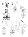
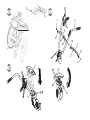
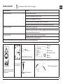
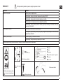
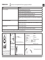
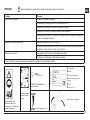
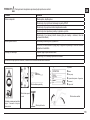
Dati per l’identicazione (Fig.1) L’etichetta con i dati della macchina e il numero di matricola è nella parte anteriore del telaio segnata con
la freccia. Nota - Nelle eventuali richieste di Assistenza Tecnica o nelle ordinazioni delle Parti di Ricambio, citare sempre il numero di matricola della
motozappa interessata.
Condizioni di utilizzazione - Limiti d’uso La motozappa è progettata e costruita per eseguire operazioni di zappatura del terreno. La
macchina deve lavorare esclusivamente con attrezzi e con ricambi originali. Ogni utilizzo diverso da quello sopra descritto è illegale; comporta, oltre al
decadimento della garanzia, anche un grave pericolo per l’operatore e per le persone esposte.
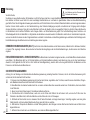
Norme di sicurezza
Attenzione: prima del montaggio e la messa in funzione leggere attentamente il libretto istruzione. Le persone che non conoscono le norme
di utilizzazione non possono usare la macchina.
1 - L’ uso della macchine è vietato ai minori di 16 anni e alle persone che hanno assunto alcol, medicine o droghe.
2 - La macchina è stata progettata per essere utilizzata da un solo operatore addestrato. L’utilizzatore dell’apparecchio è responsabile di danni
a r r e c a t i a d a l t r e p e r s o n e e d a l l e l o r o p r o p r i e t à ; c o n t r o l l a r e c h e a l t r e p e r s o n e , s o p r a t u t t o i b a m b i n i s t i a n o l o n t a n i d a l l a z o n a d i l a v o r o ( 1 0 m e t r i ) .
3 - Togliere i corpi estranei dal terreno prima di iniziare le operazioni di fresatura . Lavorare solo alla luce del giorno oppure in presenza di una
buona illuminazione articiale.
4 - Non mettere in moto la macchina quando si è davanti alla fresa, né avvicinarsi ad essa quando è in moto. Tirando la corda di avviamento
del motore, le frese e la macchina stessa devono rimanere ferme (se le frese girano intervenire sul registro di regolazione del tendi-cinghia).
5 - Durante il lavoro, per maggiore protezione, vanno indossate calzature robuste e pantaloni lunghi. Fare attenzione, perchè il pericolo di ferirsi
le dita o i piedi con la macchina in funzione, è molto elevato. Camminare, non correre, durante il lavoro.
6 - Durante il trasporto della macchina e tutte le operazioni di manutenzione, pulitura, cambio degli attrezzi, il motore deve essere spento.
7 - Allontanarsi dalla macchina non prima di aver spento il motore.
8 - Non avviare la macchina in locali chiusi dove si possono accumulare esalazioni di carbonio.
9 - AVVERTENZA La benzina è altamente inammabile, conservare il carburante in appositi recipienti. Non fare il pieno di benzina in locali
chiusi né con il motore in moto. Non fumare e fare attenzione alle fuoriuscite di combustibile dal serbatoio. In caso di fuoriuscita non tentare di
Pericolo grave per l’incolumità
dell’operatore e delle persone esposte.
Istruzioni d’uso originali
I

11
avviare il motore, ma allontanare la macchina dall’area interessata evitando di creare fonti di accensione nché non si sono dissipati i vapori
della benzina. Rimettere a posto correttamente i tappi del serbatoio e del contenitore della benzina. Non aprire il tappo della benzina con
motore acceso o quando è caldo.
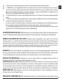
10 - Attenzione al tubo di scarico. Le parti vicine possono arrivare a 80°. Sostituire i silenziatori usurati o difettosi.
11 - Non lavorare sui pendii eccessivamente ripidi ed usare la massima precauzione nell’invertire il senso di marcia o nel tirare verso sé stessi
la macchina.
12 - Prima di iniziare il lavoro con la macchina procedere ad un controllo visivo e vericare che tutti i sistemi antinfortunistici, di cui essa è
dotata, siano perfettamente funzionanti. E’ severamente vietato escluderli o manometterli. Sostituire le lame danneggiate o usurate per lotti
campione per mantenere il bilanciamento.
13 - Ogni utilizzo improprio, le riparazioni effettuate da personale non specializzato o l’impiego di ricambi non originali, comportano il
decadimento della garanzia e il declino di ogni responsabilità della ditta costruttrice.
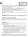
DISPOSITIVO DI SICUREZZA (Fig. 14) Tutte le motozappe sono dotate di dispositivo antinfortunistico. Detto dispositivo causa il disinnesto
automatico della trasmissione quando si rilasciano le relative leve di comando (2 Marcia avanti e 3 Retro marcia).
NOTE PER IL LAVORO CON LA MOTOZAPPA A motore avviato, appoggiare i coltelli sul terreno e, tenendo saldamente la motozappa,
inlare nel terreno il timone. Abbassare la leva avanzamento (Fig. 14 part. 2) sul manubrio per far penetrare la fresa nel terreno. Sollevando leggermente
la fresa mediante il manubrio, la motozappa si muove in avanti. Il timone durante il lavoro deve rimanere sempre inlato nel terreno. Applicazioni:
Lavorazione di terreni leggeri o di media pesantezza. Lavorazione del terreno (fresatura/sminuzzamento). Dissodamento del terreno (eliminazione
infestanti) , incorporamento di compost o fertilizzanti, ecc. Attenzione: la motozappa non è adatta per la lavorazione di terreni ricoperti di cotica erbosa
compatta/prato. Se ne sconsiglia inoltre l’uso sui terreni pietrosi.
TRASPORTO
Per la movimentazione è previsto l’uso di carrello elevatore. Le forche, allargate al massimo consentito, vanno inserite negli appositi spazi del pallet.
La massa della macchina è indicata nella etichetta della marcatura. Tramite la ruota di trasferimento (Fig. 14 part. 8) è possibile portare la motozappa
nella posizione di impiego in modo pratico e comodo. Prima di trasportare la macchina spegnere il motore.
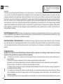
MONTAGGIO DELLA MOTOZAPPA La motozappa viene consegnata a destinazione, salvo accordi diversi, smontata e sistemata in un
adeguato imballaggio. Per completare il montaggio della motozappa osservare la seguente procedura:
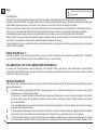
Ruota di trasferimento (Fig. 2, 2/A e 2/B) Prelevare dalla scatola imballo il supporto ruotino completo di ruota (1) ed inserirlo nella sede
anteriore del telaio (A). Inlare la molla (2), bloccarla con la rondella (3) e la copiglia (4) nel foro del supporto ruotino.
Nella g. 2/A il supporto ruotino è rappresentato in posizione di trasporto.
Per passare alla posizione di lavoro tirare verso di sé il supporto ruotino (1) e ruotarlo verso destra no a quando si blocca. Vedere rappresentato in
g. 2/B.
La molla, la rondella e la copiglia sono all’interno della busta accessori.
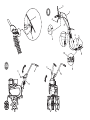
Sperone (Fig. 3) Inserire lo sperone (1) in corrispondenza del foro del telaio (A). Bloccare con la rondella (2) e con la spilla a R (3) presenti
all’interno della busta accessori.
I

12
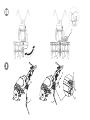
MONTAGGIO MANUBRIO (Fig. 4) P e r m o n t a r e i l m a n u b r i o ( 1 ) s u l t e l a i o d e l l a m o t o z a p p a e s e g u i r e l a s e g u e n t e p r o c e d u r a :
Nel foro superiore fare passare la vite (2) nel passalo (3) al cui interno sono già inseriti i cavi, quindi bloccarla con il dado (4). Nell’asola inferiore
utilizzare le viti (5) all’interno delle manopole (6) e rondelle (7). Tutti questi pezzi per il montaggio manubrio, ad eccezione del passalo (3), sono
presenti nella busta accessori all’interno della scatola imballo. Per ssare denitivamente il manubrio (1) al relativo supporto (8) occorre abbassare
la leva (9).
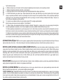
MONTAGGIO CAVI COMANDO (Fig. 5 e Fig. 6) I due cavi sono già montati sulla macchina e occorre collegarli alle rispettive leve.
MARCIA AVANTI (Fig. 5) Inserire il lo (1) con il terminale a T nell’asola (2) della leva (3) premontata sul manubrio. Posizionare il terminale a T (4)
nella sede centrale della leva (3) e dare uno strappo deciso per bloccarlo. Successivamente incastrare il terminale di plastica (5) nell’apposita sede (A)
della leva, facendo pressione verso il basso.
RETRO MARCIA (Fig. 6): Inserire il lo (1) contrassegnato dall’etichetta R e con il terminale cilindrico, nell’asola (2) della leva (3) premontata sul
manubrio. Posizionare il terminale cilindrico (4) nella sede centrale (A) della leva (3) e dare uno strappo deciso per bloccarlo. Successivamente
inserire il registro del lo (5) nell’apposita sede (B) della leva.
MONTAGGIO ACCELERATORE (Fig. 7) Il lo acceleratore è già montato sia sul motore che all’interno del dispositivo acceleratore (1) . Tale
dispositivo va ssato nel foro (A) della stegola con la vite (2) e bloccato con il dado (3).
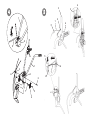
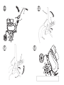
MONTAGGIO DELLE FRESE A ZAPPETTE (Fig. 8) Pulire i mozzi delle frese e l’albero porta-frese; spalmare una piccola quantità di
grasso per facilitare il montaggio e la futura rimozione delle frese. Versione con motore B&S 950 (g. 8-1): inserire la fresa (1) badando che i coltelli
abbiano l’aflatura rivolta verso l’anteriore della macchina e bloccare con due spinotti (2). Aggiungere l’allargamento fresa (3) e ssare anche quest‘
ultimo con uno spinotto (2). Inne bloccare il disco proteggi piante (4) con vite (5) e dado (6). Ripetere la stessa operazione per la fresa sull’altro lato.
Versione con altri motori (g. 8-2): la fresa (1) risulta già montata con nr. 2 viti ed altrettanti dadi, quindi occorre solo aggiungere l’allargamento fresa
(3) e bloccarlo con uno spinotto (2). Fissare il disco proteggi piante (4) con vite (5) e dado (6). Ripetere la stessa operazione per la fresa sull’altro lato.
N.B. Occorre montare lo spinotto come rafgurato nel quadretto centrale, cioè con il fermo di protezione girato nel senso di rotazione delle frese, in
modo tale da impedire che durante il lavoro si possa aprire.
MONTAGGIO ALLARGAMENTO RIPARO FRESA (Fig. 8/A) Solo per motozappe con frese da cm. 75. Prelevare dalla scatola
imballo l’allargamento riparo fresa (1) con già premontate le viti (2). Montarlo facendo coincidere le viti (2) con i dadi a gabbia (3). Ripetere la stessa
operazione con l’allargamento dall’altro lato della fresa.
MONTAGGIO TRAVERSINO STEGOLA (Fig. 8/B) Prelevare dalla busta accessori i due traversini (1) e posizionarli facendoli combaciare
uno sopra e uno sotto al manubrio (2). Successivamente ssarli al medesimo facendo passare le viti (3) nei due fori (A) del traversino superiore e nei
fori (B) del traversino inferiore. Serrare inne con i dadi (4).
MONTAGGIO COFANO STEGOLA (Fig. 8/C) Prelevare dalla scatola imballo il cofano (1). Posizionarlo facendo incastrate le sedi (A) sulla
parte inferiore del manubrio (2) . Ruotare il cofano come in gura facendo attenzione a fare coincidere la sede (B) con la leva (3). Il cofano è montato
correttamente quando il gancio (C) del cofano (1) è agganciato al perno (D) del manubrio (2).
I

13
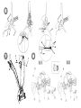
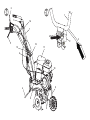
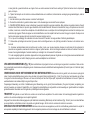
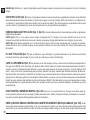
REGISTRAZIONE DEI COMANDI (Fig. 9) Attenzione! La fresa deve iniziare a girare non prima di avere agito sui rispettivi comandi. Questo
si ottiene intervenendo sui registri dei li (1 MA) e (2 RM). Inoltre la leva (3) che comanda la marcia di zappatura, deve avviare la fresa solo dopo aver
compiuto metà della propria corsa. Quando la leva (3) della marcia avanti e la leva (4) della retromarcia sono a ne corsa, cioè in posizione di lavoro,
le rispettive molle di carico (5 e 6) si devono allungare di circa 8-10 mm. Se ciò non avviene è possibile effettuare un’ulteriore registrazione.
MARCIA AVANTI: avvitare o svitare il registro (7) o (8) sul lo (1).
RETRO MARCIA : avvitare o svitare il registro (9) o (10) sul lo (2).
REGOLAZIONE MANUBRIO (Fig.10A - 10B) Il manubrio della motozappa è orientabile sia lateralmente che in altezza. E’ consigliabile,
prima di iniziare qualsiasi tipo di lavoro, regolare il manubrio in base alle proprie esigenze.
REGOLAZIONE LATERALE (Fig. 10A): l’orientamento laterale del manubrio permette all’operatore di non calpestare il terreno già zappato e non
danneggiare la vegetazione. Procedere alzando la leva (3) per sbloccare il manubrio (2) dal supporto (1). Ruotare il manubrio (2) dalla parte desiderata
ed abbassare la leva (3) per bloccarlo.
REGOLAZIONE IN ALTEZZA (Fig. 10B): per poter sbloccare il manubrio (2) occorre ruotare le manopole (4) per allentarle. Sollevare o abbassare il
manubrio nella posizione desiderata (regolazione standard l’altezza dei anchi) e, per confermare l’esatta posizione, bloccare le due manopole.
ISTRUZIONI D’USO Dopo le operazioni di montaggio e regolazione la motozappa è pronta per lavorare.
- Regolare il manubrio all’altezza più adatta al lavoro da eseguire. (Vedi g.10)
- P ri ma di av vi ar e i l m oto re co nt ro ll ar e s em pre ch e l a m ac ch in a s ia in p er fe tt e c on di zi on i di fu nz io na me nt o.
- Attenzione: la macchina viene consegnata con il motore senza olio. Il serbatoio ha una capacità di circa 0,5 Kg e va riempito no al livello indicato. In
ogni caso leggere sempre attentamente il manuale istruzioni del motore.
- Non modicare la taratura del regolatore di velocità di rotazione del motore e non far raggiungere ad esso una condizione di sopra
velocità.
- IMPORTANTE : al primo utilizzo della macchina è assolutamente necessario vericare che all’interno del telaio sia presente l’olio di lubricazione.
Non avviare la macchina senza avere prima fatto questo controllo.
- Terminato il montaggio accendere la motozappa e controllare che, portando l’acceleratore in posizione stop, il motore si spenga correttamente.
- Messa in moto del motore (Fig.14) Aprire il rubinetto del carburante (per i motori provvisti), posizionare su START la levetta dell’acceleratore posto sul
manubrio (part.1). Se il motore è freddo, azionare il dispositivo di starter sul carburatore, afferrare la maniglia di avviamento (10) e dare uno strappo energico.
Avviato il motore riportare, dopo i primi scoppi, lo starter nella posizione di riposo.
- Marcia avanti (Fig. 11) Per azionare la marcia avanti impugnare il manubrio (1) e premere il pulsante di sicurezza (2) che impedisce l’innesto
accidentale delle frese. Abbassare la leva (3) per tutta la sua corsa.
- Marcia indietro (Fig. 12) Per azionare la leva retro marcia o marcia indietro, impugnare il manubrio (1) premere il pulsante di sicurezza (2) che
impedisce l’innesto accidentale delle frese. Tirare la leva (3) per tutta la sua corsa.
Questa motozappa è progettata per ridurre al minimo le emissioni di vibrazioni e rumore, tuttavia è buona norma intervallare lavori di lunga durata con
piccole pause. In caso di utilizzo prolungato si consiglia l’uso di protezioni acustiche.
- Fine lavoro : terminato il lavoro, per arrestare il motore, portare la leva acceleratore (Fig.14 part.1) nella posizione di stop.
I

14
SOSTITUZIONE OLIO DEL CAMBIO (solo per motori/cambi a caldo) (Fig. 13) In linea di massima si dovrebbe sostituire l’olio
ogni 100 ore di lavoro. (Viscosità olio SAE 80). Cambio olio: a) Smontare lo sperone b) Allentare il tappo a vite. - c) Collocare la macchina in posizione
inclinata e aspirare l’olio tramite una siringa. - d) Introdurre l’olio nuovo nella quantità di circa 0,5 lt. Per controllare il giusto livello è necessario inclinare
la macchina; l’olio dovrà iniziare ad uscire dal foro poco prima che la macchina (con il punto A) tocchi terra. - e) Richiudere il foro di riempimento con
il tappo a vite (1).
IMPORTANTE! Per evitare l’inquinamento delle falde acquifere, l’olio esausto non deve essere gettato in scarichi fognari o canali idrici. Depositi per
l’olio esausto sono ubicati presso tutti i distributori di benzina, oppure in discariche autorizzate secondo le normative comunali del Comune di residenza.
RIMESSAGGIO E MANUTENZIONE PERIODICA ( Fig.15) Mantenere serrati tutti i dadi, i bulloni e le viti per garantire il funzionamento
della macchina in condizioni di sicurezza. Controllare periodicamente il serraggio del manubrio (1) al supporto (2). Nel caso il serraggio non fosse
garantito abbassare la leva (3) ed avvitare il dado (4). Un corretto serraggio dei componenti aiuta a ridurre le vibrazioni della macchina.
Svuotare il serbatoio della benzina sempre all’esterno. Lasciare raffreddare la macchina prima di immagazzinarla e comunque non riporla con benzina
nel serbatoio all’interno di un edicio, dove i vapori possono raggiungere una amma libera o una scintilla. Per ridurre il pericolo di incendio mantenere
il motore, il silenziatore e la zona di immagazzinamento della benzina liberi da foglie, erba e grasso in eccesso.
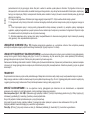
DESCRIZIONE DEI COMANDI (Fig. 14) 1. Levetta comando acceleratore a mano - 2. Leva comando avanzamento e comando di zappatura
(dispositivo antinfortunistico) - 3. Leva comando retromarcia - 4. Sperone per regolazione fresatura (unica posizione) - 5. Frese (con allargamento) - 6.
Manopola di serraggio manubrio/telaio - 7. Manubrio - 8. Ruota di trasferimento - 9. Riparo fresa - 10. Maniglia per avviamento a strappo (dispositivo
auto-avvolgente) - 11. Motore – 12. Leva bloccaggio/sbloccaggio manubrio - 13. Supporto manubrio. - 14. Traversino
CARATTERISTICHE TECNICHE Motore: per informazioni vedere la pubblicazione specica. Trasmissione: Primaria a cinghia - Secondaria
a catena. La velocità massima di rotazione della fresa è di 140 giri/min. circa. Cambio: marcia avanti o marcia avanti + retromarcia. Dimensioni:
Lunghezza massima 1,35 m. Larghezza massima 0,50 m (SRC 750 G), 0,75 m (SRC 775 RG/RB), 0,95 m (SRC 795 RB). Altezza 1,00 m. Dimensioni
imballaggio: lunghezza 80 cm - larghezza 53 cm - altezza 69 cm.
RUMORE AEREO E VIBRAZIONI Valore di pressione acustica al posto di lavoro secondo EN 709 Leq = 88,5 dB(A), valore d’incertezza nella
misura K = ±0,8 dB(A). Valore di potenza acustica secondo En709 Lwa = 96,1 dB(A), valore d’incertezza nella misura K = ±0,9 dB(A). Vibrazioni alle
stegole secondo EN 709 e ISO 5349= 5,39 m/s², valore d’incertezza nella misura K = ±0,36 m/s².
ACCESSORI
Allargamento riparo fresa a 75 cm (solo per SRC 750 G), ruote di trasferimento, rincalzatore ad ali sse, sperone registrabile.
I

15
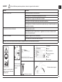
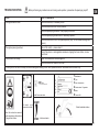
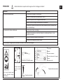
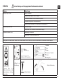
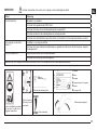
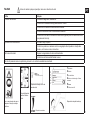
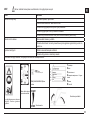
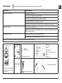
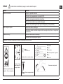
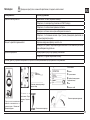
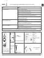
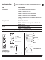
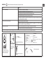
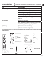
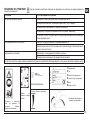
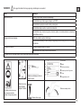
GUASTI Prima di effettuare qualsiasi operazione, staccare il cappuccio della candela !
Guasto Rimedio
Il motore non si avvia Carburante esaurito, fare rifornimento.
Controllare che l’acceleratore sia posizionato su START.
Controllare che il cappuccio candela sia ben inserito.
Controllare lo stato della candela ed eventualmente sostituire.
Controllare che il rubinetto del carburante sia aperto (solo per i modelli di motore in cui
è previsto il rubinetto).
La potenza del motore diminuisce Filtro aria sporco, pulirlo.
Controllare che sassi o residui di terra e vegetazione non frenino la rotazione delle
frese, nel caso rimuoverli.
Le frese non ruotano Regolare i registri del cavo trasmissione.
Controllare che le frese siano ssate all’albero.
Nel caso non si riesca a porre rimedio al guasto, rivolgersi ad un centro di assistenza autorizzato.
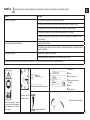
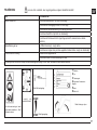
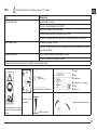
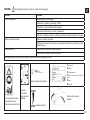
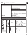
Leggere il manuale prima di
usare la macchina - Attenzione:
rotazione fresa
Etichetta innesto
Marcia avanti e Re-
tromarcia.
Etichetta indicazione lo retromarcia
1 Costruttore
2 Modello
3 Anno di costruzione
4 Numero di serie articolo –
Progressivo
5 Massa
6 Potenza in kW
Etichetta acceleratore
Etichetta rotazione stegola
I

16
Introduction
Dear Customer:
Thank you for your condence in purchasing our products. We wish you to enjoy using our machines.
The following working instructions have been issued to ensure you a reliable running from the beginning. If you carefully follow such information the
machine will operate with complete satisfaction have a long service life.
Our machines are tested under the most severe conditions before being put into production and are subjected to strict continuous tests during
manufacturing stages.
The present unit has been tested in the country of origin by independent testing authorities in accordance with strict work norms and safety standards.
When required, only original spare parts must be used to maintain guaranteed function and safety levels.
The operator forfeits any claims which may arise, if the machine shows to be tted with components other than original spare parts. Subject to changes
in design and construction without notice.
For any questions or further information and spare part orders, we need to be informed of the unit serial number printed on the side of the machine.
IDENTIFICATION DATA (Fig. 1)
The label showing the unit references and the serial number is placed in the front frame side of it and it is shown by an arrow. Note - Always state your
motor cultivator serial number when you need Technical Service or Spare Parts.
CONDITIONS OF USE AND LIMITATIONS OF USE
This motor-hoe is designed and built to hoe the land. The motor-hoe must only be used with original equipment and spares. Any use other than those
described above is prohibited and will involve, in addition to cancellation of the warranty, serious risk for the operator and bystanders.
SAFETY PRECAUTIONS
Attention: Before assembly and putting into operation, please read the operating instruction carefully. Persons not familiar with these
instructions should not use the machine.
1- Persons who are not familiar with the operating manual, as well as children, adolescents under the age of 16 and persons under the
inuence of alcohol, drugs or medication must not operate the mower.
2 - The unit was designed in order to be used by 1 operator only. The person using the mower is responsible for any accidents involving other
persons or their property. When operating the machine, the user should ensure that no others, particularly children, are standing in the area.
3 - Before starting to mill, remove any foreign bodies from the soil. Work only in daylight or in good articial light.
4 - Do not start the machine if standing in front of the rotary cutter, neither get near the machine when working. If pulling the starter short rope,
the rotary cutter and the machine have to standstill (if rotation is experienced, take action on the belt stretcher control nut).
5 - During working operations, for protection purposes, it is recommended to wear technical/strong shoes and long trousers. Be careful ,
because when machine is operating the danger to be wounded in the toes or feet is really high. Walk, never run with the machine.
6 - During the machine transport and all the maintenance, cleaning, equipment change operations, the engine must be switched off.
7 - Before leaving the machine, please switch the engine off.
8 - Do not switch the machine on in closed rooms/areas where you can have carbon monoxide exhalations.
Serious risk for operator and bystander
safety.
EN

17
9 - WARNING !! The petrol/gasoline is highly inammable: Don’t ll the tank neither in closed areas, nor when engine is on, don’t smoke and
be careful to the petrol/gasoline loss from the tank. In case of leak, don’t try to switch the engine on but move the machine away from the area
in order to avoid ignition source until the gasoline vapours fade away. Re-place the tank caps and the gasoline box.
10 - Keep attention to the exhaust pipe. The parts near the pipe can reach 80°C.
Replace the defective and/or worn out silencers Burn hazards !!!.
11- Don’t use the motor hoe on steep slopes: it could overturn!. On slope it is recommended to work crosswise, neither in slope nor in descent
and be vary careful during any change of direction.
12 - Before putting the machine into operations, check it visually and make sure all the accident prevention measures are working. It is
absolutely forbidden to exclude and/or to tamper with them. Replace worn or damaged elements.
13 - In case the machine is incorrectly used, and/or the repairs are performed by non-authorized technical staff, and/or tted by spare parts
other then original ones: any use other than that described above is prohibited and will involve the cancellation of the warranty and the refuse
all responsibility from the manufacturer.
SAFETY FEATURE (Fig. 14) All motor-hoes are provided with a safety feature which acts. The device causes the transmission to disconnect
automatically anytime the respective control levers are released (2 Forward speed – 3 Reverse speed).
NOTES ON HOW TO WORK WITH THE MOTOR-HOE With the engine running, rest the tines on the ground, and rmly holding the
motor-hoe, insert the spur into the soil. Lower the clutch lever on the handlebar to allow the disks to bite into the soil. The motor-hoe will move forwards
when the handlebars are used to slightly lift the disks. The spur arm must always remain in the soil during work. Uses: Light or medium textured soil
working. Soil working (hoeing/breaking-up). Soil tillage (weeding). Ploughing in compost or fertilizers, etc. Attention: The motor-hoe is unsuitable for
working in soils covered by thick grass/lawns. It is also unadvisable to use the implement on stony soils.
TRANSPORT A forklift truck should be used to move the machine. The forks should be opened as far as possible and inserted into the pallet. The
weight of the machine is given on the Manufacturer’s data plate together with the other technical information. Motor-hoe can be transported to given
place by means of transport wheel (Fig 14 part. 8). Switch off the engine before transporting the machine.
HOW TO ASSEMBLE YOUR MOTOR-HOE Unless otherwise agreed, the motor-hoe is delivered disassembled and placed in a packing
case. For assembly to be completed, the step by step procedure is as follows :
TRANSFER WHEEL (Fig. 2 A and 2 B) Take from the packing box the support wheel complete with wheel (1) and insert it in the front seat of the frame
(A). Fit the spring (2) and secure it with the washer (3) and the cotter pin (4) into the housing hole. The wheel support is in the transport position as
shown in Fig. 2A. To shift to work position pull it towards the wheel support (1) and turn it to the right until it stops. See g. 2 B. The spring, washer and
cotter pin can be found inside the bag accessories.
SPUR (Fig. 3) Insert the spur (1) in correspondence of the hole of the frame (A). Secure with washer (2) and with the R pin (3) you can nd in the
accessories bag.
HANDLEBAR ASSEMBLY ( Fig. 4) : To assemble the handlebar (1) on the tiller frame, perform the following steps:
In the upper hole to pass the screw (2) in the grommet (3) with already entered the control cables and then secure it with the nut (4). Use the lower slot
EN

18
screws (5) inside of the knobs (6) and washers (7). All these pieces for mounting handlebar with the exception of the grommet (3), are present in the
envelope accessories inside the packaging box. To t denitively the handlebar (1) to the corresponding support (8) you need to lower the lever (9).
CONTROL CABLES ASSEMBLY (Fig. 5 - Fig. 6): The two cables are already installed on the unit and must be connected to the
corresponding levers.
FORWARD (Fig. 5) Insert the wire (1) with the terminal T-slot (2) of the lever (3) pre-mounted on the handlebar. Place the cylindrical terminal (4) into
the seat of the lever (3) and give a rm tug to lock it. Then pinch the wire adjuster (5) into the seat (A) of the lever, by doing downward pressure.
REVERSE (Fig. 6): Insert the wire (1) marked with R label and the cylindrical terminal into the slot (2) of the lever (3) pre-assembled on the handlebar.
Place the cylindrical terminal (4) into the central seat (A) of the lever (3) and give a rm tug to lock it. Then insert the log thread (5) into place (B) of the
lever.
THROTTLE ASSEMBLY (Fig. 7) The throttle wire is already mounted both on the engine inside the throttle device (1). Such a device is
fastened in the hole (A) of the handlebar with the screw (2) and locked with the nut (3).
ASSEMBLY THE HOE TILLER (Fig. 8) Clean the tiller hubs and the tiller-shaft; apply some grease to make mounting and tiller removal
easier in the future. B&S 950 engine model (g. 8-1): insert the rotavator (1) making attention the knives have the sharpening side turned to the front
part of the machine and block the rotavator with two pins (2) assembling the extra-wide tines (3) and x it with 1 pin as well (2). Then block the tree saver
disk (4) with 1 screw (5) and 1 nut (6). Repeat the same operation for the rotavator on the other machine side. Other engines (g. 8-2): the rotavator
(1) is already assembled with nr. 2 screws and the same number of nuts so you only need to assemble the extra-wide tines (3) and block it with pin (2)
and x the tree saver disk (4) with screw (5) and nut (6). Repeat the same operation for the rotavator on the other machine side. N.B. = please note it
is necessary to assemble the pin as shown in the picture placed in the centre of the page, i.e. , with the protection stopping device turned in the same
direction the rotavators are turning, in order to avoid the pin to open during working operations.
ASSEMBLY OF THE TINES GUARD (Fig. 8/A) Only tillers with cm. 75 rotavator. Remove the packing box enlargement widening tines
guard (1) with pre-assembled screws (2). Mount it by aligning the screws (2) with cage nuts (3). Repeat the same operation with the widening tines of
the other side of the rotavator.
HOW TO ASSEMBLY THE CROSSBAR ON THE HANDLEBAR (Fig. 8/B) Take the two crossbars from the loose parts bag (1) and
place them making them t one above and one below the handlebar (2). Then secure the same by passing the screws (3) into the two holes (A) of the
upper crossbar and into the holes (B) of the lower crossbar Finally, tighten with the nuts (4).
HOW TO ASSEMBLE THE HANDLEBAR COVER (Fig. 8/C) Take out the cover from the packaging (1). Place it tting the seats (A)
on the lower part of the handlebar (2). Turn the cover as in g. being careful to make the seat (B) to match with the lever (3). The cover is properly
installed when the hook (C) of the cover (1) is coupled to the pin (D) of the handlebar (2).
CONTROL ADJUSTMENT : (Fig. 9) Attention! The rotavator has to start working only after having operated on the control levers. Such
operation can be performed by acting on the handlebar cables (1 Forward speed) 2 (Reverse speed) register. Furthermore the lever controlling the
EN

19
digging speed (3) should start the rotavator only after having performed half its way. When the lever (3) and the lever (4) are held toghether, i.e. on
working operation , the belt stretcher load-spring for forward speed (5 and 6) should be extended for about 8-10 mm. If the handlebar register is not
enough to obtain any conditions , please go on another adjustment.
FORWARD: screw or unscrew the adjuster (7) or (8) on the wire (1).
REVERSE: screw or unscrew the adjuster (9) or (10) on the wire (2).
HANDLEBAR ADJUSTMENT (Fig. 10A - 10B) The motor-hoe handlebar can be both side and height adjusted. Before starting any work
it is a good standard operating procedure to adjust the handlebar to the operator’s requirements so that the machine could be easily handled.
LATERAL ADJUSTMENT (Fig. 10A) : The lateral inclination of the handlebar allows the operator to keep off the cultivated ground and not to squash
the vegetation around. Go on raising the lever (3) to unlock the handlebar (2) from the support (1). Turn the handlebar to the desired part and lower
the lever (3) to lock it.
HEIGHT ADJUSTMENT (Fig. 10B) : in order to unlock the handlebar (2) you need to turn the handles (4) to loosen them .
Raise or lower the handlebar in the desired position ( the standard adjustment is at the sides height/level). To settle the right position, tighten the 2
handles.
INSTRUCTIONS Following the assembly & adjustment operations the motor-hoe is ready to start working.
- Adjust the handlebar to the requested position/height (see g. 10).
- Before switching the engine on, carefully check if the motor-hoe is in perfect good repair.
- Attention: the motor-hoe is delivered without the oil into the engine. The tank has got a capacity for about 0,5 kg. and should be lled in up to the
indicated level. In any case the operator should always carefully read the engine instructions manual.
- D o n o t c ha ng e t he ca li br at io n o f t he sp ee ds co nt ro l r ot at io n d ev ic e o f t he en gi ne in or de r n ot to ov er -s pe ed it .
IMPORTANT : at the rst use of the machine it is absolutely necessary to verify that inside the chassis to be present the lubrication oil. Do no start the
unit/machine on before having done such control.
- When you have nished the assembly, switch the motor-hoe on and check , bringing the accelerator to stop position , the engine to shut completely
down.
- How to switch the engine on (Fig.14): Open the fuel cap (for the engine equipped like this), push to START the accelerator lever on the handlebar (1).
If the engine is cold, operate the starter device on the carburettor, bring the starter handle (10) and pull energetically.
When the engine is on, after some bursts/bangs, put the starter again at rest position.
- Forward speed (g.11): Grip the handlebars (1) and press the safety device (2) which is preventing the accidental tines connection. Lower the
forward lever (3) all its way long.
- Reverse speed (Fig. 12): Grip the handlebars (1) and press the safety device (2) which is preventing the accidental tines connection. Pull the reverse
lever (3) all its way long.
The present machine has been projected in order to lower to the minimum the vibrations and noise levels. Anyhow we can advise you to stop working
any now and then in case you would need to perform/work for a long period.
- Stop working operation : To stop the work, switch the engine off, bring the accelerator lever (Fig. 14 part 1) into stop position.
GEAR BOX OIL CHANGE (only when engine/gear box is working using a hot device) (Fig. 13) As a general rule the
oil should be changed after every 100 work hours (oil viscosity SAE 80). To change oil: a) Remove the spur. b) Unscrew the screw cap. - c) Tilt the
EN

20
machine and intake the oil through a syringe. - d) Pour in about 0,5 l. of new oil. Tilt the machine to check that level is correct. The oil should begin to
ow from the hole just before the machine touches the ground (with point A) - e) Replace the ller screw cap (1).
ATTENTION! The used oil must not be drained into the sewer system or waterworks. In order to prevent any pollution to the water-table. Most
garages have used oil deposits, or use the authorized deposits according to your local authority regulations.
GARAGING AND SCHEDULED MAINTENANCE (Fig. 15) Keep attention that all the nuts, screws and bolts are tightened in order to
guarantee a good machine working on safety conditions. Leave the machine to cool before garaging anyhow don’t room it if the tank still contains some
fuel as the vapours could reach some blazes or sparks. To lower the re danger , keep the engine , the silencer and the fuel area free from leaves ,
grass or greasy substances. Periodically check the tightness of the handlebar (1) to the support (2). If the tightening is not guaranteed, please lower
the lever (3) and tighten the nut (4).
DESCRIPTION OF CONTROLS (Fig. 14) 1. Throttle lever - 2. Hoeing gear control lever (safety feature) - 3. Reversing lever - 4. Tilling
adjustment spur (single position) - 5. Cultivator blade (with enlargement) - 6. Knobs handlebar/frame - 7. Handlebar - 8. Transport Wheel - 9. Hoe
shield - 10. Pull-out handle (self-winding device) 11. Motor – 12. Lock/release lever for handlebar – 13. Handlebar support - 14. Crossbar.
TECHNICAL SPECIFICATION Engine: consult the specic publication for information. Transmission: primary by belt, secondary by chain.
Tiller: tted with interchangeable hoes. The highest speed of rotation of the tiller is about 140 R.P.M. Transmission : single speed or single speed +
reverse speed. Max length: 1,35 m. Max width: 0,50 m (SRC 750 G) - 0,75 m (SRC 775 RG/RB), 0,95 m (SRC 795 RB). Height: 1,00 m. Package
dimensions: long 80 cm - wide 53 cm - high 69 cm.
NOISE AND VIBRATION LEVEL Measured sound pressure level with En709, Leq = 88,5 dB (A), with a uncertainty value K = ±0,8 dB (A).
Measured sound power level with En709, Lwa = 96,1 dB (A), with a uncertainty value K = ±0,9 dB (A). Handlebar vibration in compliance with EN 709
and ISO 5349. Level max detected = 5,39 m/s², uncertainty value K = ±0,36 m/s².
ACCESSORIES: Widening tines cover to cm. 75 ( for SRC 750 G only), transfer wheels, Ridging plough and De-Thatcher.
EN
Pagina se încarcă ...
Pagina se încarcă ...
Pagina se încarcă ...
Pagina se încarcă ...
Pagina se încarcă ...
Pagina se încarcă ...
Pagina se încarcă ...
Pagina se încarcă ...
Pagina se încarcă ...
Pagina se încarcă ...
Pagina se încarcă ...
Pagina se încarcă ...
Pagina se încarcă ...
Pagina se încarcă ...
Pagina se încarcă ...
Pagina se încarcă ...
Pagina se încarcă ...
Pagina se încarcă ...
Pagina se încarcă ...
Pagina se încarcă ...
Pagina se încarcă ...
Pagina se încarcă ...
Pagina se încarcă ...
Pagina se încarcă ...
Pagina se încarcă ...
Pagina se încarcă ...
Pagina se încarcă ...
Pagina se încarcă ...
Pagina se încarcă ...
Pagina se încarcă ...
Pagina se încarcă ...
Pagina se încarcă ...
Pagina se încarcă ...
Pagina se încarcă ...
Pagina se încarcă ...
Pagina se încarcă ...
Pagina se încarcă ...
Pagina se încarcă ...
Pagina se încarcă ...
Pagina se încarcă ...
Pagina se încarcă ...
Pagina se încarcă ...
Pagina se încarcă ...
Pagina se încarcă ...
Pagina se încarcă ...
Pagina se încarcă ...
Pagina se încarcă ...
Pagina se încarcă ...
Pagina se încarcă ...
Pagina se încarcă ...
Pagina se încarcă ...
Pagina se încarcă ...
Pagina se încarcă ...
Pagina se încarcă ...
Pagina se încarcă ...
Pagina se încarcă ...
Pagina se încarcă ...
Pagina se încarcă ...
Pagina se încarcă ...
Pagina se încarcă ...
Pagina se încarcă ...
Pagina se încarcă ...
Pagina se încarcă ...
Pagina se încarcă ...
Pagina se încarcă ...
Pagina se încarcă ...
Pagina se încarcă ...
Pagina se încarcă ...
Pagina se încarcă ...
Pagina se încarcă ...
Pagina se încarcă ...
Pagina se încarcă ...
Pagina se încarcă ...
Pagina se încarcă ...
Pagina se încarcă ...
Pagina se încarcă ...
Pagina se încarcă ...
Pagina se încarcă ...
Pagina se încarcă ...
Pagina se încarcă ...
Pagina se încarcă ...
Pagina se încarcă ...
Pagina se încarcă ...
Pagina se încarcă ...
Pagina se încarcă ...
Pagina se încarcă ...
Pagina se încarcă ...
Pagina se încarcă ...
Pagina se încarcă ...
Pagina se încarcă ...
Pagina se încarcă ...
Pagina se încarcă ...
Pagina se încarcă ...
Pagina se încarcă ...
Pagina se încarcă ...
Pagina se încarcă ...
Pagina se încarcă ...
Pagina se încarcă ...
Pagina se încarcă ...
Pagina se încarcă ...
Pagina se încarcă ...
Pagina se încarcă ...
Pagina se încarcă ...
Pagina se încarcă ...
Pagina se încarcă ...
Pagina se încarcă ...
Pagina se încarcă ...
Pagina se încarcă ...
Pagina se încarcă ...
Pagina se încarcă ...
Pagina se încarcă ...
Pagina se încarcă ...
Pagina se încarcă ...
Pagina se încarcă ...
Pagina se încarcă ...
Pagina se încarcă ...
Pagina se încarcă ...
Pagina se încarcă ...
Pagina se încarcă ...
Pagina se încarcă ...
Pagina se încarcă ...
Pagina se încarcă ...
Pagina se încarcă ...
Pagina se încarcă ...
Pagina se încarcă ...
Pagina se încarcă ...
Pagina se încarcă ...
Pagina se încarcă ...
Pagina se încarcă ...
Pagina se încarcă ...
Pagina se încarcă ...
Pagina se încarcă ...
Pagina se încarcă ...
Pagina se încarcă ...
Pagina se încarcă ...
Pagina se încarcă ...
Pagina se încarcă ...
Pagina se încarcă ...
Pagina se încarcă ...
Pagina se încarcă ...
Pagina se încarcă ...
Pagina se încarcă ...
Pagina se încarcă ...
Pagina se încarcă ...
Pagina se încarcă ...
Pagina se încarcă ...
Pagina se încarcă ...
Pagina se încarcă ...
Pagina se încarcă ...
Pagina se încarcă ...
Pagina se încarcă ...
Pagina se încarcă ...
-
 1
1
-
 2
2
-
 3
3
-
 4
4
-
 5
5
-
 6
6
-
 7
7
-
 8
8
-
 9
9
-
 10
10
-
 11
11
-
 12
12
-
 13
13
-
 14
14
-
 15
15
-
 16
16
-
 17
17
-
 18
18
-
 19
19
-
 20
20
-
 21
21
-
 22
22
-
 23
23
-
 24
24
-
 25
25
-
 26
26
-
 27
27
-
 28
28
-
 29
29
-
 30
30
-
 31
31
-
 32
32
-
 33
33
-
 34
34
-
 35
35
-
 36
36
-
 37
37
-
 38
38
-
 39
39
-
 40
40
-
 41
41
-
 42
42
-
 43
43
-
 44
44
-
 45
45
-
 46
46
-
 47
47
-
 48
48
-
 49
49
-
 50
50
-
 51
51
-
 52
52
-
 53
53
-
 54
54
-
 55
55
-
 56
56
-
 57
57
-
 58
58
-
 59
59
-
 60
60
-
 61
61
-
 62
62
-
 63
63
-
 64
64
-
 65
65
-
 66
66
-
 67
67
-
 68
68
-
 69
69
-
 70
70
-
 71
71
-
 72
72
-
 73
73
-
 74
74
-
 75
75
-
 76
76
-
 77
77
-
 78
78
-
 79
79
-
 80
80
-
 81
81
-
 82
82
-
 83
83
-
 84
84
-
 85
85
-
 86
86
-
 87
87
-
 88
88
-
 89
89
-
 90
90
-
 91
91
-
 92
92
-
 93
93
-
 94
94
-
 95
95
-
 96
96
-
 97
97
-
 98
98
-
 99
99
-
 100
100
-
 101
101
-
 102
102
-
 103
103
-
 104
104
-
 105
105
-
 106
106
-
 107
107
-
 108
108
-
 109
109
-
 110
110
-
 111
111
-
 112
112
-
 113
113
-
 114
114
-
 115
115
-
 116
116
-
 117
117
-
 118
118
-
 119
119
-
 120
120
-
 121
121
-
 122
122
-
 123
123
-
 124
124
-
 125
125
-
 126
126
-
 127
127
-
 128
128
-
 129
129
-
 130
130
-
 131
131
-
 132
132
-
 133
133
-
 134
134
-
 135
135
-
 136
136
-
 137
137
-
 138
138
-
 139
139
-
 140
140
-
 141
141
-
 142
142
-
 143
143
-
 144
144
-
 145
145
-
 146
146
-
 147
147
-
 148
148
-
 149
149
-
 150
150
-
 151
151
-
 152
152
-
 153
153
-
 154
154
-
 155
155
-
 156
156
-
 157
157
-
 158
158
-
 159
159
-
 160
160
-
 161
161
-
 162
162
-
 163
163
-
 164
164
-
 165
165
-
 166
166
-
 167
167
-
 168
168
-
 169
169
-
 170
170
-
 171
171
-
 172
172


Stiga SRC 750 G Manualul proprietarului
- Categorie
- Mini motocultoare
- Tip
- Manualul proprietarului
în alte limbi
- slovenčina: Stiga SRC 750 G Návod na obsluhu
- dansk: Stiga SRC 750 G Brugervejledning
Lucrări conexe
Alte documente
-
STIHL MH 685 Manual de utilizare
-
Raider Garden Tools Tiller 230V 1000W 365mm Manual de utilizare
-
Texas Lilli 535TG Dual-Shaft Manual de utilizare
-
-
-
Oleo-Mac 205 Manualul proprietarului
-
Castorama TMW36G Manualul utilizatorului
-
Oleo-Mac 095 Manualul proprietarului
-
Oleo-Mac 055 Manualul proprietarului
-
Oleo-Mac MH 198 RKS Manualul proprietarului