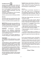
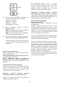
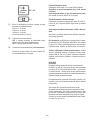
ELICA SEE YOU IX/A/90 Manualul proprietarului
- Categorie
- Hote pentru aragaz
- Tip
- Manualul proprietarului

IT Istruzioni di montaggio e d’uso
EN Installation, use and maintenance instructions
DE Montage-und Gebrauchsanweisung
FR Instructions de montage, d’utilisation et d’entretien
NL Instructies voor de montage, het gebruik en het onderhoud
ES Instrucciones de montaje, uso y mantenimiento
PT Instruções de montagem, uso e manutenção
EL Οδηγίες συναρμολόγησης, χρήσης και συντήρησης
SV Anvisningar för montering, användning och underhåll
FI Asennus-, käyttö- ja huolto-ohjeet
NO Instruksjoner for installering, bruk og vedlikehold
DA Monterings-, brugs- og vedligeholdelsesvejledning
PL Instrukcja montażu, użytkowania i konserwacji
CS Návod k montáži, použití a údržbĕ
SK Návod na montáž, používanie a údržbu
HU Szerelési utasítás, használati útmutató
BG Инструкции за монтиране, ползване и поддръжка
RO Instrucţiuni de montare, utilizare şi întreţinere
RU Руководство по монтажу, эксплуатации и обслуживанию
UK інструкції з монтажу, експлуатації та технічного обслуговування
ET Paigaldus-, kasutus- ja hooldusjuhend
LT Montavimo, naudojimo ir priežiūros instrukcijos
LV Ierīkošanas, lietošanas un tehniskās apkopes instrukcijas
SR Упутства за монтажу, употребу и одржавање
SL Navodila za montažo, uporabo in vzdrževanje
HR Upute za montažu, uporabu i održavanje
TR Montaj, kullanım ve bakım talimatları
AR
See you
-
See you

1
Fig. 2
Fig. 5 Fig. 6
Fig. 1
Fig. 3
Fig. 4

2
Fig. 7

3
Fig. 8

4
Fig. 13 Fig. 14
Fig. 9
Fig. 11 Fig. 12
Fig. 10

5
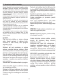
IT - Istruzioni di montaggio e d’uso
Attenersi strettamente alle istruzioni riportate in que-
sto manuale. Si declina ogni responsabilità per eventuali
inconvenienti, danni o incendi provocati all’apparecchio
derivati dall’inosservanza delle istruzioni riportate in questo
manuale. La cappa è concepita per l’aspirazione dei fumi e
vapori della cottura ed è destinata al solo uso domestico.
La cappa può avere estetiche differenti rispetto a quan-
to illustrato nei disegni di questo libretto, comunque le
istruzioni per l’uso, la manutenzione e l’installazione
rimangono le stesse.
! E’ importante conservare questo manuale per poterlo con-
sultare in ogni momento. In caso di vendita, di cessione o di
trasloco, assicurarsi che resti insieme al prodotto.
! Leggere attentamente le istruzioni: ci sono importanti infor-
mazioni sull’installazione, sull’uso e sulla sicurezza.
! Non effettuare variazioni elettriche o meccaniche sul pro-
dotto o sulle condotte di scarico.
! Prima di procedere nell’installazione dell’apparecchio
vericare che tutti i componenti non siano danneggiati. In
caso contrario contattare il rivenditore e non proseguire con
l’installazione.
Avvertenze
Prima di qualsiasi operazione di pulizia o manu-
tenzione, disinserire la cappa dalla rete elettrica
togliendo la spina o staccando l’interruttore ge-
nerale dell’abitazione.
Per tutte le operazioni di installazione e manu-
tenzione utilizzare guanti da lavoro.
L’apparecchio può essere utilizzato da bambini
di età non inferiore a 8 anni e da persone con
ridotte capacità siche, sensoriali o mentali, o
prive di esperienza o della necessaria cono-
scenza, purché sotto sorveglianza oppure dopo
che le stesse abbiano ricevuto istruzioni relative
all’uso sicuro dell’apparecchio e alla compren-
sione dei pericoli ad esso inerenti.
I bambini devono essere controllati afnché non
giochino con l’apparecchio.
La pulizia e la manutenzione non deve essere
effettuata da bambini senza sorveglianza.
Il locale deve disporre di sufciente ventilazio-
ne, quando la cappa da cucina viene utilizza-
ta contemporaneamente ad altri apparecchi a
combustione di gas o altri combustibili.
La cappa va frequentemente pulita sia inter-
namente che esternamente (ALMENO UNA
VOLTA AL MESE), rispettare comunque quanto
espressamente indicato nelle istruzioni di ma-
nutenzione riportate in questo manuale.
L’inosservanza delle norme di pulizia della cap-
pa e della sostituzione e pulizia dei ltri compor-
ta rischi di incendi.
L’impiego di amma libera è dannoso ai ltri e
può dar luogo ad incendi, pertanto deve essere
evitato in ogni caso.
La frittura deve essere fatta sotto controllo onde
evitare che l’olio surriscaldato prenda fuoco.
ATTENZIONE: Quando il piano di cottura è in
funzione le parti accessibili della cappa posso-
no diventare calde.
Attenzione! Non collegare l’apparecchio alla
rete elettrica nche l’installazione non è total-
mente completata.
Per quanto riguarda le misure tecniche e di
sicurezza da adottare per lo scarico dei fumi
attenersi strettamente a quanto previsto dai re-
golamenti delle autorità locali competenti.
L’aria aspirata non deve essere convogliata in
un condotto usato per lo scarico dei fumi pro-
dotti da apparecchi a combustione di gas o di
altri combustibili.
Mai utilizzare la cappa senza griglia corretta-
mente montata!
La cappa non va MAI utilizzata come piano di
appoggio a meno che non sia espressamente
indicato.
Utilizzare solo le viti di ssaggio in dotazione
con il prodotto per l’installazione o, se non in
dotazione, acquistare il tipo di viti corretto. Uti-
lizzare la lunghezza corretta per le viti che sono
identicati nella Guida all’installazione. In caso
di dubbio, consultare il centro di assistenza au-
torizzato o personale qualicato similare.

6
ATTENZIONE! La mancata installazione di viti
e dispositivi di ssaggio in conformità di queste
istruzioni può comportare rischi di natura elet-
trica.
Si declina ogni responsabilità per eventuali in-
convenienti, danni o incendi provocati all’appa-
recchio derivati dall’inosservanza delle istruzio-
ni riportate in questo manuale.
Nell’intento costante di migliorare i nostri pro-
dotti, ci riserviamo il diritto di apportare alle loro
caratteristiche tecniche, funzionali o estetiche
tutte le modiche derivanti dalla loro evoluzio-
ne. Nel caso di versione con motore esterno,
per il normale funzionamento della cappa è ne-
cessario utilizzare un gruppo aspirante (motore
esterno) della stessa casa produttrice.
Questo apparecchio è contrassegnato in con-
formità alla Direttiva Europea 2012/19/EC,
Waste Electrical and Electronic Equipment
(WEEE). Assicurandosi che questo prodotto sia
smaltito in modo corretto, l’utente contribuisce
a prevenire le potenziali conseguenze negative
per l’ambiente e la salute.
Il simbolo sul prodotto o sulla documen-
tazione di accompagnamento indica che questo
prodotto non deve essere trattato come riuto
domestico ma deve essere consegnato pres-
so l’idoneo punto di raccolta per il riciclaggio
di apparecchiature elettriche ed elettroniche.
Disfarsene seguendo le normative locali per lo
smaltimento dei riuti. Per ulteriori informazioni
sul trattamento, recupero e riciclaggio di questo
prodotto, contattare l’idoneo ufcio locale, il ser-
vizio di raccolta dei riuti domestici o il negozio
presso il quale il prodotto è stato acquistato.
Apparecchiatura progettata, testata e realizzata
nel rispetto delle norme sulla:
• Sicurezza: CEI/EN 60335-1; CEI/EN 60335-2-
31, CEI/EN 62233.
• Prestazione: CEI/EN 61591; ISO 5167-1; ISO
5167-3; ISO 5168; CEI/EN 60704-1; CEI/EN
60704-2-13; ISO 3741; EN 50564; CEI 62301.
• EMC: EN 55014-1; CISPR 14-1; EN 55014-2;
CISPR 14-2; CEI/EN 61000-3-2; CEI/EN 61000-
3-3. Suggerimenti per un corretto utilizzo al ne
di ridurre l’impatto ambientale: Quando iniziate
a cucinare, accendere la cappa alla velocità mi-
nima, lasciandola accesa per alcuni minuti an-
che dopo il termine della cottura. Aumentare la
velocità solo in caso di grandi quantità di fumo
e vapore, utilizzando la funzione booster solo in
casi estremi. Per mantenere ben efciente il si-
stema di riduzione degli odori, sostituire, quan-
do è necessario, il/i ltro/i carbone. Per mante-
nere ben efciente il ltro del grasso, pulirlo in
caso di necessità. Per ottimizzare l’efcienza e
minimizzare i rumori, utilizzare il diametro mas-
simo del sistema di canalizzazione indicato in
questo manuale.
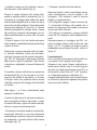
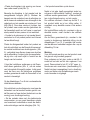
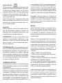
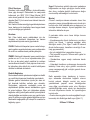
Utilizzazione
La cappa è realizzata per essere utilizzata in
versione aspirante ad evacuazione esterna o
ltrante a ricircolo interno.
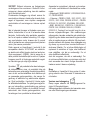
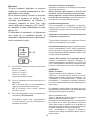
Versione aspirante
I vapori vengono evacuati verso l’esterno tra-
mite un tubo di scarico ssato alla angia di
raccordo.
Il diametro del tubo di scarico deve essere equi-
valente al diametro dell’anello di connessione.

7
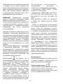
Versione ltrante
L’aria aspirata verrà sgrassata prima di essere
riconvogliata nella stanza. Per utilizzare la cap-
pa in questa versione è necessario comprare
un KIT di Installazione ltrante SEE YOU che,
oltre a contenere i ltri carbone long life (Fig.
13), contiene una serie di tubazioni che convo-
gliano l’aria nella parte frontale.
Nota: L’aria riciclata attraverso i ltri carbone
viene rinviata nella cucina attraverso un con-
dotto che convoglia l’aria su un lato del mobile.
Installazione
Nota: l’installazione deve essere eseguita in
modo che sia sempre garantita l’accessibilità
della cappa e dei componenti elettronici per
eventuali interventi in assistenza tecnica.
ATTENZIONE: Questo apparecchio non è stato
concepito per i fornelli a gas.
RACCOMANDAZIONE: Vi raccomandiamo di
installare la scatola metallica contenente i com-
ponenti elettronici almeno a 10 cm dal suolo e
ad una distanza sufciente da tutte le fonti di
calore (es: lato di un forno, o piano cottura).
Se le istruzioni di installazione del dispositivo di
cottura a gas specicano una distanza maggio-
re, bisogna tenerne conto.
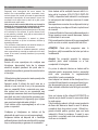
Collegamento Elettrico
L’allacciamento della cappa alla rete elettrica deve
essere effettuato da personale tecnico qualicato
e specializzato. La tensione di rete deve corrispon-
dere alla tensione riportata sull’etichetta caratteri-
stiche situata all’interno della cappa. Se provvista
di spina allacciare la cappa ad una presa confor-
me alle norme vigenti posta in zona accessibile
anche dopo l’installazione. Se sprovvista di spina
(collegamento diretto alla rete) o la spina non è
posta in zona accessibile, anche dopo installazio-
ne, applicare un interruttore bipolare a norma che
assicuri la disconnessione completa della rete nel-
le condizioni della categoria di sovratensione III,
conformemente alle regole di installazione.
Attenzione! Prima di ricollegare il circuito della
cappa all’alimentazione di rete e di vericarne il
corretto funzionamento, controllare sempre che
il cavo di rete sia stato montato correttamente.
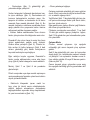
Montaggio
Prima di procedere nell’installazione dell’ap-
parecchio vericare che tutti i componenti non
siano danneggiati, in caso contrario contattare il
rivenditore e non proseguire con l’installazione.
Inoltre leggere attentamente tutte le istruzioni di
seguito riportate.
Utilizzare un tubo di evacuazione aria che abbia
la lunghezza massima non superiore a 5 metri.
• Limitare il numero di curve nella canalizzazio-
ne poiché ogni curva riduce l’efcienza di aspi-
razione equiparata a 1 metro lineare. (Es: se si
utilizzano n°2 curve a 90°, la lunghezza della
canalizzazione non dovrebbe superare i 3 metri
di lunghezza).
• Evitare cambiamenti drastici di direzione.
• Utilizzare un condotto con diametro da 150mm
costante per tutta la lunghezza.
• Utilizzare un condotto di materiale approvato
normativamente.
• Per il mancato rispetto delle precedenti istru-
zioni la ditta fornitrice non risponderà per pro-
blemi di portata o rumorosità e nessuna garan-
zia sarà prestata.
Prima di effettuare il foro controllare che nella
parte interna del mobile, in corrispondenza del-
la zona di alloggio della cappa, non sia presente
la struttura del mobile o altri particolari che po-
trebbero creare problemi per la corretta installa-
zione. Vericare che gli ingombri della cappa e
del piano cottura siano compatibili con il mobile
e quindi sia fattibile l’installazione.
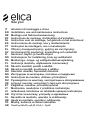
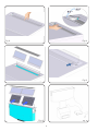
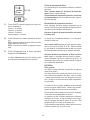
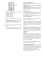
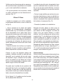
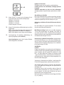
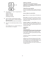
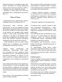
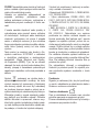
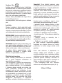
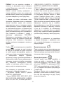
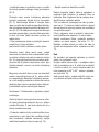
• Effettuare nella parte posteriore del piano
cottura, un foro rettangolare con le seguenti di-
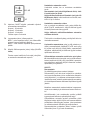
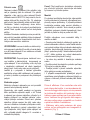
mensioni: (Fig. 1).
832mm X 102mm.

8
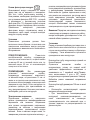
• Installare la cappa nel foro praticato, inseren-
dolo da sopra, come indicato (Fig. 2).
Fissare la cappa all’interno del mobile utiliz-
zando le apposite staffe in dotazione (Fig. 3).
Procedere al montaggio delle staffe nella parte
inferiore della cappa facendo in modo che tra la
parte inferiore della staffa ed il fondo del mobile
rimanga una distanza di 2 mm (Fig. 4). Questa
distanza permetterà la trazione verso il basso
del prodotto al momento del ssaggio, per far
aderire perfettamente la cornice inox sul piano
di lavoro.
• Prima di inserire le viti nel mobile assicurarsi
che il prodotto sia perfettamente perpendicolare
al piano di lavoro.
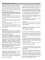
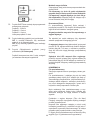
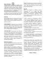
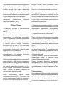
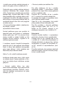
Posizionare il gruppo aspirante sotto al prodot-
to, facendo coincidere l’uscita aria del down-
draft con l’ingresso aria del motore di aspirazio-
ne.( FIG. 5); collegare le due ange (indicare
dalle frecce in gura 5) mediante il tubo fornito
in dotazione, tagliandolo in base all’altezza del
mobile.
E’ possibile usufruire dell’uscita aria posteriore
del downdraft (g. 6), solo nel caso in cui le di-
mensioni del mobile lo permettano, in tal caso
la angia uscita aria posteriore dovrà essere
installata a seguito del ssaggio del downdraft
nel mobile.
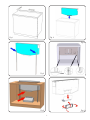
Nelle gure 7 e 8 sono schematizzati degli
esempi di installazione.
L’uscita aria del motore di aspirazione deve es-
sere convogliato all’esterno del mobile, in caso
di versione ltrante, oppure all’esterno dell’abi-
tazione in caso di versione aspirante.
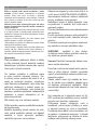
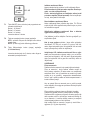
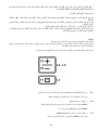
• Posizionare la scatola metallica contenente i
componenti elettronici in una zona facilmente
accessibile per eventuali interventi di assisten-
za collegando i connettori elettrici della stessa
alla cappa. (g. 14).
• Collegare il prodotto alla rete elettrica
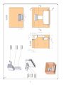
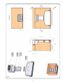
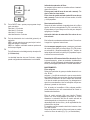
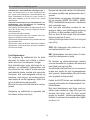
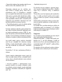
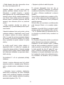
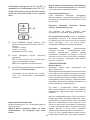
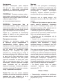
Dopo aver aperto il vetro come indicato nel ca-
pitolo funzionamento, occorre installare i ltri
antigrasso, i ltri carbone in caso di versione
ltrante e la griglia estetica.
I ltri antigrasso vengono inseriti come da g.
11, collocandoli all’interno del prodotto no a
quanto non raggiungo la loro sede, la rimozione
avviene nel verso contrario.
I ltri carbone, se necessari, vengono installati
prima dei ltri antigrasso nella medesima ma-
niera.
Successivamente al montaggio dei ltri, col-
locare la griglia estetica nella relativa se, vedi
gura 11 e 12. La griglia può essere rimossa
prendendola per gli appositi pomelli, indicati in
gura 12.
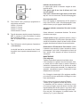
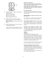
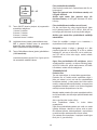
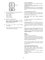
Funzionamento
Per un normale funzionamento del prodotto oc-
corre aprire il vetro agendo come segue.
Spingere il vetro verso il basso, nella parte an-
teriore come indicato in g. 9, si avrà lo sgancio
del vetro e la relativa apertura per circa 2Cm, si
dovrà quindi ruotarlo no a 45° o 90° di apertu-
ra, in base alle esigenze. (vedi gura 10).
A seguito dell’apertura del vetro si potrà aziona-
re il motore di aspirazione agendo sulla pulsan-
tiera come sotto indicato.

9
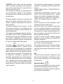
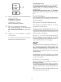
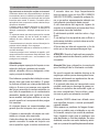
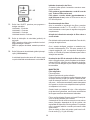
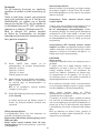
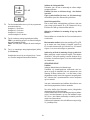
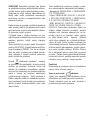
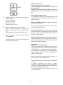
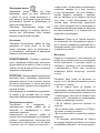
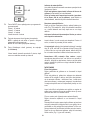
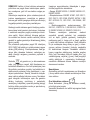
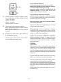
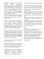
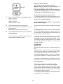
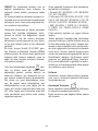
Indicatore di saturazione ltri
La cappa indica quando e necessario eseguire la manu-
tenzione dei ltri:
Filtro grassi (ogni 40 ore circa di utilizzo): tutti i Led
con luce azzurra.
Filtro odori a carbone attivo (ogni 160 ore circa di utiliz-
zo): tutti i Led con luce azzurra, il led L2 e L3 lampeggiano.
Reset saturazione ltri
Dopo aver eseguito la manutenzione dei ltri premere a
lungo il tasto T1 e T3, i led L1, L2 e L3 lampeggiano breve-
mente in azzurro per poi spegnersi denitivamente.
Attivazione indicatore saturazione ltro odori a carbo-
ne attivo.
Questo indicatore è normalmente disattivato. Per attivarlo
procedere come segue:
A cappa spenta premere e mantenere premuto a lungo e
contemporaneamente T1 e T2: prima si accende L1 poi an-
che L2 e L3 dopodichè al rilascio dei tasti i led L2 e L3 lam-
peggiano brevemente ad indicare l’avvenuta attivazione.
Disattivazione LED saturazione ltro carbone: ripetere
l’operazione sopra descritta, prima si accendono contem-
poraneamente i led L1, L2 e L3 dopodichè al rilascio dei
tasti i led L2 e L3 si spengono ad indicare l’avvenuta di-
sattivazione.
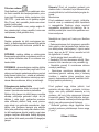
MANUTENZIONE
Filtro antigrasso
Trattiene le particelle di grasso derivanti dalla cottura.
Il ltro antigrasso e la griglia di raccolta sottostante, devo-
no essere puliti una volta al mese (o quando il sistema di
indicazione di saturazione dei ltri se previsto sul modello
in possesso indica questa necessità), con detergenti non
aggressivi, manualmente oppure in lavastoviglie a basse
temperature ed a ciclo breve.
Con il lavaggio in lavastoviglie il ltro antigrasso metallico
può scolorirsi ma le sue caratteristiche di ltraggio non cam-
biano assolutamente.
Filtro ai carboni attivi (Solo per Versione Filtrante).
Trattiene gli odori sgradevoli derivanti dalla cottura.
La saturazione del ltro carbone si verica dopo un uso
più o meno prolungato a seconda del tipo di cucina e della
regolarità della pulizia del ltro grassi. In ogni caso è neces-
sario sostituire la cartuccia al massimo ogni quattro mesi.
Dopo aver tolto i ltri antigrasso, è possibile inserire i ltri
carbone (Fig. 13) (non in dotazione).
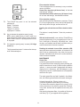
T1.
T2.
T3.
Tasto ON/OFF timer: premere per programmare lo
spegnimento automatico:
Velocità 1: 20 minuti
Velocità 2: 15 minuti
Velocità 3: 10 minuti
Velocità intensiva: 5 minuti
Tasto di decremento velocità (potenza) di aspirazione
OFF 1: premere più volte per diminuire la velocita
no a spegnere la cappa.
OFF 2: a qualsiasi velocità mantenere premuto a
lungo.
Tasto ON/aumento velocità (potenza) di aspirazione
(1-2-3-Intensivo).
La velocità intensiva ha una durata di circa 5 minuti,
dopodichè viene impostata automaticamente la ve-
locità 2.

10
EN – Installation and use instructions
Strictly follow all the instructions given in this manual.
The manufacturer declines all responsibility for any incon-
venience, damages or re caused by the appliance due
to failure to comply with the instructions mentioned in this
manual. The hood was designed to suction cooking fumes
and vapours, therefore it is intended for household use only.
The aesthetic features of the hood might be different
from the ones shown in the drawings of this manual; in
any case, the use, installation and maintenance instruc-
tions are the same.
! Please keep this manual for future reference. Should the
appliance be sold or passed on to others, make sure that
these instructions are passed on with it.
! Carefully read these instructions, where important informa-
tion on the appliance installation, use and safety is provided.
! Do not perform any electrical or mechanical modications
on the appliance or on the exhaust ducts.
! Before carrying out installation, make sure that all compo-
nents are not damaged. Please contact your retailer in case
they are damaged, and do not proceed with the installation.
WARNINGS
Before carrying out any maintenance or clea-
ning operations, disconnect the hood from the
power supply, by unplugging it from the mains
supply or by switching off the main switch.
Wear protective gloves during any installation
and maintenance operation.
The appliance is not intended for use by chil-
dren under 8, and by persons with reduced
physical, sensory or mental capabilities, or lack
of experience and knowledge, unless they have
been given supervision or instructions concer-
ning the safe use of the appliance and the risk
connected to it by a person responsible for their
safety.
Children should be supervised to ensure that
they do not play with the appliance.
Cleaning and maintenance operations shall not
be performed by children without supervision.
Adequately ventilate the room when the cooker
hood and other appliances, powered by energy
other than electricity, such as gas combustion
or other fuels, are used simultaneously.
The hood shall be cleaned regularly, both in-
ternally and externally (AT LEAST ONCE A
MONTH ); please follow the instructions given
in the maintenance section of this manual.
Failure to comply with the instructions provided
for the hood cleaning operations, as well as l-
ter cleaning and replacement operations, may
result in re risk.
Open ames can damage the grease lters and
can cause re risk, therefore cooking over open
ames should be strictly avoided.
Deep frying should be done under constant su-
pervision, in order to keep overheated oil from
igniting.
CAUTION: When the hob is in use, the accessi-
ble parts of the hood may become hot.
Caution! Do not connect the appliance to the
power source until installation is completed.
As far as the technical and safety measures, to
be implemented to discharge fumes, are con-
cerned, strictly comply with provisions set forth
in relevant regulations by the local competent
authorities.
Air extracted shall not be conveyed into a duct
used to discharge fumes coming from applian-
ces fed by gas combustion or other fuels.
Never use the hood without having the grid pro-
perly installed!
NEVER use the hood as a support surface
unless it is expressly mentioned in the instruc-
tions. Only use the xing screws supplied with
the appliance during installation.
In case they are not supplied, please buy a su-
itable screw type. Use proper length screws,
specic details are given in the Installation Gui-
de. In case of doubts, please contact our au-
thorized technical assistance center or similarly
qualied personnel.

11
CAUTION! Fixing screws and xing devices
shall be installed according to the instructions
given in this manual; failure to comply with them
might result in electric risk .
The manufacturer declines all responsibility for
any inconvenience, damage or re caused by
the appliance, due to failure to comply with the-
se instructions.
Constantly seeking to improve our products, we
reserve the right to modify their technical, fun-
ctional, or aesthetic characteristics as a result of
their upgrading.
In the case of external motor version , for the
hood normal operation, it is necessary to use
a suctioning unit (external motor) made by the
same manufacturer.
This appliance is marked according to the Euro-
pean directive 2012/19/EC on Waste Electrical
and Electronic Equipment (WEEE By ensuring
this product is disposed of correctly, you will
help prevent potential negative consequences
for the environment and human health.
The symbol on the product or on the do-
cumentation included with it, means that this
product shall not be disposed of as household
waste. Instead it shall be handed over to the su-
itable collection point for the recycling of electri-
cal and electronic equipment. The product shall
be disposed of according to applicable local
standards and regulations on waste disposal.
For more detailed information on the disposal
and recycling of this product, please contact
your local city ofce, your household waste di-
sposal service or the shop where you purcha-
sed the product.
This appliance has been designed , tested and
produced in compliance with all relevant stan-
dards on :
• Safety: CEI/EN 60335-1; CEI/EN 60335-2-31,
CEI/EN 62233.
• Performance: CEI/EN 61591; ISO 5167-1; ISO
5167-3; ISO 5168; CEI/EN 60704-1; CEI/EN
60704-2-13; ISO 3741; EN 50564; CEI 62301.
• EMC: EN 55014-1; CISPR 14-1; EN 55014-2;
CISPR 14-2; CEI/EN 61000-3-2; CEI/EN
61000-3-3.
Tips for the proper use of the appliance, aimed
at reducing environmental impact.
Switch the hood on at minimum speed when
you start cooking and leave it in operation for
some minutes after you nish cooking. Increase
the speed only in case of high quantities of fu-
mes and vapours, using the boost feature only
when absolutely necessary.
In order to keep the odour reducing system
efcient over time, replace the charcoal lter/s
whenever necessary.
In order to keep the grease lter efcient over
time, clean it whenever necessary.
Use a piping system with the maximum diame-
ter specied in this manual, in order to reach
very high performances and maintain low noise
levels.
Use
The hood can be used both in aspiration mode
with external discharge of suctioned air, and in
ltering mode, where the air is recycled back
into the room.
Aspiration Mode
Vapours are discharged to the outside, through
the specic exhaust pipe xed to the ange.
The exhaust pipe diameter shall be the same as
the connection ring diameter.

12
Filtering Mode
The air that is sucked in will be ‘degreased’ befo-
re being re-conveyed into the room. You need to
buy the specic SEE YOU Filtering version KIT, if
you wish to use the hood in this mode.
The kit will include: long life charcoal lters (Fig.
13), and some pipes for conveying the air to the
front side of the hood.
Note: The air recycled through the charcoal lters
is conveyed back into the kitchen through a duct
that conveys the air along a side of the cabinet.
Installation
Note: installation shall be performed in such a
way as to allow that the hood and its electric
components can be easily accessible in case of
technical assistance.
WARNING: Place the metal box containing the
electronic components at a minimum distance
of 65 cm from the gas hob or anyway at 65 cm
from the hood aspiration area.
RECOMMENDATION: we advise that you in-
stall the metal box, containing the electronic
components, at 10 cm from the oor, at least,
and at a safe distance from any heat source
(e.g.: an oven side, or a hob ).
In the case that the installation instructions of
your gas cooker mention a higher distance, ple-
ase comply with this requirement.
Electrical Connection
The connection of the hood to the power supply
shall be performed by qualied and specialised
technical personnel.
The mains voltage shall correspond to the vol-
tage value specied on the rating label found in-
side the hood. If the appliance is equipped with
a plug, the hood shall be connected to a socket
which is compliant to the relevant standards in
force, and which is located in an easily reacha-
ble area, also after installation. If the appliance
is not equipped with a plug (direct connection
to power supply), or if the plug is not found in
an easily reachable place after installation, use
an approved double-pole main switch, ensuring
complete disconnection from the power supply
at the overvoltage category III conditions, in ac-
cordance with the installation procedure.
Caution! Before reconnecting the hood elec-
tric circuit to the power supply, and to check for
proper operation, please always make sure the
mains lead has been installed properly.
Installation
Before carrying out the appliance installation,
please check that all components are not dama-
ged, in such a case contact your retailer and do
not proceed with any further installation step. In
addition, carefully read all the instructions spe-
cied below.
Use an air exhaust pipe whose maximum length
does not exceed 5 meters .
.• Limit the number of elbows in the piping, since
each elbow reduces the air
capacity of 1 linear meter. (Ex. : if you use no.
2 x 90 ° elbows, the length of piping should not
exceed 3 meters)
•Avoid abrupt direction changes.
• Use a 150 mm constant diameter pipe for the
whole length
• Use piping approved by relevant standards in
force.
• The manufacturer shall not be deemed respon-
sible for air capacity or noise problems caused by
failure to comply with the above instructions and
no warranty on the product shall be provided.
Before making the hole, check that there are
no structural, or other parts inside the cabinet,
where the appliance is to be placed, which
could hinder proper installation. Check that the
dimensions of the hood and the ones of the hob
are compatible with the cabinet, so that the in-
stallation can be carried out properly.
• Make a rectangular hole in the rear side of the
cook top, of the following sizes: (Fig. 1).
832mm X 102mm.

13
• Fit the hood into the hole made, by inserting it
from above , as shown in (Fig. 2).
Secure the hood inside the cabinet, by using the
specic xing brackets provided (Fig.3). Fix the
brackets into the lower side of the hood in such
a way that there is a 2 meter distance between
the bracket lower side and the bottom of the
cabinet mm (Fig.4). This distance will allow to
pull the hood downwards during installation, in
order to make the stainless steel frame perfectly
adhere with the worktop.
Before inserting the screws into the cabinet,
make sure that the appliance is perfectly per-
pendicular with the worktop.
Place the suction unit under the appliance, by
making the downdraft air- outlet coincide with
the motor air-inlet.( FIG. 5 ); connect the two
anges (indicated by the arrows in gure 5) by
means of the pipe supplied with the appliance,
and cut it accordingly to the cabinet height .
The downdraft rear air-outlet (g. 6 ) can be
used only if the cabinet size allows you to do
so; in such a case the rear air-outlet ange
shall be installed after the downdraft has been
installed into the cabinet.
Some examples of installations are given in Fi-
gure 7 and 8
The motor air out-let shall be directed toward
the outside of the cabinet if the appliance is
used in the ltering version, or to the outside of
the house if the appliance is used in the aspira-
tion version.
• Place the metal box containing the electronic
components in an easily reachable area for
possible technical assistance operations, by
connecting the electric connectors of the box to
the hood (g. 14).
• Connect the appliance to the power supply
After opening the glass, as specied in the ‘how
the hood works ‘ section of this manual, you
need to t the grease lters and the charcoal
lters, in case the hood is used in ltering mode,
as well as the aesthetic grid.
Grease lters are mounted as shown in g.11,
placing them inside the appliance until they re-
ach their seat; to remove them, please carry out
the reverse procedure.
Charcoal lters, if necessary, are t before
mounting the grease lters, by following the
same procedure.
After mounting the lters, the aesthetic grid
shall be t into the related housing, see gure
11 and 12. The grid is removed by grabbing it by
the specic knobs shown in gure 12.
How the hood works
In order to operate the appliance, it is necessary
to open the glass by following this procedure:
Push the glass downwards in the front side, as
shown in g. 9; the glass will be released and
will open of about 2 cm,: then the glass shall be
rotated up to a 45° or 90° opening , based on
your needs. (see gure 10).
Following the glass opening, it will be possible
to operate the suction motor by using the push-
button panel as follows:

14
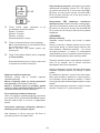
Filter saturation indicator
The hood displays when it is necessary to carry out mainte-
nance on the lters:
Grease lter (about every 40 hours of use): all the Leds
with blue light will ash
Activated charcoal lter (about every 160 hours of use):
all the Leds with blue light, leds L2 and L3 will ash.
Filter saturation resetting
After performing the lter maintenance, press keys T1 and
T3, for a prolonged period of time, Leds L1, L2 and L3 will
ash shortly with a blue light, and then will turn off.
Enabling the activated charcoal lter saturation indica-
tor.
This indicator is usually disabled. Follow this procedure to
enable it:
With the hood turned off, press and keep T1 and T2 keys
pressed simultaneously for a prolonged period of time: at
rst L1 will light up, followed by L2 and L3; then, when
the keys are released, leds L2 and L3 will ash shortly to
conrm that activation has been completed.
Disabling the activated charcoal lter saturation LED:
repeat the above mentioned procedure; at rst leds L1, L2
and L3 light up simultaneously; then, when the keys are
released, leds L2 and L3 will turn off to conrm that deac-
tivation has been completed.
MAINTENANCE
Grease lter
It captures grease particles deriving from cooking.
The grease lter and the underlying grease collecting grid,
shall be cleaned once a month (or when the lter saturation
indicator - in case your model is equipped with this feature-
displays that it is necessary), with mild detergent, by wa-
shing them by hand or in the dishwasher at low temperature
and with a short cycle.
The metal grease lter may fade if washed in the dishwa-
sher, but its ltering characteristics will remain unchanged.
Activated charcoal lter (Filtering Version only )
It captures unpleasant odours deriving from cooking.
The charcoal lter saturation depends on the usage, on the
cooking style and on how often the grease lter is cleaned.
In any case, the lter shall be replaced at least every four
months.
After removing the grease lters, it is possible to t the char-
coal lters (Fig. 13) (not supplied with the appliance).
T1.
T2.
T3.
Timer ON/OFF key: press it to set the automatic
switching off:
Speed 1: 20 minutes
Speed 2: 15 minutes
Speed 3: 10 minutes
High Speed : 5 minutes
Key to decrease the aspiration speed ( power)
OFF 1: press it multiple times, in order in order to re-
duce the aspiration speed until the hood is turned off.
OFF 2: hold it down for a prolonged period of time,
at any speed.
ON /aspiration speed (power) increase (1-2-3-High
speed) key.
The High speed lasts about 5 minutes: after that spe-
ed 2 is automatically set .

15
DE - Montage - und Gebrauchsanweisung
Die Instruktionen, die in diesem Handbuch gegeben
werden, müssen strikt eingehalten werden. Es wird kei-
nerlei Haftung übernommen für mögliche Mängel, Schäden
oder Brände des Geräts, die auf die Nichtbeachtung der
Vorschriften in diesem Handbuch zurückzuführen sind. Die
Dunstabzugshaube ist für den häuslichen Gebrauch und
nur zum Abzug und Reinigung von Kochdämpfen aus der
Zubereitung von Lebensmitteln bestimmt.
Das Gerät kann von der ästhetischen Seite her anders
sein als die Zeichnungen, die in dieser Gebrauchsan-
weisung dargestellt sind. Die Bedienungsanleitung, die
Wartung und die Installation sind aber einbehalten.
! Bewahren Sie diese Anleitung für zukünftiges Nachschla-
gen auf und geben Sie diese Anleitung mit dem Gerät wei-
ter, falls dieses an einer anderen Person weitergegeben
wird.
! Diese Bedienungsanleitung gründlich lesen. Sie enthält
wichtige Informationen zu Sicherheit, Installation, Betrieb.
! Nehmen Sie keine mechanischen oder elektrischen Ände-
rungen am Geräten oder am Abluftkanal vor.
! Vor der Installation vergewissern Sie sich, dass das Gerät
keine Transportschäden aufweist. Bei auftretenden Proble-
men setzen Sie sich bitte mit Ihrem Händler in Verbindung
und die Montage nicht fortsetzen.
Warnung
Trennen Sie die Dunstabzugshaube immer
vom Stromnetz über den Hauptschalter, bevor
Sie die Reinigung oder Wartungsarbeiten vor-
nehmen.
Alle Installation- und Wartungsarbeiten mit
Schutzhandschuhe vornehmen.
Dieses Gerät darf nicht von Personen (ein-
schließlich Kindern unter 8 Jahren) mit einge-
schränkten physischen, sensorischen oder gei-
stigen Fähigkeiten sowie von Personen bedient
werden, denen es an Erfahrung und notwendi-
gem Wissen fehlt, sofern diese Personen nicht
von einer verantwortlichen Person beaufsichtigt
und nachhaltig hinsichtlich der Bedienung des
Geräts unterwiesen wurden.
Kinder sollten grundsätzlich beaufsichtigt wer-
den, damit sie nicht mit dem Gerät spielen.
Kinder dürfen die Dunstabzugshaube nicht
ohne Aufsicht reinigen oder warten.
Der Raum muss über eine hinreichende Belüf-
tung verfügen, wenn die Dunstabzugshaube
mit anderen gas- oder brennstoffbetriebenen
Geräten gleichzeitig verwendet wird.
Die Haube muss regelmäßig innen und außen
gereinigt werden (MINDESTENS EINMAL IM
MONAT), diesbezüglich sind in jedem Fall die
ausdrücklichen Angaben in der Wartungsanlei-
tung dieses Handbuchs zu beachten.
Die Nichtbeachtung dieser Anweisungen zur
Reinigung des Gerätes und zum Wechsel bzw.
zur Reinigung der Filter kann zum Brand führen.
Flambieren Sie nie unter der Dunstabzugshau-
be.
Die Flammen können die Fettlter einer Dun-
stabzugshaube in Brand setzen. Nicht auf offe-
ner Flamme kochen!
Das Frittieren muss unter Aufsicht erfolgen, um
zu vermeiden, dass das überhitzte Öl Feuer
fängt.
ACHTUNG: Während des Betriebs des Koch-
felds können die erreichbaren Teile der Dun-
stabzugshaube heiß werden.
Achtung! Das Gerät nicht an das Stromnetz
anschließen, solange die Installation noch nicht
abgeschlossen ist.
In Bezug auf technische und Sicherheitsmaß-
nahmen für die Ableitung der Abluft sind die
Vorschriften der zuständigen örtlichen Behör-
den strengstens einzuhalten.
Die abzugebende Luft darf nicht in eine Abluft-
leitung geführt werden, die für den Abzug von
Rauch oder anderen Gas- und Brennstoff-
geräten benutzt werden.
Die Dunstabzugshaube niemals ohne korrekt
montiertes Gitter in Betrieb setzen!
Die Dunstabzugshaube darf NIEMALS als Ab-
stelläche verwendet werden, sofern dies nicht
ausdrücklich angegeben wird.

16
Für die Montage verwenden Sie nur die mi-
tgelieferten Schrauben oder, falls die nicht im
Lieferumfang enthalten sind, besorgen Sie sich
geeignete Schrauben. Die in der Montageanlei-
tung angegebene Schraubenlänge einhalten.
Im Zweifel, den Kundendienst oder einen Fa-
chpersonal fragen.
ACHTUNG! Die Nichtverwendung von Schrau-
ben und Befestigungsteilen gemäß den vorlie-
genden Anleitungen kann elektrische Gefahr
verursachen.
Der Hersteller übernimmt keine Haftung für
irgendwelche Schäden oder Brandschäden
am Gerät, die auf eine Nichteinhaltung der Si-
cherheitsvorschriften zurückzuführen sind.
Wir behalten uns weiter das Recht vor techni-
sche, funktionelle und ästhetische Verbesse-
rungen und durch Weiterentwicklung bedingte
Änderungen am Produkt vorzunehmen.
Für den normalen Betrieb des Modells mit Au-
ßenmotor ist ein Absaugaggregat (Außenmo-
tor) derselben Firma zu verwenden.
Dieses Elektrohaushaltsgerät ist entsprechend
der EU-Richtlinie 2012/19/EC über Elektro- und
Elektronik – Altgeräte (WEEE) gekennzeichnet.
Durch Ihren Beitrag zum korrekten Entsorgen
dieses Produkts schützen Sie die Umwelt und
die Gesundheit Ihrer Mitmenschen.
Das Symbol auf dem Produkt oder sei-
ner Verpackung weist darauf hin, dass dieses
Produkt nicht als normaler Haushaltsabfall zu
behandeln ist, sondern an einem Sammelpunkt
für das Recycling von elektrischen und elektro-
nischen Geräten abgegeben werden muss.
Umwelt und Gesundheit werden durch falsches
Entsorgen gefährdet. Weitere Informationen
über das Recycling dieses Produkts erhalten
Sie von Ihrem Rathaus, Ihrer Müllabfuhr oder
dem Geschäft, in dem Sie das Produkt gekauft
haben.
Das Gerät wurde gemäß den folgenden Richtli-
nien entwickelt, getestet und hergestellt:
• Sicherheit: CEI/EN 60335-1; CEI/EN 60335-2-
31, CEI/EN 62233.
• Leistung: CEI/EN 61591; ISO 5167-1; ISO
5167-3; ISO 5168; CEI/EN 60704-1; CEI/EN
60704-2-13; ISO 3741; EN 50564; CEI 62301.
• EMC: EN 55014-1; CISPR 14-1; EN 55014-
2; CISPR 14-2; CEI/EN 61000-3-2; CEI/EN
61000-3-3.
Tipps für eine richtige Verwendung zur Erhal-
tung unserer Umwelt: die Dunstabzugshaube
bei Kochbeginn auf Minimum einschalten und
wenige Minuten auch nach Kochende laufen
lassen. Die Leistung nur mit zunehmender
Dampf- oder Geruchsbildung erhöhen und die
Booster-Funktion nur in extremen Fällen ein-
schalten. Eine regelmäßige Reinigung der Ko-
hlelter garantiert auf Dauer eine gute Sauglei-
stung. Den Fettlter bei Bedarf reinigen. Um die
Leistung zu erhöhen und das Betriebsgeräusch
zu reduzieren, ein Abluftrohr mit dem in der
Gebrauchsanleitung angegebenen maximalen
Durchmesser verwenden.
Betriebsart
Diese Dunstabzugshaube ist weder für den
Abluft weder für den Umluft geeignet.
Abluftbetrieb
Die Dämpfe werden mittels eines an den Flansch
befestigten Abluftrohrs ins Freie geleitet.
Der Diameter des Abluftrohrs muss mit dem
Diameter des Flanschs übereinstimmen.

17
Umluftbetrieb
Die abgesaugte Luft wird gereinigt und im
Raum wieder zurückgeleitet. Für diese Dun-
stabzugshaube muss ein Kohleltersystem-Kit
SEE YOU installiert werden, der Long Life-Ko-
hlelter (Abb. 13) sowie mehrere Röhre enthält,
um die Luft aus der Vorderseite zu leiten.
Hinweis: Die durch die Kohlelter gereinigte
Luft wird in die Küche mittels eines Rohrs an
der Möbelseite zurückgeleitet.
Montage
Hinweis: Die Montage muss so durchgeführt
werden, dass die Dunstabzugshaube und die
elektrischen Bauelementen für eventuelle War-
tungseingriffe leicht erreichbar sind.
ACHTUNG: Der Mindestabstand zwischen dem
Metall-Elektrokasten mit den elektronischen
Bauelementen und der Gas-Kochplatte, sowie
der Dunstabzugshaube, muss 65 cm betragen.
HINWEIS: Der Mindestabstand zwischen dem
Metall-Elektrokasten mit den elektronischen
Bauelementen und dem Boden muss 10 cm
betragen, ein ausreichender Abstand zu Wär-
mequellen (z.B. Ofenseite oder Kochplatte).
Gibt die Montageanleitung der Gas-Kochplatte
einen höheren Abstand an, muss dieser berück-
sichtigt werden.
Elektrischer Anschluss
Der elektrische Anschluss der Dunstabzugshaube
muss von Fachpersonal durchgeführt werden.
Die Netzspannung muss der Spannung entspre-
chen, die auf dem Betriebsdatenschild im Innern
der Haube angegeben ist. Ist das Gerät mit einem
Stecker ausgestattet, muss die Steckdose leicht
zugänglich sein und mit den Richtlinien überein-
stimmen. Sollte das Gerät nicht über einen Ste-
cker verfügen (direkter Anschluss am Stromnetz)
oder dieser nach der Installation schlecht zugän-
glich sein, muss ein normgerechter zweipoliger
Schalter zum Abtrennen des Geräts vom Strom-
netz vorgesehen werden, entsprechend den Be-
dingungen der Überspannungskategorie III.
Achtung! Vor der Inbetriebnahme der Dunstab-
zugshaube muss sichergestellt sein, dass die
Netzversorgung (Steckdose) ordnungsgemäß
montiert wurde.
Montage
Vor dem Einbau des Geräts vergewissern Sie
sich, dass alle Bestandteile nicht beschädigt
sind. Andersfalls, bitte den Verkäufer kontaktie-
ren und den Einbau abbrechen.
Bitte alle folgenden Anweisungen sorgfältig le-
sen.
Ein Abluftrohr verwenden, das nicht länger als
5 Meter ist.
• Die Zahl der Rohrbögen im Abluftkanal ver-
meiden, da jeder Rohrbogen die Leistungsfähi-
gkeit um ein linear Meter senkt (z.B. werden 2
Rohrbögen 90° verwendet, muss die maximale
Länge des Abluftkanals nicht mehr als 3 Meter
betragen).
• Drastische Richtungsänderungen vermeiden.
• Eine Rohrleitung im Durchmesser von 150
mm für die ganze Länge der Rauchrohrleitung
verwenden.
• Material für Rohrleitung verwenden, das den
Normen und Vorschriften entspricht.
• Bei Nichteinhaltung der obigen Anweisungen
haftet der Hersteller nicht für schlechte Abzug-
sleistungen oder lautes Betriebsgeräusch und
leistet keinerlei Garantie.

18
Bevor Sie die Löcher bohren, vergewissern Sie
sich, dass das Möbelstück für den Einbau der
Dunstabzugshaube ohne Struktur oder frei von
Gegenständen ist, die die korrekte Montage
hindern könnten. Vergewissern Sie sich, dass
die Maßen der Dunstabzugshaube und der Ko-
chplatte mit dem Möbelstück für die Montage
übereinstimmen.
• Ein rechteckiges Loch in die hinteren Seite der
Kochplatte einfügen, indem Sie die folgenden
Maßen einhalten: (Abb. 1)
832mm X 102mm.
• Die Dunstabzugshaube in das ausgeführte
Loch von oben einsetzen (Abb. 2).
Die Dunstabzugshaube im Möbel befestigen
mittels der mitgelieferten Bügel (Abb. 3). Die
Montage der Bügel an der unteren Seite der
Dunstabzugshaube muss einen Mindestab-
stand von 2 mm zwischen der unteren Seite
des Bügels und des Möbels einhalten (Abb. 4).
Dieser Abstand ermöglicht den Zug nach unten
des Gerätes während der Befestigung und eine
einwandfreie Haftung des Edelstahl-Rahmens
an der Arbeitsplatte.
• Bevor Sie die Schrauben am Möbel festzie-
hen, vergewissern Sie sich, dass das Gerät
auch perfekt senkrecht zur Arbeitsplatte steht.
Legen Sie die Motoreinheit unterm Gerät, so-
dass der Luftaustritt des Downdrafts mit dem
Lufteinlass des Absaugmotors übereinstimmt
(Abb. 5). Beide Bügel (Pfeile in Abb. 5) mit-
tels des mitgelieferten Rohrs verbinden und
entsprechend der Möbelhöhe abschneiden.
Sie können die hintere Seite für den Luftaustritt
des Downdrafts wählen (Abb. 6), falls die Größe
des Möbels es erlaubt, indem Sie den Flansch
für den hinteren Luftaustritt nach dem Einbau
des Downdrafts im Möbel montieren.
Abb. 7 und Abb. 8 zeigen einige Montagebei-
spiele.
Der Luftaustritt des Absaugmotors muss au-
ßerhalb des Möbels, für den Umluftbetrieb, oder
außerhalb der Wohnung, für den Abluftbetrieb,
geleitet werden.
• Den Elektrokasten mit den elektronischen
Bauelementen für eventuelle Wartungseingriffe
an einen einfach zugänglichen Ort stellen und
die Steckverbinder an die Dunstabzugshaube
anschließen (Abb. 14).
• Das Gerät am Stromnetz anschließen.
Nachdem Sie das Glas geöffnet haben (laut
Kapitel Betrieb), müssen die Fettlter und die
Kohlelter (nur für den Umluftbetrieb) eingeset-
zt und das Dekorgitter aufgesetzt werden.
Der Fettlter wird laut Abb. 11 eingesetzt, indem
er in seinem Sitz eingehakt wird. Den Filter in
umgekehrter Reihenfolge entfernen.
Der Kohlelter, falls nötig, wird vor dem Einsatz
der Fettlter in derselben Reihenfolge eingeset-
zt.
Nach der Einsetzung der Filter muss das
Dekorgitter aufgesetzt werden (Abb. 11 und
12). Entfernen Sie das Gitter mittels der Griffe
(Abb. 12).
Funktionsweise
Für die normale Funktionsweise der Dunstab-
zugshaube den Downdraft wie folgt öffnen.
Der Downdraft öffnet sich bis zu 2 cm, indem
Sie das Glas nach unter schieben (Abb. 9).
Nach Bedarf, drehen Sie es um 45° oder 90°
(Abb. 10).
Nach Öffnung des Downdrafts den Absaugmo-
tor am Bedienungsfeld einschalten.

19
Filtersättigungsanzeige
Die Filtersättigungsanzeige zeigt Ihnen, wann Sie die Filter
Ihrer Dunstabzugshaube wechseln bzw. reinigen sollten:
Fettlter (nach za. 40 Stunden Betrieb): alle LEDs
leuchten blau auf
Aktivkohlelter gegen Gerüche (nach za. 160 Stunden
Betrieb): alle LEDs leuchten blau auf, LED L2 und L3 blin-
ken.
Reset der Filtersättigung
Nach Wartung der Filter die Tasten T1 und T3 lange betäti-
gen; die LEDs L1, L2 und L3 blinken kurz blau und er-
leuchten dann denitiv.
Aktivierung der Aktivkohlelter-Sättigungsanzeige.
Diese Anzeige ist normalerweise deaktiviert. Zur Aktivie-
rung gehen Sie bitte wie folgt vor:
Bei ausgeschalteter Dunstabzugshaube die Tasten T1
und T2 gleichzeitig lange betätigen: zuerst leuchtet L1 dann
L2 und L3 auf. Nach loslassen der Tasten blinken kurz die
LEDs L2 und L3 zur Bestätigung.
Deaktivierung der Aktivkohlelter-Sättigungsanzeige
Den oben erwähnten Vorgang wiederholen: L1, L2 und
L3 leuchten gleichzeitig auf. Nach loslassen der Tasten er-
leuchten die LEDs L2 und L3 zur Bestätigung.
WARTUNG
Fettlter
Der Fettlter entzieht den entstehenden Kochdämpfen Fett.
Der Filter muss einmal pro Monat gereinigt werden (oder
wenn die Filtersättigungsanzeige – falls vorgesehen – dies
anzeigt), mit milden Waschmittel, per Hand oder in der
Spülmaschine bei niedriger Temperatur und einem Kurz-
spülgang erfolgen.
Der Metallfettlter kann bei der Reinigung in der Spülma-
schine verfärben, was seine Filtermerkmale jedoch in kei-
ner Weise beeinträchtigt.
Aktivkohlelter (nur bei Umluftbetrieb).
Dieser Filter entfernt sofort unangenehme Gerüche, die
beim Kochen entstehen.
Die Sättigung des Aktivkohlelters hängt vom Gebrauch,
von den Kochgewohnheiten und der Fettlterreinigung ab.
Jedenfalls muss der Filter alle vier Monate gewechselt wer-
den.
Nach Entfernung der Fettlter, die Aktivkohlelter einsetzen
(im Umfang nicht enthalten) (Abb. 13).
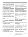
T1.
T2.
T3.
ON/OFF- und Timer-Taste: um die automatische Aus-
schaltung einzustellen:
Leistungsstufe 1: 20 Minuten
Leistungsstufe 2: 15 Minuten
Leistungsstufe 3: 10 Minuten
Intensive Leistungsstufe: 5 Minuten
Taste, um die Leistungsstufe zu verringern
OFF 1: mehrmals betätigen, um die Leistungsstufe
zu reduzieren bis Ausschaltung
OFF 2: während aller Leistungsstufen lange betäti-
gen
ON-Taste, um die Leistungsstufe zu erhöhen
(1-2-3-Intensiv).
Die intensive Leistungsstufe schaltet nach 5 Minuten
automatisch auf Leistungsstufe 2 zurück.
Pagina se încarcă ...
Pagina se încarcă ...
Pagina se încarcă ...
Pagina se încarcă ...
Pagina se încarcă ...
Pagina se încarcă ...
Pagina se încarcă ...
Pagina se încarcă ...
Pagina se încarcă ...
Pagina se încarcă ...
Pagina se încarcă ...
Pagina se încarcă ...
Pagina se încarcă ...
Pagina se încarcă ...
Pagina se încarcă ...
Pagina se încarcă ...
Pagina se încarcă ...
Pagina se încarcă ...
Pagina se încarcă ...
Pagina se încarcă ...
Pagina se încarcă ...
Pagina se încarcă ...
Pagina se încarcă ...
Pagina se încarcă ...
Pagina se încarcă ...
Pagina se încarcă ...
Pagina se încarcă ...
Pagina se încarcă ...
Pagina se încarcă ...
Pagina se încarcă ...
Pagina se încarcă ...
Pagina se încarcă ...
Pagina se încarcă ...
Pagina se încarcă ...
Pagina se încarcă ...
Pagina se încarcă ...
Pagina se încarcă ...
Pagina se încarcă ...
Pagina se încarcă ...
Pagina se încarcă ...
Pagina se încarcă ...
Pagina se încarcă ...
Pagina se încarcă ...
Pagina se încarcă ...
Pagina se încarcă ...
Pagina se încarcă ...
Pagina se încarcă ...
Pagina se încarcă ...
Pagina se încarcă ...
Pagina se încarcă ...
Pagina se încarcă ...
Pagina se încarcă ...
Pagina se încarcă ...
Pagina se încarcă ...
Pagina se încarcă ...
Pagina se încarcă ...
Pagina se încarcă ...
Pagina se încarcă ...
Pagina se încarcă ...
Pagina se încarcă ...
Pagina se încarcă ...
Pagina se încarcă ...
Pagina se încarcă ...
Pagina se încarcă ...
Pagina se încarcă ...
Pagina se încarcă ...
Pagina se încarcă ...
Pagina se încarcă ...
Pagina se încarcă ...
Pagina se încarcă ...
Pagina se încarcă ...
Pagina se încarcă ...
Pagina se încarcă ...
Pagina se încarcă ...
Pagina se încarcă ...
Pagina se încarcă ...
Pagina se încarcă ...
Pagina se încarcă ...
Pagina se încarcă ...
Pagina se încarcă ...
Pagina se încarcă ...
Pagina se încarcă ...
Pagina se încarcă ...
Pagina se încarcă ...
Pagina se încarcă ...
Pagina se încarcă ...
Pagina se încarcă ...
Pagina se încarcă ...
Pagina se încarcă ...
Pagina se încarcă ...
Pagina se încarcă ...
Pagina se încarcă ...
Pagina se încarcă ...
Pagina se încarcă ...
Pagina se încarcă ...
Pagina se încarcă ...
Pagina se încarcă ...
Pagina se încarcă ...
Pagina se încarcă ...
Pagina se încarcă ...
Pagina se încarcă ...
Pagina se încarcă ...
Pagina se încarcă ...
Pagina se încarcă ...
Pagina se încarcă ...
Pagina se încarcă ...
Pagina se încarcă ...
Pagina se încarcă ...
Pagina se încarcă ...
Pagina se încarcă ...
Pagina se încarcă ...
Pagina se încarcă ...
Pagina se încarcă ...
Pagina se încarcă ...
Pagina se încarcă ...
Pagina se încarcă ...
Pagina se încarcă ...
Pagina se încarcă ...
Pagina se încarcă ...
Pagina se încarcă ...
Pagina se încarcă ...
Pagina se încarcă ...
Pagina se încarcă ...
Pagina se încarcă ...
Pagina se încarcă ...
Pagina se încarcă ...
-
 1
1
-
 2
2
-
 3
3
-
 4
4
-
 5
5
-
 6
6
-
 7
7
-
 8
8
-
 9
9
-
 10
10
-
 11
11
-
 12
12
-
 13
13
-
 14
14
-
 15
15
-
 16
16
-
 17
17
-
 18
18
-
 19
19
-
 20
20
-
 21
21
-
 22
22
-
 23
23
-
 24
24
-
 25
25
-
 26
26
-
 27
27
-
 28
28
-
 29
29
-
 30
30
-
 31
31
-
 32
32
-
 33
33
-
 34
34
-
 35
35
-
 36
36
-
 37
37
-
 38
38
-
 39
39
-
 40
40
-
 41
41
-
 42
42
-
 43
43
-
 44
44
-
 45
45
-
 46
46
-
 47
47
-
 48
48
-
 49
49
-
 50
50
-
 51
51
-
 52
52
-
 53
53
-
 54
54
-
 55
55
-
 56
56
-
 57
57
-
 58
58
-
 59
59
-
 60
60
-
 61
61
-
 62
62
-
 63
63
-
 64
64
-
 65
65
-
 66
66
-
 67
67
-
 68
68
-
 69
69
-
 70
70
-
 71
71
-
 72
72
-
 73
73
-
 74
74
-
 75
75
-
 76
76
-
 77
77
-
 78
78
-
 79
79
-
 80
80
-
 81
81
-
 82
82
-
 83
83
-
 84
84
-
 85
85
-
 86
86
-
 87
87
-
 88
88
-
 89
89
-
 90
90
-
 91
91
-
 92
92
-
 93
93
-
 94
94
-
 95
95
-
 96
96
-
 97
97
-
 98
98
-
 99
99
-
 100
100
-
 101
101
-
 102
102
-
 103
103
-
 104
104
-
 105
105
-
 106
106
-
 107
107
-
 108
108
-
 109
109
-
 110
110
-
 111
111
-
 112
112
-
 113
113
-
 114
114
-
 115
115
-
 116
116
-
 117
117
-
 118
118
-
 119
119
-
 120
120
-
 121
121
-
 122
122
-
 123
123
-
 124
124
-
 125
125
-
 126
126
-
 127
127
-
 128
128
-
 129
129
-
 130
130
-
 131
131
-
 132
132
-
 133
133
-
 134
134
-
 135
135
-
 136
136
-
 137
137
-
 138
138
-
 139
139
-
 140
140
-
 141
141
-
 142
142
-
 143
143
-
 144
144
-
 145
145
-
 146
146


ELICA SEE YOU IX/A/90 Manualul proprietarului
- Categorie
- Hote pentru aragaz
- Tip
- Manualul proprietarului
în alte limbi
- slovenčina: ELICA SEE YOU IX/A/90 Návod na obsluhu
Lucrări conexe
Alte documente
-
Indesit H 461 IX.1 Manualul utilizatorului
-
HOTPOINT/ARISTON HHGC 6.7F LB X Manualul utilizatorului
-
Whirlpool WHVS 93F LT BSS Manualul proprietarului
-
HOTPOINT/ARISTON HHGC 6.5F LM X Manualul utilizatorului
-
Samsung HDC6D90TG Manualul proprietarului
-
-
-
Whirlpool HCH 900 IX Manualul utilizatorului
-
Electrolux EFD90567OX Manual de utilizare
-
Gorenje HET945XSC Manual de utilizare