Graphite 59G812 Manual de utilizare
- Categorie
- Accesorii mixer / robot de bucătărie
- Tip
- Manual de utilizare

0
59G812

1
PL INSTRUKCJA ORYGINALNA (OBSŁUGI) ............................................................................................................................................................ 4
EN TRANSLATION (USER) MANUAL ........................................................................................................................................................................ 9
DE ÜBERSETZUNG (BENUTZERHANDBUCH) ...................................................................................................................................................... 14
RU РУКОВОДСТВО ПО ПЕРЕВОДУ (ПОЛЬЗОВАТЕЛЯ) ..................................................................................................................................... 19
HU FORDÍTÁSI (FELHASZNÁLÓI) KÉZIKÖNYV ..................................................................................................................................................... 24
RO MANUAL DE TRADUCERE (UTILIZATOR) ....................................................................................................................................................... 29
UA ОРИГІНАЛЬНА ІНСТРУКЦІЯ (З ЕКСПЛУАТАЦІЇ)............................................................................................................................................ 34
CZ PŘEKLAD (UŽIVATELSKÉ) PŘÍRUČKY ............................................................................................................................................................ 39
SK PREKLAD (POUŽÍVATEĽSKEJ) PRÍRUČKY ..................................................................................................................................................... 44
SL PREVOD (UPORABNIŠKI) PRIROČNIK ............................................................................................................................................................. 48
LT VERTIMO (NAUDOTOJO) VADOVAS ................................................................................................................................................................. 53
LV TULKOŠANAS (LIETOTĀJA) ROKASGRĀMATA ............................................................................................................................................. 58
EE TÕLKIMISE (KASUTAJA) KÄSIRAAMAT .......................................................................................................................................................... 62
BG ПРЕВОД (РЪКОВОДСТВО ЗА ПОТРЕБИТЕЛЯ) ............................................................................................................................................ 67
HR PRIRUČNIK ZA PRIJEVOD (KORISNIK) ........................................................................................................................................................... 73
SR ПРИРУЧНИК ЗА ПРЕВОЂЕЊЕ (КОРИСНИК) ................................................................................................................................................. 77
GR ΕΓΧΕΙΡΊΔΙΟ ΜΕΤΆΦΡΑΣΗΣ (ΧΡΉΣΤΗ) ............................................................................................................................................................ 82
ES MANUAL DE TRADUCCIÓN (USUARIO) ........................................................................................................................................................... 87
IT MANUALE DI TRADUZIONE (UTENTE) .............................................................................................................................................................. 93
NL VERTALING (GEBRUIKERSHANDLEIDING) ..................................................................................................................................................... 98
FR MANUEL DE TRADUCTION (UTILISATEUR)....................................................................................................................................................103

2

3

4
PL
INSTRUKCJA ORYGINALNA (OBSŁUGI)
PILARKA UKOSOWA
59G812
UWAGA: PRZED PRZYSTĄPIENIEM DO UŻYTKOWANIA
ELEKTRONARZĘDZIA NALEŻY UWAŻNIE PRZECZYTAĆ
NINIEJSZĄ INSTRUKCJĘ I ZACHOWAĆ JĄ DO DALSZEGO
WYKORZYSTANIA.
SZCZEGÓŁOWE PRZEPISY BEZPIECZEŃSTWA
Instrukcje bezpieczeństwa dotyczące pilarek do cięcia
ukosowego
• Pilarki do cięcia ukosowego są przeznaczone do cięcia drewna
lub produktów drewnopochodnych, nie można ich używać ze
ściernymi ściernicami do cięcia materiałów żelaznych, takich jak
pręty, płaskowniki, szpilki itp. Pył ścierny blokuje ruchome
części, takie jak opuszczana osłona, powodując ich
zaklinowanie. Iskry powstałe przy cięciu ściernym mogą
uszkodzić opuszczaną osłonę, wkładkę z nacięciem i inne
plastikowe części.
• Użyj zacisków, aby przytrzymać obrabiany przedmiot, gdy tylko
jest to możliwe. Jeśli przytrzymujesz przedmiot ręcznie, musisz
zawsze trzymać rękę w odległości co najmniej 100 mm z każdej
strony tarczy. Nie używaj tej piły do cięcia elementów, które są
zbyt małe, ponieważ nie można ich bezpiecznie zamocować lub
przytrzymać ręcznie. Jeśli dłoń zostanie umieszczona zbyt
blisko tarczy, istnieje zwiększone ryzyko obrażeń na skutek
kontaktu z tarczą.
• Obrabiany przedmiot musi być nieruchomy i zaciśnięty lub
oparty o listwę oporową i stół. Nie podawaj przedmiotu do ostrza
ani nie tnij w żaden sposób „odręcznie”. Nieoparte lub ruchome
elementy mogą być odrzucane z dużą prędkością, powodując
obrażenia.
• Popychaj piłę przez obrabiany przedmiot. Nigdy nie ciągnij piły
przez obrabiany przedmiot. Aby wykonać cięcie, unieś głowicę
piły i wyciągnij ją nad obrabiany przedmiot bez cięcia, uruchom
silnik, naciśnij głowicę piły w dół i popchnij piłę przez obrabiany
przedmiot. Cięcie poprzez pociąganie może spowodować, że
tarcza wspina się na obrabiany przedmiot i gwałtownie rzuci
zespół ostrza w kierunku operatora.
• Nigdy nie krzyżuj dłoni nad zamierzoną linią cięcia, ani z przodu,
ani z tyłu piły. Podparcie obrabianego przedmiotu „ręką
skrzyżowaną”, tj. przytrzymanie obrabianego przedmiotu po
prawej stronie tarczy piły lewą ręką lub odwrotnie, jest bardzo
niebezpieczne.
• Nie sięgaj do osłony żadną ręką bliżej niż 100 mm z każdej
strony tarczy, aby usunąć resztki drewna lub z jakiegokolwiek
innego powodu podczas gdy tarcza się obraca. Bliskość
obracającej się tarczy do dłoni może nie być oczywista i
spowodować poważne obrażenia.
• Sprawdź obrabiany przedmiot przed cięciem. Jeśli obrabiany
przedmiot jest wygięty lub wypaczony, dociśnij go zewnętrzną,
pochyloną powierzchnią w kierunku listwy oporowej. Zawsze
upewnij się, że nie ma odstępu między przedmiotem, listwą
oporową i stołem wzdłuż linii cięcia. Wygięte lub wypaczone
elementy mogą się skręcać lub przesuwać i mogą powodować
klinowanie się wirującej tarczy podczas cięcia. W obrabianym
elemencie nie powinny znajdować się gwoździe ani inne ciała
obce.
• Nie używaj pilarki, dopóki nie usuniesz z jej stołu wszystkich
narzędzi, ścinków drewna itp., z wyjątkiem przedmiotu
obrabianego. Małe śmieci, luźne kawałki drewna lub inne
przedmioty, które zetkną się z obracającą tarczą, mogą zostać
wyrzucone z dużą prędkością.
• Obrabiaj tylko jeden przedmiot naraz. Wiele przedmiotów
ułożonych w stos nie może być odpowiednio zaciśnięte lub
usztywnione i może zakleszczyć się na tarczy lub przesunąć
podczas cięcia.
• Upewnij się przed użyciem, że pilarka ukosowa jest
zamontowana lub ustawiona na poziomej, twardej powierzchni
roboczej. Pozioma i twarda powierzchnia robocza zmniejsza
ryzyko niestabilności piły ukosowej.
• Zaplanuj swoją pracę. Za każdym razem, gdy zmieniasz
ustawienie kąta głowicy lub kąta stołu, upewnij się, że
regulowana część listwy oporowej ustawiona jest prawidłowo,
aby podeprzeć obrabiany przedmiot i nie będzie kolidowała z
tarczą lub systemem zabezpieczającym. Bez włączania
narzędzia w pozycji „ON” i bez przedmiotu obrabianego na
stole, przesuń tarczę przez pełne symulowane cięcie, aby
upewnić się, że nie będzie żadnych zakłóceń ani
niebezpieczeństwa przecięcia listwy oporowej.
• Zapewnij odpowiednie podparcie, takie jak przedłużenia stołu,
piły, itp. dla przedmiotu, który jest szerszy lub dłuższy niż blat
stołu roboczego. Przedmioty obrabiane dłuższe lub szersze niż
stół pilarki ukosowej mogą się przechylić, jeśli nie zostaną
bezpiecznie podparte. Jeśli odcięty kawałek lub przedmiot
obrabiany przechyli się, może podnieść opuszczaną osłonę lub
zostać rzucony przez obracającą się tarczę.
• Nie używaj innej osoby jako substytutu przedłużenia stołu lub
jako dodatkowego wsparcia. Niestabilne podparcie przedmiotu
obrabianego może spowodować zaklinowanie tarczy lub
przesunięcie przedmiotu obrabianego podczas operacji cięcia,
wciągając ciebie i pomocnika w wirującą tarczę.
• Odcięty element nie może być zablokowany ani dociśnięty w
jakikolwiek sposób do obracającej się tarczy. W przypadku
ograniczenia, tj. przy użyciu ograniczników długości, odcinany
odcinek mógłby zostać zaklinowany o tarczę i gwałtownie
odrzucony.
• Zawsze używaj zacisku lub uchwytu zaprojektowanego do
właściwego podparcia okrągłego materiału, takiego jak pręty lub
rurki. Pręty mają tendencję do toczenia się podczas cięcia,
powodując „ugryzienie” przez tarczę i wciągnięcie przedmiotu
wraz z dłonią do tarczy.
• Pozwól tarczy osiągnąć pełną prędkość przed dotknięciem do
przedmiotu obrabianego. Zmniejszy to ryzyko wyrzucenia
przedmiotu obrabianego.
• Jeśli przedmiot lub tarcza zakleszczy się, wyłącz pilarkę
ukosową. Poczekaj, aż wszystkie ruchome części się
zatrzymają i odłącz wtyczkę od źródła zasilania i / lub wyjmij
akumulator. Następnie uwolnij zablokowany materiał. Dalsze
piłowanie z zablokowanym przedmiotem może spowodować
utratę kontroli lub uszkodzenie piły ukośnej.
• Po zakończeniu cięcia zwolnij łącznik, przytrzymaj głowicę
pilarki w dole i poczekaj, aż ostrze zatrzyma się, zanim wyjmiesz
odcinany element. Zbliżenie dłoni do obracającej się jeszcze
tarczy jest niebezpieczne.
• Trzymaj mocno uchwyt podczas wykonywania niepełnego
cięcia lub zwalniania łącznika, zanim głowica piły znajdzie się
całkowicie w dolnym położeniu. Hamowanie piły może
spowodować gwałtowne pociągnięcie głowicy w dół, co grozi
obrażeniami.
UWAGA! Urządzenie służy do pracy wewnątrz pomieszczeń.
Mimo zastosowania konstrukcji bezpiecznej z samego
założenia, stosowania środków zabezpieczających i
dodatkowych środków ochronnych, zawsze istnieje ryzyko
szczątkowe doznania urazów podczas pracy.
OBJAŚNIENIE ZASTOSOWANYCH PIKTOGRAMÓW
1. Uwaga! Zachowaj szczególne środki ostrożności
2. OSTRZEŻENIE Przeczytaj instrukcję obsługi
3. Używaj środki ochrony osobistej (gogle ochronne, ochronniki
słuchu, maskę przeciwpyłową)
4. Używaj odzieży ochronnej
5. Odłącz przewód zasilający przed rozpoczęciem czynności
obsługowych lub naprawczych
6. Nie dopuszczać dzieci do narzędzia
7. Chroń urządzenie przed wilgocią
8. Druga klasa ochronności
9. Niebezpieczeństwo! Uważaj na dłonie

5
10. Uwaga promieniowanie laserowe! Nie patrzeć w promień
lasera.
Stół roboczy po każdej stronie tarczy powinien być oznaczony
znakiem
BUDOWA I ZASTOSOWANIE
Pilarka ukosowa to urządzenie wyposażone w podstawę z
możliwością zmiany kąta przymocowanej do niej głowicy tnącej.
Dodatkowo głowica pilarki ukosowej, w zależności od konstrukcji,
może pochylać się pod kątem oraz być wysuwana dla zwiększenia
funkcjonalności i długości cięcia.
Pilarka ukosowa przeznaczona jest do przecinania kawałków drewna,
pasujących do wielkości urządzenia. Nie należy stosować jej do
przecinania drewna opałowego. Pilarkę należy stosować wyłącznie
zgodnie z jej przeznaczeniem. Próby użycia pilarki do innych celów
niż podano będzie traktowane jako użytkowanie niewłaściwe. Pilarkę
należy wykorzystywać wyłącznie z odpowiednimi tarczami tnącymi, z
zębami z nakładkami z węglików spiekanych. Pilarka ukosowa to
urządzenie do stosowania zarówno przy pracach warsztatowych
stolarskich jak i konstrukcyjnych ciesielskich.
Nie wolno stosować urządzenia niezgodnie z jego
przeznaczeniem!
OPIS STRON GRAFICZNYCH
Poniższa numeracja odnosi się do elementów urządzenia
przedstawionych na stronach graficznych niniejszej instrukcji.
1. Uchwyt transportowy
2. Uchwyt rękojeści
3. Przycisk blokady włącznika
4. Włącznik
5.
6. Przycisk blokady wrzeciona
7. Osłona tarczy tnącej
8. Pokrywa szczotki węglowej
9. Sworzeń blokady głowicy
10. Ogranicznik głębokości cięcia
11. Śruba ogranicznika głębokości cięcia
12. Pokrętło blokady prowadnicy
13. Prowadnica
14. Dźwignia blokady głowicy
15. Listwa oporowa
16. Przedłużacz stołu
17. Ogranicznik krańcowy
18. Pokrętło blokady przedłużacza stołu
19. Otwór montażowy
20. Podziałka kątowa stołu roboczego
21. Wskaźnik kąta stołu roboczego
22. Dźwignia automatycznego ustalania
23. Pokrętło blokady stołu roboczego
24. Wkładka stołu
25. Stół roboczy
26. Moduł laserowy
27. Osłona stała
28. Króciec odprowadzania pyłu
29. Worek na pył
30. Pokrętło mocujące docisk pionowy
31. Ramię docisku pionowego
32. Pokrętło blokady ramienia docisku pionowego
33. Pokrętło mocowania materiału
34. Podziałka kątowa nachylenia głowicy
35. Wskaźnik kąta nachylenia głowicy
36. Zasobnik na baterie
37. Przycisk włącznika lasera
38. Laser
39. Śruby mocujące moduł laserowy
40. Śruba mocowania płyty centralnej
41. Płyta centralna
42. Śruba regulacyjna kąta 0”
43. Śruba regulacyjna kąta 45”
* Mogą występować różnice między rysunkiem a wyrobem.
WYPOSAŻENIE I AKCESORIA
Worek na pył - 1 szt
Klucz specjalny - 1 szt
Docisk pionowy - 1 szt
PRZYGOTOWANIE DO PRACY
Przed przystąpieniem do jakichkolwiek czynności montażowych
lub regulacyjnych przy pilarce ukosowej należy upewnić się, że
została ona odłączona od zasilania.
PRZENOSZENIE PILARKI UKOSOWEJ
• Przy przenoszeniu pilarki należy mieć pewność, że jej głowica
została zabezpieczona w skrajnym dolnym położeniu.
• Sprawdzić czy pokrętło blokady stołu roboczego, dźwignia
blokady głowicy i inne elementy zabezpieczające są pewnie
dokręcone.
MONTOWANIE PILARKI UKOSOWEJ NA STOLE
WARSZTATOWYM
Zaleca się, aby pilarka była zamocowana do stołu warsztatowego
lub stojaka wykorzystując przewidziane do tego otwory montażowe
(19) w podstawie pilarki, co gwarantuje bezpieczne jej działanie i
eliminuje ryzyko niepożądanych przemieszczeń urządzenia w
czasie pracy. Otwory montażowe pozwalają na zastosowanie śrub
o średnicy 8 mm z łbem zamkowym lub sześciokątnym.
Podczas montażu pilarki do blatu stołu warsztatowego należy
upewnić się czy:
• Powierzchnia blatu stołu warsztatowego jest płaska i czysta.
• Śruby są dokręcone równo i nie z nadmierną siłą (śruby
mocujące należy dokręcać tak, aby nie nastąpiło naprężenie
albo odkształcenie podstawy). W przypadku nadmiernego
naprężenia istnieje niebezpieczeństwo pęknięcia podstawy.
ODPROWADZANIE PYŁU
Aby zapobiec gromadzeniu się pyłu i zapewnić maksymalną wydajność
pracy można podłączyć pilarkę do odkurzacza przemysłowego,
wykorzystując króciec odprowadzania pyłu (28). Alternatywnie zbieranie
pyłu jest możliwe do worka na pył (w dostawie) po jego zamocowaniu do
króćca odprowadzania pyłu. Montaż przeprowadza się poprzez
nałożenie worka na pył (29) na króciec odprowadzania pyłu (28) (rys. A).
Aby opróżnić worek na pył należy zdjąć go z króćca odprowadzenia pyłu
i otworzyć zamek błyskawiczny, pozwalający na pełny dostęp do
wnętrza worka.
Aby uzyskać optymalne odprowadzanie pyłu należy worek na pył
opróżniać, gdy zostanie wypełniony w 2/3 swojej objętości.
OPEROWANIE RAMIENIEM WYSIĘGNIKOWYM (GŁOWICĄ)
Ramię wysięgnikowe ma dwa położenia górne i dolne. Aby zwolnić
ramię wysięgnikowe z zablokowanego położenia dolnego należy:
• Nacisnąć ramię wysięgnikowe i trzymać przyciśnięte ku dołowi.
• Odciągnąć sworzeń blokady głowicy (9).
• Podtrzymywać ramię wysięgnikowe w miarę jak podnosi się ono
do swego położenia górnego.
• Aby zablokować ramię wysięgnikowe w dolnym położeniu
należy:
• Zblokować ramię wysięgnikowe w tym położeniu, wsuwając
trzpień sworznia blokady głowicy (9).
DOCISK PIONOWY
Docisk pionowy (rys. B) może być montowany w podstawie pilarki
po obu stronach stołu roboczego i daje się w pełni przystosować do
wielkości materiału przecinanego. Nie wolno pracować pilarką, jeśli
nie został użyty docisk pionowy.
• Poluzować pokrętło mocujące docisk pionowy (30) do podstawy
po stronie po której będzie montowany docisk pionowy.
• Zamontować docisk pionowy poprzez wsunięcie go w otwór w
podstawie pilarki i dokręcić pokrętło mocujące docisk pionowy
(30). do podstawy pilarki.
• Po dostosowaniu pozycji ramienia docisku pionowego (31) do
obrabianego materiału dokręcić pokrętło blokady ramienia
docisku pionowego (32) i pokrętło mocowania materiału (33).
• Sprawdzić czy materiał jest stabilnie zamontowany.
PRACA / USTAWIENIA
Przed przystąpieniem do jakichkolwiek czynności regulacyjnych
przy pilarce trzeba się upewnić, że została ona odłączona od sieci

6
zasilającej. Aby zapewnić sobie bezpieczne, dokładne i wydajne
działanie pilarki, należy wszystkie procedury regulacyjne
wykonywać w całości.
Po zakończeniu wszystkich czynności regulacyjnych i
nastawczych należy upewnić się, że zostały zabrane wszystkie
klucze. Sprawdzić czy wszystkie gwintowane elementy złączne są
odpowiednio dokręcone.
Dokonując czynności regulacyjnych sprawdzić czy wszystkie
elementy zewnętrzne działają prawidłowo i są w dobrym stanie.
Jakakolwiek część zużyta czy uszkodzona powinna zostać
wymieniona przez wykwalifikowany personel przed rozpoczęciem
użytkowania pilarki.
WŁĄCZANIE / WYŁĄCZANIE
Napięcie sieci musi odpowiadać wielkości napięcia podanego na
tabliczce znamionowej pilarki.
Pilarkę można włączać tylko wtedy, gdy tarcza tnąca jest
odsunięta od materiału przewidzianego do obróbki.
Pilarka ukosowa posiada przycisk blokady włącznika (3),
zabezpieczający przed przypadkowym uruchomieniem.
Włączanie
Wcisnąć przycisk blokady włącznika (3).
Wcisnąć i przytrzymać przycisk włącznika (4).
Wyłączanie
Zwolnić nacisk na przycisk włącznika (4).
OBSŁUGA PRZEDŁUŻACZY STOŁU
Przedłużacze stołu (16) znajdują się po obu stronach podstawy
pilarki.
• Odblokować pokrętła blokady przedłużacza stołu (18) (rys. C).
• Wyregulować długość przedłużaczy stołu.
• Zamocować za pomocą pokręteł blokady przedłużacza stołu
(18).
• W razie potrzeby można skorzystać z odchylanych
ograniczników krańcowych (17) ułatwiających cięcie na wymiar.
OBSŁUGA OGRANICZNIKA GŁĘBOKOŚCI CIĘCIA
Ogranicznik głębokości cięcia może być użyty w przypadku gdy
zaistnieje konieczność wykonania wpustu w materiale. Odbywa
się to poprzez nacięcie powierzchniowe obrabianego materiału
gdy tarcza nie pracuje pełną możliwą głębokością.
• Zablokować dźwignię blokady głowicy (14).
• Poluzować pokrętło blokady prowadnicy (12) i przesunąć
głowicę do tyłu.
• Dokręcić pokrętło blokady prowadnicy (12).
• Przekręcić ogranicznik głębokości cięcia (10) w ustawienie do
pracy z ograniczoną głębokością cięcia (rys. D).
• Opuścić w dół ramię wysięgnikowe i trzymać je w położeniu
dolnym, oparte o ogranicznik głębokości przecinania.
• Pokręcać (w lewo lub w prawo) śrubą ogranicznika głębokości
cięcia (11) (rys. D) do uzyskania pożądanego zagłębienia tarczy
tnącej.
• Poluzować pokrętło blokady prowadnicy (12).
• Wykonać planowane cięcia na zadaną głębokość.
• Aby powrócić do cięcia na pełną głębokość należy przekręcić
ogranicznik głębokości cięcia (10) w pozycję w której po
opuszczeniu w dół ramienia wysięgnikowego śruba
ogranicznika głębokości cięcia (11) nie styka się z
ogranicznikiem głębokości cięcia (10).
USTAWIENIE STOŁU ROBOCZEGO DLA OPERACJI
PRZECINANIA POD KĄTEM
Obrotowe ramię wysięgnikowe pozwala na przecinanie materiału pod
dowolnym kątem od położenia prostopadłego do 45° w lewo lub w
prawo.
• Odciągnąć sworzeń blokady głowicy (9) zezwalając, aby ramię
wysięgnikowe powoli uniosło się do położenia górnego.
• Poluzować pokrętło blokady stołu roboczego (23).
• Wcisnąć i przytrzymać dźwignię automatycznego ustalania (22)
i obrócić ramię wysięgnikowe w lewo lub w prawo, do
osiągnięcia wskazania pożądanej wartości kąta na podziałce
kątowej stołu roboczego (20).
• Zablokować dokręcając pokrętło blokady stołu roboczego (23).
• Podziałka kątowa stołu roboczego (20) ma szereg
zaznaczonych położeń w których następuje wstępne
automatyczne ustalenie obrotowego ramienia wysięgnikowego.
Może to mieć miejsce tylko gdy podczas obrotu ramienia
wysięgnikowego dźwignia automatycznego ustalania (22) nie
jest przytrzymywana w pozycji wciśniętej i może się zablokować
w tych wytypowanych fabrycznie położeniach. Są to najczęściej
stosowane kąty przecinania (15°, 22,5°, 30°, 45° w lewo /
prawo). Ustawienie dowolnego kąta można dokładnie
wyregulować, korzystając z podziałki kątowej stołu roboczego
(20) wyskalowanej, co jeden stopień. Mimo, że podziałka jest
wystarczająco dokładna dla większości wykonywanych prac, to
jednak zaleca się sprawdzenie ustawienia kąta przecinania za
pomocą kątomierza lub innego przyrządu do mierzenia kątów.
SPRAWDZENIE I REGULACJA PROSTOPADŁEGO
USTAWIENIA TARCZY TNĄCEJ WZGLĘDEM STOŁU
ROBOCZEGO.
• Poluzować dźwignię blokady głowicy (14).
• Ustawić głowicę w położeniu 0° (prostopadłym w stosunku do
stołu roboczego) i dokręcić dźwignię blokady głowicy (14).
• Poluzować pokrętło blokady stołu roboczego (23), wcisnąć i
przytrzymać dźwignię automatycznego ustalania (22).
• Ustawić stół roboczy w położenie 0°, zwolnić dźwignię
automatycznego ustalania i dokręcić pokrętło blokady stołu
roboczego (23).
• Opuścić głowicę pilarki do skrajnego położenia dolnego.
• Sprawdzić (za pomocą przyrządu) prostopadłość ustawienia
tarczy tnącej względem stołu roboczego.
Podczas dokonywania pomiarów należy upewnić się, aby
przyrząd pomiarowy nie dotykał do zęba tarczy tnącej gdyż ze
względu na grubości nakładki z węglika spiekanego pomiar
może być niedokładny.
Jeśli zmierzony kąt nie wynosi 90° to konieczna jest regulacja, którą
przeprowadza się następująco:
• Poluzować nakrętkę zabezpieczającą i obracać śrubę
regulacyjną kąta 0° (42) (rys. E) w prawo lub w lewo, aby
zwiększyć lub zmniejszyć kąt nachylenia tarczy tnącej.
• Po ustawieniu prostopadłego położenia tarczy tnącej względem
stołu roboczego zezwolić głowicy na powrót do położenia
górnego.
• Przytrzymując śrubę regulacyjną kąta 0° (42) dokręcić nakrętkę
zabezpieczającą.
• Opuścić głowicę w dół i ponownie sprawdzić czy ustawiony kąt
odpowiada wskazaniom na podziałce kątowej nachylenia
głowicy (34), jeśli trzeba - dokonać regulacji usytuowania
wskaźnika kąta nachylenia głowicy (35) (rys. E).
• Podobną regulację należy przeprowadzić dla kąta 45° przechyłu
głowicy dla cięcia ukosowego wykorzystując śrubę regulacyjną
kąta 45° (43) (rys. E).
SPRAWDZENIE I REGULACJA PROSTOPADŁEGO
USTAWIENIA TARCZY TNĄCEJ WZGLĘDEM LISTWY
OPOROWEJ.
Tę procedurę należy wykonywać zawsze w przypadku, gdy
listwa oporowa była demontowana lub wymieniana. Ta regulacja
może być wykonana dopiero po prostopadłym ustawieniu tarczy
tnącej względem stołu roboczego. Listwa oporowa służy jako
ogranicznik dla materiału przecinanego.
• Poluzować pokrętło blokady stołu roboczego (23), wcisnąć i
przytrzymać dźwignię automatycznego ustalania (22) i ustawić
stół roboczy w położenie 0°.
• Opuścić głowicę pilarki do skrajnego położenia dolnego.
• Przyłożyć do tarczy tnącej kątomierz lub inny przyrząd do
mierzenia kątów.
• Dosunąć przyrząd do mierzenia kątów do listwy oporowej (15).
• Pomiar powinien wykazać 90°.
• Jeśli zachodzi potrzeba regulacji należy:
• Poluzować śruby mocujące listwę oporową (15) do podstawy.
• Wyregulować położenie listwy oporowej (15) tak, aby była
prostopadła do tarczy tnącej.
• Dokręcić śruby mocujące listwę oporową.
USTAWIENIE RAMIENIA WYSIĘGNIKOWEGO (GŁOWICY) DLA
OPERACJI PRZECINANIA UKOSOWEGO
Ramię wysięgnikowe może być nachylane pod dowolnym kątem w
zakresie od 0° do 45° – dla przecinania ukosowego (rys. E).

7
• Odciągnąć sworzeń blokady głowicy (9) zwalniając ramię
wysięgnikowe i zezwalając, aby ramię wysięgnikowe powoli
uniosło się do położenia górnego.
• Poluzować dźwignię blokady głowicy (14).
• Nachylić ramię wysięgnikowe w lewo pod pożądanym kątem,
który można odczytać na podziałce kątowej nachylenia głowicy
(34) wykorzystując wskaźnik kąta nachylenia głowicy (35) (rys.
E).
• Dokręcić dźwignię blokady głowicy (14).
Jeśli zachodzi potrzeba wyregulowania ustawienia obu kątów
(w obu płaszczyznach, poziomej i pionowej), dla przecinania
kombinowanego, to zawsze w pierwszej kolejności należy
ustawiać kąt przecinania ukosowego.
SPRAWDZENIE DZIAŁANIA LASERA
Zespół urządzenia laserowego wysyła wiązkę światła laserowego
pokazującą linię na materiale, po której będzie przebiegało
przecinanie tarczą tnącą. Odpowiednie ustawienie linii padania
wiązki laserowej zostało wyregulowane podczas procesu
produkcyjnego. Niemniej przy pracach precyzyjnych ustawienie
powinno zostać sprawdzone przed przystąpieniem do operacji
cięcia.
• Umieścić baterie w zasobniku na baterie (36) (rys. F)
upewniając się, że zachowana jest właściwa biegunowość.
• Ustawić stół roboczy w położeniu, dla którego wskaźnik kąta
stołu roboczego (21) pokrywa się z punktem 0° na podziałce
kątowej stołu roboczego (20), a wskaźnik kąta nachylenia
głowicy (35) (rys. E) pokrywa się z punktem 0° na podziałce
kątowej nachylenia głowicy (34) (rys. E).
• Zamocować na stole roboczym (25) odpowiedni kawałek
materiału odpadowego i wykonać cięcie.
• Zwolnić ramię wysięgnikowe i pozostawić materiał odpadowy
zamocowany na stole roboczym pilarki.
• Ustawić przycisk włącznika lasera (37) w położenie włączony „I”
(oznakowane).
• Rzutowana wiązka światła powinna być równoległa do rzazu po
cięciu.
REGULACJA LASERA
Przy ustawianiu wiązki prowadzącej lasera nie wolno patrzeć
bezpośrednio na wiązkę lub jej odbicie na powierzchni lustrzanej.
Zespół urządzenia laserowego należy wyłączać, jeśli laser nie jest
wykorzystywany.
Jeśli wiązka światła lasera nie jest równoległa do rzazu po cięciu
należy:
• Delikatnie obrócić w lewo lub prawo laser (38) (rys. G) w
obudowie modułu laserowego (26) do momentu uzyskania
równoległego położenia wiązki światła laserowego. Nie należy
obracać modułu laserowego na siłę i więcej niż kilka stopni.
• W przypadku, gdy zachodzi konieczność regulacji poprzecznej
poluzować śruby mocujące moduł laserowy (39) i przesunąć
moduł laserowy w lewo lub prawo, aż do uzyskania
równoległości linii laserowej do rzazu po cięciu.
Pył powstały przy cięciu może przytłumić światło lasera, dlatego
też, co jakiś czas trzeba oczyścić soczewkę projektora lasera.
URUCHOMIENIE PILARKI
Przed naciśnięciem przycisku włącznika należy upewnić się czy
pilarka została właściwie zmontowana i wyregulowana, zgodnie ze
wskazówkami podanymi w niniejszej instrukcji.
Opisywana pilarka została zaprojektowana dla osób praworęcznych.
• Wcisnąć przycisk blokady włącznika (3).
• Nacisnąć przycisk włącznika (4).
• Zezwolić, aby silnik pilarki osiągnął pełną prędkość obrotową.
• Obniżyć ramię wysięgnikowe ku materiałowi obrabianemu.
• Wykonać cięcie.
ZATRZYMANIE PILARKI
• Zwolnić nacisk na przycisk włącznika (4) i odczekać, aż tarcza
całkowicie przestanie się obracać.
• Unieść ramię wysięgnikowe pilarki, odsuwając je od materiału
przecinanego.
Chwilowe iskrzenie szczotek we wnętrzu silnika elektrycznego
jest zjawiskiem normalnym w czasie uruchamiania i
zatrzymywania się pilarki. Nie wolno zatrzymywać tarczy tnącej
pilarki wywierając na nią nacisk boczny.
CIĘCIE PILARKĄ
Należy tak mocować materiał przecinany, aby nie przeszkadzało
to w posługiwaniu się pilarką. Przed włączeniem pilarki
przesunąć jej głowicę w położenie dolne w celu upewnienia się,
że głowica pilarki i osłona tarczy tnącej maja pełną swobodę
ruchu. Upewnić się czy osłona tarczy tnącej w swoim ruchu
dochodzi do położenia skrajnego.
Przed przystąpieniem do cięcia upewnić się czy pokrętło blokady stołu
roboczego (23) oraz dźwignia blokady głowicy (14) pilarki są dokręcone w
sposób pewny.
• Podłączyć pilarkę do sieci.
• Upewnić się, że przewód zasilający jest z dala od tarczy tnącej
i podstawy urządzenia.
• Umieścić materiał na stole roboczym i upewnić się, że jest on
pewnie zamocowany, aby nie mógł poruszyć się w czasie cięcia.
• Przesunąć głowicę pilarki w skrajne tylne położenie i
zablokować prowadnicę (13) pokrętłem blokady prowadnicy
(12).
• Odblokować głowicę i osłonę tarczy tnącej.
• Nacisnąć przycisk blokady włącznika i uruchomić pilarkę
włącznikiem (odczekać, aż tarcza tnąca pilarki osiągnie swoją
maksymalna prędkość obrotową).
• Powoli opuszczać głowicę pilarki.
• Rozpocząć przecinanie wywierając umiarkowaną siłę na
głowicę podczas cięcia.
Niedostateczne dokręcenie pokręteł blokady może spowodować
niespodziewane przesunięcie się tarczy tnącej na górną
powierzchnię materiału, co zagraża operatorowi niebezpiecznym
uderzeniem kawałkiem materiału.
PRZECINANIE Z PRZESUWEM RAMIENIA WYSIĘGNIKOWEGO
(GŁOWICY) PILARKI
Przesuw ramienia wysięgnikowego pilarki umożliwia ruch tarczy tnącej do
przodu i do tyłu pozwalając na przecinanie szerszych kawałków materiału.
• Ustawić ramię wysięgnikowe w górnym położeniu.
• Poluzować pokrętło blokady prowadnicy (12).
• Przed włączeniem pilarki pociągnąć ramię wysięgnikowe ku
sobie, trzymając je w górnym położeniu.
• Nacisnąć przycisk blokady włącznika (3) i uruchomić pilarkę.
• Zwolnić ramię wysięgnikowe i odczekać aż tarcza tnąca
osiągnie swoją prędkość maksymalną.
• Uwolnić osłonę tarczy tnącej.
• Obniżyć ramię wysięgnikowe i rozpocząć cięcie.
• Podczas cięcia przesuwać ramię wysięgnikowe do tyłu (od
siebie).
• Po przecięciu materiału zwolnić nacisk na przycisk włącznika i
odczekać aż tarcza tnąca przestanie się obracać przed
uniesieniem ramienia wysięgnikowego do górnego położenia.
Nigdy nie wolno dokonywać cięcia przesuwając głowicę pilarki
ku sobie. Tarcza tnąca pilarki mogłaby niespodziewanie wspiąć
się na materiał przecinany, co zagraża operatorowi
niebezpiecznym zjawiskiem odbicia.
OBSŁUGA I KONSERWACJA
Przed przystąpieniem do jakichkolwiek czynności związanych z
instalowaniem, regulacją, naprawą lub obsługą należy wyjąć
wtyczkę przewodu zasilającego z gniazdka sieciowego.
CZYSZCZENIE
• Po zakończeniu pracy starannie usunąć wszelkie kawałki
materiału, wióry i pył z wkładki stołu roboczego oraz obszaru
wokół tarczy tnącej i jej osłony.
• Upewnić się, że szczeliny wentylacyjne obudowy silnika są
drożne i nie ma w nich wiórów czy pyłu.
• Oczyścić prowadnice i pokryć je cienką warstwą smaru stałego.
• Utrzymywać w stanie czystym wszystkie rękojeści i pokrętła.
• Pędzelkiem oczyścić soczewkę projektora laserowego.
WYMIANA TARCZY TNĄCEJ
• Unieść osłonę tarczy tnącej (7) i wykręcić śrubę mocowania
płyty centralnej (40) (rys. H).

8
• Odsunąć płytę centralną (41) w lewo tak, aby zapewnić dostęp
do śruby mocującej tarczę tnącą.
• Nacisnąć przycisk blokady wrzeciona (6) i obracać tarczą tnącą,
aż do jej zablokowania.
• Posługując się kluczem specjalnym (w dostawie) poluzować i
wykręcić śrubę mocującą tarczę tnącą.
• Zdjąć podkładkę zewnętrzną i wyjąć tarczę tnącą (zwracając
uwagę na pierścień redukcyjny jeśli występuje).
• Usunąć wszelkie zanieczyszczenia z wrzeciona i podkładek
mocujących tarczę tnącą.
• Zamontować nową tarczę tnącą wykonując opisane czynności
w kolejności odwrotnej.
• Po zakończeniu należy upewnić się czy wszystkie klucze i
narzędzia regulacyjne zostały usunięte i czy wszystkie śruby,
pokrętła i wkręty są pewnie dokręcone.
Śruba zabezpieczająca tarczę tnącą ma lewy gwint. Należy
zachować szczególną uwagę przy chwytaniu tarczy tnącej.
Trzeba korzystać z rękawic ochronnych w celu zapewnienia
ochrony rękom, przed kontaktem z ostrymi zębami tarczy tnącej.
WYMIANA BATERII W MODULE LASEROWYM
Moduł laserowy zasilany jest przez dwie baterie 1,5 V typu AAA.
• Otworzyć pokrywę zasobnika na baterie (36) (rys. F).
• Usunąć zużyte baterie.
• Włożyć nowe baterie, upewniając się czy zachowana jest
właściwa biegunowość.
• Zamontować pokrywę zasobnika na baterie.
WYMIANA SZCZOTEK WĘGLOWYCH
Zużyte (krótsze niż 5 mm), spalone lub pęknięte szczotki węglowe silnika
należy natychmiast wymienić. Zawsze dokonuje się jednocześnie
wymiany obu szczotek.
• Odkręcić pokrywy szczotek węglowych (8).
• Wyjąć zużyte szczotki.
• Usunąć ewentualny pył węglowy, za pomocą sprężonego
powietrza.
• Włożyć nowe szczotki węglowe (szczotki powinny swobodnie
wsunąć się do szczotkotrzymaczy).
• Zamontować pokrywy szczotek węglowych (8).
Po wykonaniu czynności wymiany szczotek węglowych należy
uruchomić elektronarzędzie bez obciążenia i odczekać 1-2 min,
aż szczotki węglowe dopasują się do komutatora silnika.
Czynność wymiany szczotek węglowych należy powierzyć
wyłącznie osobie wykwalifikowanej wykorzystując części
oryginalne.
Wszelkiego rodzaju usterki powinny być usuwane przez
autoryzowany serwis producenta.
PARAMETRY TECHNICZNE
DANE ZNAMIONOWE
Pilarka ukosowa 59G812
Parametr
Wartość
Napięcie zasilania
230V AC 50Hz
Moc znamionowa
1800 W
Prędkość obrotowa tarczy (bez
obciążenia)
4800 min-1
Rodzaj pracy
S6 25%
Długość prowadnicy
195 mm
Zakres cięcia kątowego
± 45°
Zakres cięcia ukośnego
0° ÷ 45°
Maksymalna głębokość cięcia
75 mm
Średnica zewnętrzna tarczy tnącej
254 mm
Średnica wewnętrzna tarczy tnącej
30 mm
Wymiary przecinanego
materiału pod
kątem / pod skosem
0° x 0°
90 x 280mm
45° x
0°
90 x 200mm
45° x
45°
50 x 200mm
0° x
45°
50 x 280mm
Klasa lasera
II
Moc lasera
< 1mW
Długość fali świetlnej lasera
λ = 650 nm
Klasa ochronności
II
Stopień ochrony IP
IPX0
Masa
15,72 kg
Rok produkcji
59G812 oznacza zarówno typ oraz określenie maszyny
DANE DOTYCZĄCE HAŁASU I DRGAŃ
Poziom ciśnienia akustycznego
LpA=95,2 dB(A) K= 3
dB(A)
Poziom mocy akustycznej
LwA=108,2 dB(A) K=
3 dB(A)
Wartość przyspieszeń drgań
ah = 2,936 m/s²
K=1,5 m/s2
Informacje na temat hałasu i wibracji
Poziom emitowanego hałasu przez urządzenie opisano poprzez:
poziom emitowanego ciśnienia akustycznego LpA oraz poziom
mocy akustycznej LwA (gdzie K oznacza niepewność pomiaru).
Drgania emitowane przez urządzenie opisano poprzez wartość
przyśpieszeń drgań ah (gdzie K oznacza niepewność pomiaru).
Podane w niniejszej instrukcji: poziom emitowanego ciśnienia
akustycznego LpA, poziom mocy akustycznej LwA oraz wartość
przyśpieszeń drgań ah zostały zmierzone zgodnie z normą EN
62841-1:2015. Podany poziom drgań ah może zostać użyty do
porównywania urządzeń oraz do wstępnej oceny ekspozycji na
drgania.
Podany poziom drgań jest reprezentatywny jedynie dla
podstawowych zastosowań urządzenia. Jeżeli urządzenie zostanie
użyte do innych zastosowań lub z innymi narzędziami roboczymi,
poziom drgań może ulec zmianie. Na wyższy poziom drgań będzie
wpływać niewystarczająca czy zbyt rzadka konserwacja
urządzenia. Podane powyżej przyczyny mogą spowodować
zwiększenie ekspozycji na drgania podczas całego okresu pracy.
Aby dokładnie oszacować ekspozycję na drgania, należy
uwzględnić okresy kiedy urządzenie jest wyłączone lub kiedy
jest włączone ale nie jest używane do pracy. Po dokładnym
oszacowaniu wszystkich czynników łączna ekspozycja na
drgania może okazać się znacznie niższa.
W celu ochrony użytkownika przed skutkami drgań należy
wprowadzić dodatkowe środki bezpieczeństwa, takie jak: cykliczna
konserwacja urządzenia i narzędzi roboczych, zabezpieczenie
odpowiedniej temperatury rąk oraz właściwa organizacja pracy.
OCHRONA ŚRODOWISKA
Produktów zasilanych elektrycznie nie należy wyrzucać wraz
z domowymi odpadkami, lecz oddać je do utylizacji w
odpowiednich zakładach. Informacji na temat utylizacji udzieli
sprzedawca produktu lub miejscowe władze. Zużyty sprzęt
elektryczny i elektroniczny zawiera substancje nieobojętne dla
środowiska naturalnego. Sprzęt nie poddany recyclingowi
stanowi potencjalne zagrożenie dla środowiska i zdrowia
ludzi.
* Zastrzega się prawo dokonywania zmian.
„Grupa Topex Spółka z ograniczoną odpowiedzialnością” Spółka komandytowa z
siedzibą w Warszawie, ul. Pograniczna 2/4 (dalej: „Grupa Topex”) informuje, iż
wszelkie prawa autorskie do treści niniejszej instrukcji (dalej: „Instrukcja”), w tym m.in.
jej tekstu, zamieszczonych fotografii, schematów, rysunków, a także jej kompozycji,
należą wyłącznie do Grupy Topex i podlegają ochronie prawnej zgodnie z ustawą z
dnia 4 lutego 1994 roku, o prawie autorskim i prawach pokrewnych (tj. Dz. U. 2006
Nr 90 Poz 631 z późn. zm.). Kopiowanie, przetwarzanie, publikowanie,
modyfikowanie w celach komercyjnych całości Instrukcji jak i poszczególnych jej
elementów, bez zgody Grupy Topex wyrażonej na piśmie, jest surowo zabronione i
może spowodować pociągnięcie do odpowiedzialności cywilnej i karnej.
GWARANCJA I SERWIS
Warunki gwarancji oraz opis postępowania w przypadku
reklamacji zawarte są w załączonej Karcie Gwarancyjnej.
Serwis Centralny
GTX Service tel. +48 22 573 03 85
Ul. Pograniczna 2/4 fax.+48 22 573 03 83
02-285 Warszawa e-mail [email protected]

9
Sieć Punktów Serwisowych do napraw gwarancyjnych i
pogwarancyjnych dostępna na platformie internetowej
gtxservice.pl
GRAPHITE zapewnia dostępność części zamiennych oraz
materiałów eksploatacyjnych dla urządzeń i elektronarzędzi. Pełna
oferta na platformie internetowej gtxservice.pl
Zeskanuj QR kod i wejdź na gtxservice.pl
Deklaracja zgodności WE
Producent: Grupa Topex Sp. Z o.o. Sp.k., ul. Pograniczna 2/4 02-
285 Warszawa
Wyrób: Pilarka ukosowa
Model: 59G812
Nazwa handlowa: GRAPHITE
Numer seryjny: 00001 ÷ 99999
Niniejsza deklaracja zgodności wydana zostaje na wyłączną
odpowiedzialność producenta.
Opisany wyżej wyrób jest zgodny z następującymi dokumentami:
Dyrektywa Maszynowa 2006/42/WE
Dyrektywa o Kompatybilności Elektromagnetycznej 2014/30/UE
Dyrektywa RoHS 2011/65/UE zmieniona Dyrektywą 2015/863/UE
Oraz spełnia wymagania norm:
EN 62841-1:2015; EN 62841-3-9:2015/A11:2017;
EN 55014-1:2017; EN 55014-2:2015; EN IEC 61000-3-2:2019; EN
61000-3-11:2000;
EN IEC 63000:2018
Jednostka notyfikowana:
No. 0123; TŰV SŰD Product Service GmbH, Ridlerstraβe 65,
80339 Műnchen, Germany
Certyfikat badania typu WE numer:
M8A 044390 1135 Rev. 01
Deklaracja ta odnosi się wyłącznie do maszyny w stanie, w jakim
została wprowadzona do obrotu i nie obejmuje części składowych
dodanych przez użytkownika końcowego lub przeprowadzonych
przez niego późniejszych działań.
Nazwisko i adres osoby mającej miejsce zamieszkania lub siedzibę
w UE upoważnionej do przygotowania dokumentacji technicznej:
Podpisano w imieniu:
Grupa Topex Sp. Z o.o. Sp.k.
Ul. Pograniczna 2/4
02-285 Warszawa
Paweł Kowalski
Pełnomocnik ds. jakości firmy GRUPA TOPEX
Warszawa, 2022-09-01
EN
TRANSLATION (USER) MANUAL
MITRE SAW
59G812
NOTE: READ THIS MANUAL CAREFULLY BEFORE USING THE
POWER TOOL AND KEEP IT FOR FUTURE REFERENCE.
SPECIFIC SAFETY PROVISIONS
Safety instructions for mitre saws
• Mitre saws are designed for cutting wood or wood-based
products; they cannot be used with abrasive wheels for cutting
ferrous materials such as rods, flat bars, pins, etc. The abrasive
dust will block moving parts, such as the lowering guard, causing
them to jam. Sparks from abrasive cutting can damage the drop-
down guard, notch insert and other plastic parts.
• Use clamps to hold the workpiece whenever possible. If you are
holding the workpiece by hand, you must always keep your hand
at least 100 mm from each side of the blade. Do not use this
saw to cut workpieces that are too small, as they cannot be
securely clamped or held by hand. If your hand is placed too
close to the blade, there is an increased risk of injury from
contact with the blade.
• The workpiece must be stationary and clamped or supported by
the stop bar and table. Do not feed the workpiece into the blade
or cut in any 'offhand' manner. Unsupported or moving
workpieces can be ejected at high speed, causing injury.
• Push the saw through the workpiece. Never pull the saw through
the workpiece. To make a cut, lift the saw head and extend it
over the workpiece without cutting, start the motor, push the saw
head down and push the saw through the workpiece. Cutting by
pulling can cause the blade to climb over the workpiece and
violently throw the blade assembly towards the operator.
• Never cross your hands over the intended cutting line, either in
front or behind the saw. It is very dangerous to support the
workpiece with your "crossed hand", i.e. holding the workpiece
on the right side of the saw blade with your left hand or vice
versa.
• Do not reach into the guard with any hand closer than 100 mm
on either side of the disc to remove wood debris or for any other
reason while the disc is rotating. The proximity of the rotating
disc to your hand may not be obvious and could cause serious
injury.
• Check the workpiece before cutting. If the workpiece is bent or
warped, press the workpiece with the outer, inclined surface
towards the stop bar. Always ensure that there is no gap
between the workpiece, the stop bar and the table along the
cutting line. Bent or warped workpieces can twist or shift and
may cause the rotating disc to wedge during cutting. There
should be no nails or other foreign matter in the workpiece.
• Do not use the saw until you have removed all tools, wood
clippings, etc., except the workpiece, from its table. Small
debris, loose pieces of wood or other objects that come into
contact with the rotating blade can be ejected at high speed.
• Work only one object at a time. Multiple stacked workpieces
cannot be clamped or braced properly and may jam on the disc
or shift during cutting.
• Ensure that the mitre saw is mounted or set up on a horizontal,
hard working surface before use. A horizontal and hard working
surface reduces the risk of the mitre saw becoming unstable.
• Plan your work. Whenever you change the head angle or table
angle, make sure that the adjustable part of the stop bar is
positioned correctly to support the workpiece and will not
interfere with the disc or safety system. With the tool in the 'ON'
position and no workpiece on the table, move the disc through
a full simulated cut to ensure there will be no interference or
danger of cutting the stop bar.
• Provide adequate support such as table extensions, saws, etc.
for a workpiece that is wider or longer than the work table top.
Workpieces that are longer or wider than the mitre saw table
may tilt if not supported securely. If the cut off piece or workpiece
tilts, it may lift the drop down guard or be thrown by the rotating
disc.
• Do not use another person as a substitute for a table extension
or as additional support. Unstable support of the workpiece can
cause the disc to jam or the workpiece to shift during the cutting
operation, pulling you and the helper into the spinning disc.
• The section to be cut off must not be blocked or pressed against
the rotating disc in any way. If restrained, i.e. with length stops,
the section to be cut off could be wedged against the disc and
violently ejected.
• Always use a clamp or chuck designed to properly support round
material such as rods or tubing. Rods have a tendency to roll
when cutting, causing the blade to 'bite' and pull the workpiece
along with your hand into the blade.
• Allow the disc to reach full speed before touching the workpiece.
This will reduce the risk of discarding the workpiece.
• If an object or disc jams, switch off the mitre saw. Wait until all
moving parts have stopped and disconnect the plug from the
power source and/or remove the battery. Then release the
blocked material. Continuing to saw with a blocked object may
result in loss of control or damage to the mitre saw.
• When you have finished cutting, release the coupler, hold the
saw head down and wait for the blade to stop before removing
the part to be cut. It is dangerous to bring your hand close to the
still rotating blade.
• Hold the handle firmly when making an incomplete cut or
releasing the coupler before the saw head is fully in the down
position. Braking the saw can cause the head to be pulled down
violently, risking injury.
ATTENTION: The device is designed for indoor operation.

10
Despite the use of an inherently safe design, the use of safety
measures and additional protective measures, there is always
a residual risk of injury during work.
EXPLANATION OF THE PICTOGRAMS USED
1. Note: Take special precautions
2. WARNING Read the operating instructions
3. Wear personal protective equipment (safety goggles, ear
protection, dust mask)
4. Use protective clothing
5. Unplug the power cord before servicing or repair work
6. Keep children away from the tool
7. Protect the device from moisture
8. Second class of protection
9. Danger! Be careful with your hands
10. Caution laser radiation! Do not look into the laser beam.
The work table on each side of the disc should be marked with a
sign
CONSTRUCTION AND APPLICATION
A mitre saw is a machine equipped with a base with the ability to
change the angle of the cutting head attached to it. In addition, the
bevel saw head, depending on the design, can tilt at an angle and can
be extended for increased functionality and cutting length.
The mitre saw is designed for cutting pieces of wood that fit the size
of the machine. It must not be used for sawing firewood. Use the
chainsaw only for its intended purpose. Any attempt to use the saw
for purposes other than those specified shall be regarded as improper
use. Use the mitre saw only with suitable cutting discs with carbide-
tipped teeth. The mitre saw is a device for use in both carpentry and
construction carpentry workshop work.
Do not misuse the device!
DESCRIPTION OF THE GRAPHIC PAGES
The numbering below refers to the components of the unit shown
on the graphic pages of this manual.
1. Transport handle
2. Handle grip
3. Switch lock button
4. Switch
5.
6. Spindle lock button
7. Cutting disc guard
8. Carbon brush cover
9. Head locking pin
10. Cutting depth stop
11. Cutting depth stop screw
12. Slide lock knob
13. Guide
14. Head locking lever
15. Stop bar
16. Table extender
17. Limit stop
18. Table extension lock knob
19. Mounting hole
20. Work table angle graduation
21. Work table angle indicator
22. Auto-fixing lever
23. Work table lock knob
24. Table insert
25. Work table
26. Laser module
27. Fixed cover
28. Dust discharge nozzle
29. Dust bag
30. Vertical clamping knob
31. Vertical clamping arm
32. Vertical clamping arm lock knob
33. Material clamping knob
34. Head angle graduation
35. Head angle indicator
36. Battery compartment
37. Laser on/off button
38. Laser
39. Fastening screws for the laser module
40. Centre plate fixing screw
41. Central panel
42. Angle adjustment screw 0"
43. Angle adjustment screw 45"
* There may be differences between the drawing and the product.
EQUIPMENT AND ACCESSORIES
Dust bag - 1 pc
Special spanner - 1 pc
Vertical clamp - 1 pc
PREPARATION FOR WORK
Ensure that the mitre saw is disconnected from the power supply
before carrying out any assembly or adjustment work on the
mitre saw.
HANDLING A MITRE SAW
• When moving the saw, make sure that the saw head is secured
in the extreme bottom position.
• Check that the work table lock knob, head lock lever and other
safety features are securely tightened.
MOUNTING THE MITRE SAW ON THE WORKBENCH
It is recommended that the saw is fixed to a workbench or stand
using the mounting holes (19) provided for this purpose in the base
of the saw, which guarantees its safe operation and eliminates the
risk of unwanted movement of the device during operation. The
mounting holes allow the use of 8 mm diameter screws with locking
or hexagon heads.
When fitting the saw to the workbench top, ensure that:
• The surface of the workbench top is flat and clean.
• The screws are tightened evenly and not with excessive force
(the fixing screws must be tightened so that the base is not
stressed or deformed). In the event of excessive tension, there
is a danger that the base will break.
DUST EXTRACTION
To prevent dust accumulation and to ensure maximum working
efficiency, the saw can be connected to an industrial hoover using the
dust extraction port (28). Alternatively, dust collection is possible into the
dust bag (supplied) after it has been fitted to the dust extraction port.
Assembly is carried out by placing the dust bag (29) onto the dust
discharge nozzle (28) (fig. A). To empty the dust bag, remove it from the
dust discharge stub and open the zip, allowing full access to the inside of
the bag.
For optimum dust extraction, the dust bag should be emptied
when 2/3 full.
OPERATING THE BOOM ARM (HEAD)
The outrigger arm has two upper and lower positions. To release the
boom arm from the locked lower position you must:
• Press down on the boom arm and keep it pressed downwards.
• Pull back the head locking pin (9).
• Support the boom arm as it rises to its top position.

11
• To lock the boom arm in the lower position you need to:
• Lock the boom arm in this position by inserting the head lock pin
(9).
VERTICAL CLAMPING
The vertical clamp (fig. B) can be mounted in the base of the saw
on either side of the work table and is fully adaptable to the size of
the material to be cut. Do not operate the saw unless the vertical
clamp has been used.
• Loosen the knob securing the vertical clamp (30) to the base on
the side where the vertical clamp will be mounted.
• Fit the vertical clamp by inserting it into the hole in the saw base
and tighten the vertical clamp fixing knob (30). to the base of the
saw.
• After adjusting the position of the vertical clamping arm (31) to
the workpiece, tighten the vertical clamping arm lock knob (32)
and the material clamping knob (33).
• Check that the material is securely mounted.
OPERATION / SETTINGS
Before carrying out any adjustment procedures on the saw, you
must ensure that it has been disconnected from the mains supply.
To ensure safe, accurate and efficient operation of your chainsaw,
all adjustment procedures must be carried out in full.
Ensure that all spanners are taken away after all adjustment and
setting operations have been completed. Check that all threaded
fasteners are properly tightened.
When making adjustments, check that all external components are
working properly and are in good condition. Any part that is worn
or damaged should be replaced by qualified personnel before
using the saw.
ON/OFF
The mains voltage must correspond to the voltage indicated on
the saw's rating plate.
The saw must only be switched on when the cutting disc is away
from the material to be machined.
The mitre saw has a switch lock button (3) to prevent accidental
start-up.
Switching on
Press the switch lock button (3).
Press and hold the on/off button (4).
Switching off
Release pressure on the switch button (4).
OPERATION OF TABLE EXTENSIONS
The table extensions (16) are located on both sides of the saw
base.
• Unlock the table extension lock knobs (18) (fig. C).
• Adjust the length of the table extensions.
• Fix with the table extension locking knobs (18).
• If required, pivoting end stops (17) can be used to facilitate
cutting to size.
OPERATION OF DEPTH OF CUT LIMITER
The cutting depth stop can be used when there is a need to make
a groove in the material. This is done by making a surface cut
into the workpiece when the disc is not operating at the full
possible depth.
• Lock the head lock lever (14).
• Loosen the guide lock knob (12) and move the head backwards.
• Tighten the guide lock knob (12).
• Turn the cutting depth stop (10) into the setting for operation with
limited cutting depth (fig. D).
• Lower the outrigger arm down and hold it in the down position,
resting it against the chisel depth stop.
• Turn (left or right) the cutting depth stop screw (11) (fig. D) until
the desired depth of the cutting disc is achieved.
• Loosen the guide lock knob (12).
• Make the planned cuts to the set depth.
• To return to full depth cutting, turn the cutting depth stop (10) to
a position where the cutting depth stop screw (11) does not
make contact with the cutting depth stop (10) when the boom
arm is lowered down.
SETTING OF THE WORK TABLE FOR ANGLED CUTTING
OPERATIONS
The swivelling boom arm allows the material to be cut at any angle from
perpendicular to 45° to the left or right.
• Pull back the head lock pin (9) allowing the boom arm to slowly
rise to the upper position.
• Loosen the work table lock knob (23).
• Press and hold down the auto-fixing lever (22) and rotate the
boom arm left or right until the desired angle value is indicated
on the angle scale of the work table (20).
• Lock by tightening the work table lock knob (23).
• The work table angle gauge (20) has a number of marked
positions in which the initial automatic fixing of the rotating boom
arm takes place. This can only take place if the auto-fixing lever
(22) is not held in the depressed position during rotation of the
boom arm and can lock into these pre-selected positions. These
are the most commonly used cutting angles (15°, 22.5°, 30°, 45°
left/right). The setting of any of these angles can be accurately
adjusted using the working table's angle graduation scale (20)
graduated in one degree increments. Although the scale is
sufficiently accurate for most jobs, it is recommended to check
the chisel angle setting with a protractor or other angle
measuring instrument.
CHECKING AND ADJUSTING THE PERPENDICULAR
POSITIONING OF THE CUTTING DISC IN RELATION TO THE
WORK TABLE.
• Loosen the head lock lever (14).
• Set the head to 0° (perpendicular to the work table) and tighten
the head locking lever (14).
• Loosen the work table lock knob (23), press and hold down the
auto-fixing lever (22).
• Set the work table to 0°, release the automatic fixing lever and
tighten the work table lock knob (23).
• Lower the saw head to the extreme bottom position.
• Check (using a gauge) the perpendicularity of the positioning of
the cutting disc in relation to the work table.
When taking measurements, ensure that the measuring
instrument does not touch the tooth of the cutting disc as the
measurement may be inaccurate due to the thickness of the
carbide cap.
If the measured angle is not 90°, an adjustment is required, which is
carried out as follows:
• Loosen the lock nut and turn the 0° angle adjustment screw (42)
(fig. E) clockwise or counterclockwise to increase or
decrease the angle of the cutting disc.
• Once the cutting disc is perpendicular to the work table, allow
the head to return to the top position.
• Holding the 0° angle adjustment screw (42), tighten the lock nut.
• Lower the head down and check again that the set angle
corresponds to the indications on the head angle graduation
(34), if necessary adjust the position of the head angle indicator
(35) (Fig. E).
• A similar adjustment should be made for the 45° head angle for
bevel cutting using the 45° angle adjustment screw (43) (fig. E).
CHECKING AND ADJUSTING THE PERPENDICULARITY OF THE
CUTTING DISC IN RELATION TO THE STOP BAR.
This procedure must always be carried out when the stop bar
has been removed or replaced. This adjustment can only be
carried out once the cutting disc is perpendicular to the work
table. The stop bar serves as a stop for the material to be cut.
• Loosen the work table lock knob (23), depress and hold the
automatic fixing lever (22) and set the work table to 0°.
• Lower the saw head to the extreme bottom position.
• Apply a protractor or other angle measuring instrument to the
cutting disc.
• Slide the angle measuring device against the stop bar (15).
• The measurement should show 90°.
• If there is a need for adjustment:
• Loosen the screws securing the stop bar (15) to the base.
• Adjust the position of the stop bar (15) so that it is perpendicular
to the cutting disc.
• Tighten the screws securing the stop bar.

12
SETTING OF THE BOOM ARM (HEAD) FOR MITRE CUTTING
OPERATIONS
The boom arm can be inclined at any angle between 0° and 45° -
for bevel cutting (Fig. E).
• Pull back the head lock pin (9) releasing the outrigger arm and
allowing the outrigger arm to slowly rise to the top position.
• Loosen the head lock lever (14).
• Tilt the boom arm to the left at the desired angle, which can be
read on the head angle scale (34) using the head angle indicator
(35) (fig. E).
• Tighten the head lock lever (14).
If it is necessary to adjust both angles (in both planes,
horizontal and vertical), for combined cutting, the bevel cutting
angle must always be adjusted first.
CHECKING THE OPERATION OF THE LASER
The laser unit assembly sends out a beam of laser light showing
the line on the material along which the cutting blade will cut. The
appropriate setting of the laser beam incidence line has been
adjusted during the manufacturing process. However, for precision
work, the setting should be checked before starting the cutting
operation.
• Place the batteries in the battery tray (36) (Fig. F) making sure
that the correct polarity is observed.
• Place the work table in a position for which the work table angle
indicator (21) coincides with the 0° point on the work table angle
scale (20) and the head angle indicator (35) (fig. E) coincides
with the 0° point on the head angle scale (34) (fig. E).
• Fix a suitable piece of waste material on the work table (25) and
make the cut.
• Release the boom arm and leave the waste material secured on
the saw work table.
• Set the laser switch button (37) to the on position "I" (marked).
• The projected light beam should be parallel to the cut.
LASER ADJUSTMENT
When adjusting the laser guide beam, do not look directly at the
beam or its reflection on the mirrored surface. The laser unit must
be switched off when the laser is not in use.
If the laser beam is not parallel to the cut, it is necessary:
• Gently turn the laser (38) (Fig. G) in the laser module housing
(26) to the left or right until the laser beam is parallel. Do not
rotate the laser module by force and more than a few degrees.
• If lateral adjustment is required, loosen the laser module fixing
screws (39) and move the laser module to the left or right until
the laser line is parallel to the cut.
Dust from cutting can dull the laser light, so the laser projector
lens needs to be cleaned from time to time.
STARTING THE SAW
Before pressing the switch button, make sure that the saw has
been properly assembled and adjusted as indicated in this manual.
The saw described has been designed for right-handed users.
• Press the switch lock button (3).
• Press the on/off button (4).
• Allow the chainsaw engine to reach full speed.
• Lower the boom arm towards the workpiece.
• Make the cut.
STOPPING THE CHAINSAW
• Release pressure on the switch button (4) and wait until the disc
stops rotating completely.
• Raise the boom arm of the saw, moving it away from the material
to be cut.
Temporary sparking of the brushes inside the electric motor is
normal when starting and stopping the saw. Do not stop the saw
blade by exerting lateral pressure on it.
SAW CUTTING
Clamp the material to be cut so that it does not interfere with use
of the saw. Before starting the saw, move the saw head to the
bottom position to ensure that the saw head and saw blade guard
have full freedom of movement. Ensure that the saw blade guard
is in its extreme position of travel.
Ensure that the work table lock knob (23) and head lock lever (14) of the
saw are securely tightened before cutting.
• Connect the saw to the mains.
• Ensure that the power cord is away from the cutting disc and the
base of the machine.
• Place the material on the work table and ensure that it is
securely fixed so that it cannot move during cutting.
• Move the saw head to the extreme rear position and lock the
guide bar (13) with the guide bar lock knob (12).
• Unlock the cutting head and the cutting disc guard.
• Press the switch lock button and start the saw with the switch
(wait until the saw blade has reached its maximum speed).
• Slowly lower the saw head.
• Start cutting by exerting moderate force on the head while
cutting.
Failure to tighten the locking knobs can cause the cutting disc to
move unexpectedly against the upper surface of the material,
putting the operator at risk of being dangerously struck by a
piece of material.
SAWING WITH TRAVERSE OF THE BOOM ARM (HEAD)
The movement of the saw's extension arm allows the cutting blade to
move forwards and backwards allowing wider pieces of material to be cut.
• Move the boom arm to the upper position.
• Loosen the guide lock knob (12).
• Before switching on the saw, pull the boom arm towards you,
holding it in the upper position.
• Press the switch lock button (3) and start the saw.
• Release the boom arm and wait for the cutting disc to reach its
maximum speed.
• Release the cutting disc guard.
• Lower the boom arm and start cutting.
• Move the boom arm backwards (away from you) while cutting.
• Once the material has been cut, release pressure on the switch
button and wait until the cutting disc stops rotating before raising
the boom arm to the upper position.
Never make a cut by moving the saw head towards yourself. The
saw blade could unexpectedly climb onto the material to be cut,
putting the operator at risk of a dangerous kickback
phenomenon.
OPERATION AND MAINTENANCE
Unplug the power cord from the mains socket before carrying
out any installation, adjustment, repair or operation.
CLEANING
• When finished, carefully remove all pieces of material, shavings
and dust from the work table insert and the area around the
cutting disc and its guard.
• Ensure that the ventilation slots of the motor housing are
unobstructed and free of chips or dust.
• Clean the guides and coat them with a thin layer of solid
lubricant.
• Keep all handles and knobs clean.
• Clean the lens of the laser projector with a brush.
REPLACEMENT OF THE CUTTING DISC
• Lift the cutting disc guard (7) and remove the centre plate fixing
screw (40) (fig. H).
• Slide the central plate (41) to the left to allow access to the cut-
off wheel fixing screw.
• Press the spindle lock button (6) and rotate the cutting disc until
it locks.
• Using the special spanner (supplied), loosen and remove the
bolt holding the cutting disc.
• Remove the outer washer and remove the cutting disc (paying
attention to the reduction ring if present).
• Remove any debris from the spindle and cutting disc mounting
pads.
• Install the new cutting disc by following the steps described in
reverse order.
• When finished, ensure that all spanners and adjustment tools
have been removed and that all screws, knobs and bolts are
securely tightened.

13
The screw securing the cutting disc has a left-hand thread.
Special care must be taken when gripping the cutting disc. You
must use protective gloves to ensure that your hands are
protected from contact with the sharp teeth of the cutting disc.
REPLACEMENT OF BATTERIES IN THE LASER MODULE
The laser module is powered by two 1.5 V AAA batteries.
• Open the battery tray cover (36) (Fig. F).
• Dispose of used batteries.
• Insert new batteries, making sure that the correct polarity is
observed.
• Fit the battery tray cover.
REPLACEMENT OF CARBON BRUSHES
Worn (shorter than 5 mm), burnt or cracked carbon brushes of the motor
must be replaced immediately. Always replace both brushes at the same
time.
• Unscrew the carbon brush covers (8).
• Remove used brushes.
• Remove any carbon dust, if any, using compressed air.
• Insert new carbon brushes (brushes should slide freely into
brushstops).
• Fit the carbon brush covers (8).
After replacing the carbon brushes, start the power tool without
a load and wait 1-2 minutes until the carbon brushes fit into the
motor commutator. Only a qualified person should replace the
carbon brushes using original parts.
Any defects should be rectified by the manufacturer's authorised
service department.
TECHNICAL SPECIFICATIONS
RATING DATA
Mitre saw 59G812
Parameter
Value
Supply voltage
230V AC 50Hz
Rated power
1800 W
Disc speed (no load)
4800 min-1
Type of work
S6 25%
Guide length
195 mm
Angle cutting range
± 45°
Diagonal cutting range
0° ÷ 45°
Maximum depth of cut
75 mm
Outer diameter of the cutting disc
254 mm
Inner diameter of the cutting disc
30 mm
Dimensions of the material
to be cut under
angled / angled
0° x 0°
90 x 280mm
45° x
0°
90 x 200mm
45° x
45°
50 x 200mm
0° x
45°
50 x 280mm
Laser class
II
Laser power
< 1mW
Laser light wavelength
λ = 650 nm
Protection class
II
IP degree of protection
IPX0
Mass
15.72 kg
Year of production
59G812 indicates both the type and the designation of the
machine
NOISE AND VIBRATION DATA
Sound pressure level
LpA =95.2 dB(A) K=
3 dB(A)
Sound power level
LwA =108.2 dB(A)
K= 3 dB(A)
Vibration acceleration values
ah = 2.936 m/s²
K=1.5 m/s2
Information on noise and vibration
The noise emission level of the equipment is described by: the
emitted sound pressure level LpA and the sound power level LwA
(where K denotes measurement uncertainty). The vibrations
emitted by the equipment are described by the vibration
acceleration value ah (where K is the measurement uncertainty).
The sound pressure emission level LpA , the sound power level LwA
and the vibration acceleration value ah given in these instructions
have been measured in accordance with EN 62841-1:2015. The
vibration level ah given can be used to compare equipment and to
make a preliminary assessment of vibration exposure.
The vibration level quoted is only representative of the basic use of
the unit. If the unit is used for other applications or with other work
tools, the vibration level may change. Higher vibration levels will be
influenced by insufficient or too infrequent maintenance of the unit.
The reasons given above may result in increased vibration
exposure during the entire working period.
In order to accurately estimate vibration exposure, it is
necessary to take into account periods when the unit is
switched off or when it is switched on but not used for work.
Once all factors have been accurately estimated, the total
vibration exposure may turn out to be much lower.
In order to protect the user from the effects of vibration, additional
safety measures should be implemented, such as cyclical
maintenance of the machine and working tools, securing an
adequate hand temperature and proper work organisation.
ENVIRONMENTAL PROTECTION
Electrically-powered products should not be disposed of with
household waste, but should be taken to appropriate facilities
for disposal. Contact your product dealer or local authority for
information on disposal. Waste electrical and electronic
equipment contains substances that are not environmentally
friendly. Unrecycled equipment poses a potential risk to the
environment and human health.
* Subject to change.
"Grupa Topex Spółka z ograniczoną odpowiedzialnością" Spółka komandytowa with
its registered office in Warsaw, ul. Pograniczna 2/4 (hereinafter: "Grupa Topex")
informs that all copyrights to the content of this manual (hereinafter: "Manual"),
including, among others. Its text, photographs, diagrams, drawings, as well as its
composition, belong exclusively to Grupa Topex and are subject to legal protection
under the Act of 4 February 1994 on Copyright and Related Rights (ie Journal of Laws
2006 No. 90 Poz. 631, as amended). Copying, processing, publishing, modification
for commercial purposes of the entire Manual and its individual elements, without the
consent of Grupa Topex expressed in writing, is strictly prohibited and may result in
civil and criminal liability.
EC Declaration of Conformity
Manufacturer: Grupa Topex Sp. z o.o. Sp.k., Pograniczna 2/4 02-
285 Warszawa
Product: Mitre saw
Model: 59G812
Trade name: GRAPHITE
Serial number: 00001 ÷ 99999
This declaration of conformity is issued under the sole responsibility
of the manufacturer.
The product described above complies with the following documents:
Machinery Directive 2006/42/EC
Electromagnetic Compatibility Directive 2014/30/EU
RoHS Directive 2011/65/EU as amended by Directive
2015/863/EU
And meets the requirements of the standards:
EN 62841-1:2015; EN 62841-3-9:2015/A11:2017;
EN 55014-1:2017; EN 55014-2:2015; EN IEC 61000-3-2:2019; EN
61000-3-11:2000;
EN IEC 63000:2018
Notified body:
No. 0123; TŰV SŰD Product Service GmbH, Ridlerstraβe 65,
80339 Műnchen, Germany
EC type-examination certificate no:
M8A 044390 1135 Rev. 01
This declaration relates only to the machinery as placed on the
market and does not include components
added by the end user or carried out by him/her subsequently.
Name and address of the EU resident person authorised to prepare
the technical dossier:
Signed on behalf of:
Grupa Topex Sp. z o.o. Sp.k.
2/4 Pograniczna Street
02-285 Warsaw

14
Paweł Kowalski
TOPEX GROUP Quality Officer
Warsaw, 2022-09-01
DE
ÜBERSETZUNG (BENUTZERHANDBUCH)
MITRE SAW
59G812
HINWEIS: LESEN SIE DIESES HANDBUCH VOR DER
VERWENDUNG DES ELEKTROWERKZEUGS SORGFÄLTIG
DURCH UND BEWAHREN SIE ES ZUM SPÄTEREN
NACHSCHLAGEN AUF.
BESONDERE SICHERHEITSBESTIMMUNGEN
Sicherheitshinweise für Gehrungssägen
• Gehrungssägen sind für das Schneiden von Holz oder
Holzwerkstoffen konzipiert; sie können nicht mit Schleifscheiben
zum Schneiden von Eisenwerkstoffen wie Stäben,
Flachstangen, Stiften usw. verwendet werden. Der Schleifstaub
blockiert bewegliche Teile, wie z. B. den Absenkschutz, und
führt zu deren Blockierung. Funken vom Abrasivschneiden
können den Absenkschutz, den Kerbeinsatz und andere
Kunststoffteile beschädigen.
• Benutzen Sie, wenn möglich, Klemmen zum Festhalten des
Werkstücks. Wenn Sie das Werkstück mit der Hand halten,
müssen Sie Ihre Hand immer mindestens 100 mm von jeder
Seite des Blattes entfernt halten. Verwenden Sie diese Säge
nicht zum Schneiden von zu kleinen Werkstücken, da diese
nicht sicher eingespannt oder mit der Hand gehalten werden
können. Wenn sich Ihre Hand zu nahe am Sägeblatt befindet,
besteht eine erhöhte Verletzungsgefahr durch Kontakt mit dem
Sägeblatt.
• Das Werkstück muss feststehen und eingespannt sein oder von
der Anschlagleiste und dem Tisch unterstützt werden. Führen
Sie das Werkstück nicht in das Sägeblatt ein und schneiden Sie
nicht "aus dem Stegreif". Nicht abgestützte oder sich
bewegende Werkstücke können mit hoher Geschwindigkeit
herausgeschleudert werden und Verletzungen verursachen.
• Schieben Sie die Säge durch das Werkstück. Ziehen Sie die
Säge niemals durch das Werkstück. Um einen Schnitt zu
machen, heben Sie den Sägekopf an und fahren Sie ihn über
das Werkstück, ohne zu schneiden, starten Sie den Motor,
drücken Sie den Sägekopf nach unten und schieben Sie die
Säge durch das Werkstück. Schneiden durch Ziehen kann dazu
führen, dass das Sägeblatt über das Werkstück klettert und die
Sägeeinheit gewaltsam gegen den Bediener geschleudert wird.
• Kreuzen Sie niemals Ihre Hände über der vorgesehenen
Schnittlinie, weder vor noch hinter der Säge. Es ist sehr
gefährlich, das Werkstück mit der "gekreuzten Hand"
abzustützen, d. h. das Werkstück mit der linken Hand auf der
rechten Seite des Sägeblatts zu halten oder umgekehrt.
• Greifen Sie nicht mit einer Hand näher als 100 mm auf jeder
Seite der Scheibe in die Schutzvorrichtung, um Holzreste zu
entfernen oder aus einem anderen Grund, während sich die
Scheibe dreht. Die Nähe der rotierenden Scheibe zu Ihrer Hand
ist möglicherweise nicht offensichtlich und kann zu schweren
Verletzungen führen.
• Prüfen Sie das Werkstück vor dem Schneiden. Wenn das
Werkstück verbogen oder verzogen ist, drücken Sie das
Werkstück mit der äußeren, schrägen Fläche gegen die
Anschlagleiste. Achten Sie stets darauf, dass zwischen dem
Werkstück, der Anschlagleiste und dem Tisch entlang der
Schnittlinie kein Spalt vorhanden ist. Verbogene oder verzogene
Werkstücke können sich verdrehen oder verschieben und dazu
führen, dass sich die rotierende Scheibe beim Schneiden
verkeilt. Es sollten sich keine Nägel oder andere Fremdkörper
im Werkstück befinden.
• Benutzen Sie die Säge erst, wenn Sie alle Werkzeuge,
Holzreste usw., mit Ausnahme des Werkstücks, vom Tisch
entfernt haben. Kleine Abfälle, lose Holzstücke oder andere
Gegenstände, die mit dem rotierenden Sägeblatt in Berührung
kommen, können mit hoher Geschwindigkeit
herausgeschleudert werden.
• Bearbeiten Sie immer nur ein Objekt auf einmal. Mehrere
gestapelte Werkstücke können nicht richtig eingespannt oder
verspannt werden und können sich auf der Scheibe verklemmen
oder beim Schneiden verschieben.
• Stellen Sie sicher, dass die Gehrungssäge vor der Verwendung
auf einer horizontalen, harten Arbeitsfläche montiert oder
aufgestellt wird. Eine horizontale und harte Arbeitsfläche
verringert das Risiko, dass die Gehrungssäge instabil wird.
• Planen Sie Ihre Arbeit. Vergewissern Sie sich bei jeder
Änderung des Kopf- oder Tischwinkels, dass der verstellbare
Teil der Anschlagleiste richtig positioniert ist, um das Werkstück
zu stützen, und nicht mit der Scheibe oder dem
Sicherheitssystem kollidiert. Wenn sich das Werkzeug in der
Position "EIN" befindet und kein Werkstück auf dem Tisch liegt,
führen Sie mit der Scheibe einen vollständigen simulierten
Schnitt durch, um sicherzustellen, dass es zu keiner
Beeinträchtigung kommt und keine Gefahr besteht, die
Anschlagleiste zu schneiden.
• Sorgen Sie für eine angemessene Unterstützung, z. B. durch
Tischverlängerungen, Sägen usw., wenn ein Werkstück breiter
oder länger als die Tischplatte ist. Werkstücke, die länger oder
breiter als der Kappsägetisch sind, können kippen, wenn sie
nicht sicher abgestützt werden. Wenn das abgeschnittene Stück
oder Werkstück kippt, kann es den Fallschutz anheben oder von
der rotierenden Scheibe geschleudert werden.
• Verwenden Sie keine andere Person als Ersatz für eine
Tischverlängerung oder als zusätzliche Stütze. Eine instabile
Abstützung des Werkstücks kann dazu führen, dass sich die
Scheibe verklemmt oder das Werkstück während des
Schneidvorgangs verrutscht, wodurch Sie und der Helfer in die
sich drehende Scheibe gezogen werden.
• Das abzutrennende Teilstück darf in keiner Weise blockiert oder
gegen die rotierende Scheibe gedrückt werden. Bei einer
Blockierung, z. B. durch Längenanschläge, könnte das
abzutrennende Teilstück gegen die Scheibe geklemmt und
gewaltsam herausgeschleudert werden.
• Verwenden Sie immer eine Klemme oder ein Spannfutter, das
für die Aufnahme von Rundmaterial wie Stangen oder Rohren
geeignet ist. Stäbe neigen dazu, sich beim Schneiden zu rollen,
wodurch die Klinge "beißt" und das Werkstück zusammen mit
Ihrer Hand in die Klinge zieht.
• Lassen Sie die Scheibe ihre volle Drehzahl erreichen, bevor Sie
das Werkstück berühren. Dadurch wird das Risiko, das
Werkstück zu verwerfen, verringert.
• Wenn ein Gegenstand oder eine Scheibe klemmt, schalten Sie
die Gehrungssäge aus. Warten Sie, bis alle beweglichen Teile
zum Stillstand gekommen sind, und ziehen Sie den Stecker von
der Stromquelle ab und/oder entfernen Sie den Akku. Lösen Sie
dann das blockierte Material. Wenn Sie mit einem blockierten
Gegenstand weitersägen, kann dies zum Verlust der Kontrolle
oder zur Beschädigung der Kappsäge führen.
• Wenn Sie mit dem Schneiden fertig sind, lösen Sie die
Kupplung, halten Sie den Sägekopf nach unten und warten Sie,
bis das Sägeblatt zum Stillstand gekommen ist, bevor Sie das
zu schneidende Teil entfernen. Es ist gefährlich, die Hand in die
Nähe des noch rotierenden Sägeblatts zu bringen.
• Halten Sie den Griff fest, wenn Sie einen unvollständigen Schnitt
ausführen oder die Kupplung loslassen, bevor der Sägekopf
ganz unten ist. Das Abbremsen der Säge kann dazu führen,
dass der Kopf gewaltsam nach unten gezogen wird, was zu
Verletzungen führen kann.
ACHTUNG: Das Gerät ist für den Betrieb in Innenräumen
konzipiert.
Trotz einer inhärent sicheren Konstruktion, der Anwendung
von Sicherheitsmaßnahmen und zusätzlichen
Schutzmaßnahmen besteht bei der Arbeit immer ein Restrisiko
für Verletzungen.
ERKLÄRUNG DER VERWENDETEN PIKTOGRAMME

15
1. Hinweis: Besondere Vorsichtsmaßnahmen treffen
2. WARNUNG Lesen Sie die Betriebsanleitung
3. Tragen Sie eine persönliche Schutzausrüstung (Schutzbrille,
Gehörschutz, Staubmaske)
4. Schutzkleidung verwenden
5. Ziehen Sie den Netzstecker vor Wartungs- oder
Reparaturarbeiten
6. Halten Sie Kinder von dem Werkzeug fern
7. Schützen Sie das Gerät vor Feuchtigkeit
8. Zweite Klasse des Schutzes
9. Gefahr! Seien Sie vorsichtig mit Ihren Händen
10. Vorsicht Laserstrahlung! Schauen Sie nicht in den Laserstrahl.
Der Arbeitstisch auf jeder Seite der Scheibe sollte mit einem
Schild gekennzeichnet sein
KONSTRUKTION UND ANWENDUNG
Bei einer Gehrungssäge handelt es sich um eine Maschine, die mit
einem Sockel ausgestattet ist, der den Winkel des daran befestigten
Sägekopfes verändern kann. Außerdem kann der Gehrungssägekopf
je nach Ausführung in einem bestimmten Winkel geneigt und für eine
größere Funktionalität und Schnittlänge verlängert werden.
Die Gehrungssäge ist für den Zuschnitt von Holzstücken bestimmt,
die der Größe der Maschine entsprechen. Sie darf nicht zum Sägen
von Brennholz verwendet werden. Verwenden Sie die Kettensäge nur
für den vorgesehenen Zweck. Jeder Versuch, die Säge für andere als
die angegebenen Zwecke zu verwenden, gilt als unsachgemäße
Verwendung. Verwenden Sie die Gehrungssäge nur mit geeigneten
Trennscheiben mit Hartmetallzähnen. Die Gehrungssäge ist ein Gerät
für den Einsatz in der Schreinerei und in der Bautischlerei.
Verwenden Sie das Gerät nicht falsch!
BESCHREIBUNG DER GRAFISCHEN SEITEN
Die nachstehende Nummerierung bezieht sich auf die
Komponenten des Geräts, die auf den grafischen Seiten dieses
Handbuchs dargestellt sind.
1. Transportgriff
2. Handgriff
3. Schalter Sperrtaste
4. Schalter
5.
6. Knopf für Spindelarretierung
7. Mähscheibenschutz
8. Kohlebürstenabdeckung
9. Kopfsicherungsstift
10. Anschlag für die Schnitttiefe
11. Anschlagschraube für die Schnitttiefe
12. Schiebeverschlussknopf
13. Leitfaden
14. Kopfverriegelungshebel
15. Stoppleiste
16. Tischverlängerer
17. Endanschlag
18. Feststellknopf der Tischverlängerung
19. Befestigungsloch
20. Winkeleinteilung des Arbeitstisches
21. Arbeitstisch-Winkelanzeige
22. Autofixierungshebel
23. Arretierknopf für Arbeitstisch
24. Tischeinsatz
25. Arbeitstisch
26. Laser-Modul
27. Feste Abdeckung
28. Staubaustragsdüse
29. Staubsaugerbeutel
30. Vertikaler Spannknopf
31. Vertikaler Spannarm
32. Vertikaler Spannarm-Verschlussknopf
33. Materialspannknopf
34. Kopfwinkel-Teilung
35. Kopfwinkelanzeige
36. Batteriefach
37. Laser ein/aus-Taste
38. Laser
39. Befestigungsschrauben für das Lasermodul
40. Befestigungsschraube der Zentralplatte
41. Zentrale Schalttafel
42. Winkeleinstellschraube 0"
43. Winkeleinstellschraube 45"
* Es kann zu Abweichungen zwischen der Zeichnung und dem
Produkt kommen.
AUSRÜSTUNG UND ZUBEHÖR
Staubsaugerbeutel - 1 Stück
Spezial-Schlüssel - 1 Stück
Vertikale Klammer - 1 Stück
VORBEREITUNG AUF DIE ARBEIT
Stellen Sie sicher, dass die Gehrungssäge vom Stromnetz
getrennt ist, bevor Sie Montage- oder Einstellarbeiten an der
Gehrungssäge vornehmen.
HANDHABUNG EINER GEHRUNGSSÄGE
• Achten Sie beim Bewegen der Säge darauf, dass der Sägekopf
in der untersten Position gesichert ist.
• Prüfen Sie, ob der Arretierknopf des Arbeitstisches, der
Kopfverriegelungshebel und andere Sicherheitsvorrichtungen
fest angezogen sind.
MONTAGE DER GEHRUNGSSÄGE AUF DER WERKBANK
Es wird empfohlen, die Säge an einer Werkbank oder einem
Ständer zu befestigen, indem man die dafür vorgesehenen
Befestigungslöcher (19) im Sockel der Säge benutzt, was einen
sicheren Betrieb gewährleistet und das Risiko einer ungewollten
Bewegung des Geräts während des Betriebs ausschließt. Die
Befestigungslöcher erlauben die Verwendung von Schrauben mit 8
mm Durchmesser mit Feststell- oder Sechskantkopf.
Achten Sie bei der Montage der Säge auf der Werkbankplatte
darauf, dass:
• Die Oberfläche der Werkbankplatte ist eben und sauber.
• Die Schrauben werden gleichmäßig und nicht mit übermäßiger
Kraft angezogen (die Befestigungsschrauben müssen so
angezogen werden, dass der Sockel nicht belastet oder
verformt wird). Bei übermäßiger Spannung besteht die Gefahr,
dass der Sockel bricht.
ENTSTAUBUNG
Um Staubansammlungen zu vermeiden und eine maximale
Arbeitseffizienz zu gewährleisten, kann die Säge über den
Staubabsauganschluss (28) an einen Industriestaubsauger
angeschlossen werden. Alternativ kann der Staub in den Staubbeutel
(mitgeliefert) aufgefangen werden, nachdem dieser am
Staubabsaugstutzen angebracht wurde. Die Montage erfolgt durch
Aufsetzen des Staubbeutels (29) auf den Staubabsaugstutzen (28)
(Abb. A). Zum Entleeren des Staubsaugerbeutels wird dieser vom
Staubauswurfstutzen abgenommen und der Reißverschluss geöffnet,
so dass das Innere des Beutels vollständig zugänglich ist.
Um eine optimale Staubabsaugung zu gewährleisten, sollte der
Staubbeutel zu 2/3 geleert werden.
BEDIENUNG DES AUSLEGERARMS (KOPF)

16
Der Auslegerarm hat zwei Stellungen: oben und unten. Um den
Auslegerarm aus der verriegelten unteren Position zu lösen, müssen
Sie:
• Drücken Sie auf den Auslegerarm und halten Sie ihn nach unten
gedrückt.
• Ziehen Sie den Kopfsicherungsstift (9) zurück.
• Stützen Sie den Auslegerarm ab, wenn er sich in seine obere
Position erhebt.
• Um den Auslegerarm in der unteren Position zu arretieren,
müssen Sie dies tun:
• Verriegeln Sie den Auslegerarm in dieser Position durch
Einstecken des Kopfsicherungsstifts (9).
VERTIKALE KLEMMUNG
Die Vertikalklemme (Abb. B) kann im Sockel der Säge auf beiden
Seiten des Arbeitstisches montiert werden und lässt sich
vollständig an die Größe des zu schneidenden Materials anpassen.
Betreiben Sie die Säge nur, wenn die vertikale Klemme verwendet
wurde.
• Lösen Sie den Knopf, mit dem die vertikale Klammer (30) an der
Basis befestigt ist, auf der Seite, an der die vertikale Klammer
angebracht werden soll.
• Montieren Sie die Vertikalklemme, indem Sie sie in das Loch in
der Sägenbasis einführen und den Befestigungsknopf der
Vertikalklemme (30) festziehen. an der Basis der Säge.
• Nachdem Sie die Position des vertikalen Spannarms (31) an
das Werkstück angepasst haben, ziehen Sie den Feststellknopf
des vertikalen Spannarms (32) und den Materialspannknopf
(33) fest.
• Prüfen Sie, ob das Material sicher befestigt ist.
BEDIENUNG / EINSTELLUNGEN
Bevor Sie Einstellarbeiten an der Säge vornehmen, müssen Sie
sicherstellen, dass die Säge vom Stromnetz getrennt ist. Um einen
sicheren, genauen und effizienten Betrieb Ihrer Kettensäge zu
gewährleisten, müssen alle Einstellvorgänge vollständig
durchgeführt werden.
Vergewissern Sie sich, dass alle Schraubenschlüssel nach
Beendigung aller Einstell- und Justierarbeiten entfernt werden.
Prüfen Sie, ob alle Gewindeverbindungen richtig angezogen sind.
Überprüfen Sie bei der Einstellung, ob alle externen Komponenten
ordnungsgemäß funktionieren und in gutem Zustand sind. Jedes
verschlissene oder beschädigte Teil sollte von qualifiziertem
Personal ersetzt werden, bevor die Säge verwendet wird.
EIN/AUS
Die Netzspannung muss mit der auf dem Typenschild der Säge
angegebenen Spannung übereinstimmen.
Die Säge darf nur eingeschaltet werden, wenn die Trennscheibe
vom zu bearbeitenden Material entfernt ist.
Die Gehrungssäge ist mit einer Einschaltsperrtaste (3)
ausgestattet, die ein versehentliches Einschalten verhindert.
Einschalten
Drücken Sie die Schalterverriegelungstaste (3).
Halten Sie die Ein/Aus-Taste (4) gedrückt.
Ausschalten
Lassen Sie den Druck auf den Schaltknopf (4) los.
BEDIENUNG VON TISCHVERLÄNGERUNGEN
Die Tischverlängerungen (16) befinden sich auf beiden Seiten des
Sägebodens.
• Entriegeln Sie die Verriegelungsknöpfe der Tischverlängerung
(18) (Abb. C).
• Stellen Sie die Länge der Tischverlängerungen ein.
• Mit den Feststellknöpfen der Tischverlängerung (18) befestigen.
• Bei Bedarf können schwenkbare Endanschläge (17) verwendet
werden, um den Zuschnitt zu erleichtern.
BETRIEB DES SCHNITTTIEFENBEGRENZERS
Der Schnitttiefenanschlag kann verwendet werden, wenn eine
Nut in das Material geschnitten werden soll. Dies geschieht
durch einen Oberflächenschnitt in das Werkstück, wenn die
Scheibe nicht mit der vollen möglichen Tiefe arbeitet.
• Verriegeln Sie den Kopfverriegelungshebel (14).
• Lösen Sie den Arretierknopf der Führung (12) und bewegen Sie
den Kopf nach hinten.
• Ziehen Sie die Arretierschraube (12) der Führung fest.
• Drehen Sie den Schnitttiefenanschlag (10) in die Einstellung für
den Betrieb mit begrenzter Schnitttiefe (Abb. D).
• Senken Sie den Auslegerarm ab und halten Sie ihn in der
unteren Position, indem Sie ihn gegen den Tiefenanschlag des
Meißels stützen.
• Drehen Sie die Anschlagschraube für die Schnitttiefe (11) (Abb.
D) nach links oder rechts, bis die gewünschte Tiefe der
Mähscheibe erreicht ist.
• Lösen Sie den Drehknopf der Führungssperre (12).
• Führen Sie die geplanten Schnitte in der eingestellten Tiefe aus.
• Um zum Schneiden mit voller Tiefe zurückzukehren, drehen Sie
den Schnitttiefenanschlag (10) in eine Position, in der die
Schnitttiefenanschlagschraube (11) den Schnitttiefenanschlag
(10) nicht berührt, wenn der Auslegerarm abgesenkt wird.
EINSTELLUNG DES ARBEITSTISCHES FÜR
SCHRÄGSCHNITTARBEITEN
Der schwenkbare Auslegerarm ermöglicht es, das Material in jedem
beliebigen Winkel von senkrecht bis 45° nach links oder rechts zu
schneiden.
• Ziehen Sie den Kopfsicherungsstift (9) zurück, damit sich der
Auslegerarm langsam in die obere Position anheben kann.
• Lösen Sie den Feststellknopf (23) des Arbeitstisches.
• Halten Sie den Autofixierungshebel (22) gedrückt und drehen
Sie den Auslegerarm nach links oder rechts, bis der gewünschte
Winkelwert auf der Winkelskala des Arbeitstisches (20)
angezeigt wird.
• Verriegeln Sie den Arbeitstisch, indem Sie den Feststellknopf
(23) anziehen.
• Die Winkellehre des Arbeitstisches (20) hat eine Reihe von
markierten Positionen, in denen die erste automatische
Fixierung des rotierenden Auslegerarms erfolgt. Dies kann nur
erfolgen, wenn der Autofixierungshebel (22) während der
Drehung des Auslegerarms nicht in der gedrückten Position
gehalten wird und in diesen vorgewählten Positionen einrasten
kann. Dies sind die am häufigsten verwendeten Schnittwinkel
(15°, 22,5°, 30°, 45° links/rechts). Die Einstellung jedes dieser
Winkel kann mit Hilfe der Winkelskala (20) des Arbeitstisches,
die in 1-Grad-Schritten eingeteilt ist, genau eingestellt werden.
Obwohl die Skala für die meisten Arbeiten ausreichend genau
ist, empfiehlt es sich, die Einstellung des Meißelwinkels mit
einem Winkelmesser oder einem anderen Winkelmessgerät zu
überprüfen.
ÜBERPRÜFUNG UND EINSTELLUNG DER RECHTWINKLIGEN
POSITIONIERUNG DER TRENNSCHEIBE IN BEZUG AUF DEN
ARBEITSTISCH.
• Lösen Sie den Kopfverriegelungshebel (14).
• Stellen Sie den Kopf auf 0° (rechtwinklig zum Arbeitstisch) und
ziehen Sie den Kopfverriegelungshebel (14) fest.
• Lösen Sie den Arretierknopf des Arbeitstisches (23), drücken
Sie den Autofixierhebel (22) und halten Sie ihn gedrückt.
• Stellen Sie den Arbeitstisch auf 0°, lösen Sie den automatischen
Feststellhebel und ziehen Sie den Feststellknopf des
Arbeitstisches (23) fest.
• Senken Sie den Sägekopf auf die unterste Position ab.
• Prüfen Sie (mit Hilfe einer Lehre) die Rechtwinkligkeit der
Positionierung der Trennscheibe im Verhältnis zum Arbeitstisch.
Achten Sie beim Messen darauf, dass das Messgerät nicht den
Zahn der Trennscheibe berührt, da die Messung aufgrund der
Dicke der Hartmetallkappe ungenau sein kann.
Wenn der gemessene Winkel nicht 90° beträgt, ist eine Einstellung
erforderlich, die wie folgt vorgenommen wird:
• Lösen Sie die Kontermutter und drehen Sie die 0°-
Winkeleinstellschraube (42) (Abb. E) im oder gegen den
Uhrzeigersinn, um den Winkel der Trennscheibe zu erhöhen
oder zu verringern.
• Sobald die Trennscheibe rechtwinklig zum Arbeitstisch steht,
lassen Sie den Kopf in die obere Position zurückkehren.
• Halten Sie die 0°-Winkeleinstellschraube (42) fest und ziehen
Sie die Kontermutter an.

17
• Senken Sie den Kopf ab und überprüfen Sie erneut, ob der
eingestellte Winkel mit den Angaben auf der Kopfwinkelskala
(34) übereinstimmt; stellen Sie gegebenenfalls die Position des
Kopfwinkelanzeigers (35) ein (Abb. E).
• Eine ähnliche Einstellung sollte für den 45°-Kopfwinkel beim
Fasenschneiden mit der 45°-Winkeleinstellschraube (43)
vorgenommen werden (Abb. E).
ÜBERPRÜFUNG UND EINSTELLUNG DER RECHTWINKLIGKEIT
DER TRENNSCHEIBE IN BEZUG AUF DIE ANSCHLAGLEISTE.
Dieser Vorgang muss immer durchgeführt werden, wenn die
Anschlagleiste entfernt oder ersetzt wurde. Diese Einstellung
kann nur vorgenommen werden, wenn die Trennscheibe
senkrecht zum Arbeitstisch steht. Die Anschlagleiste dient als
Anschlag für das zu schneidende Material.
• Lösen Sie den Arretierknopf des Arbeitstisches (23), drücken
und halten Sie den automatischen Fixierhebel (22) und stellen
Sie den Arbeitstisch auf 0°.
• Senken Sie den Sägekopf auf die unterste Position ab.
• Halten Sie einen Winkelmesser oder ein anderes
Winkelmessinstrument an die Trennscheibe.
• Schieben Sie das Winkelmessgerät gegen die Anschlagleiste
(15).
• Die Messung sollte 90° ergeben.
• Wenn ein Anpassungsbedarf besteht:
• Lösen Sie die Schrauben, mit denen die Anschlagleiste (15) am
Sockel befestigt ist.
• Stellen Sie die Position der Anschlagleiste (15) so ein, dass sie
senkrecht zur Trennscheibe steht.
• Ziehen Sie die Schrauben zur Befestigung der Anschlagleiste
fest.
EINSTELLUNG DES AUSLEGERARMS (KOPF) FÜR
GEHRUNGSSCHNITTE
Der Auslegerarm kann in einem beliebigen Winkel zwischen 0° und
45° geneigt werden - für den Fasenschnitt (Abb. E).
• Ziehen Sie den Kopfsicherungsstift (9) zurück, um den
Auslegerarm freizugeben, und lassen Sie den Auslegerarm
langsam in die obere Position ansteigen.
• Lösen Sie den Kopfverriegelungshebel (14).
• Neigen Sie den Auslegerarm in dem gewünschten Winkel nach
links, der auf der Kopfwinkelskala (34) mit Hilfe der
Kopfwinkelanzeige (35) abgelesen werden kann (Abb. E).
• Ziehen Sie den Kopfverriegelungshebel (14) fest.
Wenn es notwendig ist, beide Winkel (in beiden Ebenen,
horizontal und vertikal) für das kombinierte Schneiden
einzustellen, muss der Fasenschnittwinkel immer zuerst
eingestellt werden.
ÜBERPRÜFUNG DER FUNKTIONSWEISE DES LASERS
Die Lasereinheit sendet einen Laserstrahl aus, der die Linie auf
dem Material anzeigt, entlang der das Schneidmesser schneiden
wird. Die entsprechende Einstellung der Laserstrahllinie wurde
während des Herstellungsprozesses angepasst. Bei
Präzisionsarbeiten sollte die Einstellung jedoch vor Beginn des
Schneidvorgangs überprüft werden.
• Legen Sie die Batterien in das Batteriefach (36) (Abb. F) und
achten Sie dabei auf die richtige Polarität.
• Bringen Sie den Arbeitstisch in eine Position, bei der der
Arbeitstischwinkelanzeiger (21) mit dem 0°-Punkt auf der
Arbeitstischwinkelskala (20) und der Kopfwinkelanzeiger (35)
(Abb. E) mit dem 0°-Punkt auf der Kopfwinkelskala (34) (Abb.
E) übereinstimmt.
• Befestigen Sie ein geeignetes Stück Abfallmaterial auf dem
Arbeitstisch (25) und führen Sie den Schnitt durch.
• Lassen Sie den Auslegerarm los und lassen Sie das
Abfallmaterial auf dem Arbeitstisch der Säge liegen.
• Stellen Sie den Laserschalterknopf (37) auf die Position "I"
(markiert).
• Der projizierte Lichtstrahl sollte parallel zum Schnitt verlaufen.
LASERANPASSUNG
Schauen Sie beim Einstellen des Laserleitstrahls nicht direkt in den
Strahl oder seine Reflexion auf der Spiegelfläche. Das Lasergerät
muss ausgeschaltet werden, wenn der Laser nicht verwendet wird.
Wenn der Laserstrahl nicht parallel zum Schnitt verläuft, ist dies
notwendig:
• Drehen Sie den Laser (38) (Abb. G) im Lasermodulgehäuse
(26) vorsichtig nach links oder rechts, bis der Laserstrahl parallel
ist. Drehen Sie das Lasermodul nicht mit Gewalt und nicht mehr
als ein paar Grad.
• Wenn eine seitliche Ausrichtung erforderlich ist, lösen Sie die
Befestigungsschrauben des Lasermoduls (39) und verschieben
Sie das Lasermodul nach links oder rechts, bis die Laserlinie
parallel zum Schnitt verläuft.
Staub vom Schneiden kann das Laserlicht trüben, daher muss
die Linse des Laserprojektors von Zeit zu Zeit gereinigt werden.
STARTEN DER SÄGE
Vergewissern Sie sich vor dem Betätigen des Einschaltknopfes,
dass die Säge ordnungsgemäß zusammengebaut und gemäß den
Angaben in diesem Handbuch eingestellt wurde.
Die beschriebene Säge ist für Rechtshänder konzipiert.
• Drücken Sie die Schalterverriegelungstaste (3).
• Drücken Sie die Ein/Aus-Taste (4).
• Lassen Sie den Motor der Kettensäge auf volle Drehzahl laufen.
• Senken Sie den Auslegerarm in Richtung des Werkstücks ab.
• Mach den Schnitt.
ANHALTEN DER KETTENSÄGE
• Lassen Sie den Druck auf den Schaltknopf (4) los und warten
Sie, bis sich die Scheibe nicht mehr vollständig dreht.
• Heben Sie den Auslegerarm der Säge an und bewegen Sie ihn
vom zu schneidenden Material weg.
Vorübergehende Funkenbildung der Bürsten im Elektromotor ist
beim Starten und Stoppen der Säge normal. Stoppen Sie das
Sägeblatt nicht, indem Sie seitlichen Druck auf es ausüben.
SÄGEN SCHNEIDEN
Spannen Sie das zu schneidende Material so ein, dass es die
Arbeit mit der Säge nicht behindert. Bringen Sie vor dem Starten
der Säge den Sägekopf in die unterste Position, um
sicherzustellen, dass der Sägekopf und der Sägeblattschutz
volle Bewegungsfreiheit haben. Vergewissern Sie sich, dass
sich der Sägeblattschutz in seiner äußersten Position befindet.
Vergewissern Sie sich, dass der Arretierknopf (23) des Arbeitstisches und
der Kopfverriegelungshebel (14) der Säge vor dem Schneiden fest
angezogen sind.
• Schließen Sie die Säge an das Stromnetz an.
• Vergewissern Sie sich, dass das Netzkabel nicht in der Nähe
der Mähscheibe und der Basis des Geräts liegt.
• Legen Sie das Material auf den Arbeitstisch und vergewissern
Sie sich, dass es sicher befestigt ist, damit es sich während des
Schneidens nicht bewegen kann.
• Bringen Sie den Sägekopf in die hinterste Position und
arretieren Sie die Führungsschiene (13) mit dem
Führungsschienenverriegelungsknopf (12).
• Entriegeln Sie den Schneidkopf und den
Schneidscheibenschutz.
• Drücken Sie den Schalterverriegelungsknopf und starten Sie die
Säge mit dem Schalter (warten Sie, bis das Sägeblatt seine
maximale Geschwindigkeit erreicht hat).
• Senken Sie den Sägekopf langsam ab.
• Beginnen Sie mit dem Schneiden, indem Sie beim Schneiden
mäßig Kraft auf den Kopf ausüben.
Wenn die Feststellknöpfe nicht festgezogen werden, kann sich
die Mähscheibe unerwartet gegen die Oberseite des Materials
bewegen und den Bediener in die Gefahr bringen, von einem
Materialstück getroffen zu werden.
SÄGEN MIT TRAVERSIERUNG DES AUSLEGERARMS (KOPF)
Durch die Bewegung des Auslegers der Säge kann das Sägeblatt
vorwärts und rückwärts bewegt werden, so dass breitere Materialstücke
geschnitten werden können.
• Bringen Sie den Auslegerarm in die obere Position.
• Lösen Sie den Drehknopf der Führungssperre (12).
• Ziehen Sie vor dem Einschalten der Säge den Auslegerarm zu
sich heran und halten Sie ihn in der oberen Position.

18
• Drücken Sie den Schalterverriegelungsknopf (3) und starten Sie
die Säge.
• Lassen Sie den Auslegerarm los und warten Sie, bis die
Mähscheibe ihre Höchstgeschwindigkeit erreicht hat.
• Lösen Sie den Mähscheibenschutz.
• Senken Sie den Auslegerarm und beginnen Sie mit dem
Schneiden.
• Bewegen Sie den Auslegerarm beim Schneiden nach hinten
(von Ihnen weg).
• Sobald das Material geschnitten ist, lassen Sie den Druck auf
den Schaltknopf los und warten Sie, bis sich die Mähscheibe
nicht mehr dreht, bevor Sie den Auslegerarm in die obere
Position anheben.
Führen Sie niemals einen Schnitt aus, indem Sie den Sägekopf
zu sich hin bewegen. Das Sägeblatt könnte unerwartet auf das
zu schneidende Material aufsteigen und den Bediener dem
Risiko eines gefährlichen Rückschlags aussetzen.
BETRIEB UND WARTUNG
Ziehen Sie das Netzkabel aus der Steckdose, bevor Sie das Gerät
installieren, einstellen, reparieren oder bedienen.
REINIGUNG
• Wenn Sie fertig sind, entfernen Sie sorgfältig alle
Materialstücke, Späne und Staub von der Tischplatte und dem
Bereich um die Trennscheibe und ihren Schutz.
• Achten Sie darauf, dass die Lüftungsschlitze des
Motorgehäuses frei von Spänen und Staub sind.
• Reinigen Sie die Führungen und bestreichen Sie sie mit einer
dünnen Schicht Festschmierstoff.
• Halten Sie alle Griffe und Knöpfe sauber.
• Reinigen Sie die Linse des Laserprojektors mit einem Pinsel.
AUSTAUSCH DER TRENNSCHEIBE
• Heben Sie den Mähscheibenschutz (7) an und entfernen Sie die
Befestigungsschraube der Mittelplatte (40) (Abb. H).
• Schieben Sie die Zentralplatte (41) nach links, um Zugang zur
Befestigungsschraube der Trennscheibe zu erhalten.
• Drücken Sie die Spindelarretierungstaste (6) und drehen Sie die
Trennscheibe, bis sie einrastet.
• Lösen und entfernen Sie mit dem mitgelieferten
Spezialschlüssel die Schraube, die die Trennscheibe hält.
• Entfernen Sie die äußere Unterlegscheibe und nehmen Sie die
Trennscheibe ab (achten Sie dabei auf den Reduzierring, falls
vorhanden).
• Entfernen Sie alle Verunreinigungen von der Spindel und den
Mähscheibenhalterungen.
• Montieren Sie die neue Mähscheibe in umgekehrter
Reihenfolge wie beschrieben.
• Vergewissern Sie sich anschließend, dass alle
Schraubenschlüssel und Einstellwerkzeuge entfernt wurden
und dass alle Schrauben, Knöpfe und Bolzen fest angezogen
sind.
Die Schraube, mit der die Mähscheibe befestigt ist, hat ein
Linksgewinde. Beim Anfassen der Mähscheibe ist besondere
Vorsicht geboten. Verwenden Sie Schutzhandschuhe, um Ihre
Hände vor dem Kontakt mit den scharfen Zähnen der
Trennscheibe zu schützen.
AUSTAUSCH DER BATTERIEN IM LASERMODUL
Das Lasermodul wird mit zwei 1,5-V-AAA-Batterien betrieben.
• Öffnen Sie die Abdeckung des Batteriefachs (36) (Abb. F).
• Entsorgen Sie verbrauchte Batterien.
• Legen Sie neue Batterien ein und achten Sie dabei auf die
richtige Polarität.
• Bringen Sie die Abdeckung des Batteriefachs an.
AUSTAUSCH VON KOHLEBÜRSTEN
Abgenutzte (kürzer als 5 mm), verbrannte oder gerissene Kohlebürsten
des Motors müssen sofort ersetzt werden. Tauschen Sie immer beide
Bürsten gleichzeitig aus.
• Schrauben Sie die Kohlebürstenabdeckungen (8) ab.
• Gebrauchte Bürsten entfernen.
• Entfernen Sie eventuell vorhandenen Kohlestaub mit Druckluft.
• Setzen Sie neue Kohlebürsten ein (die Bürsten müssen frei in
die Bürstenanschläge gleiten).
• Montieren Sie die Kohlebürstenabdeckungen (8).
Nach dem Auswechseln der Kohlebürsten das Elektrowerkzeug
ohne Last starten und 1-2 Minuten warten, bis die Kohlebürsten
in den Motorkommutator passen. Nur eine qualifizierte Person
sollte die Kohlebürsten durch Originalteile ersetzen.
Etwaige Mängel sollten von der autorisierten Kundendienststelle
des Herstellers behoben werden.
TECHNISCHE DATEN
RATING-DATEN
Gehrungssäge 59G812
Parameter
Wert
Versorgungsspannung
230V AC 50Hz
Nennleistung
1800 W
Scheibendrehzahl (ohne Last)
4800 min-1
Art der Arbeit
S6 25%
Länge der Führung
195 mm
Winkelschnittbereich
± 45°
Diagonaler Schnittbereich
0° ÷ 45°
Maximale Schnitttiefe
75 mm
Außendurchmesser der Trennscheibe
254 mm
Innendurchmesser der Trennscheibe
30 mm
Abmessungen des zu
schneidenden Materials
unter
gewinkelt / abgewinkelt
0° x 0°
90 x 280 mm
45° x
0°
90 x 200 mm
45° x
45°
50 x 200 mm
0° x
45°
50 x 280 mm
Laser-Klasse
II
Laserleistung
< 1mW
Wellenlänge des Laserlichts
λ = 650 nm
Schutzklasse
II
IP-Schutzgrad
IPX0
Masse
15,72 kg
Jahr der Herstellung
59G812 gibt sowohl den Typ als auch die Bezeichnung der
Maschine an
LÄRM- UND VIBRATIONSDATEN
Schalldruckpegel
LpA =95,2 dB(A) K=
3 dB(A)
Schallleistungspegel
LwA =108,2 dB(A)
K= 3 dB(A)
Werte der
Schwingungsbeschleunigung
ah = 2,936 m/s²
K=1,5 m/s2
Informationen über Lärm und Vibrationen
Der Geräuschemissionspegel des Geräts wird beschrieben durch:
den emittierten Schalldruckpegel LpA und den Schallleistungspegel
LwA (wobei K die Messunsicherheit bezeichnet). Die von der
Maschine ausgehenden Vibrationen werden durch den Wert der
Vibrationsbeschleunigung ah beschrieben (wobei K die
Messunsicherheit bezeichnet).
Der in dieser Anleitung angegebene Schalldruck-Emissionspegel
LpA , der Schallleistungspegel LwA und der
Schwingungsbeschleunigungswert ah wurden gemäß EN 62841-
1:2015 gemessen. Der angegebene Schwingungspegel ah kann
zum Vergleich von Geräten und für eine vorläufige Bewertung der
Schwingungsbelastung verwendet werden.
Das angegebene Vibrationsniveau ist nur repräsentativ für die
grundlegende Verwendung des Geräts. Wenn das Gerät für andere
Anwendungen oder mit anderen Arbeitsgeräten verwendet wird,
kann sich das Vibrationsniveau ändern. Höhere Vibrationswerte
werden durch eine unzureichende oder zu seltene Wartung des
Geräts beeinflusst. Die oben genannten Gründe können zu einer
erhöhten Vibrationsbelastung während der gesamten Arbeitsdauer
führen.
Um die Vibrationsexposition genau abzuschätzen, müssen die
Zeiten berücksichtigt werden, in denen das Gerät
ausgeschaltet ist oder wenn es zwar eingeschaltet ist, aber
nicht zum Arbeiten verwendet wird. Wenn alle Faktoren genau
abgeschätzt wurden, kann die Gesamtvibrationsexposition
viel niedriger ausfallen.

19
Um den Benutzer vor den Auswirkungen von Vibrationen zu
schützen, sollten zusätzliche Sicherheitsmaßnahmen ergriffen
werden, wie z. B. die zyklische Wartung der Maschine und der
Arbeitsgeräte, die Gewährleistung einer angemessenen
Handtemperatur und eine angemessene Arbeitsorganisation.
SCHUTZ DER UMWELT
Elektrisch betriebene Produkte dürfen nicht mit dem Hausmüll
entsorgt werden, sondern müssen einer geeigneten
Einrichtung zur Entsorgung zugeführt werden. Wenden Sie
sich an Ihren Händler oder die örtlichen Behörden, um
Informationen zur Entsorgung zu erhalten. Elektro- und
Elektronik-Altgeräte enthalten Stoffe, die nicht
umweltverträglich sind. Unrecycelte Geräte stellen eine
potenzielle Gefahr für die Umwelt und die menschliche
Gesundheit dar.
* Änderungen vorbehalten.
"Grupa Topex Spółka z ograniczoną odpowiedzialnością". Spółka komandytowa mit
Sitz in Warschau, ul. Pograniczna 2/4 (im Folgenden: "Grupa Topex") teilt mit, dass
alle Urheberrechte am Inhalt dieses Handbuchs (im Folgenden: "Handbuch"),
einschließlich, unter anderem. Der Text, die Fotografien, die Diagramme, die
Zeichnungen sowie die Zusammensetzung des Handbuchs gehören ausschließlich
der Grupa Topex und sind durch das Gesetz vom 4. Februar 1994 über das
Urheberrecht und verwandte Schutzrechte (d.h. Gesetzblatt 2006 Nr. 90 Poz. 631, in
der geänderten Fassung) geschützt. Das Kopieren, Verarbeiten, Veröffentlichen und
Verändern des gesamten Handbuchs und seiner einzelnen Elemente zu
kommerziellen Zwecken ist ohne schriftliche Zustimmung von Grupa Topex
strengstens untersagt und kann zivil- und strafrechtliche Folgen haben.
EG-Konformitätserklärung
Hersteller: Grupa Topex Sp. z o.o. Sp.k., Pograniczna 2/4 02-285
Warszawa
Produkt: Gehrungssäge
Modell: 59G812
Handelsname: GRAPHITE
Seriennummer: 00001 ÷ 99999
Diese Konformitätserklärung wird unter der alleinigen Verantwortung
des Herstellers ausgestellt.
Das oben beschriebene Produkt entspricht den folgenden Dokumenten:
Maschinenrichtlinie 2006/42/EG
Richtlinie 2014/30/EU über die elektromagnetische
Verträglichkeit
RoHS-Richtlinie 2011/65/EU, geändert durch Richtlinie
2015/863/EU
Und erfüllt die Anforderungen der Normen:
EN 62841-1:2015; EN 62841-3-9:2015/A11:2017;
EN 55014-1:2017; EN 55014-2:2015; EN IEC 61000-3-2:2019; EN
61000-3-11:2000;
EN IEC 63000:2018
Benannte Stelle:
Nr. 0123; TŰV SŰD Product Service GmbH, Ridlerstraβe 65,
80339 Műnchen, Deutschland
EG-Baumusterprüfbescheinigung Nr:
M8A 044390 1135 Rev. 01
Diese Erklärung bezieht sich nur auf die Maschine in der Form, in
der sie in Verkehr gebracht wird, und umfasst nicht die Bauteile
vom Endnutzer hinzugefügt oder von ihm nachträglich durchgeführt
werden.
Name und Anschrift der in der EU ansässigen Person, die zur
Erstellung des technischen Dossiers befugt ist:
Unterzeichnet im Namen von:
Grupa Topex Sp. z o.o. Sp.k.
2/4 Pograniczna Straße
02-285 Warschau
Paweł Kowalski
TOPEX GROUP Qualitätsbeauftragter
Warschau, 2022-09-01
RU
РУКОВОДСТВО ПО ПЕРЕВОДУ (ПОЛЬЗОВАТЕЛЯ)
MITRE SAW
59G812
ПРИМЕЧАНИЕ: ВНИМАТЕЛЬНО ПРОЧИТАЙТЕ ДАННОЕ
РУКОВОДСТВО ПЕРЕД ИСПОЛЬЗОВАНИЕМ
ЭЛЕКТРОИНСТРУМЕНТА И СОХРАНИТЕ ЕГО ДЛЯ
ДАЛЬНЕЙШЕГО ИСПОЛЬЗОВАНИЯ.
ОСОБЫЕ ПОЛОЖЕНИЯ ПО ТЕХНИКЕ БЕЗОПАСНОСТИ
Инструкции по технике безопасности для торцовочных пил
• Торцовочные пилы предназначены для резки древесины
или изделий из нее; их нельзя использовать с абразивными
кругами для резки черных материалов, таких как прутья,
шляпки, штифты и т.д. Абразивная пыль будет блокировать
движущиеся части, например, опускающийся защитный
кожух, вызывая их заклинивание. Искры от абразивной
резки могут повредить опускающийся защитный кожух,
вставку с выемкой и другие пластиковые детали.
• По возможности используйте зажимы для удержания
заготовки. Если вы держите заготовку вручную, то всегда
держите руку на расстоянии не менее 100 мм с каждой
стороны от пильного диска. Не используйте эту пилу для
резки слишком маленьких заготовок, так как их невозможно
надежно зажать или удержать рукой. Если рука находится
слишком близко к лезвию, возрастает риск получения
травмы от контакта с лезвием.
• Заготовка должна быть неподвижной и зажата или
поддерживаться упорной планкой и столом. Не подавайте
заготовку на нож и не выполняйте резку "от руки".
Неподдерживаемые или движущиеся заготовки могут быть
выброшены с большой скоростью, что может привести к
травмам.
• Проталкивайте пилу через заготовку. Никогда не тяните
пилу через заготовку. Чтобы сделать пропил, поднимите
пильную головку и протяните ее над заготовкой без реза,
запустите двигатель, опустите пильную головку и
протолкните пилу через заготовку. Резка путем вытягивания
может привести к тому, что пила поднимется над заготовкой
и с силой бросит узел пилы в сторону оператора.
• Никогда не скрещивайте руки над намеченной линией реза
ни перед, ни за пилой. Очень опасно поддерживать
заготовку "скрещенными руками", т.е. держать заготовку с
правой стороны пильного диска левой рукой или наоборот.
• Не тянитесь к защитному кожуху рукой ближе чем на 100 мм
с каждой стороны диска для удаления древесных обломков
или по любой другой причине, пока диск вращается.
Близость вращающегося диска к вашей руке может быть
неочевидна и может привести к серьезной травме.
• Проверьте заготовку перед резкой. Если заготовка изогнута
или деформирована, прижмите ее внешней наклонной
поверхностью к упорной планке. Всегда следите за тем,
чтобы между заготовкой, упорной планкой и столом по
линии реза не было зазора. Погнутые или
деформированные заготовки могут перекоситься или
сместиться, что может привести к заклиниванию
вращающегося диска во время резки. В заготовке не должно
быть гвоздей или других посторонних предметов.
• Не используйте пилу, пока не уберете со стола все
инструменты, обрезки древесины и т.д., кроме заготовки.
Мелкий мусор, незакрепленные куски дерева или другие
предметы, попавшие на вращающийся диск, могут быть
выброшены с большой скоростью.
• За один раз обрабатывайте только один предмет.
Несколько уложенных друг на друга заготовок не могут быть
зажаты или закреплены должным образом и могут
заклинить на диске или сместиться во время резки.
• Перед использованием торцовочной пилы убедитесь, что
она установлена или настроена на горизонтальной и
твердой рабочей поверхности. Горизонтальная и твердая
рабочая поверхность снижает риск неустойчивости
торцовочной пилы.
• Планируйте свою работу. При каждом изменении угла
наклона головки или стола убедитесь, что регулируемая
часть упорной планки правильно расположена для
поддержки заготовки и не будет мешать диску или системе
безопасности. Когда инструмент находится в положении
"ON", а заготовки на столе нет, проведите диск через
полную имитацию реза, чтобы убедиться в отсутствии
помех или опасности срезания упорной планки.
• Для заготовок, которые шире или длиннее столешницы,
обеспечьте соответствующую опору, например, удлинители
стола, пилы и т.д. Заготовки, которые длиннее или шире
стола торцовочной пилы, могут наклониться, если не будут
Pagina se încarcă...
Pagina se încarcă...
Pagina se încarcă...
Pagina se încarcă...
Pagina se încarcă...
Pagina se încarcă...
Pagina se încarcă...
Pagina se încarcă...
Pagina se încarcă...
Pagina se încarcă...
Pagina se încarcă...
Pagina se încarcă...
Pagina se încarcă...
Pagina se încarcă...
Pagina se încarcă...
Pagina se încarcă...
Pagina se încarcă...
Pagina se încarcă...
Pagina se încarcă...
Pagina se încarcă...
Pagina se încarcă...
Pagina se încarcă...
Pagina se încarcă...
Pagina se încarcă...
Pagina se încarcă...
Pagina se încarcă...
Pagina se încarcă...
Pagina se încarcă...
Pagina se încarcă...
Pagina se încarcă...
Pagina se încarcă...
Pagina se încarcă...
Pagina se încarcă...
Pagina se încarcă...
Pagina se încarcă...
Pagina se încarcă...
Pagina se încarcă...
Pagina se încarcă...
Pagina se încarcă...
Pagina se încarcă...
Pagina se încarcă...
Pagina se încarcă...
Pagina se încarcă...
Pagina se încarcă...
Pagina se încarcă...
Pagina se încarcă...
Pagina se încarcă...
Pagina se încarcă...
Pagina se încarcă...
Pagina se încarcă...
Pagina se încarcă...
Pagina se încarcă...
Pagina se încarcă...
Pagina se încarcă...
Pagina se încarcă...
Pagina se încarcă...
Pagina se încarcă...
Pagina se încarcă...
Pagina se încarcă...
Pagina se încarcă...
Pagina se încarcă...
Pagina se încarcă...
Pagina se încarcă...
Pagina se încarcă...
Pagina se încarcă...
Pagina se încarcă...
Pagina se încarcă...
Pagina se încarcă...
Pagina se încarcă...
Pagina se încarcă...
Pagina se încarcă...
Pagina se încarcă...
Pagina se încarcă...
Pagina se încarcă...
Pagina se încarcă...
Pagina se încarcă...
Pagina se încarcă...
Pagina se încarcă...
Pagina se încarcă...
Pagina se încarcă...
Pagina se încarcă...
Pagina se încarcă...
Pagina se încarcă...
Pagina se încarcă...
Pagina se încarcă...
Pagina se încarcă...
Pagina se încarcă...
Pagina se încarcă...
Pagina se încarcă...
Pagina se încarcă...
-
 1
1
-
 2
2
-
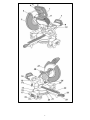 3
3
-
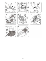 4
4
-
 5
5
-
 6
6
-
 7
7
-
 8
8
-
 9
9
-
 10
10
-
 11
11
-
 12
12
-
 13
13
-
 14
14
-
 15
15
-
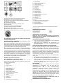 16
16
-
 17
17
-
 18
18
-
 19
19
-
 20
20
-
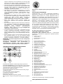 21
21
-
 22
22
-
 23
23
-
 24
24
-
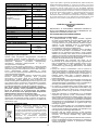 25
25
-
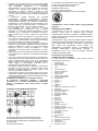 26
26
-
 27
27
-
 28
28
-
 29
29
-
 30
30
-
 31
31
-
 32
32
-
 33
33
-
 34
34
-
 35
35
-
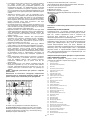 36
36
-
 37
37
-
 38
38
-
 39
39
-
 40
40
-
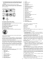 41
41
-
 42
42
-
 43
43
-
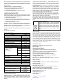 44
44
-
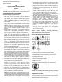 45
45
-
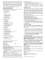 46
46
-
 47
47
-
 48
48
-
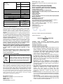 49
49
-
 50
50
-
 51
51
-
 52
52
-
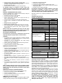 53
53
-
 54
54
-
 55
55
-
 56
56
-
 57
57
-
 58
58
-
 59
59
-
 60
60
-
 61
61
-
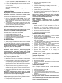 62
62
-
 63
63
-
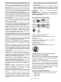 64
64
-
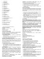 65
65
-
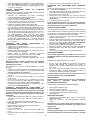 66
66
-
 67
67
-
 68
68
-
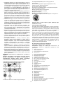 69
69
-
 70
70
-
 71
71
-
 72
72
-
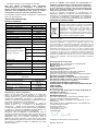 73
73
-
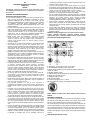 74
74
-
 75
75
-
 76
76
-
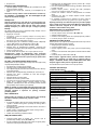 77
77
-
 78
78
-
 79
79
-
 80
80
-
 81
81
-
 82
82
-
 83
83
-
 84
84
-
 85
85
-
 86
86
-
 87
87
-
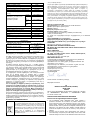 88
88
-
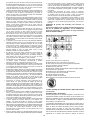 89
89
-
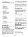 90
90
-
 91
91
-
 92
92
-
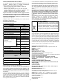 93
93
-
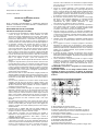 94
94
-
 95
95
-
 96
96
-
 97
97
-
 98
98
-
 99
99
-
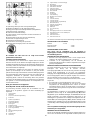 100
100
-
 101
101
-
 102
102
-
 103
103
-
 104
104
-
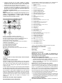 105
105
-
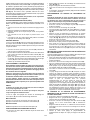 106
106
-
 107
107
-
 108
108
-
 109
109
-
 110
110


Graphite 59G812 Manual de utilizare
- Categorie
- Accesorii mixer / robot de bucătărie
- Tip
- Manual de utilizare
în alte limbi
- slovenčina: Graphite 59G812 Používateľská príručka
- eesti: Graphite 59G812 Kasutusjuhend
