Yamaha AX-397 Manualul proprietarului
- Categorie
- CD playere
- Tip
- Manualul proprietarului
Acest manual este potrivit și pentru

YAMAHA ELECTRONICS CORPORATION, USA
6660 ORANGETHORPE AVE., BUENA PARK, CALIF. 90620, U.S.A.
YAMAHA CANADA MUSIC LTD.
135 MILNER AVE., SCARBOROUGH, ONTARIO M1S 3R1, CANADA
YAMAHA ELECTRONIK EUROPA G.m.b.H.
SIEMENSSTR. 22-34, 25462 RELLINGEN BEI HAMBURG, GERMANY
YAMAHA ELECTRONIQUE FRANCE S.A.
RUE AMBROISE CROIZAT BP70 CROISSY-BEAUBOURG 77312 MARNE-LA-VALLEE CEDEX02, FRANCE
YAMAHA ELECTRONICS (UK) LTD.
YAMAHA HOUSE, 200 RICKMANSWORTH ROAD WATFORD, HERTS WD18 7GQ, ENGLAND
YAMAHA SCANDINAVIA A.B.
J A WETTERGRENS GATA 1, BOX 30053, 400 43 VÄSTRA FRÖLUNDA, SWEDEN
YAMAHA MUSIC AUSTRALIA PTY, LTD.
17-33 MARKET ST., SOUTH MELBOURNE, 3205 VIC., AUSTRALIA
©
2005 All rights reserved.
AX-497/AX-397
Printed in Malaysia WG02780
AX-497/AX-397
Stereo Amplifier
Amplificateur Stéréo
OWNER’S MANUAL
MODE D’EMPLOI
BEDIENUNGSANLEITUNG
BRUKSANVISNING
MANUALE DI ISTRUZIONI
MANUAL DE INSTRUCCIONES
E
AX-497_397_E-cv.fm Page 1 Tuesday, August 30, 2005 5:06 PM

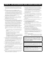
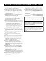
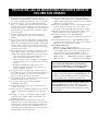
CAUTION: READ THIS BEFORE OPERATING YOUR UNIT.
1 To assure the finest performance, please read this manual
carefully. Keep it in a safe place for future reference.
2 Install this sound system in a well ventilated, cool, dry, clean
place – away from direct sunlight, heat sources, vibration,
dust, moisture, and/or cold. Allow ventilation space of at least
30 cm on the top, 20 cm on the left and right, and 20 cm on
the back of this unit.
3 Locate this unit away from other electrical appliances, motors,
or transformers to avoid humming sounds.
4 Do not expose this unit to sudden temperature changes from
cold to hot, and do not locate this unit in an environment with
high humidity (i.e. a room with a humidifier) to prevent
condensation inside this unit, which may cause an electrical
shock, fire, damage to this unit, and/or personal injury.
5 Avoid installing this unit where foreign objects may fall onto
this unit and/or this unit may be exposed to liquid dripping or
splashing. On the top of this unit, do not place:
– Other components, as they may cause damage and/or
discoloration on the surface of this unit.
– Burning objects (i.e. candles), as they may cause fire,
damage to this unit, and/or personal injury.
– Containers with liquid in them, as they may fall and liquid
may cause electrical shock to the user and/or damage to
this unit.
6 Do not cover this unit with a newspaper, tablecloth, curtain,
etc. in order not to obstruct heat radiation. If the temperature
inside this unit rises, it may cause fire, damage to this unit,
and/or personal injury.
7 Do not plug in this unit to a wall outlet until all connections
are complete.
8 Do not operate this unit upside-down. It may overheat,
possibly causing damage.
9 Do not use force on switches, knobs and/or cords.
10 When disconnecting the power cable from the wall outlet,
grasp the plug; do not pull the cable.
11 Do not clean this unit with chemical solvents; this might
damage the finish. Use a clean, dry cloth.
12 Only voltage specified on this unit must be used. Using this
unit with a higher voltage than specified is dangerous and may
cause fire, damage to this unit, and/or personal injury.
YAMAHA will not be held responsible for any damage
resulting from use of this unit with a voltage other than
specified.
13 Do not attempt to modify or fix this unit. Contact qualified
YAMAHA service personnel when any service is needed. The
cabinet should never be opened for any reasons.
14 When not planning to use this unit for long periods of time
(i.e. vacation), disconnect the AC power plug from the wall
outlet.
15 Install this unit near the AC outlet and where the AC power
plug can be reached easily.
16 Be sure to read the “TROUBLESHOOTING” section on
common operating errors before concluding that this unit is
faulty.
17 Before moving this unit, press STANDBY/ON to set this unit
in the standby mode, and disconnect the AC power plug from
the wall outlet.
18 VOLTAGE SELECTOR (Asia and General models only)
The VOLTAGE SELECTOR on the rear panel of this unit
must be set for your local main voltage BEFORE plugging
into the AC main supply. Voltages are:
General model.............AC 110/120/220/230–240 V, 50/60 Hz
Asia model ................................AC 220/230–240 V, 50/60 Hz
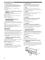
■ For U.K. customers
If the socket outlets in the home are not suitable for the
plug supplied with this appliance, it should be cut off and
an appropriate 3 pin plug fitted. For details, refer to the
instructions described below.
The plug severed from the mains lead must be destroyed, as a
plug with bared flexible cord is hazardous if engaged in a live
socket outlet.
■ Special Instructions for U.K. Model
CAUTION: READ THIS BEFORE OPERATING YOUR UNIT.
WARNING
TO REDUCE THE RISK OF FIRE OR ELECTRIC
SHOCK, DO NOT EXPOSE THIS UNIT TO RAIN
OR MOISTURE.
As long as this unit is connected to the AC wall outlet,
it is not disconnected from the AC power source even
if you turn off this unit by POWER or set it to the
standby mode by STANDBY/ON.
This unit enters the standby mode when you press
POWER inward to the ON position and then press
STANDBY/ON. In this state, this unit is designed to
consume a very small quantity of power.
Note
IMPORTANT
THE WIRES IN MAINS LEAD ARE COLOURED IN
ACCORDANCE WITH THE FOLLOWING CODE:
Blue: NEUTRAL
Brown: LIVE
As the colours of the wires in the mains lead of this
apparatus may not correspond with the coloured
markings identifying the terminals in your plug,
proceed as follows:
The wire which is coloured BLUE must be connected
to the terminal which is marked with the letter N or
coloured BLACK. The wire which is coloured
BROWN must be connected to the terminal which is
marked with the letter L or coloured RED.
Making sure that neither core is connected to the earth
terminal of the three pin plug.

1
PREPARATIONINTRODUCTION
OPERATION
ADDITIONAL
INFORMATION
English
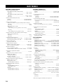
FEATURES............................................................. 2
SUPPLIED ACCESSORIES ................................. 2
CONTROLS AND FUNCTIONS ......................... 3
Front panel ................................................................. 3
Remote control........................................................... 5
Installing batteries in the remote control ................... 6
Using the remote control ........................................... 6
Rear panel .................................................................. 7
CONNECTIONS .................................................... 8
Connecting speakers and other components.............. 8
Connecting the power supply cord .......................... 10
PLAYING AND RECORDING .......................... 11
Playing a source....................................................... 11
Adjusting the tonal quality....................................... 13
Recording a source to a tape or an MD ................... 14
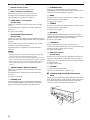
TROUBLESHOOTING....................................... 16
SPECIFICATIONS .............................................. 18
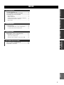
CONTENTS
INTRODUCTION
PREPARATION
OPERATION
ADDITIONAL INFORMATION

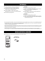
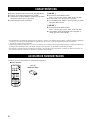
FEATURES
2
◆ Highly dynamic power, low impedance drive
capability
◆ Continuously variable loudness control
◆ CD/DVD DIRECT AMP switch used to reproduce the
purest CD and DVD sound
◆ Remote control capability
[ AX-497 ]
◆ Minimum RMS output power
85 W + 85 W (8 Ω), 0.019% THD, 20 Hz to 20 kHz
◆ REC OUT selector independent of input source
selection
◆ PURE DIRECT switch used to reproduce the purest
source sound
[ AX-397 ]
◆ Minimum RMS output power
60 W + 60 W (8 Ω), 0.019% THD, 20 Hz to 20 kHz
◆ TAPE MONITOR switch used to monitor the sound
being recorded
• This document is the owner’s manual for both AX-497 and AX-397. Model names are given where the details of functions are unique
to each model. Illustrations for AX-497 are mainly used for explanations.
• y indicates a tip for your operation.
• Some operations can be performed by using either the buttons on the main unit or on the remote control. In cases when the button
names differ between the main unit and the remote control, the names of the buttons on the remote control are given in parentheses.
• This manual is printed prior to production. Design and specifications are subject to change in part as a result of improvements, etc. In
case of differences between the manual and the product, the product has priority.
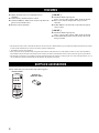
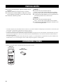
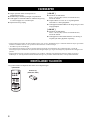
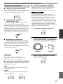
Please check that you received all of the following parts.
FEATURES
SUPPLIED ACCESSORIES
CD/DVD PHONO TUNER
POWER
STANDBY
MD
TAPE AUX
+
–
u
d
DISPLAY
A/B
REC
DISC
DIR A
p
DIR B
A/B/C/D/E
PRESET
VOLUME
TAPECD
w
e
f
b
s
a
DISPLAY
Remote control
Batteries (2)
(AAA, R03, UM-4)

CONTROLS AND FUNCTIONS
3
INTRODUCTION
English
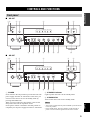
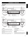
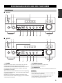
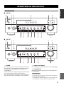
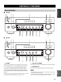
■ AX-497
■ AX-397
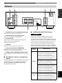
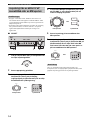
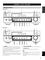
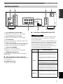
1 POWER
Press inward to the ON position to provide this unit with
power supply from the AC wall outlet. In this state, you
can turn on this unit or set it to the standby mode by
pressing STANDBY/ON.
When you turn on this unit, there will be a few second
delay before this unit can reproduce sound.
Press again to release it outward to the
OFF
position to
completely cut off power supply from the AC wall outlet.
2 STANDBY indicator
Lights up when this unit is in the standby mode.
3 STANDBY/ON
Turns on this unit or sets it to the standby mode.
• This switch is operational only when POWER is pressed inward
to the ON position.
• In the standby mode, this unit consumes a small amount of
power to receive infrared-signals from the remote control.
CONTROLS AND FUNCTIONS
Front panel
STANDBY
/ON
STANDBY
INPUT
PHONES SPEAKERS BASS
A
POWER
ON
OFF
ON
OFF
AUX MD TAP E CD/DVD TUNER PHONO PURE DIRECT CD/DVD DIRECT AMP
B
5
1
4
2
3
5
1
4
2
3
+
–
TREBLE
5
1
4
2
3
5
1
4
2
3
+
–
BALANCE
5
1
4
2
3
5
1
4
2
3
TUNER
PHONO
TAP E
MD
AUX
R
L
LOUDNESS REC OUT
VOLU ME
7
–
30dB
FLAT CD/DVD
10
9
5
6
1
4
2
3
0
12
12
2
8
4
∞
20
20
60
60
26
26
40
40
16
16
-dB
-dB
8
DISPLAY
41
3
25
FD
CBA90 E
8
6
STANDBY
/ON
STANDBY
INPUT
PHONES SPEAKERS BASS
5
1
4
2
3
5
1
4
2
3
A
POWER
ON
OFF
ON
OFF
AUX MD TAP E CD/DVD TUNER PHONO TAPE MONITOR CD/DVD DIRECT AMP
B
+
–
TREBLE
5
1
4
2
3
5
1
4
2
3
+
–
BALANCE
5
1
4
2
3
5
1
4
2
3
R
L
LOUDNESS
VOLU ME
7
–
30dB
FLAT
10
9
5
6
1
48
2
3
DISPLAY
41
3
25
D
CBA90
8
7
0
12
12
2
8
4
∞
20
20
60
60
26
26
40
40
16
16
-dB
-dB
F
Notes

CONTROLS AND FUNCTIONS
4
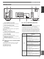
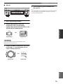
4 Remote control sensor
Receives signals from the remote control.
5 INPUT selector and indicators
Selects the input source you want to listen to.
The input source indicators light up when the
corresponding input sources are selected.
6 PURE DIRECT and indicator
(AX-497 only)
Allows you to listen to a source in the purest possible
sound.
The indicator above it lights up when this function is
turned on.
See page 13 for details.
7 TAPE MONITOR and indicator
(AX-397 only)
Allows you to listen to the sound played back on the tape
deck connected to the TAPE terminals on the rear panel of
this unit.
When the tape deck is used for recording, you can also
monitor the sound being recorded.
The indicator above it lights up when this function is
turned on.
• When this function is on (the indicator lights up), TAPE (tape
deck) cannot be selected with the INPUT selector.
• To listen to the source selected with the INPUT selector, press
again to turn off the function (the indicator turns off as a result).
• When TAPE (tape deck) is selected with the INPUT selector,
this function will not turn on even if TAPE MONITOR is
pressed.
8 CD/DVD DIRECT AMP and indicator
Allows you to listen to a CD or a DVD source in the
purest sound.
The indicator above it lights up when this function is
turned on.
See page 13 for details.
9 PHONES jack
Outputs audio for private listening with headphones.
Press both SPEAKERS A and B switches on the front
panel to release them outward to the OFF position.
0 SPEAKERS A/B
Turns on or off the speaker set connected to the
SPEAKERS A and/or B terminals on the rear panel each
time the corresponding button is pressed.
A BASS
Increases or decreases the low frequency response. The 0
position produces a flat response.
See page 13 for details.
B TREBLE
Increases or decreases the high frequency response. The 0
position produces a flat response.
See page 13 for details.
C BALANCE
Adjusts the sound output balance of the left and right
speakers to compensate for sound imbalances caused by
speaker locations or listening room conditions.
See page 13 for details.
D LOUDNESS
Retains a full tonal range at any volume level to
compensates for the human ears’ loss of sensitivity to high
and low-frequency ranges at low volume.
See page 13 for details.
E REC OUT selector
(AX-497 only)
Selects a source for recording to the MD recorder or the
tape deck independently of the INPUT selector setting,
allowing you to record the selected source while listening
to another source.
See page 14 for details.
F VOLUME
Controls the sound output level.
This does not affect the OUT (REC) level.
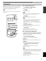
■ Opening and closing the front panel
door
When you want to use the controls behind the front panel
door, open the door by gently pressing on the lower part of
the panel. Keep the door closed when not using these
controls to protect the controls from dust, etc.
Notes

CONTROLS AND FUNCTIONS
5
INTRODUCTION
English
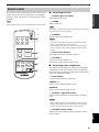
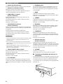
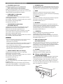
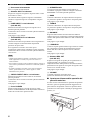
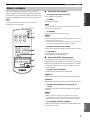
This section describes the function of each control on the
remote control used to control this unit or a YAMAHA
CD player, tuner, tape deck, etc. with the remote control
capability.
Some components may not be controlled by this remote control.
■ Controlling this unit
1 Infrared signal transmitter
Sends signals to this unit.
2 POWER
Turns on this unit.
This button is operational only when POWER on the front panel
is pressed inward to the ON position.
3 STANDBY
Sets this unit to the standby mode.
• This button is operational only when POWER on the front
panel is pressed inward to the ON position.
• In the standby mode, this unit consumes a small amount of
power in order to receive infrared-signals from the remote
control.
4 Input selector buttons
Select the input source you want to listen to.
5 VOLUME +/–
Controls the sound output level.
This does not affect the OUT (REC) level.
■ Controlling other components
The functions of the buttons to control other YAMAHA
components are the same as those of the corresponding
buttons on those components. Refer to those components’
instruction manuals for details.
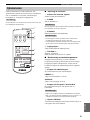
6 Tuner buttons
Control various functions of the tuner.
PRESET +/–
Selects a preset station number (1 to 8).
A/B/C/D/E
Selects a preset station group (A to E).
7 CD player / tape deck buttons
Control various functions of the CD player or the tape
deck.
• DIR B and A/B apply only to the double cassette tape deck.
• Pressing DIR A will reverse the tape direction on the single
cassette tape deck with the automatic reverse function.
8 CD/TAPE selector switch
Switches to control either CD player functions or tape
deck functions.
Remote control
Note
CD/DVD PHONO TUNER
POWER
STANDBY
MD
TAPE AUX
+
–
u
d
DISPLAY
A/B
REC
DISC
DIR A
p
DIR B
A/B/C/D/E
PRESET
VOLUME
TAPECD
w
e
f
b
s
a
DISPLAY
1
2
4
7
6
8
3
5
Note
Notes
Notes

CONTROLS AND FUNCTIONS
6
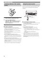
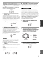
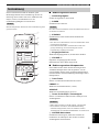
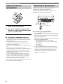
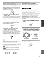
1 Open the battery compartment cover.
2 Insert two supplied batteries
(AAA, R03, UM-4) according to the polarity
markings (+ and –) on the inside of the
battery compartment.
3 Close the cover back.
■ Notes on batteries
• Change all of the batteries if you notice the following
conditions; the operation range of the remote control decreases,
the indicator does not flash or its light becomes dim.
• Use AAA, R03, UM-4 batteries.
• Make sure that the polarities are correct. See the illustration
inside the battery compartment.
• Remove the batteries if the remote control is not used for an
extended period of time.
• Do not use old batteries together with new ones.
• Do not use different types of batteries (such as alkaline and
manganese batteries) together. Read the packaging carefully as
these different types of batteries may have the same shape and
color.
• We strongly recommend using alkaline batteries.
• If the batteries have leaked, dispose of them immediately. Avoid
touching the leaked material or letting it come into contact with
clothing, etc. Clean the battery compartment thoroughly before
installing new batteries.
• Do not throw away batteries with general house waste; dispose
of them correctly in accordance with your local regulations.
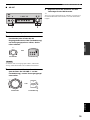
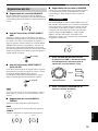
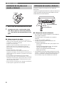
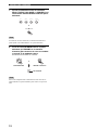
The remote control transmits a directional infrared beam.
Be sure to aim the remote control directly at the remote
control sensor on the front panel of this unit during
operation.
■ Handling the remote control
• The area between the remote control and this unit must
be clear of large obstacles.
• Do not spill water or other liquids on the remote
control.
• Do not drop the remote control.
• Do not leave or store the remote control in the
following types of conditions:
– places of high humidity, such as near a bath
– places of high temperature, such as near a heater or
a stove
– places of extremely low temperatures
– dusty places
• Do not expose the remote control sensor to strong
lighting, in particular, an inverter type fluorescent
lamp; otherwise, the remote control may not work
properly. If necessary, position this unit away from
direct lighting.
Installing batteries in the remote
control
1
3
2
Using the remote control
STANDBY
/ON
STANDBY
INPUT
PHONES SPEAKERS BASS
5
1
4
2
3
5
1
4
2
3
A
POWER
ON
OFF
ON
OFF
AUX MD TAPE CD/DVD TUNER PHONO PURE DIRECT CD/DVD DIRECT AMP
B
+
–
TREBLE
5
1
4
2
3
5
1
4
2
3
+
–
BALANCE
5
1
4
2
3
5
1
4
2
3
TUNER
PHONO
TAPE
MD
AUX
R
L
LOUDNESS REC OUT
VOLUME
7
–
30dB
FLAT CD/DVD
10
9
5
6
1
4
2
3
8
30 30
0
12
12
2
8
4
∞
20
20
60
60
26
26
40
40
16
16
-dB
-dB
CD/DVD PHONO TUNER
POWER
STANDBY
MD
TAPE AUX
+
–
MUTE
A/B/C/D/E
VOLUME
TAPECD
u
d
PRESET
DISPLAY
A/B
REC
DISC
DIR A
p
DIR B
w
e
f
b
s
a
DISPLAY
Approximately 6 m

CONTROLS AND FUNCTIONS
7
INTRODUCTION
English
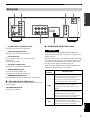
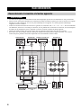
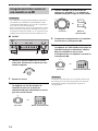
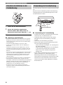
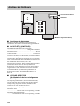
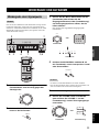
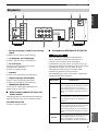
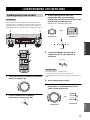
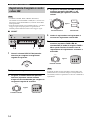
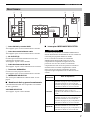
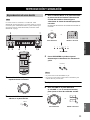
1 PHONO jacks and GND terminal
See page 8 for connection information.
2 Audio input/output jacks
See page 8 for connection information.
3 AC OUTLET(S)
Use to supply power to your other audio/video
components.
See page 10 for details.
4 AC power supply cord
See page 10 for connection information.
5 SPEAKERS terminals
Connect one or two speaker sets.
See page 8 for connection information.
6 IMPEDANCE SELECTOR
See “IMPEDANCE SELECTOR switch” on this page.
■ Asia and General models only
VOLTAGE SELECTOR is only applicable to the Asia and
General models.
VOLTAGE SELECTOR
See page 10 for details.
■ IMPEDANCE SELECTOR switch
Do not change the IMPEDANCE SELECTOR switch
while the power of this unit is turned on, as doing so may
damage the unit.
If this unit fails to turn on, the IMPEDANCE SELECTOR
switch may not be fully slid to either position. If this is the
case, slide the switch all the way to either position when
this unit’s power supply is completely cut off.
Select the switch position (left or right) according to the
impedance of the speakers in your system.
Rear panel
AC OUTLETS
IMPEDANCE SELECTOR
SPEAKERS
TUNER
TAPE
IN
(PLAY)
OUT
(REC)
MD
AUX
GND
PHONO
CD/DVD
IN
(PLAY)
OUT
(REC)
SWITCHED
100W MAX. TOTAL
++
A
B
––
A OR B: 4ΩMIN / SPEAKER
A+B: 8ΩMIN / SPEAKER
A OR B: 6ΩMIN / SPEAKER
5
12 3 4
6
(U.S.A. model)
Switch
position
Impedance level
Right
Asia model
• If you use one set (A or B), the impedance of
each speaker must be 8
Ω or higher.
• If you use two sets (A and B), the impedance
of each speaker must be 16
Ω or higher.
Canada model
• You can use one set (A or B), and the
impedance of each speaker must be 6
Ω or
higher.
Other models
• If you use one set (A or B), the impedance of
each speaker must be 6
Ω or higher.
• If you use two sets (A and B), the impedance
of each speaker must be 12
Ω or higher.
Left
• If you use one set (A or B), the impedance of
each speaker must be 4
Ω or higher.
• If you use two sets (A and B), the impedance
of each speaker must be 8
Ω or higher.
CAUTION

CONNECTIONS
8
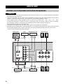
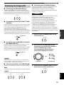
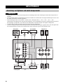
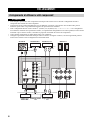
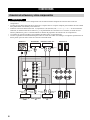
• Do not connect this unit or other components to the main power until all connections between components are
complete.
• Do not let the bare speaker wires touch each other or do not let them touch any metal part of this unit. This could
damage this unit and/or the speakers.
• All connections must be correct: L (left) to L, R (right) to R, “+” to “+” and “–” to “–”. If the connections are faulty,
no sound will be heard from the speakers, and if the polarity of the speaker connections is incorrect, the sound will be
unnatural and lack bass. Also, refer to the owner’s manual for each of your components.
• Use RCA type pin plug cables for audio/video units except speakers.
• Connect your turntable to the GND terminal to reduce noise in the signal. However, you may hear less noise without
the connection to the GND terminal for some record players.
•
CONNECTIONS
Connecting speakers and other components
CAUTION
SPEAKERS
TUNER
TAPE
IN
(PLAY)
OUT
(REC)
MD
AUX
GND
PHONO
CD/DVD
IN
(PLAY)
OUT
(REC)
++
A
B
––
LR
R L
R L
L
R
LR
L
R
+– +–
+– +–
LR LR
Turntable Tuner
Audio in
Audio out
Tape deck, etc.
CD player or
DVD player
VCR, etc. MD recorder,
etc.
Audio out
Audio out
GND
Audio out Audio out Audio outAudio in
Speakers A
Speakers B

9
CONNECTIONS
PREPARATION
English
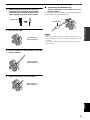
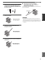
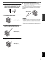
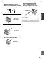
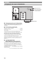
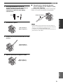
1 Remove approximately 10 mm (3/8 in) of
insulation from the end of each speaker
cable and twist the exposed wires of the
cable together to prevent short circuits.
2 Unscrew the knob.
3 Insert one bare wire into the hole in the side
of each terminal.
4 Tighten the knob to secure the wire.
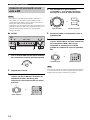
■ Connecting the banana plug
(With the exception of Asia, Korea, U.K. and
Europe models)
First, tighten the knob and then insert the banana plug into
the end of the corresponding terminal.
• One or two speaker sets can be connected to this unit. If you use
only one speaker set, connect it to either the SPEAKERS A or B
terminals.
• Use speakers with the specified impedance shown on the rear
panel of this unit.
10 mm (3/8 in)
Red: positive (+)
Black: negative (–)
Red: positive (+)
Black: negative (–)
Red: positive (+)
Black: negative (–)
Notes
Banana plug

10
CONNECTIONS
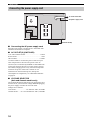
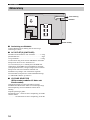
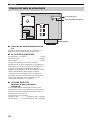
■ Connecting the AC power supply cord
Plug the power supply cord into the AC wall outlet after
all other connections are complete.
■ AC OUTLET(S) (SWITCHED)
U.K. and Australia models ..................................... 1 outlet
Korea model .............................................................. None
Other models ........................................................ 3 outlets
Use these outlets to connect the power cords from your
other components to this unit. The power to the AC
OUTLET(S) is controlled by POWER or STANDBY/ON
on the front panel of this unit (or on the remote control).
The outlet(s) supply power to any connected component
whenever the power of this unit is turned on. For
information on the maximum power (total power
consumption of components), see “SPECIFICATIONS”
on page 18.
■ VOLTAGE SELECTOR
(Asia and General models only)
The VOLTAGE SELECTOR on the rear panel of this unit
must be set for your local main voltage BEFORE plugging
the power supply cord into the AC wall outlet.
Voltages are as follows:
Asia model.......................... AC 220/230–240 V, 50/60 Hz
General model ...... AC 110/120/220/230–240 V, 50/60 Hz
Connecting the power supply cord
AC OUTLETS
VOLTAGE SELECTOR
IMPEDANCE SELECTOR
SWITCHED
100W MAX. TOTAL
A OR B: 4ΩMIN / SPEAKER
A+B: 8ΩMIN / SPEAKER
A OR B: 6ΩMIN / SPEAKER
A+B: 12ΩMIN / SPEAKER
(General model)
To an AC wall outlet
AC power supply cord

PLAYING AND RECORDING
11
English
OPERATION
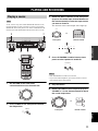
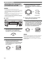
As for AX-397 only, if the TAPE MONITOR indicator on the
front panel lights up when you listen to a source, press TAPE
MONITOR on the front panel to turn off the TAPE MONITOR
function (the TAPE MONITOR indicator turns off as a result).
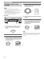
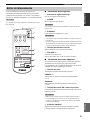
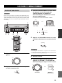
1 Set VOLUME on the front panel
counterclockwise to the extreme end.
2 Press POWER on the front panel inward to
the ON position.
3 Rotate the INPUT selector on the front panel
(or press one of the input selector buttons on
the remote control) to select the input source
you want to listen to.
The indicator of the selected input source lights up.
4 Press SPEAKERS A and/or B on the front
panel to select speakers A and/or B.
• Both SPEAKERS A and B can be selected.
• If you listen with headphones, press both switches to release
them outward to the OFF position.
5 Play the source.
6 Rotate VOLUME on the front panel (or press
VOLUME +/– on the remote control) to adjust
the sound output level.
PLAYING AND RECORDING
Playing a source
Note
0
12
12
2
8
4
∞
20
20
60
60
26
26
40
40
16
16
-dB
-dB
STANDBY
/ON
STANDBY
INPUT
PHONES SPEAKERS BASS
5
1
4
2
3
5
1
4
2
3
A
POWER
ON
OFF
ON
OFF
AUX MD TAPE CD/DVD TUNER PHONO PURE DIRECT CD/DVD DIRECT AMP
B
+
–
TREBLE
5
1
4
2
3
5
1
4
2
3
+
–
BALANCE
5
1
4
2
3
5
1
4
2
3
TUNER
PHONO
TAPE
MD
AUX
R
L
LOUDNESS REC OUT
VOLUME
7
–
30dB
FLAT CD/DVD
10
9
5
6
1
4
2
3
8
43
8
7
1,6
27
CD/DVD PHONO TUNER
POWER
STANDBY
MD
TAPE AU X
+
–
u
d
DISPLAY
A/B
REC
DISC
DIR A
p
DIR B
A/B/C/D/E
PRESET
VOLUME
TAPECD
w
e
f
b
s
a
DISPLAY
8
6
3
0
12
12
2
8
4
∞
20
20
60
60
26
26
40
40
16
16
-dB
-dB
VOLUME
POWER
ON
OFF
Notes
INPUT
CD/DVD PHONO TUNER
POWER
STANDBY
MD
TAPE AU X
AUX MD TAP E CD/DVD TUNER PHONO
Front panel Remote control
or
Lights up
SPEAKERS
A
ON OFF
B
0
12
12
2
8
4
∞
20
20
60
60
26
26
40
40
16
16
-dB
-dB
VOLUME
+
–
VOLUME
Remote control
Front panel
or

12
PLAYING AND RECORDING
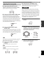
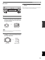
7 Adjust the tonal quality by using the BASS,
TREBLE, BALANCE and LOUDNESS controls
or the CD/DVD DIRECT AMP switch on the
front panel.
As for AX-497 only, you can also adjust the tonal quality by
using PURE DIRECT on the front panel.
8 Press STANDBY/ON on the front panel again
(or STANDBY on the remote control) to finish
using this unit and set it to the standby
mode.
The STANDBY indicator lights up.
To completely cut off power supply from the AC wall outlet,
press POWER on the front panel to release it outward to the OFF
position.
Note
Note
BASS
5
1
4
2
3
5
1
4
2
3
+
–
TREBLE
5
1
4
2
3
5
1
4
2
3
+
–
BALANCE
5
1
4
2
3
5
1
4
2
3
R
L
LOUDNESS
7
–
30dB
FLAT
10
9
5
6
1
4
2
3
8
CD/DVD DIRECT AMP
or
STANDBY
/ON
STANDBY
STANDBY
Remote control
Front panel
or
Lights up

13
PLAYING AND RECORDING
OPERATION
English
■ Adjusting the BALANCE control
Adjusts the sound output balance of the left and right
speakers to compensate for sound imbalance caused by
speaker locations or listening room conditions.
■ Using the CD/DVD DIRECT AMP switch
Routes input signals from your CD or DVD player
directly to the specially built-in amplifier for the CD or
DVD player. As a result, the input signals bypass the
INPUT selector and the BASS, TREBLE, BALANCE and
LOUDNESS controls (and the TAPE MONITOR switch
for AX-397 only) and then sent to the power amplifier,
thus eliminating any alterations to the CD or DVD signals
and creating the purest possible sound.
■ Using the PURE DIRECT switch
(AX-497 only)
Routes input signals from your audio sources. As a result,
the input signals bypass the BASS, TREBLE, BALANCE
and LOUDNESS controls, thus eliminating any alterations
to the audio signals and creating the purest possible sound.
As for AX-497 only, if both the CD/DVD DIRECT AMP and the
PURE DIRECT switches are turned on, only the CD/DVD
DIRECT AMP switch will function.
■ Adjusting the BASS and TREBLE
controls
Adjusts the high and low frequency response.
BASS
Increases or decreases the low frequency response.
TREBLE
Increases or decreases the high frequency response.
■ Adjusting the LOUDNESS control
Retains a full tonal range at any volume level, thus
compensating for the human ears’ loss of sensitivity to
high and low-frequency ranges at low volume.
If the CD/DVD DIRECT AMP switch (or the PURE
DIRECT switch for AX-497 only) is turned on with the
LOUDNESS control set at a certain level, the input signals
bypass the LOUDNESS control, resulting in a sudden
increase in the sound output level. To prevent your ears or
the speakers from being undesirably damaged, be sure to
press the CD/DVD DIRECT AMP switch (or the PURE
DIRECT switch for AX-497 only) AFTER lowering the
sound output level or AFTER checking that the
LOUDNESS control is properly set.
1 Set the LOUDNESS control to the FLAT
position.
2 Rotate VOLUME on the front panel (or press
VOLUME +/– on the remote control) to set the
sound output level to the loudest listening
level that you would listen to.
3 Rotate the LOUDNESS control until the
desired volume is obtained.
Adjusting the tonal quality
Note
BALANCE
5
1
4
2
3
5
1
4
2
3
R
L
CD/DVD DIRECT AMP
Lights up
PURE DIRECT
Lights up
BASS
5
1
4
2
3
5
1
4
2
3
+
–
TREBLE
5
1
4
2
3
5
1
4
2
3
+
–
CAUTION
LOUDNESS
7
–
30dB
FLAT
10
9
5
6
1
4
2
3
8
0
12
12
2
8
4
∞
20
20
60
60
26
26
40
40
16
16
-dB
-dB
VOLUME
+
–
VOLUME
Remote control
Front panel
or
LOUDNESS
7
–
30dB
FLAT
10
9
5
6
1
4
2
3
8

14
PLAYING AND RECORDING
• The VOLUME, BASS, TREBLE, BALANCE and
LOUDNESS controls and the CD/DVD DIRECT AMP switch
(and the PURE DIRECT switch for AX-497 only) have no
effect on the source being recorded.
• Check the copyright laws in your country to record from
records, CDs, radio, etc. Recording copyright-protected
material may infringe on copyright laws.
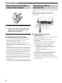
■ AX-497
1 Rotate the REC OUT selector on the front
panel to select the source you want to
record.
2 Play the source.
3 Rotate the INPUT selector on the front panel
(or press one of the input selector buttons on
the remote control) to select the input source
you want to listen to.
4 Rotate VOLUME on the front panel (or press
VOLUME +/– on the remote control) to adjust
the sound output level.
5 Begin recording on the tape deck or the MD
recorder.
6 Rotate the INPUT selector on the front panel
(or press TAPE or MD on the remote control)
to select TAPE or MD and then monitor the
sound being recorded on the tape deck or
the MD recorder.
Selecting another source with the INPUT selector on the front
panel (or the corresponding input selector button on the remote
control) while recording is in progress will not affect the
recording.
Recording a source to a tape
or an MD
Notes
0
12
12
2
8
4
∞
20
20
60
60
26
26
40
40
16
16
-dB
-dB
STANDBY
/ON
STANDBY
INPUT
PHONES SPEAKERS BASS
5
1
4
2
3
5
1
4
2
3
A
POWER
ON
OFF
ON
OFF
AUX MD TAPE CD/DVD TUNER PHONO PURE DIRECT CD/DVD DIRECT AMP
B
+
–
TREBLE
5
1
4
2
3
5
1
4
2
3
+
–
BALANCE
5
1
4
2
3
5
1
4
2
3
TUNER
PHONO
TAPE
MD
AUX
R
L
LOUDNESS REC OUT
VOLUME
7
–
30dB
FLAT CD/DVD
10
9
5
6
1
4
2
3
8
3,6
41
TUNER
PHONO
TAPE
MD
AUX
REC OUT
CD/DVD
INPUT
CD/DVD PHONO TUNER
POWER
STANDBY
MD
TAPE AU X
Remote control
Front panel
or
Note
0
12
12
2
8
4
∞
20
20
60
60
26
26
40
40
16
16
-dB
-dB
VOLUME
+
–
VOLUME
Remote control
Front panel
or
CD/DVD PHONO TUNER
POWER
STANDBY
MD
TAPE AU X
Remote control
Front panel
or
INPUT

15
PLAYING AND RECORDING
OPERATION
English
■ AX-397
1 Play the source.
2 Rotate the INPUT selector on the front panel
(or press one of the input selector buttons on
the remote control) to select the input source
you want to listen to.
You cannot select any input source while the TAPE MONITOR
indicator on the front panel lights up.
3 Rotate VOLUME on the front panel (or press
VOLUME +/– on the remote control) to adjust
the sound output level.
4 Begin recording on the tape deck or the MD
recorder.
y
If the 3-head tape deck is used for recording, you can monitor the
sound of recording by pressing TAPE MONITOR.
Note
0
12
12
2
8
4
∞
20
20
60
60
26
26
40
40
16
16
-dB
-dB
STANDBY
/ON
STANDBY
INPUT
PHONES SPEAKERS BASS
5
1
4
2
3
5
1
4
2
3
A
POWER
ON
OFF
ON
OFF
AUX MD TAPE CD/DVD TUNER PHONO TAPE MON ITO R CD/DVD DIRECT AMP
B
+
–
TREBLE
5
1
4
2
3
5
1
4
2
3
+
–
BALANCE
5
1
4
2
3
5
1
4
2
3
R
L
LOUDNESS
VOLUME
7
–
30dB
FLAT
10
9
5
6
1
4
2
3
8
2
3
Remote control
Front panel
or
INPUT
CD/DVD PHONO TUNER
POWER
STANDBY
MD
TAPE AU X
0
12
12
2
8
4
∞
20
20
60
60
26
26
40
40
16
16
-dB
-dB
VOLUME
+
–
VOLUME
Remote control
Front panel
or

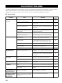
TROUBLESHOOTING
16
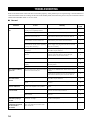
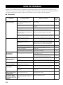
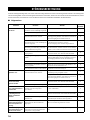
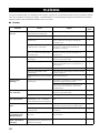
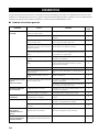
Refer to the chart below if this unit does not function properly. If the problem you are experiencing is not listed below or
if the instructions below do not help, set this unit to the standby mode, disconnect the power cord, and contact the nearest
authorized YAMAHA dealer or service center.
■ General
TROUBLESHOOTING
Problem Cause Remedy
Refer to
page
This unit fails to turn
on.
The power supply cord is not connected or
the plug is not completely inserted.
Connect the power supply cord firmly.
—
The impedance setting is incorrect. Set the impedance to match your speakers.
7
The protection circuitry has been activated
because of a short circuit, etc.
Check that the speaker wires are not touching each
other and then turn the power of this unit back on.
8
The IMPEDANCE SELECTOR switch on
the rear panel is not set to either end.
Set the IMPEDANCE SELECTOR switch to either
end when the power of this unit is turned off.
7
This unit has been exposed to a strong
external electric shock (such as lightning
or strong static electricity).
Set this unit to the standby mode, disconnect the
power supply cord, plug it back in after 30 seconds,
then use it normally.
—
No sound Incorrect input or output cable
connections.
Connect the cables properly. If the problem persists,
the cables may be defective.
8
No appropriate input source has been
selected.
Select an appropriate input source with the INPUT
selector on the front panel (or one of the input
selector buttons on the remote control).
11
The TAPE MONITOR function is turned
on.
Turn off the TAPE MONITOR function.
4
The SPEAKERS A/B switches are not set
properly.
Set the corresponding SPEAKERS A or B switch to
the ON position.
11
Speaker connections are not secure. Secure the connections.
8
The sound suddenly
goes off.
The protection circuitry has been activated
because of a short circuit, etc.
Check that the IMPEDANCE SELECTOR setting is
correct.
7
Check that the speaker wires are not touching each
other and then turn the power of this unit back on.
8
Only the speaker on
one side can be
heard.
Incorrect cable connections. Connect the cables properly. If the problem persists,
the cables may be defective.
8
Incorrect setting for the BALANCE
control.
Set the BALANCE control to the appropriate
position.
13
There is a lack of bass
and no ambience.
The + and – wires are connected in
reverse at the amplifier or the speakers.
Connect the speaker wires to the correct + and –
phase.
8
A “humming” sound
can be heard.
Incorrect cable connections. Connect the audio plugs firmly. If the problem
persists, the cables may be defective.
8
No connection from the turntable to the
GND terminal.
Make the GND connection between the turntable and
this unit.
8
The volume level is
low while playing a
record.
The record is being played on a turntable
with an MC cartridge.
The turntable should be connected to this unit through
the MC head amplifier.
—
The volume level
cannot be increased,
or the sound is
distorted.
The component connected to the TAPE
OUT or the MD OUT terminals of this
unit is turned off.
Turn on the power of the component.
—

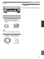
17
TROUBLESHOOTING
ADDITIONAL
INFORMATION
English
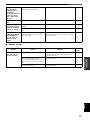
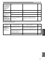
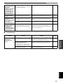
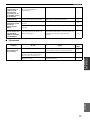
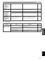
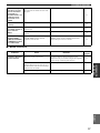
■ Remote control
The sound is
degraded when
listening with the
headphones
connected to the CD
player or the tape
deck connected to
this unit.
The power of this unit is turned off, or this
unit is set to the standby mode.
Turn on the power of this unit.
11
The sound level is
low.
The LOUDNESS control is functioning. Set the LOUDNESS control to the FLAT position.
13
The input source
cannot be changed
although the INPUT
selector is rotated.
The CD/DVD DIRECT AMP switch is
turned on.
Turn off the CD/DVD DIRECT AMP switch.
13
The TAPE MONITOR function is turned
on.
Turn off the TAPE MONITOR function.
4
Using the BASS,
TREBLE, BALANCE
and LOUDNESS
controls does not
affect the tonal
quality.
The CD/DVD DIRECT AMP switch (or
the PURE DIRECT switch for AX-497
only) is turned on.
The CD/DVD DIRECT AMP switch (or the PURE
DIRECT switch for AX-497 only) must be turned off
to use those controls.
13
Problem Cause Remedy
Refer to
page
The remote control
does not work nor
function properly.
Wrong distance or angle. The remote control will function within a maximum
range of 6 m and no more than 30 degrees off-axis
from the front panel.
6
Direct sunlight or lighting (from an
inverter type of fluorescent lamp, etc.) is
striking the remote control sensor of this
unit.
Reposition this unit.
—
The batteries are weak. Replace all batteries.
6

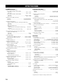
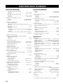
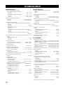
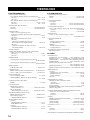
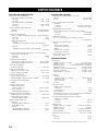
SPECIFICATIONS
18
POWER SECTION
• Minimum RMS Output Power
(8 Ω , 20 Hz to 20 kHz, 0.019% THD)
[AX-497] .............................................................. 85 W + 85 W
[AX-397] .............................................................. 60 W + 60 W
(6 Ω , 20 Hz to 20 kHz, 0.038% THD)
[AX-497] .......................................................... 100 W + 100 W
[AX-397] .............................................................. 70 W + 70 W
• Dynamic Power (IHF) (8/6/4/2 Ω)
[AX-497] ....................................................... 130/150/185/220 W
[AX-397] ....................................................... 100/120/140/150 W
• Maximum Output Power
(1 kHz, 0.7% THD, 4 Ω) [U.K. and Europe models only]
[AX-497] ......................................................................... 120 W
[AX-397] ........................................................................... 95 W
(1 kHz, 10% THD, 8/6 Ω)
[AX-497]
[Asia, General, China and Korea models only] .... 130/150 W
[AX-397]
[Asia, General and China models only] ................ 100/110 W
• IEC Output Power [U.K. and Europe models only]
(1 kHz, 0.019% THD, 8 Ω)
[AX-497] ......................................................................... 100 W
[AX-397] ........................................................................... 75 W
• Power Band Width
[AX-497] (0.04% THD, 42.5 W, 8 Ω) .................10 Hz to 50 kHz
[AX-397] (0.04% THD, 30 W, 8 Ω) ....................10 Hz to 50 kHz
• Damping Factor
20 Hz to 20 kHz, 8 Ω ..................................................240 or more
• Maximum Input Signal
PHONO (1 kHz, 0.003% THD) .......................... 115 mV or more
CD, etc. (1 kHz, 0.5% THD) ................................... 2.2 V or more
• Frequency Response
CD, etc. (20 Hz to 20 kHz) .......................................... 0 ± 0.5 dB
CD/DVD DIRECT AMP ON (10 Hz to 100 kHz) ...... 0 ± 1.0 dB
• RIAA Equalization Deviation
PHONO ........................................................................... ± 0.3 dB
• Total Harmonic Distortion
PHONO to OUT (REC)
(20 Hz to 20 kHz, 3 V) .......................................... 0.003% or less
CD, etc. to SP OUT
(20 Hz to 20 kHz, 42.5 W, 8 Ω) ............................. 0.009% or less
• Signal to Noise Ratio (IHF-A Network)
PHONO (input shorted) .......................................... 88 dB or more
CD (input shorted)
CD/DVD DIRECT AMP ON ............................ 110 dB or more
• Residual Noise (IHF-A Network)
[AX-497]
CD/DVD DIRECT AMP ON .......................................... 35 µV
PURE DIRECT ON ......................................................... 90 µV
[AX-397]
CD/DVD DIRECT AMP ON .......................................... 35 µV
CD/DVD DIRECT AMP OFF ....................................... 100 µV
CONTROL SECTION
• Input Sensitivity/Input Impedance
PHONO .................................................................. 3.0 mV/47 kΩ
CD, etc. .................................................................. 150 mV/47 kΩ
• Output Level/Output Impedance
OUT (REC)
[AX-497] ............................................... 195 mV/1.6 kΩ or less
[AX-397] ............................................... 165 mV/1.6 kΩ or less
• Headphone Output/Impedance
CD, etc. (Input 1 kHz, 150 mV, 8 Ω , 0.019% THD)
[AX-497] ................................................................ 0.3 V/680 Ω
[AX-397] .............................................................. 0.25 V/680 Ω
• Channel Separation
CD, etc. (5.1 kΩ input shorted, 1/10 kHz) ....... 65/50 dB or more
• Tone Control Characteristics
BASS
Boost/Cut (20 Hz) ........................................................... ±10 dB
Turnover Frequency ........................................................ 350 Hz
TREBLE
Boost/Cut (20 kHz) ......................................................... ±10 dB
Turnover Frequency ....................................................... 3.5 kHz
• Continuous Loudness Control
Attenuation (1 kHz) ........................................................... –30 dB
GENERAL
• Power Supply
[U.S.A. and Canada models] ............................. AC 120 V, 60 Hz
[Asia model] .................................. AC 220/230–240 V, 50/60 Hz
[General model] ............... AC 110/120/220/230–240 V, 50/60 Hz
[China model] .................................................... AC 220 V, 50 Hz
[Korea model] (AX-497 only)............................ AC 220 V, 60 Hz
[Australia model] ............................................... AC 240 V, 50 Hz
[U.K. and Europe models] ................................. AC 230 V, 50 Hz
• Power Consumption
[AX-497]
[U.S.A. and Canada models] ............................. 220 W, 300 VA
[Asia model] .................................................................... 190 W
[Other models] ................................................................. 220 W
[AX-397] ............................................................................ 170 W
• Standby Power Consumption
[Asia and General models]
(110/120 V).........................................................................1.1 W
(220/230-240 V) .................................................................2.7 W
[Other models] ..................................................................... 1.1 W
(The power consumption is 0 W when the POWER switch is
released outward to the OFF position.)
• Maximum Power Consumption [General models only]
(1 kHz, 6 Ω , 10% THD)
[AX-497] ......................................................................... 490 W
[AX-397] ......................................................................... 400 W
• AC Outlets
[U.K. and Australia models] ............... 1 (Total 100 W maximum)
[Korea model] ....................................................................... None
[General model]......................................3 (Total 50 W maximum)
[Other models] .................................... 3 (Total 100 W maximum)
• Dimensions (W x H x D) ................................. 435 x 151 x 390 mm
•Weight
[AX-497] ............................................................................. 9.1 kg
[AX-397] ............................................................................. 8.3 kg
* Specifications are subject to change without notice.
SPECIFICATIONS
Pagina se încarcă...
Pagina se încarcă...
Pagina se încarcă...
Pagina se încarcă...
Pagina se încarcă...
Pagina se încarcă...
Pagina se încarcă...
Pagina se încarcă...
Pagina se încarcă...
Pagina se încarcă...
Pagina se încarcă...
Pagina se încarcă...
Pagina se încarcă...
Pagina se încarcă...
Pagina se încarcă...
Pagina se încarcă...
Pagina se încarcă...
Pagina se încarcă...
Pagina se încarcă...
Pagina se încarcă...
Pagina se încarcă...
Pagina se încarcă...
Pagina se încarcă...
Pagina se încarcă...
Pagina se încarcă...
Pagina se încarcă...
Pagina se încarcă...
Pagina se încarcă...
Pagina se încarcă...
Pagina se încarcă...
Pagina se încarcă...
Pagina se încarcă...
Pagina se încarcă...
Pagina se încarcă...
Pagina se încarcă...
Pagina se încarcă...
Pagina se încarcă...
Pagina se încarcă...
Pagina se încarcă...
Pagina se încarcă...
Pagina se încarcă...
Pagina se încarcă...
Pagina se încarcă...
Pagina se încarcă...
Pagina se încarcă...
Pagina se încarcă...
Pagina se încarcă...
Pagina se încarcă...
Pagina se încarcă...
Pagina se încarcă...
Pagina se încarcă...
Pagina se încarcă...
Pagina se încarcă...
Pagina se încarcă...
Pagina se încarcă...
Pagina se încarcă...
Pagina se încarcă...
Pagina se încarcă...
Pagina se încarcă...
Pagina se încarcă...
Pagina se încarcă...
Pagina se încarcă...
Pagina se încarcă...
Pagina se încarcă...
Pagina se încarcă...
Pagina se încarcă...
Pagina se încarcă...
Pagina se încarcă...
Pagina se încarcă...
Pagina se încarcă...
Pagina se încarcă...
Pagina se încarcă...
Pagina se încarcă...
Pagina se încarcă...
Pagina se încarcă...
Pagina se încarcă...
Pagina se încarcă...
Pagina se încarcă...
Pagina se încarcă...
Pagina se încarcă...
Pagina se încarcă...
Pagina se încarcă...
Pagina se încarcă...
Pagina se încarcă...
Pagina se încarcă...
Pagina se încarcă...
Pagina se încarcă...
Pagina se încarcă...
Pagina se încarcă...
Pagina se încarcă...
Pagina se încarcă...
Pagina se încarcă...
Pagina se încarcă...
Pagina se încarcă...
Pagina se încarcă...
Pagina se încarcă...
-
 1
1
-
 2
2
-
 3
3
-
 4
4
-
 5
5
-
 6
6
-
 7
7
-
 8
8
-
 9
9
-
 10
10
-
 11
11
-
 12
12
-
 13
13
-
 14
14
-
 15
15
-
 16
16
-
 17
17
-
 18
18
-
 19
19
-
 20
20
-
 21
21
-
 22
22
-
 23
23
-
 24
24
-
 25
25
-
 26
26
-
 27
27
-
 28
28
-
 29
29
-
 30
30
-
 31
31
-
 32
32
-
 33
33
-
 34
34
-
 35
35
-
 36
36
-
 37
37
-
 38
38
-
 39
39
-
 40
40
-
 41
41
-
 42
42
-
 43
43
-
 44
44
-
 45
45
-
 46
46
-
 47
47
-
 48
48
-
 49
49
-
 50
50
-
 51
51
-
 52
52
-
 53
53
-
 54
54
-
 55
55
-
 56
56
-
 57
57
-
 58
58
-
 59
59
-
 60
60
-
 61
61
-
 62
62
-
 63
63
-
 64
64
-
 65
65
-
 66
66
-
 67
67
-
 68
68
-
 69
69
-
 70
70
-
 71
71
-
 72
72
-
 73
73
-
 74
74
-
 75
75
-
 76
76
-
 77
77
-
 78
78
-
 79
79
-
 80
80
-
 81
81
-
 82
82
-
 83
83
-
 84
84
-
 85
85
-
 86
86
-
 87
87
-
 88
88
-
 89
89
-
 90
90
-
 91
91
-
 92
92
-
 93
93
-
 94
94
-
 95
95
-
 96
96
-
 97
97
-
 98
98
-
 99
99
-
 100
100
-
 101
101
-
 102
102
-
 103
103
-
 104
104
-
 105
105
-
 106
106
-
 107
107
-
 108
108
-
 109
109
-
 110
110
-
 111
111
-
 112
112
-
 113
113
-
 114
114
-
 115
115
-
 116
116


Yamaha AX-397 Manualul proprietarului
- Categorie
- CD playere
- Tip
- Manualul proprietarului
- Acest manual este potrivit și pentru
în alte limbi
- français: Yamaha AX-397 Le manuel du propriétaire
- English: Yamaha AX-397 Owner's manual
- suomi: Yamaha AX-397 Omistajan opas
- Deutsch: Yamaha AX-397 Bedienungsanleitung
- italiano: Yamaha AX-397 Manuale del proprietario
- español: Yamaha AX-397 El manual del propietario
- svenska: Yamaha AX-397 Bruksanvisning
Lucrări înrudite
-
Yamaha A-S700 Manualul proprietarului
-
Yamaha RX-V595RDS Manual de utilizare
-
-
-
Yamaha AX-596 Manual de utilizare
-
-
-
-
Yamaha YPX-500 Manualul proprietarului
-