
SI01135O-D/98/A3/01.13
71239689
Betriebsanleitung
Instruction manual
Notice d'instructions
Pulscon
LTC50, LTC51
2-wire, 4 mA ... 20 mA HART, 4 mA ... 20 mA
ATEX: II 1/2G Ex ia IIC T6-T1 Ga/Gb
II 1/2G Ex d [ia] IIC T6-T1 Ga/Gb
SI01135O-D
DE – Sicherheitshinweise für elektrische Betriebsmittel für
explosionsgefährdete Bereiche, siehe Seite 5
EN – Safety instructions for electrical apparatus for explosion-
hazardous areas, see page 15
FR – Conseils de sécurité pour matériels électriques destinés aux
zones explosibles, regardez à la page 25

Pulscon LTC50, LTC51
SI01135O-D
DOCT-3767 2015-04 272459
2
t pie mums tulkojumu J su valsts valod .
Istruzioni di sicurezza per apparecchiature elettriche certificate per
l'utilizzo in aree con pericolo di esplosione. Se il presente manuale non
risulta comprensibile potete ordinarcene una copia tradotta nella
vostra lingua.
it -
Con questa dichiarazione e con l'applicazione del marchio CE, il costruttore
Pepperl+Fuchs, assicura che il prodotto è conforme alle direttive europee
vigenti. Prova della conformità è fornita dall'osservanza delle direttive, delle
norme e dei documenti elencati.
Dichiarazione di conformità CE
Veiligheidsinstructies voor elektrisch materieel in explosiegevaarlijke
omgeving. Wanneer u deze handleiding niet kunt lezen, kunt u een in
uw landstaal vertaalde handleiding bij ons bestellen.
nl -
De leverancier Pepperl+Fuchs waarborgt met deze verklaring en het
aanbrengen van het CE-teken, dat dit product overeenstemt met de
geldende Europese richtlijnen. De geldende richtlijnen, normen en
documenten zijn aangegeven in de conformiteitsverklaring.
EG Conformiteitsverklaring
Turvallisuusohjeita sähkölaitteille, jotka on vahvistettu käytettäväksi
räjähdysvaarallisilla alueilla. Jos et ymmärrä tätä käsikirjaa, voit tilata
meiltä käännöksen omalla kansallisella kielelläsi.
fi -
Valmistaja Pepperl+Fuchs vakuuttaa tällä vaatimustenmukaisuustodistuksella
ja CE-merkin kiinnittämisellä, että tämä tuote täyttää sovellettavien
EU-direktiivien määräykset. Sovellettavat direktiivit, normit ja dokumentit on
merkitty vaatimustenmukaisuustodistukseen.
EU-vaatimustenmukaisuustodistus
Wskazówki dot. bezpieczeństwa dla urządzeń elektrycznych stosowanych
w obszarze zagrożonym wybuchem. Jeśli niniejsza instrukcja napisana
jest w języku, którym się nie posługujesz, możesz zamówić u nas
przetłumaczony dokument.
pl -
Producent Pepperl+Fuchs w niniejszej deklaracji zgodności wraz z
nadaniem znaku CE oświadcza, że produkt ten jest zgodny z obowiązującą
Europejską Dyrektywą. Zastosowane wytyczne, normy oraz dukumenty
podane są w deklaracji zgodnoś
Deklaracja zgodności WE
ci.
Säkerhetsföreskrifter för elektrisk utrustning certifierad för användning i
explosionsfarliga områden. Om du inte förstår denna manual, kan en
översatt kopia på ditt eget språk beställas från oss.
sv -
Pepperl+Fuchs försäkrar med vidstående försäkran om överensstämmelse
och med CE-märkningen att denna produkt överensstämmer med de
tillämpbara europeiska riktlinjerna. De tillämpade riktlinjerna, normerna
och dokumenten anges i försäkran om överensstämmelse.
EG-försäkran om överensstämmelse
Bezpečnostné pokyny pre elektrické zariadenie prevádzkované v
s nebezpečenstvom výbuchu. Ak nemáte možnost’ prečítat’ si
tento si u nás objednat’ návod preložený do svojho jazyka.
priestoroch
návod, môžete
sk -
Spoločnosť Pepperl+Fuchs vyhlasuje prostredníctvom tohto vyhlásenia
o konformite a použitím značky CE, že tento výrobok
Vyhlásenie o konformite s ES
vyhovuje príslušným
európskym smerniciam. Zmieňované smernice, normy a dokumenty sú
uvedené vo Vyhlásení o konformite.
Sikkerhedsforskrifter for elektriske apparater certificeret til brug i
eksplosionsfarlige områder. Hvis du ikke forstår denne manual,
kan en oversat kopi af den på dit eget sprog bestilles fra os.
da -
Med denne overensstemmelseserklæring og tilføjelsen af CE-mærket sikrer
producenten Pepperl+Fuchs, at produktet er i overensstemmelse med
relevante europæiske direktiver. Dokumentation for overensstemmelsen
gives i de anførte direktiver, standarder og dokumenter.
EF-overensstemmelseserklæring
Varnostni napotki glede električne opreme, namenjene za uporabo v
eksplozivnih območjih. Če teh navodil ne morete razumeti, lahko pri nas
naročite prevod v vaš jezik.
sl -
Pojasnilo glede potrdila o skladnosti EU
Proizvajalec Pepperl+Fuchs s to izjavo o skladnosti in navedbo oznake
CE izjavlja, da je ta izdelek skladen s predpisanimi evropskimi smernicami.
Upoštevane smernice, standardi in dokumenti so navedeni v izjavi o skladnosti.
Instruções de segurança para dispositivos eléctricos certificados para
utilização em áreas de risco de incêndio. Se não compreender este
manual, pode encomendar-nos directamente uma cópia na sua língua.
pt -
Com esta declaração de conformidade e a aplicação da marca CE, o
fabricante Pepperl+Fuchs, garante que o produto obedece às directivas
europeias a aplicar. As directivas, normas e documentos são apresentadas
na declaração de conformidade.
Declaração de conformidade CE
Bezpečnostní pokyny pro elektrické přístroje v místech s nebezpečím
výbuchu. Pokud nemáte možnost přečíst si tento návod, můžete si u nás
objednat návod přeložený do svého jazyka.
cs -
Společnost Pepperl+Fuchs prohlašuje prostřednictvím tohoto prohlášení
a použitím značky CE, že tento výrobek vyhovuje příslušným evropským
směrnicím Zmíněné směrnice jsou uvedeny v
Prohlášení o shodě.
Prohlášení o shodě s ES
. , normy a dokumenty
Biztonsági információk robbanásveszélyes területre való elektromos
eszközökhöz. Amennyiben nem tudja elolvasni ezt az útmutatót, akkor
megrendelheti az Ön anyanyelvére lefordítva is.
hu -
Az Pepperl+Fuchs mint gyártó jelen megfelelőségi nyilatkozattal és a
CE-jelzés felhelyezésével kijelenti, hogy ez a termék megfelel az alkalmazandó
sékoynávbazs.kenkevleynáriiapórue
dokumentumok a megfelelőségi nyilatkozatban fel vannak tüntetve.
EK-megfelelőségi nyilatkozat
Az alkalmazott irányelvek,
Instrucciones de seguridad de aparatos eléctricos homologados para su
utilización en áreas expuestas a riesgos de deflagración. Si no entiende
este manual, puede pedir un ejemplar en su idioma.
es -
Por la presente declaración y la inclusión de la marca CE, el fabricante
Pepperl+Fuchs, declara que el producto cumple con las directivas
europeas pertinentes. Las directivas, normas y documentos de aplicación
se indican en la declaración de conformidad.
Declaración de conformidad CE
Ohutusjuhised plahvatusohtlikus keskkonnas kasutatavate
elektriseadmete kohta. Kui Te ei saa käesolevast juhendist aru, võite
meilt tellida Teie riigikeelde tõlgitud juhendi.
et -
EL vastavusdeklaratsioon
Tootja Pepperl+Fuchs kinnitab juurdelisatud vastavusdeklaratsiooni
esitamisega ja CE-märgise kandmisega tootele, et käesolev toode vastab
kohaldatavate Euroopa Liidu direktiivide nõuetele.
Kohaldatavad direktiivid, standardid ja dokumendid on ära toodud
vastavusdeklaratsioonis.
el -
∆ήλωση πιστότητας ΕΚ
Με αυτή τη δήλωση πιστότητας και την τοποθέτηση του σήματος
ο κατασκευαστής δηλώνει, ότι αυτό το προϊόν
συμορφώνεται με τις ευρωπαϊκές οδηγίες που πρέπει να εφαρμοστούν.
Οι οδηγίες, τα πορότυπα και τα έγγραφα που εφαρμόστηκαν
αναφέρονται στη δήλωση πιστότητας.
CE Pepperl+Fuchs
Οδηγίες ασφαλείας ηλεκτρικών συσκευών για επικίνδυνες για έκρηξη
περιοχές.
αντίτυπο μεταφρασμένο
στη γλώσσα σας.
Σε περίπτωση που δεν μπορείτε να διαβάσετε αυτές τις
οδηγίες, τότε μπορείτε να παραγγείλετε ένα
lt -
Elektros įrenginio saugumo nurodymai, susiję su sprogimo zonomis.
Jeigu negalite perskaityti šios instrukcijos, kreipkitėsįmus, kad
užsisakytumėte įjūsųgimtąją kalbą išverstą instrukciją.
Gamintojas Pepperl+Fuchs šia atitikties deklaracija ir CE ženklinimu
patvirtina, kad gaminys atitinka taikytinas ES direktyvas. Taikomos
direktyvos, normos ir dokumentai yra pateikiami atitikties deklaracijoje.
EB atitikties deklaracija
lv -
Dro bas nor d jumi elektrisko darba instrumentu lieto anai apgabalos,
kas pak au spr dzienb stam bai. Ja Jums nav iesp ju izlas t os
nor d jumus, J s varat pas t
šīāīš
Ražotājs Pepperl+Fuchs ar šo atbilsbas apliecinājumu un CE zīmola
lietojumu apsprina, ka produkts izgatavots sakaņā ar atbilstošajām
Eiropas vadlīnijām. iemērotās vadlīnijas, normas un dokumenatrunā
atbilsbas apliecinājumā.
ES atbilsbas apliecinājums
P
Indicaţii de siguranţă pentru mijloacele de producţie electrice pentru zonele
periclitate de explozie. Dacă nu puteţi citi aceste instrucţiuni, atunci puteţi
comanda la noi instrucţiunile traduse în limba ţării dumneavoastră.
ro -
Producătorul Pepperl+Fuchs declară prin declaraţia de conformitate alăturată
şi prin aplicarea semnului CE că acest produs corespunde directivelor europene
aplicabile. Directivele, normele aplicate şi documentele sunt menţionate în
declaraţia de conformitate.
Declaraţie de conformitate CE
Правила за техниката на безопасност за електрически средства за
производство във взривоопасни зони. Ако не разбирате езика на
това ръководство има възможност да си поръчате при нас едно
ръководство, преведено на езика на Вашата страна.
bg -
.
Заявление за съответствие с EG
Производителят Pepperl+Fuchs декларира с това заявление за
съответствиеиспредявяванетонасертификатаCE,четозипродукт
отговаря на изискванията на съответните европейски директиви.
Прилаганите директиви, норми и документи са указани в заявлението
за съответствие

Pulscon LTC50, LTC51
SI01135O-D
DOCT-3767 2015-04 272459
3
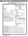
EU-Konformitätserklärung/EU-Declaration of conformity/
Déclaration UE de conformité

Pulscon LTC50, LTC51
SI01135O-D
DOCT-3767 2015-04 272459
4

Pulscon LTC50, LTC51
SI01135O-D
DOCT-3767 2015-04 272459
15
EN
Pulscon
LTC50, LTC51
2-wire, 4 mA ... 20 mA HART, 4 mA ... 20 mA
Table of Contents
Associated documentation. . . . . . . . . . . . . . . . . . . . . . . . . . . . . . . . . . . . . . . . . . . . . . . . . . . . . . 16
Supplementary documentation . . . . . . . . . . . . . . . . . . . . . . . . . . . . . . . . . . . . . . . . . . . . . . . . . . 16
General notes: Combined approval. . . . . . . . . . . . . . . . . . . . . . . . . . . . . . . . . . . . . . . . . . . . . . . 16
Manufacturer's certificates . . . . . . . . . . . . . . . . . . . . . . . . . . . . . . . . . . . . . . . . . . . . . . . . . . . . . . 16
Extended order code . . . . . . . . . . . . . . . . . . . . . . . . . . . . . . . . . . . . . . . . . . . . . . . . . . . . . . . . . . 17
Intrinsic safety Ex i (Part 1)
Safety instructions: General . . . . . . .. . . . . . . . . . . . . . . . . . . . . . . . . . . . . . . . . . . . . . . . . . . . . . 18
Safety instructions: Special conditions . . . . . . . . . . . . . . . . . . . . . . . . . . . . . . . . . . . . . . . . . . . .18
Safety instructions: Installation . . . . . .. . . . . . . . . . . . . . . . . . . . . . . . . . . . . . . . . . . . . . . . . . . . . 18
Safety instructions: Zone 0. . . . . . . . . . . . . . . . . . . . . . . . . . . . . . . . . . . . . . . . . . . . . . . . . . . . . . 19
Temperature tables. . . . . . . . . . . . . . . . . . . . . . . . . . . . . . . . . . . . . . . . . . . . . . . . . . . . . . . . . . . . 19
Connection data . . . . . . . . . . . . . . . . . . . . . . . . . . . . . . . . . . . . . . . . . . . . . . . . . . . . . . . . . . . . . . 20
Flameproof enclosure Ex d (Part 2)
Safety instructions: General . . . . . . .. . . . . . . . . . . . . . . . . . . . . . . . . . . . . . . . . . . . . . . . . . . . . . 20
Safety instructions: Special conditions . . . . . . . . . . . . . . . . . . . . . . . . . . . . . . . . . . . . . . . . . . . .20
Safety instructions: Installation . . . . . .. . . . . . . . . . . . . . . . . . . . . . . . . . . . . . . . . . . . . . . . . . . . . 21
Safety instructions: Zone 0. . . . . . . . . . . . . . . . . . . . . . . . . . . . . . . . . . . . . . . . . . . . . . . . . . . . . . 21
Temperature tables. . . . . . . . . . . . . . . . . . . . . . . . . . . . . . . . . . . . . . . . . . . . . . . . . . . . . . . . . . . . 22
Connection data . . . . . . . . . . . . . . . . . . . . . . . . . . . . . . . . . . . . . . . . . . . . . . . . . . . . . . . . . . . . . . 22

Pulscon LTC50, LTC51
SI01135O-D
DOCT-3767 2015-04 272459
16
EN
Associated
documentation
This document is an integral part of the following Operating Instructions:
BA01000O, BA01001O
The Operating Instructions pertaining to the device apply.
Supplementary
documentation
Explosion-protection manual
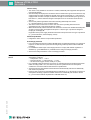
General notes:
Combined approval
The device is suitable for installation with explosion protection "intrinsic safety Ex i" or "flameproof
enclosure Ex d".
• Before initial commissioning, specify the type of protection.
• It is not permitted to change the type of protection after initial commissioning as this can
jeopardize the explosion protection.
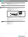
For aluminum housings:
Void out the explosion protection that is not used on the nameplate.
Figure 1
For stainless steel housings:
Using a striking tool, mark the explosion protection used, or void out the explosion protection that is
not used.
Caution!
Depending on the type of protection used, observe the following safety instructions for installation
with explosion protection "intrinsic safety" (Part 1) or "flameproof enclosure" (Part 2).
Manufacturer's
certificates
EU-Declaration of conformity
seepage3
EC type-examination certificate
Certificate number:
DEKRA 14 ATEX 0117X
Dat.:Dat.:
KEMA XX ATEX XXXX
Ex ia
Avoid electrostatic discharge!Avoid electrostatic discharge!
Mat.:Mat.:Mat.:Mat.:
IP6XIP6XIP6XIP6X
Ex d
Do not open, w
atmosphere is
Do not open, w
atmosphere is
cable ecable e
Ex d
Do not op

Pulscon LTC50, LTC51
SI01135O-D
DOCT-3767 2015-04 272459
17
EN
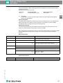
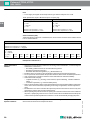
Extended order code The extended order code is indicated on the nameplate, which is affixed to the device in such a way
that it is clearly visible. Additional information about the nameplate is provided in the associated
Operating Instructions.
Structure of the extended order code:
Basic specifications
The features that are absolutely essential for the device (mandatory features) are specified in the
basic specifications. The number of positions depends on the number of features available.
The selected option of a feature can consist of several positions.
Optional specifications
The optional specifications describe additional features for the device (optional features). The
number of positions depends on the number of features available.
More detailed information about the device is provided in the following tables. These tables describe
the individual positions and IDs in the extended order code which are relevant to hazardous
locations.
Basic specifications
Optional specifications
Device type Basic specifications Optional specifications
LTC5X – X-XXXXX-XXXXX-XX XXXXX + XXXXXXXXXX
X = Placeholder
At this position, an option (number or letter) selected from the specification is displayed
instead of the placeholders.
Selected Option Position Description
Approval LTC5X-X-XXXXX-XXXXX-
XX
XXXXX EW ATEX II 1/2G Ex ia IIC T6-T1 Ga/Gb
ATEX II 1/2G Ex d [ia] IIC T6-T1 Ga/Gb
Electrical output LTC5X-X-XXXXX-XX
XX
X-XX XXXXX IE 2-wire, 4 mA ... 20 mA HART, 4 mA ... 20 mA
Display, operation LTC5X-X-XXXXX-XXXX
X
-XX XXXXX B
D
E
without display, via communication
SD02, 4-line, push-buttons and data backup function
SD03, 4-line, illuminated, touch control and data backup function
Housing LTC5X-X-XXXXX-
XX
XXX-XX XXXXX A2 GT20 dual compartment, alu coated
LTC51-X-XXXXX-
XX
XXX-XX XXXXX A3 GT18 dual compartment, 316L
Seal LTC50-X-XXXX
X
-XXXXX-XX XXXXX 2 Viton, -20 °C ... 80 °C
LTC51-X-XXXX
X
-XXXXX-XX XXXXX 3
4
5
EPDM, -40 °C ... 120 °C
Kalrez, -20 °C ... 200 °C
Viton, -30 °C ... 150 °C
Selected Option Position Description
Probe design XXXXXX
X
XXX B Sensor remote, 3 m cable, detachable, with mounting bracket

Pulscon LTC50, LTC51
SI01135O-D
DOCT-3767 2015-04 272459
18
EN
Intrinsic safety Ex i
Safety instructions:
General
• Staff must meet the following conditions for mounting, electrical installation, commissioning and
maintenance of the device:
– Be suitably qualified for their role and the tasks they perform
– Be trained in explosion protection
– Be familiar with national regulations (e. g. IEC/EN 60079-14)
• Install the device according to the manufacturer's instructions and national regulations.
• Do not operate the device outside the specified electrical, thermal and mechanical parameters.
• Only use the device in media to which the wetted materials have sufficient durability.
• Avoid electrostatic charging:
– Of plastic surfaces (e. g. housing, sensor element, special varnishing , attached additional
plates, ...)
– Of isolated capacities (e. g. isolated metallic plates)
• Refer to the temperature tables for the relationship between the permitted ambient temperature
for the sensor and/or transmitter, depending on the range of application, and the temperature
class.
• Modifications to the device can affect the explosion protection and must be carried out by staff
authorized to perform such work by Pepperl+Fuchs.
• When replacing the probe electronics or opening the connection between the remote cable and
the probe, a jumper plug must be used or a short-circuit must be established between the probe
contact and the potential equalization conductor to avoid electrostatically charging the probe.
Safety instructions:
Special conditions
Permitted ambient temperature range at the electronics housing: 40 °C T
amb
+80 °C.
Observe the information in the temperature tables.
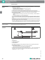
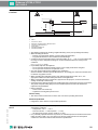
Safety instructions:
Installation
Figure 2
AZone 1
1 Tank; Zone 0, Zone 1
2 Electronic insert
3 Certified associated apparatus
4 Potential equalization line
5 Potential equalization
• After aligning (rotating) the housing, retighten the fixing screw (see Operating Instructions).
• When mounting the device:
– Exclude any mechanical damage or friction during the application.
– Pay particular attention to flow conditions and tank fittings.
• Continuous service temperature of the connecting cable: -40 °C ... +85 °C; in accordance with
the range of service temperature taking into account additional influences of the process
conditions (T
amb,min
), (T
amb, max
+ 20 K).
A
–
+
1
2
4
4
5
3

Pulscon LTC50, LTC51
SI01135O-D
DOCT-3767 2015-04 272459
19
EN
Intrinsic safety
• The device is only suitable for connection to certified, intrinsically safe equipment with explosion
protection Ex ia/Ex ib.
• The intrinsically safe input power circuit of the device is isolated from ground. If the device is only
equipped with one input, the dielectric strength of the input is at least 500 V
rms
. If the device is
equipped with more than one input, the dielectric strength of each individual input to ground is at
least 500 V
rms
, and the dielectric strength of the inputs vis-à-vis one another is also at least
500 V
rms
.
• Observe the pertinent guidelines when interconnecting intrinsically safe circuits
(e. g. IEC/EN 60079-14, Proof of Intrinsic Safety).
• The device can be connected to a service tool: refer to the Operating Instructions and
specifications in the "Overvoltage protection" chapter.
• When the intrinsically safe Ex ia circuits of the device are connected to certified intrinsically safe
circuits of Category Ex ib for Equipment Groups IIC or IIB, the type of protection changes to
Ex ib[ia] IIC or Ex ib[ia] IIB.
Regardless of the power supply, all the internal circuits correspond to Ex ia IIC type of protection
(e. g. service interface, external display, sensor).
Potential equalization
• Integrate the device into the local potential equalization.
Overvoltage protection
• If an overvoltage protection according to IEC/EN 60079-14 against atmospheric over voltages is
required: no other circuits may leave the housing during normal operation without additional
measures.
• For installations which require overvoltage protection to comply with national regulations or
standards (e. g. IEC/EN 60079-14), install the device using overvoltage protection.
• Observe the safety instructions of the overvoltage protection.
Safety instructions:
Zone 0
• In the event of potentially explosive vapor/air mixtures, only operate the device under
atmospheric conditions.
– Temperature: -20 °C ... +60 °C
– Pressure: 80 kPa ... 110 kPa (0,8 bar ... 1,1 bar)
– Air with normal oxygen content, usually 21 % (V/V)
• If no potentially explosive mixtures are present, or if additional protective measures have been
taken according to EN 1127-1, the device may also be operated under non-atmospheric
conditions in accordance with the manufacturer's specifications.
• Associated devices with galvanic isolation between the intrinsically safe and non-intrinsically
safe circuits are preferred.
• If there is a risk of dangerous potential differences within Zone 0 (e. g. through the occurrence of
atmospheric electricity), implement suitable measures for intrinsically safe circuits in Zone 0
(e. g. in accordance with the requirements of IEC/EN 60079-14).
Temperature tables seepage35

Pulscon LTC50, LTC51
SI01135O-D
DOCT-3767 2015-04 272459
20
EN
Connection data Basic specification, option "Approval" = EW
Ex ia
• Power supply and signal circuit with protection type: intrinsic safety Ex ia IIC or IIB.
Service interface (CDI)
Taking the following values into consideration, the device can be connected to the certified service
tool or a similar interface:
Flameproof enclosure Ex d
Safety instructions:
General
• Staff must meet the following conditions for mounting, electrical installation, commissioning and
maintenance of the device:
– Be suitably qualified for their role and the tasks they perform
– Be trained in explosion protection
– Be familiar with national regulations (e. g. IEC/EN 60079-14)
• Install the device according to the manufacturer's instructions and national regulations.
• Do not operate the device outside the specified electrical, thermal and mechanical parameters.
• Only use the device in media to which the wetted materials have sufficient durability.
• Avoid electrostatic charging:
– Of plastic surfaces (e. g. housing, sensor element, special varnishing , attached additional
plates, ...)
– Of isolated capacities (e. g. isolated metallic plates)
• Refer to the temperature tables for the relationship between the permitted ambient temperature
for the sensor and/or transmitter, depending on the range of application, and the temperature
class.
• Modifications to the device can affect the explosion protection and must be carried out by staff
authorized to perform such work by Pepperl+Fuchs.
• When replacing the probe electronics or opening the connection between the remote cable and
the probe, a jumper plug must be used or a short-circuit must be established between the probe
contact and the potential equalization conductor to avoid electrostatically charging the probe.
Safety instructions:
Special conditions
Permitted ambient temperature range at the electronics housing: -40 °C T
amb
+80 °C.
Observe the information in the temperature tables.
Basic specification, Option "Electrical output" = IE (TRC [04])
Terminal 1 (+), 2 (–) Terminal 3 (+), 4 (–)
Power supply: Output 4 mA ... 20 mA:
U
i
= 30 V
I
i
= 300 mA
P
i
= 1 W
U
i
= 30 V
I
i
= 300 mA
P
i
= 1 W
effective inner inductance L
i
= 0 µH
effective inner capacitance C
i
= 30 nF
effective inner inductance L
i
= 0 µH
effective inner capacitance C
i
= 30 nF
Service interface
U
i
= 7.3 V
effective inner inductance L
i
= negligible
effective inner capacitance C
i
= negligible
U
o
= 7.3 V
I
o
= 100 mA
P
o
= 160 mW
L
o
(mH) =
C
o
(µF) =
5.00
0.73
2.00
1.20
1.00
1.60
0.50
2.00
0.20
2.60
0.10
3.20
0.05
4.00
0.02
5.50
0.01
7.30
0.005
10.00
0.002
12.70
0.001
12.70

Pulscon LTC50, LTC51
SI01135O-D
DOCT-3767 2015-04 272459
21
EN
Safety instructions:
Installation
Figure 3
AZone 1
1 Tank; Zone 0, Zone 1
2 Electronics compartment Ex ia; Electronic insert
3 Connection compartment Ex d
4 Power supply
5 Potential equalization line
6 Potential equalization
• After aligning (rotating) the housing, retighten the fixing screw (see Operating Instructions).
• When mounting the device:
– Exclude any mechanical damage or friction during the application.
– Pay particular attention to flow conditions and tank fittings.
• Continuous service temperature of the connecting cable: -40 °C ... +85 °C; in accordance with
the range of service temperature taking into account additional influences of the process
conditions
(T
amb,min
), (T
amb,max
+20 K).
• In potentially explosive atmospheres:
– Do not open the electrical connection of the power supply circuit when energized.
– Do not open the connection compartment cover.
• Only use certified cable entries suitable for the application.
Observe selection criteria as per IEC/EN 60079-14. Accordingly, the connection terminal does
not include any ignition sources.
• When operating the transmitter housing at an ambient temperature under -20 °C, use
appropriate cables and cable entries permitted for this application.
• When connecting through a conduit entry approved for this purpose, mount the associated
sealing unit directly at the housing.
• Seal unused entry glands with approved sealing plugs that correspond to the type of protection.
The plastic transport sealing plug does not meet this requirement and must therefore be
replaced during installation.
• Before operation:
– Screw in the cover all the way.
– Tighten the securing clamp on the cover.
Intrinsic safety
• The device can be connected to a service tool: refer to the Operating Instructions.
Potential equalization
• Integrate the device into the local potential equalization.
Safety instructions:
Zone 0
• In the event of potentially explosive vapor/air mixtures, only operate the device under
atmospheric conditions.
– Temperature: -20 °C ... +60 °C
– Pressure: 80 kPa ... 110 kPA (0.8 bar ... 1.1 bar)
– Air with normal oxygen content, usually 21 % (V/V)
• If no potentially explosive mixtures are present, or if additional protective measures have been
taken according to EN 1127-1, the device may also be operated under non-atmospheric
conditions in accordance with the manufacturer's specifications.
A
–
+
1
2
3
5
5
6
4

Pulscon LTC50, LTC51
SI01135O-D
DOCT-3767 2015-04 272459
22
EN
Temperature tables seepage35
Connection data Basic specification, option "Approval" = EW
Connection compartment Ex d
Electronics compartment Ex ia
Service interface (CDI)
Taking the following values into consideration, the device can be connected to the certified service
tool or a similar interface:
Basic specification, Option "Electrical output" = IE (TRC [05])
Terminal 1 (+), 2 (–) Terminal 3 (+), 4 (–)
Power supply: Output 4 mA ... 20 mA:
U
N
= 30 V DC
U
m
= 250 V AC
I
max
= 22 mA
U
N
= 30 V DC
U
m
= 250 V AC
I
max
= 22 mA
Service interface
U
i
= 7.3 V
effective inner inductance L
i
= negligible
effective inner capacitance C
i
= negligible
U
o
= 7.3 V
I
o
= 100 mA
P
o
= 160 mW
L
o
(mH) =
C
o
(µF) =
5.00
0.73
2.00
1.20
1.00
1.60
0.50
2.00
0.20
2.60
0.10
3.20
0.05
4.00
0.02
5.50
0.01
7.30
0.005
10.00
0.002
12.70
0.001
12.70

Pulscon LTC50, LTC51
SI01135O-D
DOCT-3767 2015-04 272459
35
Temperaturtabellen/Temperature tables/
Tableaux des températures
Inhaltsverzeichnis/Table of Contents/Sommaire
Allgemeine Hinweise/General notes/Généralités 36
Diagramm/Diagram/Diagramme 38
Sonden-Design: kompakt/Probe design: compact/Construction de sonde :
compacte
Ex i Ex d
Sonde und Elektronikgehäuse/Probe and electronics housing/Sonde et boîtier de
l'électronique : Zone 1
LTC50 . . . . . . . . . . . . . . . . . . . . . . . . . . . . . . . . . . . . . . . . . . . . . . . . . . . . . . . . . . . . . . . . 39 42
LTC51 . . . . . . . . . . . . . . . . . . . . . . . . . . . . . . . . . . . . . . . . . . . . . . . . . . . . . . . . . . . . . . . . 40 43
Sonde/Probe/Sonde : Zone 0
Elektronikgehäuse/Electronics housing/Boîtier de l'électronique : Zone 1
LTC5X . . . . . . . . . . . . . . . . . . . . . . . . . . . . . . . . . . . . . . . . . . . . . . . . . . . . . . . . . . . . . . . . 41 44
Sonden-Design: abgesetzt/Probe design: remote/Construction de sonde : séparée Ex i Ex d
Sonde/Probe/Sonde : Zone 0, Zone 1
Elektronikgehäuse/Electronics housing/Boîtier de l'électronique : Zone 1
LTC5X . . . . . . . . . . . . . . . . . . . . . . . . . . . . . . . . . . . . . . . . . . . . . . . . . . . . . . . . . . . . . . . . 41 44

Pulscon LTC50, LTC51
SI01135O-D
DOCT-3767 2015-04 272459
36
Allgemeine Hinweise Wenn nicht anders angegeben, beziehen sich die Positionen immer auf die Grundspezifikation.
Hinweis!
Zulässigen Temperaturbereich an der Sonde beachten.
Auswahltabelle
General notes Unless otherwise indicated, the positions always refer to the basic specification.
Note!
Observe the permitted temperature range at the probe.
Selection table
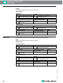
Betriebsart: Ex i
Zulassung Gehäuse
EW ATEX II 1/2G Ex ia IIC T6-T1 Ga/Gb
ATEX II 1/2G Ex d [ia] IIC T6-T1 Ga/Gb
A2
A3
GT20 Zweikammer, Alu beschichtet
GT18 Zweikammer, 316L
Elektrischer Ausgang Transmission code des
Anschlussklemmenmoduls
Kanäle
IE 2-Draht, 4 mA ... 20 mA HART,
4mA...20mA
TRC [04] 1 oder 2 Kanäle benutzt
Betriebsart: Ex d
Zulassung Gehäuse
EW ATEX II 1/2G Ex ia IIC T6-T1 Ga/Gb
ATEX II 1/2G Ex d [ia] IIC T6-T1 Ga/Gb
A2
A3
GT20 Zweikammer, Alu beschichtet
GT18 Zweikammer, 316L
Elektrischer Ausgang Transmission code des
Anschlussklemmenmoduls
Kanäle
IE 2-Draht, 4 mA ... 20 mA HART,
4mA...20mA
TRC [05] 1 oder 2 Kanäle benutzt
Operation mode: Ex i
Approval Housing
EW ATEX II 1/2G Ex ia IIC T6-T1 Ga/Gb
ATEX II 1/2G Ex d [ia] IIC T6-T1 Ga/Gb
A2
A3
GT20 dual compartment, Alu coated
GT18 dual compartiment, 316L
Elektrical output Transmission code of the
terminal module
Channels
IE 2-wire, 4 mA ... 20 mA HART,
4mA...20mA
TRC [04] 1 or 2 channels used
Operation mode: Ex d
Approval Housing
EW ATEX II 1/2G Ex ia IIC T6-T1 Ga/Gb
ATEX II 1/2G Ex d [ia] IIC T6-T1 Ga/Gb
A2
A3
GT20 dual compartment, Alu coated
GT18 dual compartiment, 316L
Elektrical output Transmission code of the
terminal module
Channels
IE 2-wire, 4 mA ... 20 mA HART,
4mA...20mA
TRC [05] 1 or 2 channels used

Pulscon LTC50, LTC51
SI01135O-D
DOCT-3767 2015-04 272459
37
Généralités Sauf indication contraire, les positions se réfèrent toujours aux spécifications de base.
Remarque !
Tenir compte de la gamme de température admissible à la sonde.
Tableau de sélection
Mode d’opération : Ex i
Agrément Boîtier
EW ATEX II 1/2G Ex ia IIC T6-T1 Ga/Gb
ATEX II 1/2G Ex d [ia] IIC T6-T1 Ga/Gb
A2
A3
GT20 double compartiment, alu revêtu
GT18 double compartiment, 316L
Sortie électrique Code de transmission du
module de raccordement
Voies
IE 2-fils, 4 mA ... 20 mA HART,
4mA...20mA
TRC [04] 1 ou 2 voies utilisées
Mode d’opération : Ex d
Agrément Boîtier
EW ATEX II 1/2G Ex ia IIC T6-T1 Ga/Gb
ATEX II 1/2G Ex d [ia] IIC T6-T1 Ga/Gb
A2
A3
GT20 double compartiment, alu revêtu
GT18 double compartiment, 316L
Sortie électrique Code de transmission du
module de raccordement
Voies
IE 2-fils, 4 mA ... 20 mA HART,
4mA...20mA
TRC [05] 1 ou 2 voies utilisées

Pulscon LTC50, LTC51
SI01135O-D
DOCT-3767 2015-04 272459
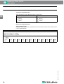
38
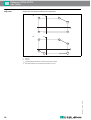
Diagramm/Diagram/
Diagramme
Beispieldiagramme zu den Temperaturtabellen/Example diagrames to the temperature tables/
Diagrammes d'exemple aux tableaux des températures
Abbildung/Figure/Figure 1
AVersion 1
BVersion 2
T
amb
Umgebungstemperatur/Ambient temperature/Température ambiante
T
p
Prozesstemperatur/Process temperature/Température de process
Tamb
A
Tamb
B
Tp
Tp
P 1
P 1
P 2
P 2
P 5
P 5
P 6
P 3
P 3
P 4
P 4

Pulscon LTC50, LTC51
SI01135O-D
DOCT-3767 2015-04 272459
39
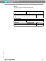
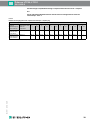
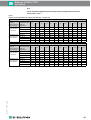
Sonden-Design: kompakt/Probe design: compact/Construction de sonde : compacte
Ex i
Sonde und Elektronikgehäuse/Probe and electronics housing/Sonde et boîtier de
l'électronique : Zone 1
LTC50
Elektrischer Ausgang/Electrical output/Sortie électrique = IE (TRC [04])
Gehäuse/Housing/Boîtier = A2
Elektrischer
Ausgang/
Electrical output/
Sortie électrique
Temperaturklasse/
Temperature class/
Classe de
température
P 1 P 2 P 3 P 4 P 5 P 6
T
p
T
amb
T
p
T
amb
T
p
T
amb
T
p
T
amb
T
p
T
amb
T
p
T
amb
1 Kanal benutzt/
1 channel used/
1 voie utilisée
T6 (85 °C) -20 °C 60 °C 60 °C 60 °C 80 °C 56 °C 80 °C -20 °C -20 °C -20 °C – –
2 Kanäle benutzt/
2 channels used/
2 voies utilisées
T6 (85 °C) -20 °C 54 °C 54 °C 54 °C 80 °C 52 °C 80 °C -20 °C -20 °C -20 °C – –

Pulscon LTC50, LTC51
SI01135O-D
DOCT-3767 2015-04 272459
40
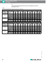
Ex i
Sonde und Elektronikgehäuse/Probe and electronics housing/Sonde et boîtier de
l'électronique : Zone 1
LTC51
Elektrischer Ausgang/Electrical output/Sortie électrique = IE (TRC [04])
Gehäuse/Housing/Boîtier = A2
Elektrischer
Ausgang/
Electrical output/
Sortie électrique
Temperaturklasse/
Temperature class/
Classe de
température
P 1 P 2 P 3 P 4 P 5 P 6
T
p
T
amb
T
p
T
amb
T
p
T
amb
T
p
T
amb
T
p
T
amb
T
p
T
amb
1 Kanal benutzt/
1 channel used/
1 voie utilisée
T6 (85 °C) -40 °C 60 °C 60 °C 60 °C 85 °C 53 °C 85 °C -40 °C -40 °C -40 °C – –
T5 (100 °C) -40 °C 75 °C 75 °C 75 °C 100 °C 68 °C 100 °C -40 °C -40 °C -40 °C – –
T4 (135 °C) -40 °C 80 °C 80 °C 80 °C 135 °C 70 °C 135 °C -40 °C -40 °C -40 °C – –
T3 (200 °C) -40 °C 80 °C 80 °C 80 °C 200 °C 56 °C 200 °C -40 °C -40 °C -40 °C – –
2 Kanäle benutzt/
2 channels used/
2 voies utilisées
T6 (85 °C) -40 °C 54 °C 54 °C 54 °C 85 °C 48 °C 85 °C -40 °C -40 °C -40 °C – –
T5 (100 °C) -40 °C 69 °C 69 °C 69 °C 100 °C 63 °C 100 °C -40 °C -40 °C -40 °C – –
T4 (135 °C) -40 °C 78 °C 78 °C 78 °C 135 °C 66 °C 135 °C -40 °C -40 °C -40 °C – –
T3 (200 °C) -40 °C 78 °C 78 °C 78 °C 200 °C 53 °C 200 °C -40 °C -40 °C -40 °C – –
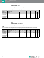
Gehäuse/Housing/Boîtier = A3
Elektrischer
Ausgang/
Electrical output/
Sortie électrique
Temperaturklasse/
Temperature class/
Classe de
température
P 1 P 2 P 3 P 4 P 5 P 6
T
p
T
amb
T
p
T
amb
T
p
T
amb
T
p
T
amb
T
p
T
amb
T
p
T
amb
1 Kanal benutzt/
1 channel used/
1 voie utilisée
T6 (85 °C) -40 °C 60 °C 60 °C 60 °C 85 °C 51 °C 85 °C -40 °C -40 °C -40 °C – –
T5 (100 °C) -40 °C 75 °C 75 °C 75 °C 100 °C 66 °C 100 °C -40 °C -40 °C -40 °C – –
T4 (135 °C) -40 °C 80 °C 80 °C 80 °C 135 °C 68 °C 135 °C -40 °C -40 °C -40 °C – –
T3 (200 °C) -40 °C 80 °C 80 °C 80 °C 200 °C 48 °C 200 °C -40 °C -40 °C -40 °C – –
2 Kanäle benutzt/
2 channels used/
2 voies utilisées
T6 (85 °C) -40 °C 54 °C 54 °C 54 °C 85 °C 46 °C 85 °C -40 °C -40 °C -40 °C – –
T5 (100 °C) -40 °C 69 °C 69 °C 69 °C 100 °C 61 °C 100 °C -40 °C -40 °C -40 °C – –
T4 (135 °C) -40 °C 78 °C 78 °C 78 °C 135 °C 64 °C 135 °C -40 °C -40 °C -40 °C – –
T3 (200 °C) -40 °C 78 °C 78 °C 78 °C 200 °C 48 °C 200 °C -40 °C -40 °C -40 °C – –

Pulscon LTC50, LTC51
SI01135O-D
DOCT-3767 2015-04 272459
41
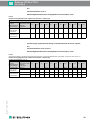
Ex i
Sonde/Probe/Sonde : Zone 0
Elektronikgehäuse/Electronics housing/Boîtier de l'électronique : Zone 1
1
LTC50, ohne abgesetzten Sensor/without remote sensor/sanssonde séparée = -20 °C
Sonden-Design: abgesetzt/Probe design: remote/Construction du sonde : séparée
Ex i
Sonde/Probe/Sonde : Zone 0, Zone 1
Elektronikgehäuse/Electronics housing/Boîtier de l'électronique : Zone 1
T
p
= abhängig vom Sensor/dependent on the sensor/dépend du capteur
LTC5X
Elektrischer Ausgang/Electrical output/Sortie électrique = IE (TRC [04])
Gehäuse/Housing/Boîtier = A2, A3
Elektrischer
Ausgang/
Electrical output/
Sortie électrique
Temperaturklasse/
Temperature class/
Classe de
température
P 1 P 2 P 3 P 4 P 5 P 6
T
p
T
amb
T
p
T
amb
T
p
T
amb
T
p
T
amb1
T
p
T
amb1
T
p
T
amb
1 Kanal benutzt/
1 channel used/
1 voie utilisée
T6 (85 °C) -20 °C 60 °C 60 °C 60 °C 60 °C 60 °C 60 °C -40 °C -20 °C -40 °C – –
2 Kanäle benutzt/
2 channels used/
2 voies utilisées
T6 (85 °C) -20 °C 53 °C 53 °C 53 °C 60 °C 53 °C 60 °C -40 °C -20 °C -40 °C – –
LTC5X
Optionale Spezifikation, Sonden-Design/Optional specification, Probe design/Spécifications optionnelles, Construction de la sonde = B
Elektrischer Ausgang/Electrical output/Sortie électrique = IE (TRC [04])
Gehäuse/Housing/Boîtier = A2, A3
Elektrischer
Ausgang/
Electrical output/
Sortie électrique
Temperaturklasse/
Temperature class/
Classe de
température
P 1 P 2 P 3 P 4 P 5 P 6
T
p
T
amb
T
p
T
amb
T
p
T
amb
T
p
T
amb
T
p
T
amb
T
p
T
amb
1 Kanal benutzt/
1 channel used/
1 voie utilisée
T6 (85 °C) – 60 °C – 60 °C – 60 °C – -40 °C – -40 °C – –
T5 (100 °C) – 80 °C – 80 °C – 80 °C – -40 °C – -40 °C – –
2 Kanäle benutzt/
2 channels used/
2 voies utilisées
T6 (85 °C) – 54 °C – 54 °C – 54 °C – -40 °C – -40 °C – –
T5 (100 °C) – 78 °C – 78 °C – 78 °C – -40 °C – -40 °C – –

Pulscon LTC50, LTC51
SI01135O-D
DOCT-3767 2015-04 272459
42
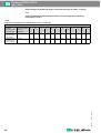
Sonden-Design: kompakt/Probe design: compact/Construction de sonde : compacte
Ex d
Sonde und Elektronikgehäuse/Probe and electronics housing/Sonde et boîtier de
l'électronique : Zone 1
LTC50
Elektrischer Ausgang/Electrical output/Sortie électrique = IE (TRC [05])
Gehäuse/Housing/Boîtier = A2
Elektrischer
Ausgang/
Electrical output/
Sortie électrique
Temperaturklasse/
Temperature class/
Classe de
température
P 1 P 2 P 3 P 4 P 5 P 6
T
p
T
amb
T
p
T
amb
T
p
T
amb
T
p
T
amb
T
p
T
amb
T
p
T
amb
1 Kanal benutzt/
1 channel used/
1 voie utilisée
T6 (85 °C) -20 °C 60 °C 60 °C 60 °C 80 °C 56 °C 80 °C -20 °C -20 °C -20 °C – –
2 Kanäle benutzt/
2 channels used/
2 voies utilisées
T6 (85 °C) -20 °C 60 °C 60 °C 60 °C 80 °C 56 °C 80 °C -20 °C -20 °C -20 °C – –
Pagina se încarcă...
Pagina se încarcă...
Pagina se încarcă...
Pagina se încarcă...
-
 1
1
-
 2
2
-
 3
3
-
 4
4
-
 5
5
-
 6
6
-
 7
7
-
 8
8
-
 9
9
-
 10
10
-
 11
11
-
 12
12
-
 13
13
-
 14
14
-
 15
15
-
 16
16
-
 17
17
-
 18
18
-
 19
19
-
 20
20
-
 21
21
-
 22
22
-
 23
23
-
 24
24


Pepperl+Fuchs LTC51 Manual de utilizare
- Tip
- Manual de utilizare
- Acest manual este potrivit și pentru
în alte limbi
- English: Pepperl+Fuchs LTC51 User manual
Lucrări înrudite
-
Pepperl+Fuchs LTC51 Manual de utilizare
-
-
-
-
-
-
-
-
-