
English
for Europe, Asia, Africa, Oceania,
and Latin America
Owner’s Manual
Digital Sound Projector
TM

2 En
The “ ” logo and “IntelliBeam” are trademarks of Yamaha
Corporation.
The “ ” logo and “Cinema DSP” are registered trademarks of
Yamaha Corporation.
The “ ” and “UniVolume” are trademarks of Yamaha Corporation.
The “ ” and “AirWired” are trademarks of Yamaha Corporation.
Manufactured under license from Dolby Laboratories.
Dolby, Pro Logic and the double-D symbol are trademarks of Dolby
Laboratories
Manufactured under license under U.S. Patent No’s:
5,451,942;5,956,674;5,974,380;5,978,762;6,226,616;6,487,535 & other U.S. and
worldwide patents issued & pending. DTS is a registered trademark and the DTS
logos, Symbol, DTS-HD and DTS-HD Master Audio are trademark of DTS, Inc. ©
1996-2007 DTS, Inc. All Rights Reserved.
Manufactured under license from Cambridge Mechatronics Ltd. Worldwide
patents applied for.
The “ ” logo and “Digital Sound Projector
™
” are trademarks of
Cambridge Mechatronics Ltd.
“HDMI”, the “HDMI” logo and “High-Definition Multimedia Interface” are
trademarks or registered trademarks of HDMI Licensing LLC.
x.v.Color
“x.v.Color” is a trademark.
iPod™, iPhone™
iPod is a trademark of Apple Inc., registered in the U.S. and other countries.
iPhone is a trademark of Apple Inc.
“Made for iPod” means that an electronic accessory has been designed to
connect specifically to iPod and has been certified by the developer to meet
Apple performance standards.
“Works with iPhone” means that an electronic accessory has been designed to
connect specifically to iPhone and has been certified by the developer to meet
Apple performance standards.
Apple is not responsible for the operation of this device or its compliance with
safety and regulatory standards.
About this manual
• Make sure you read precautions in “Safety and Accessory Information” (separate booklet) carefully before using this unit.
• This manual describes how to connect and operate this unit. For details regarding the operation of external components, refer to the
supplied owner’s manual for each component.
• Operations in this manual use keys on the supplied remote control of this unit unless otherwise specified.
• y indicates a tip for your operation.
• An illustration of the remote control in the left pages of this manual indicates the keys to be used in two facing (left and right) pages.
• This manual is produced prior to production. Designs and specifications are subject to change in part as a result of improvements,
etc. In case of differences between the manual and the product, the product has priority.

3 En
PREPARATIONINTRODUCTION APPENDIXPLAYBACK FEATURES SETTINGS
Features........................................................................... 4
General operation flow .................................................. 5
Controls and functions................................................... 6
Front panel .........................................................................6
Front panel display.............................................................7
Rear panel...........................................................................8
Remote control ...................................................................9
Installation .................................................................... 10
Connections................................................................... 12
Before connecting components........................................12
Connecting external components .....................................12
Connecting a subwoofer...................................................13
Connecting the FM antenna .............................................14
Preparing the remote control...................................... 14
Installing batteries in the remote control..........................14
Operation range of the remote control .............................14
Changing OSD language.............................................. 15
AUTO SETUP (IntelliBeam)....................................... 15
Installing the IntelliBeam microphone.............................15
Using AUTO SETUP (IntelliBeam) ................................16
Using the system memory............................................ 19
Saving settings .................................................................19
Loading settings ...............................................................19
Playback ........................................................................ 21
Playing back sources........................................................21
Playing back TV sounds...................................................21
Playing back a player .......................................................21
Muting audio output.........................................................21
Decoder and input channel indicators..............................21
Playback mode.............................................................. 22
Selecting surround or stereo playback .............................22
Enjoying CINEMA DSP programs..................................22
Changing the audio output method for surround
playback........................................................................23
Enjoying 2-channel sources in surround sound ...............24
Playing back 5.1-channel sources in
7.1-channel surround....................................................24
FM tuning ..................................................................... 25
Tuning into the desired FM station
(Frequency tuning) .......................................................25
Registering FM stations and tuning in (Preset tuning).....25
Displaying the Radio Data System information
(Europe model only).....................................................26
Playing back iPod™/iPhone™ .................................... 27
Useful features .............................................................. 28
Adjusting volume level automatically (UniVolume).......28
Using the HDMI™ control function ................................28
Using the sleep timer........................................................28
Configuring settings for each input source
(Option menu) ..............................................................28
Displaying the input signal information...........................29
Customizing this unit (SET MENU)........................... 30
SET MENU items............................................................ 30
Basic SET MENU operation............................................ 31
MANUAL SETUP........................................................... 31
SOUND SET MENU....................................................... 33
SOUND OUT MENU...................................................... 34
INPUT MENU................................................................. 35
DISPLAY MENU............................................................ 36
System configurations (ADVANCED SETUP) ......... 37
Using an external amplifier......................................... 38
Controlling external components ............................... 39
Troubleshooting ........................................................... 40
Glossary......................................................................... 43
Specifications ................................................................ 44
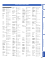
List of remote control codes ........................................ 45
Index.............................................................................. 52
CONTENTS
INTRODUCTION
PREPARATION
PLAYBACK FEATURES
SETTINGS
APPENDIX

4 En
INTRODUCTION
Digital Sound Projector
The Digital Sound Projector technology allows one slim unit to
control and steer multiple channels of sound to generate multi-
channel surround sound, thus eliminates the need for satellite
loudspeakers and cabling normally associated with conventional
surround sound systems. This unit also employs the beam modes that
let you enjoy the surround sound (5 Beam, Stereo+3 Beam, 3 Beam
for 5.1-channel audio, 5 Beam plus 2, Stereo + 3 Beam plus 2, 3
Beam for 7.1-channel audio) and 2-channel stereo playback.
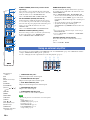
HDMI (High-Definition Multimedia Interface)
◆ HDMI input x 4, HDMI output x 1
◆ HDMI interface for standard, enhanced, or high-definition video
(including 1080p video signal transmission) as well as multi-channel
digital audio based on HDCP
– Automatic audio and video synchronization (lip sync) information
capability
– Deep Color video signal transmission capability
– “x.v.Color” video signal transmission capability
– High definition digital audio format signals capability
– Multi-channel Linear PCM signal capability
◆ Simple and easy connections with HDMI supported external components
◆ Functional link which enables the remote control of your TV to control
this unit (with an HDMI control-compatible TV)
– Power mode switch capability (on/standby)
– Volume adjustment capability
– TV sounds reproduce device selection capability (this unit/TV)
AUTO SETUP (IntelliBeam)
This unit employs the automatic sound beam and acoustic
optimization technology with the aid of the supplied IntelliBeam
microphone. You can avoid troublesome listening-based speaker
setup and achieve highly accurate sound beam adjustments that best
match your listening environment.
Cinema DSP
This unit employs the Cinema DSP technology developed by Yamaha
Electronics Corp. that lets you experience movies at home with all the
original dramatic sound impact.
UniVolume
This unit employs the automatic volume adjustment function. You
can limit the volume level of the TV so that it will not increase
suddenly when whenever the contents being broadcast change (due to
commercials, etc.).
Various digital audio decoders includes newly added HD
audio decoder, and sound technologies
◆ Dolby TrueHD, Dolby Digital Plus, Dolby digital Surround EX, Dolby
Digital, Dolby Pro Logic, Pro Logic II, Pro Logic IIx
◆ DTS-HD Master Audio, DTS-HD High Resolution Audio, DTS 96/24,
DTS-ES, DTS, DTS-ES (discrete and matrix), DTS Neo: 6
◆ Music Enhancer to improve the sound quality of compression artifacts
such as the MP3 format
◆ Bass Extension to produce powerful bass sounds
Sophisticated FM tuner
◆ 40-station random and direct preset tuning
◆ Automatic preset tuning
Radio Data System (Europe model only)
This unit employs the Radio Data System that is a data transmission
system used by FM stations.
Wireless connection (AirWired)
◆ Wireless connection with iPod/iPhone, using Yamaha wireless transmitter
for iPod (PDX-50TX/PDX-50BC)
◆ Wireless connection with subwoofer, using Yamaha wireless subwoofer
kit (SWK-W10) (not available in some countries)
◆ iPod/iPhone interlock feature to turn on/off this unit or switch the input
source in conjunction with iPod/iPhone operations
Versatile Remote Control
The supplied remote control comes with preset remote control codes
used to control external components connected to this unit.
Features

5 En
PREPARATIONINTRODUCTION APPENDIXPLAYBACK FEATURES SETTINGS
1 Install this unit and connect to other components.
“Installation” (page 10), “Connections” (page 12).
2 Run AUTO SETUP to optimize the beam and sound settings.
“AUTO SETUP (IntelliBeam)” (page 15).
3 Play back a source.
“Playback” (page 21).
4 Change the playback method (surround/stereo), CINEMA DSP and/or beam modes settings.
“Playback mode” (page 22).
5 Configure this unit’s settings and/or set remote control codes.
“Customizing this unit (SET MENU)” (page 30), “Controlling external components” (page 39).
General operation flow

6 En
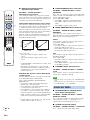
1 Remote control sensor
Receives infrared signals from the remote control (page 14).
2 Power LED
Lights up when the power is turned on (page 21).
3 Front panel display
Shows information about the operational status of this unit (page 7).
4 INPUT
Press repeatedly to switch between input sources.
5 VOLUME +/–
Controls the volume level of all audio channels.
Control range: MIN (minimum), 01 to 99, MAX (maximum)
6 Power (p) key
Turns on the power of this unit or sets it to the standby mode
(page 21).
Note
• In the standby mode, this unit consumes a small amount of power in order to
receive infrared signals from the remote control or to search for HDMI
signals.
7 INTELLIBEAM MIC jack
Connect the supplied IntelliBeam microphone for AUTO SETUP
(page 15).
Controls and functions
Front panel
INPUT VOLUME INTELLIBEAM MIC
64 7
321
5

7 En
PREPARATIONINTRODUCTION APPENDIXPLAYBACK FEATURES SETTINGS
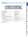
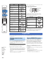
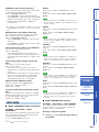
1 UNIVOLUME indicator
Lights up when the UniVolume function is turned on (page 28).
2 CINEMA DSP indicator
Lights up when a sound field program is selected (page 22).
3 HDMI indicator
Lights up when the signal of the selected input source is input from
the HDMI IN jack(s).
4 Tuner indicators
Light up when this unit is tuned into an FM station (page 25).
5 Radio Data System indicators (Europe model only)
Show the current Radio Data System status (page 26).
6 Wireless indicators
TRNS Lights up when a wireless connection is established
between the Yamaha wireless subwoofer kit (SWK-
W10) and this unit (page 13).
RECV Lights up when a wireless connection is established
between the Yamaha wireless transmitter for iPod (PDX-
50TX) and this unit (page 27).
7 Decoder indicators
Light up when the corresponding decoder operates
(page 21).
8 SLEEP indicator
Lights up when the sleep timer is set (page 28).
9 Volume level indicator
Displays the current volume level.
0 ENHANCER indicator
Lights up when the Music Enhancer is selected (page 34).
A BASS EXT indicator
Lights up when the bass extension mode is turned on (page 34).
B PCM indicator
Lights up when this unit is reproducing PCM (Pulse Code
Modulation) digital audio signals.
C Multi-information display
Shows information with alphanumeric characters when you adjust the
parameters of this unit. Current input source and audio output method
are displayed when this unit is turned on.
D Input channel indicators
The channel component of the current input signal is displayed
(page 21).
Front panel display
L C R
SL SB SR
EX1 LFE EX2
O
m
ft
dB
AUTO
UNIVOLUME
ENHANCER
BASS EXT
MEMORY
PS PTY RT CT
PCM
ES DSCRT MTRX
SLEEP
VOL
TUNED STEREO
RECVTRNS
HD MSTR HI
RES
Neo:6
96
24
q
DIGITAL PLUS
q
EX
q
TRUE HD
q
PL x
64 5 78921 3
D
CA0 B

8 En
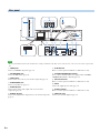
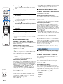
Note
• The rear panel illustration shows jacks and their names to help you find them easily. They are not exactly the same as the ones on the actual rear panel of this
unit.
1 HDMI jacks
Connect your HDMI components (page 12).
2 FM ANTENNA jack
Connect the FM antenna (page 14).
3 VIDEO jacks
Connect to the video jacks of your external components (page 12).
4 SUBWOOFER jack
Connect your subwoofer (page 13).
5 AUDIO IN jacks
Connect to the analog audio output jacks of your external
components (page 12).
6 DIGITAL IN jacks
Connect to the digital audio output jacks of your external components
(page 12).
7 IR IN terminal
This is a control expansion terminal for commercial use only.
8 SYSTEM CONNECTOR terminal
Use to connect a Yamaha subwoofer equipped with a SYSTEM
CONNECTOR terminal to this unit (page 13).
9 RS-232C terminal
This is a control expansion terminal for commercial use only.
0 AC IN
Connect the supplied power cable (page 12).
A IR-OUT terminal
This is a control expansion terminal for commercial use only.
B PRE OUT jacks
Connect your external amplifier (page 38).
Rear panel
AUX 1 TV
OUT
HDMI
AUX 2AUX 1 TVOUTIN
FRONT
PRE OUT
SURROUND SUR. BACK
CENTER
L
R
L
R
L
R
SUB
WOOFER
IR IN
SYSTEM
CONNECTOR
SUB
WOOFER
COMPONENT
DIGITAL INAUDIO INVIDEO
RS-232C
VIDEOVIDEO
Y
P
R PB
RR
LL
IN 1
IN 2
IN 3
IN 4
IR-OUT
AC IN
IR-OUT
OUT
HDMI
IN 1
IN 2
IN 3
IN 4
FM ANTENNA
FRONT
PRE OUT
SURROUND SUR. BACK
AUX 1 TVAUX 2AUX 1 TVOUTIN
IR IN
SYSTEM
CONNECTOR
SUB
WOOFER
COMPONENT
DIGITAL INAUDIO INVIDEO
RS-232C
1
0
7
A
2
93 5 6
B
4 8

9 En
PREPARATIONINTRODUCTION APPENDIXPLAYBACK FEATURES SETTINGS
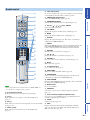
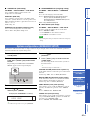
Note
• When operating the keys located on the slide cover (INFO, SLEEP, etc.),
close the slide cover completely before operation.
A Transmission indicator
Lights up when infrared control signals are being output.
B TV (p)
Turns on the power of your TV or set it to the standby mode
(page 39).
B AV (p)
Turns on the power of the selected component or set it to the standby
mode (page 39).
C Power (p) key
Turns on the power of this unit or set it to the standby mode
(page 21).
D Input selector keys
Use to select an input source (page 21). An input source key currently
selected lights up when the remote control is operated.
E CINEMA DSP program keys
Select the CINEMA DSP programs (page 22).
F SURROUND/STEREO
Switches between surround and stereo playback (page 22).
G Cursor ( / / / ) keys, ENTER
Select and adjust menu items.
H TOP MENU
Displays the top menu of a Blu-ray disc or DVD (page 39).
H MENU
Displays the menu of a Blu-ray disc or DVD (page 39).
I OPTION
Displays the option menu (page 28). The remote control turns to
setting mode (ISETUP lights up).
I SETUP
Displays the SETUP menu (page 30). Press and hold to directly enter
the LANGUAGE SETUP menu (page 15). Lights up when the
remote control is turned into the setting mode of the main unit.
I RETURN
Returns to the previous menu screen (page 31).
J CH /
Changes the channels of your TV/recorder (page 39).
K VOLUME +/–
Increases or decreases the volume level of this unit (page 21).
K MUTE
Mutes the sound. (page 21).
L TV operation keys
Use to control your TV (page 39).
M UNIVOLUME
Turns on or off the UniVolume function (page 28).
M SUR.DECODE
Selects a decoder for surround playback (page 24). The remote
control turns to setting mode (ISETUP lights up).
M INTELLIBEAM
Enters the AUTO SETUP menu (page 16). The remote control turns
to setting mode (ISETUP lights up).
N Numeric keys
Use to enter numbers.
O CODE SET
Sets remote control codes for external component operations
(page 39).
P Tuner / external component operation keys
Use to select or preset an FM station or control playback of your
external components (pages 25 and 39).
Q SLEEP
Sets the sleep timer (page 28).
R INFO
Displays information about signals currently input to this unit
(page 29). Select the desired Radio Data System display mode
(Europe model only) (page 26).
Remote control
0 +10
ENT
7 8 9
4 5 6
1 2 3
HDMI 4 iPod FM
ENTER
SURROUND STEREO
OFF
ENTER
TAINMENT
MUSIC
CINEMA DSP
MOVIE
HDMI 1 HDMI 2 HDMI 3
TV AUX 1 AUX 2
TV AV
MENUTOP MENU
OPTION
TV
MUTE
CODE SET
UNIVOLUME SUR. DECODE INTELLIBEAM
TV
INPUT MUTE
TV VOL CH VOLUME
SETUP RETURN
MEMORY
SLEEPINFO
TUNING PRESET
A
B
C
D
E
F
G
H
I
J
K
M
N
O
P
Q
R
L

10 En
PREPARATION
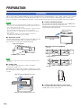
This section describes a suitable installation location to install this unit using a wall mount bracket, a rack, a table top stand or a floor stand. To
achieve desired surround sound effects, install this unit where there are no objects such as furniture obstructing the path of sound beams
(page 11). Depending on your installation environment, connections with external components (page 12) should be done before installation.
Notes
• Make sure you leave an adequate amount of ventilation space so that heat
can escape. We recommend installing this unit using a wall mount bracket, a
rack, a table top stand or a floor stand.
• Be sure to install this unit where it will not fall subject to vibrations, such as
from an earthquake, and where it is out of the reach of children.
• When using a cathode-ray tube (CRT) TV, do not install this unit directly
above your TV.
• If the picture on your TV screen becomes blurred or distorted, we
recommend moving this unit away from your TV.
■ Attach the stands
Attach the supplied stands to this unit as shown below. Make sure that
you attach the left and right stands correctly. These stands are
unnecessary if you use the optional wall mount bracket.
Note
• Depending on a rack, table top stand, or floor stand, the stands may not be
necessary.
■ Using a rack
You can install this unit either above or under your TV in a
commercially available rack.
It should be large enough to allow adequate ventilation space around
this unit and strong enough to support the weight of both this unit and
your TV.
■ Using a wall mount bracket
You can use the optional wall mount bracket (such as SPM-K30) to
mount this unit on the wall in your listening room.
Attachment of the wall mount bracket: refer to the owner’s manual
supplied with the wall mount bracket.
■ Using a table top stand or a floor stand
You can mount both your TV and this unit on a commercially
available table top stand or floor stand.
Installation
Screws (for stands, supplied)
Left stand (supplied)
Right stand (supplied)
TV
This unit
When this unit is installed above your TV
When this unit is installed under your TV
92
112
730
730
235 355 235355
26
26
74
92
112
4- 7
4- 7
24- 7x22
150 355 150355
74
24- 7x22
18
107
(mm)
(mm)
This unit
TV
Wall mount bracket
YSP-5100
SPM-K30 (Option)
YSP-4100
Dimensions when using SPM-K30

11 En
PREPARATIONINTRODUCTION APPENDIXPLAYBACK FEATURES SETTINGS
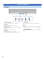
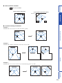
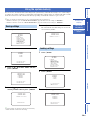
■ Ideal installation condition
■ For better listening environment
Example 1
Install this unit as close to the exact center of the wall as possible.
Example 2
Install this unit so that the sound beams can be reflected off the walls.
Example 3
Install this unit as close to the exact front of your normal listening position as possible.
: Object such as furniture
Parallel installation (with 5 Beam)
Corner installation (with Stereo+3Beam)
40° to 50°

12 En
■ Cables used for connections
The symbols on the left of cable names (such as , , and )
correspond with the symbols described in “Connecting your TV and
Blu-ray disc player” (page 12) and “Connecting audio video
components” (page 13).
For audio and video
HDMI cable
For audio
Audio pin cable (supplied)
Optical cable (supplied)
Digital audio pin cable (supplied)
For video
Video pin cable (supplied)
Component video pin cable
■ Information on HDMI
An HDMI cable can transmit both audio and video signals at the
same time. If your TV and other components have HDMI jacks, use
HDMI cables for simpler and easier connections.
See also: “Using the HDMI control function” (page 28), “INPUT
MENU” (page 35)
y
• This unit automatically converts input video signals and outputs the signals
from the HDMI OUT jack.
• The HDMI of this unit supports High-Bandwidth Digital Content Protection
(HDCP),
• We recommend that you use an HDMI cable shorter than 5 m (16 ft) with
the HDMI logo printed on it.
■ Priority order for audio input signals
When digital and analog audio signals are simultaneously input from
a single source component, this unit plays back digital audio signals
by priority. For example, if audio signals are input to the DIGITAL
IN (AUX 1) and AUDIO IN (AUX 1) jacks simultaneously, this unit
plays back audio signals input to the DIGITAL IN (AUX 1) jack
when “AUX1” is selected as the input source.
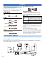
Connect external components (TV, Blu-ray disc player, etc.) to this unit. Do not plug the power supply cable into an AC wall outlet until all
connections are complete.
■ Connecting your TV and Blu-ray disc player
The following connection example shows a way to connect your TV and Blu-ray disc player by using the HDMI jacks. When you connect them
by using the other jacks, refer to “Connecting audio and video components” (page 13). The symbols beside the cables correspond with the
symbols described in “Cables used for connections” (page 12).
Connections
Before connecting components
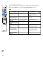
Input source Audio signal type
Blu-ray disc
HD DVD
Dolby Digital, Dolby Digital Plus, Dolby TrueHD,
DTS, DTS-HD High Resolution Audio, DTS-HD
Master Audio, 2-channel PCM, multi-channel PCM
DVD video Dolby Digital, DTS, 2-channel PCM, multi-channel
PCM
DVD audio 2-channel PCM, multi-channel PCM
Connecting external components
Optical digital
output
HDMI
output
HDMI
input
OUT
HDMI
IN 1
IN 2
IN 3
IN 4
AUX 1 TVAUX 2
DIGITAL IN
TV
Power cable
to AC wall outlet
1. Pull out the cap
(if attached)
2. Check the direction
Blu-ray disc player

13 En
PREPARATIONINTRODUCTION APPENDIXPLAYBACK FEATURES SETTINGS
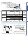
■ Connecting audio and video components
Determine the connection types depending on the jacks available on this unit and your external components. The symbols in the following table
correspond with the symbols described in “Cables used for connections” (page 12).
y
• Video signals input from the VIDEO IN (VIDEO) jack can be output not only to the VIDEO OUT jack but also the HDMI OUT jack. Video signals input from
the VIDEO IN (COMPONENT) jacks are output to the HDMI OUT jack.
Wireline connection
Connect the monaural input jack on your subwoofer to the
SUBWOOFER jack on this unit.
y
• If the subwoofer is connected by using a system type connection, changing
the power mode of this unit controls the power mode of the subwoofer
(Yamaha subwoofer).
Wireless connection
You can make a wireless connection of your subwoofer by using the
Yamaha wireless subwoofer kit (SWK-W10). About SWK-W10,
refer to “Safety and Accessory Information” (separate booklet).
See also: “WIRELESS SETUP” (page 36)
y
• For proper transmission, you need to set the group IDs of this unit and
SWK-W10 to the same value. For the Group ID settings, refer to “Group
ID” (page 36) and “Safety and Accessory Information (separate booklet)”.
Note
• Be sure to use the product only in the country in where it was purchased.
External component Signal type
Jacks to use
Cable to
use
Input selection
key
On external component On this unit
TV Video Composite video input VIDEO OUT
Audio Analog audio output AUDIO IN (TV) TV
External component
with HDMI output
Audio/video HDMI output HDMI IN 1-4 HDMI1-4
External component
with component video
output
Audio Coaxial digital output DIGITAL IN (AUX 2) AUX2
Video Component video output VIDEO IN (COMPONENT)
External component
with composite video
output
Audio Optical digital output DIGITAL IN (AUX 1) AUX1
Analog audio output AUDIO IN (AUX 1)
Video Composite video output VIDEO IN (VIDEO)
Connecting a subwoofer
AUX 1 TV
HDMI
AUX 2AUX 1 TVOUTIN
IR IN
SYSTEM
CONNECTOR
SUB
WOOFER
COMPONENT
DIGITAL INAUDI O INVIDEO
RS-232C
VIDEOVIDEO
Y
P
R PB
RR
LL
IN 1
IN 2
IN 3
IN 4
DIGITAL INAUDIO INVIDEO
VIDEO IN/OUT
jacks
AUDIO IN
jacks
DIGITAL IN
jacks
HDMI IN
jacks
AUX 1 TVAUX 2AUX 1 TVOUT
IR IN
SYSTEM
CONNECTOR
SUB
WOOFER
DIGITAL INAUDIO IN
RS-232C
Monaural input System connector
INPUT VOLUME INTELLIBEAM MIC
SWK-W10
Subwoofer

14 En
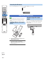
Connect the supplied FM antenna or your antenna to the FM ANTENNA jack on this unit.
Note
• Before installing batteries or using the remote control, make
sure that you read precautions on the remote control and
batteries in “Safety and Accessory Information” (separate
booklet).
1 Pull and hold the tab on the battery cover
and then open the cover.
2 Insert the two supplied batteries (R03P, UM4,
AAA) into the battery compartment.
Make sure you insert the batteries according to the
polarity markings (+/–).
3 Close the battery cover.
The remote control transmits a directional infrared beam.
Use the remote control within 6 m (20 ft) of this unit and
point it toward the remote control sensor of this unit
during operation.
Connecting the FM antenna
Preparing the remote control
FM ANTENNA
Antenna
Installing batteries in the remote
control
Pull and hold
Operation range of the remote
control
INPUT VOLUME INTELLIBEAM MIC
Within
6m (20ft)
30° 30°
0 +10
ENT
7 8 9
4 5 6
1 2 3
HDMI 4 iPod FM
ENTER
SURROUND STEREO
OFF
ENTER
TAINMENT
MUSIC
CINEMA DSP
MOVIE
HDMI 1 HDMI 2 HDMI 3
TV AUX 1 AUX 2
TV AV
MENUTOP MENU
OPTION
TV
MUTE
CODE SET
UNIVOLUME SUR. DECODE INTELLIBEAM
TV
INPUT MUTE
TV VOL CH VOLUME
SETUP RETURN
MEMORY
SLEEPINFO
TUNING PRESET
OPTION SETUP RETURN
I
ENTER
G
GENTER
G /
ISETUP

15 En
PREPARATIONINTRODUCTION APPENDIXPLAYBACK FEATURES
Changing OSD
language
AUTO SETUP
(IntelliBeam)
Using the system
memory
SETTINGS
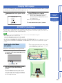
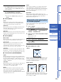
You can select an OSD language among English, German, French, Spanish, Italian, Dutch and Russian. Before operating
the following steps, select this unit as the video input on your TV.
1 Press and hold ISETUP until the
“LANGUAGE SETUP” menu appears on your
TV.
2 Press G / to select the desired
language and then press GENTER.
Choices: ENGLISH (English), DEUTSCH (German),
Français (French), ESPAÑOL (Spanish),
ITALIANO (Italian), NEDERLANDS (Dutch),
Русский (Russian)
Initial setting: ENGLISH (English)
3 To exit from the menu, press ISETUP.
This unit creates a sound field by reflecting sound beams off the walls of your listening room and by broadening the
cohesion of all the channels. Just as you would arrange the speaker position of other audio systems, you need to set the
beam angle to enjoy the best possible sound from this unit.
Notes
• After you have completed the AUTO SETUP procedure, be sure to disconnect the IntelliBeam microphone.
• The IntelliBeam microphone is sensitive to heat.
– Keep the IntelliBeam microphone away from direct sunlight.
– Do not place the IntelliBeam microphone on top of this unit.
• You cannot use the AUTO SETUP when “PREOUT” is selected in “SOUND OUT” (page 35).
• You cannot run the AUTO SETUP while playing back the iPod/iPhone by using PDX-50TX. To run the AUTO SETUP, stop playback
and then disconnect the iPod/iPhone from PDX-50TX. About PDX-50TX, refer to “Safety and Accessory Information” (separate
booklet).
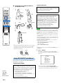
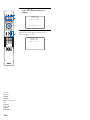
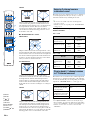
Follow the procedure below to connect the IntelliBeam
microphone to this unit and place it in a proper location.
1 Connect the supplied IntelliBeam
microphone to the INTELLIBEAM MIC jack on
the front panel.
2 Place the IntelliBeam microphone on a flat
level surface at your normal listening
position.
Place the IntelliBeam microphone on the extended
center line of this unit and 1.8 m (6.0 ft) or more
away from it. Also, make sure place the IntelliBeam
microphone within 1 m (3.3 ft) upper or lower from
the center height of this unit.
y
• Use the supplied cardboard microphone stand or a tripod
to place the IntelliBeam microphone at the same height as
your ears would be when you are seated.
Changing OSD language
ENGLISH
DEUTSCH
Francais
ESPANOL
ITALIANO
NEDERLANDS
[ ]/[ ]:Up/Down
[ENTER]:Enter
3)LANGUAGE SETUP
p
p
.
AUTO SETUP (IntelliBeam)
Installing the IntelliBeam
microphone
INPUT VOLUME INTELLIBEAM MIC
INTELLIBEAM MIC
IntelliBeam microphone
1.8 m (6.0 ft)
or more
Within 1 m (3.3 ft)
Cardboard
microphone stand
Listening
position
Upper limit
Lower limit
Center height of
this unit
Within 1 m (3.3 ft)
IntelliBeam
microphone
Cardboard
microphone
stand
Center line

16 En
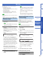
■ Assembling the supplied cardboard
microphone stand
y
• If a subwoofer with adjustable volume and crossover frequency
controls is connected to this unit, turn it on, set the volume to
about half way and then set the crossover frequency to the
maximum as shown below.
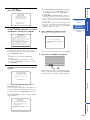
You can select one of the following AUTO SETUP types
depending on your purpose.
“BEAM+SOUND OPTIMZ”
“BEAM OPTIMZ ONLY”
“SOUND OPTIMZ ONLY”
Notes
• It is normal for loud test tones to be output during the AUTO
SETUP procedure. Make sure that there are no children around
in the listening room while the AUTO SETUP procedure is in
progress.
• Make sure that your listening room is as quiet as possible. For
accurate measurement, turn off air conditioner or other devices
that make noises.
• To achieve the best results possible, vacate your listening room
until the AUTO SETUP procedure is completed so that you may
not obstruct the path of sound beams.
• If there are curtains in your listening room, we recommend
following the procedure below.
1. Open the curtains to improve sound reflection.
2. Run “BEAM OPTIMZ ONLY”.
3. Close the curtains.
4. Run “SOUND OPTIMZ ONLY”.
y
• To return to the previous screen while using SET MENU, press
IRETURN.
1 Press ISETUP.
The remote control keys to be used and available
operations in each step are displayed at the bottom of
the screen.
y
• You can also start the “BEAM+SOUND OPTIMZ”
procedure simply by holding down MINTELLIBEAM for
more than two seconds. In this case, proceed to step 4.
Using AUTO SETUP (IntelliBeam)
(Beam optimization and sound optimization)
Use to optimize the beam angle, delay, volume, and
quality so that the parameters best match your listening
environment. It is recommended that you should select
this optimization feature in the following cases:
• If you make settings for the first time
• If the unit has been relocated
• If your listening room has been restructured
• If the objects in your listening room (furniture, etc.)
have been rearranged
This menu takes about three minutes.
12
34
5
Remove
Fit in
Fit in
Place horizontally
Run through
VOLUME
MIN MAX MIN
MAX
CROSSOVER
HIGH CUT
Subwoofer
(Beam optimization only)
Use to optimize the beam angle so that the parameter
best matches your listening environment.
This menu takes about one minute.
(Sound optimization only)
Use to optimize the beam delay, volume, and quality so
that the parameters best match your listening
environment. You must optimize the beam angle with
“BEAM OPTIMZ ONLY” before starting “SOUND
OPTIMZ ONLY”. It is recommended that you should
select this optimization feature in the following cases:
• If you have opened or closed the curtains in your
listening room before using this unit
• If you have manually set the beam angle.
This menu takes about three minutes.
;MEMORY
;AUTO SETUP
;MANUAL SETUP
;SOUND SET MENU
;SOUND OUT MENU
;INPUT MENU
;DISPLAY MENU
[ ]/[ ]:Up/Down
[ENTER]:Enter
SET MENU
.
p
p
0 +10
ENT
7 8 9
4 5 6
1 2 3
HDMI 4 iPod FM
ENTER
SURROUND STEREO
OFF
ENTER
TAINMENT
MUSIC
CINEMA DSP
MOVIE
HDMI 1 HDMI 2 HDMI 3
TV AUX 1 AUX 2
TV AV
MENUTOP MENU
OPTION
TV
MUTE
CODE SET
UNIVOLUME SUR. DECODE INTELLIBEAM
TV
INPUT MUTE
TV VOL CH VOLUME
SETUP RETURN
MEMORY
SLEEPINFO
TUNING PRESET
M
OPTION SETUP RETURN
I
ENTER
G
GENTER
G /
IRETURN
ISETUP
MINTELLIBEAM

17 En
PREPARATIONINTRODUCTION APPENDIXPLAYBACK FEATURES
Changing OSD
language
AUTO SETUP
(IntelliBeam)
Using the system
memory
SETTINGS
2 Press G / to select “AUTO SETUP” and
then press GENTER.
3 Press G / to select “BEAM+SOUND
OPTIMZ”, “BEAM OPTIMZ ONLY” or “SOUND
OPTIMZ ONLY” and then press GENTER.
4 Prepare to leave the room.
The best setting may not be done if you are in the
room. Prepare to leave the room in 10 seconds after
pressing GENTER in step 5.
y
• Wait outside the room during the AUTO SETUP
procedure.
• The AUTO SETUP procedure takes about 3 minutes.
• To cancel the AUTO SETUP procedure after it is started,
press IRETURN.
5 Press GENTER to start the AUTO SETUP
procedure and then leave the room within 10
seconds.
The setup screen automatically changes during the
AUTO SETUP procedure.
If an error occurs, an error buzzer sounds and an error
message is displayed. For details on error messages,
see “Error messages for AUTO SETUP” (page 18).
If the AUTO SETUP procedure is complete, this unit
rings the chimes.
y
• If “ENVIRONMENT CHECK [FAILED]” is displayed,
refer to “Error messages for AUTO SETUP” (page 18),
press IRETURN, and then run the AUTO SETUP
procedure again.
• If “SUBWOOFER :NOT APPLICABLE” is displayed
even though a subwoofer is connected to this unit and
turned on, check the connection and then increase the
volume level of the subwoofer and run the AUTO SETUP
procedure again.
• Depending on the environment of your listening room, the
beam angles of front right and left and surround left and
right may be set to the same value even if “BEAM MODE
:5 BEAM” is displayed as a result.
6 Press GENTER to confirm the results.
The menu screen disappears in two seconds.
y
• If you do not want to reflect the results, press IRETURN.
7 Disconnect the IntelliBeam microphone.
The measurement results are stored in the internal
memory of this unit until you run the AUTO SETUP
procedure again or configure the settings manually.
1)BEAM+SOUND OPTIMZ
2)BEAM OPTIMZ ONLY
3)SOUND OPTIMZ ONLY
[ ]/[ ]:Up/Down
[ENTER]:Enter
B)AUTO SETUP
p
p
PREPARATION & CHECK
Please connect the MIC.
Please place the MIC at least
1.8m/6ft away from the unit.
The MIC should be set
at ear level when seated.
Measurement takes about 3min.
After [ENTER] is pressed,
please leave the room.
[ENTER]:Start [RETURN]:Cancel
AUTO SETUP
Will begin in 10sec
Please leave the room
*--------
[RETURN]:Cancel
AUTO SETUP START
MEASUREMENT COMPLETE
BEAM MODE :5Beam/Plus2
SUBWOOFER :YES
[ENTER]:Save set-up.
[RETURN]:Do not save set-up.
XXXXXXXXSHOW RESULTXXXXXXXXXX
AUTO SETUP COMPLETE
Please remove the MIC from
the unit and the listening
position.
INPUT VOLUME INTELLIBEAM MIC

18 En
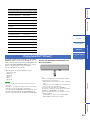
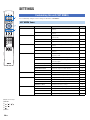
■ Error messages for AUTO SETUP
If an error message is displayed on your TV, check the error message list to solve the problem and then follow the
procedure below.
[ERROR E-1]: Press GENTER to run the AUTO SETUP procedure again or IRETURN to cancel the operation
Other errors: Press IRETURN to cancel the operation and then run the AUTO SETUP procedure again.
Note
If the problem is difficult to be solved, configure the settings manually in “MANUAL SETUP” (page 31).
Error message Cause Remedy
See
page
ERROR E-1
Please test in quieter environment.
There is too much unwanted noise in
your listening room.
Make sure that your listening room is as
quiet as possible. You may want to
choose certain hours during the day
when there is not much noise coming
from outside.
—
ERROR E-2
No MIC detected. Please check
MIC connection and re-try.
The IntelliBeam microphone is not
connected to this unit or disconnected
during the AUTO SETUP procedure.
Connect the IntelliBeam microphone to
this unit firmly.
15
ERROR E-3
Unexpected control is detected.
Please re-try.
Some other operations were performed
on this unit while the AUTO SETUP
procedure was in progress.
Do not perform any other operations
while the AUTO SETUP procedure is in
progress.
—
ERROR E-4
Please check MIC position. MIC
should be set in front of the unit
and re-try.
The IntelliBeam microphone is not
placed in front of this unit.
Make sure that the IntelliBeam
microphone is installed in front of this
unit.
15
ERROR E-5
Please check MIC position. MIC
should be set above 1.8m/6.0ft and
re-try.
The IntelliBeam microphone is not
placed in the right distance from this
unit.
Make sure that the IntelliBeam
microphone is installed more than 1.8 m
(6.0 ft) from the front of this unit and
within 1 m (3.3 ft) from the center height
of this unit.
15
ERROR E-6
Volume level is lower than
expected. Please check MIC
position/connection and re-try.
The IntelliBeam microphone cannot
collect the sound produced by this unit
because the sound output level is too low.
Make sure that the IntelliBeam
microphone is firmly connected to this
unit and placed in a proper location. If
the problem persists, contact the nearest
authorized Yamaha service center for
assistance.
15
ERROR E-7
Unexpected error happened.
Please re-try.
An internal system error occurred. Repeat the AUTO SETUP procedure.
—
0 +10
ENT
7 8 9
4 5 6
1 2 3
HDMI 4 iPod FM
ENTER
SURROUND STEREO
OFF
ENTER
TAINMENT
MUSIC
CINEMA DSP
MOVIE
HDMI 1 HDMI 2 HDMI 3
TV AUX 1 AUX 2
TV AV
MENUTOP MENU
OPTION
TV
MUTE
CODE SET
UNIVOLUME SUR. DECODE INTELLIBEAM
TV
INPUT MUTE
TV VOL CH VOLUME
SETUP RETURN
MEMORY
SLEEPINFO
TUNING PRESET
OPTION SETUP RETURN
I
ENTER
G
GENTER
G /
IRETURN
ISETUP

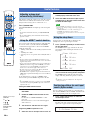
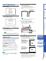
19 En
PREPARATIONINTRODUCTION APPENDIXPLAYBACK FEATURES
Changing OSD
language
AUTO SETUP
(IntelliBeam)
Using the system
memory
SETTINGS
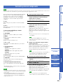
You can save the current beam and sound settings in the system memory of this unit. It is handy to save certain settings
according to the varying conditions of your listening environment. For example, if there are curtains in the path of sound
beams, the effectiveness of the sound beams will vary depending on whether the curtains are open or closed.
y
• If there are curtains in your listening room, we recommend following the procedure below.
1. While the curtains are open, run “BEAM+SOUND OPTIMZ” (page 16) and then save the settings to “MEMORY1”.
2. While the curtains are closed, run “SOUND OPTIMZ ONLY” (page 16) and then save the settings to “MEMORY2”.
1 Press ISETUP.
2 Press GENTER.
3 Press G / to select “SAVE” and then
press GENTER.
4 Press G / to select the desired
memory number and then press GENTER.
y
• If system settings are already stored in the selected memory
number, this unit overwrites the old settings.
5 Press GENTER.
The current beam and sound settings are saved to the
selected memory number.
1 Press ISETUP.
2 Press GENTER.
3 Press GENTER again.
Using the system memory
Saving settings
;MEMORY
;AUTO SETUP
;MANUAL SETUP
;SOUND SET MENU
;SOUND OUT MENU
;INPUT MENU
;DISPLAY MENU
[ ]/[ ]:Up/Down
[ENTER]:Enter
SET MENU
.
p
p
1)LOAD
2)SAVE
[ ]/[ ]:Up/Down
[ENTER]:Enter
A)MEMORY
p
p
a)MEMORY1
b)MEMORY2
c)MEMORY3
[ ]/[ ]:Up/Down
[ENTER]:Enter
2)MEMORY SAVE
p
p
MEMORY1 Save Now?
[ENTER]:Enter
2)MEMORY SAVE
Loading settings
MEMORY1 Saving...
2)MEMORY SAVE
;MEMORY
;AUTO SETUP
;MANUAL SETUP
;SOUND SET MENU
;SOUND OUT MENU
;INPUT MENU
;DISPLAY MENU
[ ]/[ ]:Up/Down
[ENTER]:Enter
SET MENU
.
p
p
1)LOAD
2)SAVE
[ ]/[ ]:Up/Down
[ENTER]:Enter
A)MEMORY
p
p
a)MEMORY1
b)MEMORY2
c)MEMORY3
[ ]/[ ]:Up/Down
[ENTER]:Enter
1)MEMORY LOAD
p
p

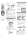
20 En
4 Press G / to select the memory
number to be loaded and then press
GENTER.
5 Press GENTER.
The beam and sound settings saved in the selected
memory number are loaded.
MEMORY1 Load Now ?
Push [ENTER] to Load
1)MEMORY LOAD
MEMORY1 Loading...
1)MEMORY LOAD
0 +10
ENT
7 8 9
4 5 6
1 2 3
HDMI 4 iPod FM
ENTER
SURROUND STEREO
OFF
ENTER
TAINMENT
MUSIC
CINEMA DSP
MOVIE
HDMI 1 HDMI 2 HDMI 3
TV AUX 1 AUX 2
TV AV
MENUTOP MENU
OPTION
TV
MUTE
CODE SET
UNIVOLUME SUR. DECODE INTELLIBEAM
TV
INPUT MUTE
TV VOL CH VOLUME
SETUP RETURN
MEMORY
SLEEPINFO
TUNING PRESET
ENTER
G
C
MUTE
K
HDMI 4 iPod
HDMI 1 HDMI 2 HDMI 3
TV AUX 1 AUX 2
D
FM
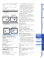
CPower
DAUX1/2
DHDMI1
DHDMI1-4
DInput selector keys
DTV
GENTER
G /
KMUTE
KVOLUME +/–
Pagina se încarcă...
Pagina se încarcă...
Pagina se încarcă...
Pagina se încarcă...
Pagina se încarcă...
Pagina se încarcă...
Pagina se încarcă...
Pagina se încarcă...
Pagina se încarcă...
Pagina se încarcă...
Pagina se încarcă...
Pagina se încarcă...
Pagina se încarcă...
Pagina se încarcă...
Pagina se încarcă...
Pagina se încarcă...
Pagina se încarcă...
Pagina se încarcă...
Pagina se încarcă...
Pagina se încarcă...
Pagina se încarcă...
Pagina se încarcă...
Pagina se încarcă...
Pagina se încarcă...
Pagina se încarcă...
Pagina se încarcă...
Pagina se încarcă...
Pagina se încarcă...
Pagina se încarcă...
Pagina se încarcă...
Pagina se încarcă...
Pagina se încarcă...
Pagina se încarcă...
Pagina se încarcă...
-
 1
1
-
 2
2
-
 3
3
-
 4
4
-
 5
5
-
 6
6
-
 7
7
-
 8
8
-
 9
9
-
 10
10
-
 11
11
-
 12
12
-
 13
13
-
 14
14
-
 15
15
-
 16
16
-
 17
17
-
 18
18
-
 19
19
-
 20
20
-
 21
21
-
 22
22
-
 23
23
-
 24
24
-
 25
25
-
 26
26
-
 27
27
-
 28
28
-
 29
29
-
 30
30
-
 31
31
-
 32
32
-
 33
33
-
 34
34
-
 35
35
-
 36
36
-
 37
37
-
 38
38
-
 39
39
-
 40
40
-
 41
41
-
 42
42
-
 43
43
-
 44
44
-
 45
45
-
 46
46
-
 47
47
-
 48
48
-
 49
49
-
 50
50
-
 51
51
-
 52
52
-
 53
53
-
 54
54


Yamaha YSP-4100 Manual de utilizare
- Categorie
- Receptor
- Tip
- Manual de utilizare
în alte limbi
- Türkçe: Yamaha YSP-4100 Kullanım kılavuzu
- français: Yamaha YSP-4100 Manuel utilisateur
- русский: Yamaha YSP-4100 Руководство пользователя
- English: Yamaha YSP-4100 User manual
- suomi: Yamaha YSP-4100 Ohjekirja
- Deutsch: Yamaha YSP-4100 Benutzerhandbuch
- italiano: Yamaha YSP-4100 Manuale utente
- español: Yamaha YSP-4100 Manual de usuario
- svenska: Yamaha YSP-4100 Användarmanual
- dansk: Yamaha YSP-4100 Brugermanual
- português: Yamaha YSP-4100 Manual do usuário
- Nederlands: Yamaha YSP-4100 Handleiding
Lucrări înrudite
-
Yamaha YSP-CU2200 Manual de utilizare
-
Yamaha YHT-S401 Manualul proprietarului
-
Yamaha YRS-700 Manualul proprietarului
-
Yamaha YSP-3000 Manualul proprietarului
-
-
Yamaha YRS-1100 Manualul proprietarului
-
Yamaha YSP-4000 Manualul proprietarului
-
Yamaha YHT-S300 Manualul proprietarului
-
-
