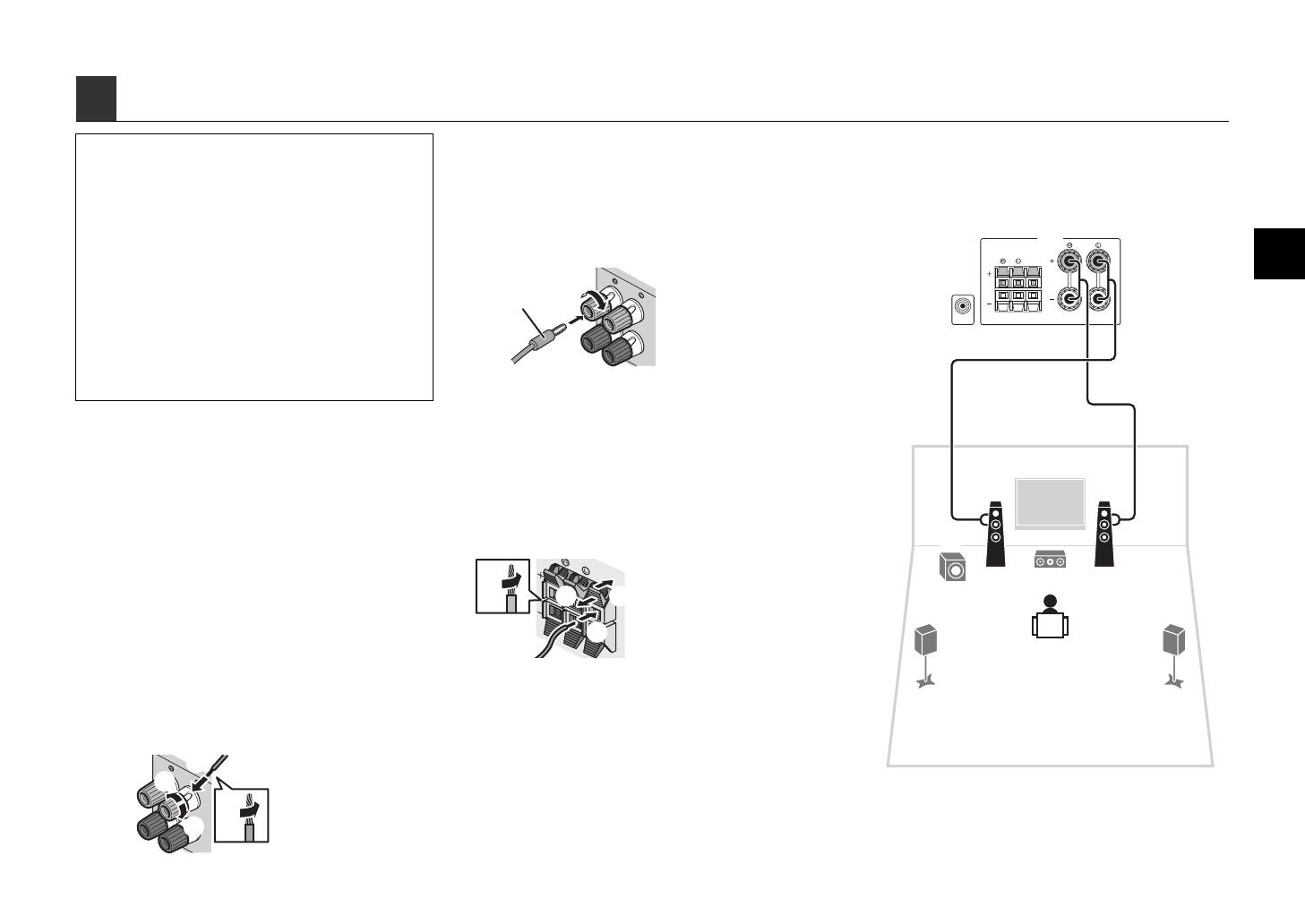
Yamaha HTR-3065 Manualul utilizatorului

Categorie
Receptoare AV
Tip
Manualul utilizatorului
English
Français
Deutsch
Svenska
Italiano
Español
Nederlands
AV Receiver/Ampli-tuner audio-vidéo
G
Easy Setup Guide
Manuel de configuration rapide
Anleitung zur Schnelleinrichtung
Snabbinstallationsguide
Guida di configurazione rapida
Guía de configuración sencilla
Easy Setup-gids
En 1
Check that the following accessories are supplied with the product.
The following cables (not supplied) are required to build the system described in this
document.
Speaker cables (x5)
HDMI cable (x2)
Audio pin cable (x1)
Digital optical cable (x1)
(not required if your TV supports ARC [Audio Return Channel])
1 Preparation
Accessories
Remote control Batteries
(AAA, R03, UM-4) (x2)
Insert the batteries the right way round.
AM antenna FM antenna YPAO microphone
CD-ROM
(Owner’s Manual)
Safety Brochure Easy Setup Guide
The illustrations of the remote control used in this guide are of the U.S.A. model.
(Australia model only)
For information on how to control external devices with the remote control, refer to “Supplement for
Remote Control” on the supplied CD-ROM.
Cables required for connections
*The supplied FM antenna
varies depending on the
region of purchase.
Easy Setup Guide
English
AV Receiver
This document explains how to set up a 5.1-channel system
and play back surround sound from a BD/DVD on the unit.
To reduce the impact on natural resources, the Owner's Manual for this product
is supplied on CD-ROM. For more information about this product, refer to the
Owner's Manual on the supplied CD-ROM.
PDF versions of this guide and “Owners Manual” can be downloaded from the
following website.
http://download.yamaha.com/
HTR-3065_esg_C.fm Page 1 Wednesday, December 21, 2011 4:01 PM
2 En
Set up the speakers in the room using the following diagram as a reference.
For information on other speaker systems, refer to “Owner’s Manual”.
2 Placing speakers
12
3
45
9
1 Front speaker (L)
2 Front speaker (R)
3 Center speaker
4 Surround speaker (L)
5 Surround speaker (R)
9 Subwoofer
10° to 30°10° to 30°
HTR-3065_esg_C.fm Page 2 Wednesday, December 21, 2011 4:01 PM
En 3
Connecting speaker cables
Speaker cables have two wires. One is for connecting
the negative (-) terminals of the unit and the speaker,
and the other is for the positive (+) terminals. If the wires
are colored to prevent confusion, connect the black wire
to the negative and the other wire to the positive
terminals.
(Connecting front speakers)
a Remove approximately 10 mm (3/8”) of insulation from
the ends of the speaker cable and twist the bare wires of
the cable firmly together.
b Loosen the speaker terminal.
c Insert the bare wires of the cable into the gap on the side
(upper right or bottom left) of the terminal.
d Tighten the terminal.
Using a banana plug
(U.S.A., Canada, Australia and General models only)
a Tighten the speaker terminal.
b Insert a banana plug into the end of the terminal.
(Connecting center/surround speakers)
a Remove approximately 10 mm (3/8”) of insulation from
the ends of the speaker cable and twist the bare wires of
the cable firmly together.
b Press down the tab.
c Insert the bare wires of the cable into the hole in the
terminal.
d Release the tab.
1
Connect the front speakers (1/2)
to the FRONT (//\) terminals.
3 Connecting speakers/subwoofer
(U.S.A. and Canada models only)
Under its default settings, the unit is configured for 8-ohm
speakers. When connecting 6-ohm speakers, set the unit’s
speaker impedance to “6 Ω MIN”. For details, see “Setting the
speaker impedance” in “Owner’s Manual”.
Use a subwoofer equipped with built-in amplifier.
Before connecting the speakers, remove the unit’s power cable
from the AC wall outlet and turn off the subwoofer.
Ensure that the core wires of the speaker cable do not touch
each other or come into contact with the unit’s metal areas. This
may damage the unit or the speakers. If the speaker cables
short circuit, “Check SP Wires” will appear on the front display
when the unit is turned on.
FRONT
aa
b
d
c
- (black)
+ (red)
F
RON
T
a
b
Banana plug
RO
U
ND
CENTER
aa
b
c
d
+ (red)
- (black)
FRONT
SURROUND
SUBWOOFER
CENTER
SPEAKERS
12
3
45
9
The unit (rear)
HTR-3065_esg_C.fm Page 3 Wednesday, December 21, 2011 4:01 PM
4 En
2
Connect the center speaker (3) to the
CENTER terminal.
3
Connect the surround speakers
(4/5) to the SURROUND (//\)
terminals.
4
Connect the subwoofer (9) to the
SUBWOOFER jack.
FRONT
SURROUND
SUBWOOFER
CENTER
SPEAKERS
12
3
45
9
The unit (rear)
FRONT
SURROUND
SUBWOOFER
CENTER
SPEAKERS
12
3
45
9
The unit (rear)
FRONT
SURROUND
SUBWOOFER
CENTER
SPEAKERS
12
3
45
9
The unit (rear)
Audio pin cable
HTR-3065_esg_C.fm Page 4 Wednesday, December 21, 2011 4:01 PM
En 5
4 Connecting external devices
FRONT
A
V
1
A
V
2
A
V
3
A
V
5
OPTICAL COAXIAL COAXIAL OPTICAL
(
TV
)
(
CD
)
COMPONENT
VIDEO
P
B
Y
VIDEO
AUD
IO 1
AUD
IO 2
AV
MONITOR OUT
OUT
OUT
AUDIO
A
V
4
COMPONENT
VIDEO
MONITOR OUT
P
R
P
B
Y
P
R
HDMI 1
(
BD/DVD
)
HDMI 2 HDMI 3
HDMI 4
HDMI
OUT
ARC
FM
ANTENNA
AM
SURROUND
SUBWOOFER
CENTER
SPEAKERS
YPAO MIC
INFO
MEMORY
PRESET
FM AM
TUNING
PHONES
SILENT
CINEMA
VIDEO
VOLU ME
AUX USB
TONE
CONTROL
STRAIGHT
TV
BD
DVD
CD
RADIO
INPUT
PROGRAM
SCENE
VIDEO
iPod/iPhone 5V 1A
AUDIO
HDMIOPTICAL
HDMI
HDMI
HDMI
OUT
ARC
HDMI HDMI
HDMI
a
b
c
O
OPTICAL
d
HDMI 1
(
BD/DVD
)
O
VOLTAGE
SELECTOR
110 V
-
120V
220V
-
240V
(
TV
)
AV 4
TV
Audio out
(optical)
HDMI in HDMI out
BD/DVD player
HDMI OUT
jack
HDMI 1 jack
AV 4 (OPTICAL) jack
The unit (rear)
To an AC wall
outlet
Turn on the unit
The unit (front)
VOLTAGE SELECTOR
(General model only)
1
Connect external devices to the unit.
a Connect a BD/DVD player to the unit with an HDMI
cable.
If the BD/DVD player is currently connected to the
TV directly with an HDMI cable, disconnect the
cable from the TV and connect it to this unit.
b Connect a TV to the unit with the other HDMI cable.
c Connect a TV to the unit with a digital optical cable.
This connection is required to play back TV audio
on the unit. This connection is not required if your
TV supports ARC (Audio Return Channel).
d Connect the power cable to an AC wall outlet.
For information on how to connect radio antennas or other
external devices, see “PREPARATIONS” in “Owner’s Manual”.
2
Turn on the unit, the TV and the BD/DVD
player.
3
Use the TV remote control to change the
TV input to video from the unit.
The connections are complete. Proceed to the next
page to optimize the speaker settings.
By connecting a TV to the unit with an HDMI cable, you can
configure the unit’s settings with the menu displayed on the TV. In
addition, you can select the on-screen menu language from English
(default), French, German, Spanish, Russian and Chinese. For
details, refer to “Owner’s Manual”. In this guide, illustrations of
English menu screens are used as examples.
Before connecting the power cable (General model only)
Make sure you set the switch position of
VOLTAGE SELECTOR according to your local voltage.
Voltages are AC 110-120/220-240 V, 50/60 Hz.
HTR-3065_esg_C.fm Page 5 Wednesday, December 21, 2011 4:01 PM
6 En
The Yamaha Parametric room Acoustic Optimizer (YPAO) function detects speaker connections, measures the
distances from them to your listening position(s), and then automatically optimizes the speaker settings, such as
volume balance and acoustic parameters, to suit your room.
Preparing for YPAO
5
Optimizing the speaker settings automatically (YPAO)
During the measuring process, test tones are output at high volume. Ensure that
the test tones do not frighten small children. Also, refrain from using this function at
night when it may be a nuisance to others.
During the measuring process, you cannot adjust the volume.
During the measuring process, keep the room as quiet as possible.
Do not connect headphones.
Do not stand between the speakers and the YPAO microphone during the
measurement process (about 3 minutes).
Move to the corner of the room or leave the room.
1
Connect the YPAO microphone to the
YPAO MIC jack on the front panel.
The following screen appears.
To cancel the operation, disconnect the YPAO microphone, or
use the cursor keys to select “Exit” and press ENTER, before
starting the measurement.
2
To start the measurement, press SETUP.
The measurement will start in 10 seconds.
The following screen appears on the TV when
the measurement finishes.
Auto Setup
Start
Exit
Press SETUP key
to Start
VOL.
SW
L
SL
C
SR
R
[SETUP]:Start
Auto Setup
Start
Exit
Measurement
Finished
Result
3 / 2 / 0.1 ch
3.0 / 10.5 m
-3.0 / 10.0 dB
VOL.
SW
L
SL
C
SR
R
Finished
VOLUME HIGH CUT
CROSSOVER/
MIN MAXMIN MAX
1234
1234
512
FM
INFO
MEMORY
AM
PRESET
TUNING
SCENE
OPTION
SETUP
RETURN
VOLUME
BD
DVD
TV
CD
RADIO
MUTE
ENTER
TRANSMIT
RECEIVER
HDMI
AV
AUDIO
TUNER
SLEEP
USB
MODE
V-AUX
MOVIE MUSIC
SUR. DECODE STRAIGHT
ENHANCER
2
1 4
3
2
1
4
3
1
2
FM
I
NF
O
MEM
O
RY
AM
P
RESE
T
T
UNIN
G
S
CE
N
E
O
PTI
O
N
RET
UR
N
V
O
L
U
M
E
BD
DV
D
T
V
C
D
R
AD
I
O
MU
T
E
T
RAN
S
MI
T
RECEIVER
HDM
I
AV
AUDI
O
TUNER
S
LEEP
US
B
M
O
DE
V-
AU
X
MOVIE MUSI
C
S
UR. DECOD
E
S
TRAIGHT
E
NHAN
C
E
R
The unit (front)
Place the YPAO microphone at your
listening position (same height as your
ears). We recommend the use of a
tripod as a microphone stand. You can
use the tripod screws to fix the
microphone in place.
YPAO microphone
Listening position
Ear height
Cursor keys
ENTER
Turn on the subwoofer and set
the volume to half. If the
cross-over frequency is
adjustable, set it to maximum.
SETUP
HTR-3065_esg_C.fm Page 6 Wednesday, December 21, 2011 4:01 PM
En 7
If any error message (such as E-1) or warning message (such
as W-2) appears, see “Error messages” or “Warning
messages” in “Owner’s Manual”.
If the warning message “W-1:Out of Phase” appears, see “If
“W-1:Out of Phase” appears”.
3
Use the cursor keys to select “SAVE”
(Save) and press ENTER.
4
Disconnect the YPAO microphone from the
unit.
This completes optimization of the speaker settings.
Follow the procedure below to check the speaker
connections.
Depending on the type of speakers or room
environment, this message may appear even if the
speakers are connected correctly.
a Check for the blinking of the front display’s indicator to
identify the problem speaker.
b Check the cable connections (+/-) of the problem
speaker.
If the speaker is connected correctly:
You can save the current settings.
Proceed to step 3.
If the speaker is connected incorrectly:
Turn off the unit, reconnect the speaker cable, and then
try YPAO measurement again.
The YPAO microphone is sensitive to heat, so should not be
placed anywhere where it could be exposed to direct sunlight or
high temperatures (such as on top of AV equipment).
Auto Setup
Start
Exit
Measurement
Finished
Result
3 / 2 / 0.1 ch
3.0 / 10.5 m
-3.0 / 10.0 dB
SAVE
VOL.
SW
L
SL
C
SR
R
>SaveCancel
If “W-1:Out of Phase” appears
Warning
message
Auto Setup
Start
Exit
Measurement
Finished
Result
3 / 2 / 0.1 ch
3.0 / 10.5 m
-3.0 / 10.0 dB
W-1:Out of Phase
VOL.
SW
L
SL
C
SR
R
W-1:PHASE
Problem speaker (blinks)
HTR-3065_esg_C.fm Page 7 Wednesday, December 21, 2011 4:01 PM
8 En
Now let’s play back a BD/DVD.
We recommend playing back multichannel audio
(5.1-channel or more) to feel surround sound produced
by the unit.
1
Press HDMI 1 to select “HDMI 1” as the
input source.
2
Start playback on the BD/DVD player.
3
Press STRAIGHT repeatedly to select
STRAIGHT”.
When “STRAIGHT” (straight decode) is enabled, each
speaker produces each channel audio signal directly (without
sound field processing).
4
Press VOLUME to adjust the volume.
This completes the basic setup procedure.
Sound is only being output from the front speakers
during multichannel audio playback
Check the digital audio output setting on the BD/DVD
player.
It may be set to 2-channel output (such as PCM).
No sound is coming from a specific speaker
See “Troubleshooting” in “Owner’s Manual”.
6 Playing back a BD/DVD
1234
1234
512
FM
INFO
MEMORY
AM
PRESET
TUNING
SCENE
OPTION
SETUP
RETURN
VOLUME
BD
DVD
TV
CD
RADIO
MUTE
ENTER
TRANSMIT
RECEIVER
HDMI
AV
AUDIO
TUNER
SLEEP
USB
MODE
V-AUX
MOVIE MUSIC
SUR. DECODE STRAIGHT
ENHANCER
2
4
3
2
1
4
3
1
2
FM
I
NF
O
MEM
O
RY
AM
P
RESE
T
T
UNIN
G
S
CE
N
E
O
PTI
O
N
S
ET
U
P
RET
UR
N
BD
DV
D
T
V
C
D
R
AD
I
O
MU
T
E
ENTE
R
T
RAN
S
MI
T
RECEIVER
HDM
I
AV
AUDI
O
TUNER
S
LEEP
US
B
M
O
DE
V-
AU
X
MOVIE MUSIC
S
UR. DECOD
E
E
NHAN
C
E
R
HDMI 1
STRAIGHT
VOLUME
If surround sound is not working
SW
C
L
SL SR
R
HDMI1
VOL.
SW
C
L
SL
SR
R
VOL.
STRAIGHT
SW
C
L
SL SR
R
Volume -30.0dB
VOL.
Many more features!
The unit has various other functions.
Please refer to “Owner’s Manual” on the supplied
CD-ROM to help you get the most out of the unit.
Connecting other playback
devices
Connect audio devices (such as CD player),
game consoles, camcorders, and many others.
Selecting the sound mode
Select the desired sound program (CINEMA
DSP) or surround decoder suitable for movies,
music, games, sports programs, and other
uses.
Playing back from iPod
By using a USB cable supplied with iPod, you
can enjoy iPod music on the unit.
Listening to FM/AM radio
Playing back music stored on
a USB storage device
For more information, see “What you can do
with the unit”.
HTR-3065_esg_C.fm Page 8 Wednesday, December 21, 2011 4:01 PM
Fr 1
Vérifiez que les accessoires suivants sont fournis avec le produit.
Les câbles suivants (non fournis) sont requis pour l’installation du système décrit dans
le présent document.
Câbles d’enceinte (x5)
Câble HDMI (x2)
Câble de broche audio (x1)
Câble optique numérique (x1)
(inutile si votre téléviseur prend en charge la fonction ARC
[Audio Return Channel
])
1 Préparation
Accessoires
Télécommande Piles
(AAA, R03, UM-4) (x2)
Insérez les piles comme indiqué.
Antenne AM Antenne FM Microphone YPAO
CD-ROM
(Mode d’emploi)
Brochure sur la sécurité Manuel de configuration
rapide
Les illustrations de la télécommande de ce guide utilisent le modèle pour les États-Unis.
(Modèle pour l’Australie uniquement)
Pour plus d’informations sur l’utilisation de la télécommande pour commander des appareils externes,
reportez-vous au document « Supplement for Remote Control » du CD-ROM fourni.
Câbles requis pour les raccordements
* L’antenne FM fournie
dépend de la région
d’achat.
Manuel de
configuration rapide
Français
Ampli-tuner audio-vidéo
Ce document décrit la configuration d’un système à 5.1 voies et
explique comment restituer le son d’ambiance d’un disque BD/DVD
sur l’unité.
À des fins de protection de l’environnement, le Mode d’emploi de ce produit est fourni sur
CD-ROM. Pour plus d’informations sur ce produit, reportez-vous au Mode d’emploi sur
le CD-ROM fourni.
Pour télécharger ce guide ainsi que le « Mode d’emploi » au format PDF, rendez-vous sur le site Web
suivant :
http://download.yamaha.com/
HTR-3065_esg_G..fm Page 1 Friday, January 20, 2012 10:12 AM
2 Fr
Installez les enceintes dans la pièce en vous reportant au diagramme suivant.
Pour obtenir des informations sur les autres systèmes d’enceinte, consultez le « Mode d’emploi ».
2 Installation des enceintes
12
3
45
9
1 Enceinte avant (G)
2 Enceinte avant (D)
3 Enceinte centrale
4 Enceinte Surround (G)
5 Enceinte Surround (D)
9 Subwoofer
10° à 30°10° à 30°
HTR-3065_esg_G..fm Page 2 Friday, January 20, 2012 10:12 AM
Fr 3
Raccordement des câbles d’enceinte
Les câbles d’enceinte sont composés de deux fils. L’un
se connecte aux bornes négatives « - » de l’unité et de
l’enceinte, l’autre est destiné aux bornes positives « + ».
Si les fils sont de couleurs différentes afin d’éviter toute
confusion, connectez le fil de couleur noire aux bornes
négatives et l’autre fil aux bornes positives.
(Raccordement des enceintes avant)
a Dénudez sur environ 10 mm les extrémités du câble
d’enceinte et torsadez solidement les fils dénudés de
ce câble.
b Desserrez la borne d’enceinte.
c Insérez les fils dénudés du câble dans l’écartement sur le
côté (supérieur droit ou inférieur gauche) de la borne.
d Serrez la borne.
Utilisation d’une fiche banane
(Modèles pour les États-Unis, le Canada, l’Australie et
modèles standard uniquement)
a Serrez la borne d’enceinte.
b Insérez la fiche banane dans l’extrémité de la borne.
(Raccordement des enceintes centrale/surround)
a Dénudez sur environ 10 mm les extrémités du câble
d’enceinte et torsadez solidement les fils dénudés de
ce câble.
b Appuyez sur le levier.
c Insérez les fils dénudés du câble dans l’écartement de la
borne.
d Relâchez le levier.
1
Raccordez les enceintes avant (1/
2) aux bornes FRONT (//\).
3 Raccordement des enceintes/du caisson de graves
(Modèles pour les États-Unis et le Canada uniquement)
L’unité est configurée pour des enceintes 8 ohms par défaut.
Lorsque vous raccordez des enceintes 6 ohms, réglez
l’impédance d’enceinte de l’unité sur « 6 Ω MIN ». Pour plus
d’informations, reportez-vous à la section « Réglage de
l’impédance des enceintes » du « Mode d’emploi ».
Utilisez un caisson de graves équipé d’un amplificateur intégré.
Avant de raccorder les enceintes, retirez le câble d’alimentation
de l’unité de la prise secteur et éteignez le caisson de graves.
Veillez à ce que les fils conducteurs du câble de l’enceinte ne
se touchent pas ou n’entrent pas en contact avec les parties
métalliques de l’unité. Ce contact risque d’endommager l’unité
ou les enceintes. Si un court-circuit survient au niveau des
câbles de l’enceinte, le message « Check SP Wires » apparaît
sur l’afficheur de la face avant lors de la mise sous tension de
l’unité.
FRONT
aa
b
d
c
- (noir)
+ (rouge)
F
RON
T
a
b
Fiche banane
RO
U
ND
CENTER
aa
b
c
d
+ (rouge)
- (noir)
FRONT
SURROUND
SUBWOOFER
CENTER
SPEAKERS
12
3
45
9
L’unité (arrière)
HTR-3065_esg_G..fm Page 3 Friday, January 20, 2012 10:12 AM
4 Fr
2
Raccordez l’enceinte centrale (3)
à la borne CENTER.
3
Raccordez les enceintes d’ambiance
(4/5) aux bornes
SURROUND (//\).
4
Raccordez le caisson de graves (9)
à la prise SUBWOOFER.
FRONT
SURROUND
SUBWOOFER
CENTER
SPEAKERS
12
3
45
9
L’unité (arrière)
FRONT
SURROUND
SUBWOOFER
CENTER
SPEAKERS
12
3
45
9
L’unité (arrière)
FRONT
SURROUND
SUBWOOFER
CENTER
SPEAKERS
12
3
45
9
L’unité (arrière)
Câble de broche audio
HTR-3065_esg_G..fm Page 4 Friday, January 20, 2012 10:12 AM
Fr 5
4 Raccordement des appareils externes
FRONT
A
V
1
A
V
2
A
V
3
A
V
5
OPTICAL COAXIAL COAXIAL OPTICAL
(
TV
)
(
CD
)
COMPONENT
VIDEO
P
B
Y
VIDEO
AUD
IO 1
AUD
IO 2
AV
MONITOR OUT
OUT
OUT
AUDIO
A
V
4
COMPONENT
VIDEO
MONITOR OUT
P
R
P
B
Y
P
R
HDMI 1
(
BD/DVD
)
HDMI 2 HDMI 3
HDMI 4
HDMI
OUT
ARC
FM
ANTENNA
AM
SURROUND
SUBWOOFER
CENTER
SPEAKERS
YPAO MIC
INFO
MEMORY
PRESET
FM AM
TUNING
PHONES
SILENT
CINEMA
VIDEO
VOLU ME
AUX USB
TONE
CONTROL
STRAIGHT
TV
BD
DVD
CD
RADIO
INPUT
PROGRAM
SCENE
VIDEO
iPod/iPhone 5V 1A
AUDIO
HDMIOPTICAL
HDMI
HDMI
HDMI
OUT
ARC
HDMI HDMI
HDMI
a
b
c
O
OPTICAL
d
HDMI 1
(
BD/DVD
)
O
VOLTAGE
SELECTOR
110 V
-
120V
220V
-
240V
(
TV
)
AV 4
Téléviseur
Sortie audio
(optique)
Entrée HDMI Sortie HDMI
Lecteur BD/DVD
Prise
HDMI OUT
Prise HDMI 1
Prise AV 4 (OPTICAL)
L’unité (arrière)
Branchement
sur une prise
secteur
Mettre l’unité
sous tension
L’unité (avant)
VOLTAGE SELECTOR
(Modèles Standard
uniquement)
1
Raccordez les appareils externes à l’unité.
a Raccordez un lecteur BD/DVD à l’unité au moyen
d’un câble HDMI.
Si le lecteur BD/DVD est actuellement directement
raccordé au téléviseur à l’aide d’un câble HDMI,
débranchez ce câble du téléviseur et raccordez-le
à cette unité.
b Raccordez un téléviseur à l’unité au moyen de
l’autre câble HDMI.
c Raccordez un téléviseur à l’unité au moyen d’un
câble optique numérique.
Ce raccordement est nécessaire si vous souhaitez
restituer le son TV sur l’unité. Ce raccordement
n’est pas nécessaire si votre téléviseur prend en
charge la fonction ARC (Audio Return Channel).
d Raccordez le câble d’alimentation à une prise
électrique murale.
Pour plus d’informations sur le raccordement des antennes
radio ou des autres appareils externes, reportez-vous à la
section « PRÉPARATION » du « Mode d’emploi ».
2
Mettez sous tension, l’unité, le téléviseur
et le lecteur BD/DVD.
3
Utilisez la télécommande du téléviseur pour
changer la source d’entrée du téléviseur et
afficher l’image à partir de l’unité.
Les raccordements sont terminés. Passez à la page
suivante pour optimiser les réglages des enceintes.
Lorsque vous utilisez un câble HDMI pour raccorder le téléviseur
à l’unité, vous pouvez configurer les réglages de cette dernière
à l’aide du menu qui s’affiche sur le téléviseur. Par ailleurs, vous
pouvez sélectionner la langue souhaitée dans le menu affiché
à l’écran parmi les langues suivantes : allemand, anglais (par
défaut), chinois, espagnol, français et russe. Pour plus d’informations,
reportez-vous au « Mode d’emploi ». Des illustrations d’écrans de
menus anglais sont utilisées comme exemples dans ce guide.
Avant de raccorder le câble d’alimentation (modèle
standard uniquement)
Vérifiez que vous sélectionnez la position de permutation de
VOLTAGE SELECTOR en fonction de la tension locale. Les
tensions sont CA 110-120/220-240 V, 50/60 Hz.
HTR-3065_esg_G..fm Page 5 Friday, January 20, 2012 10:12 AM
6 Fr
La fonction Yamaha Parametric room Acoustic Optimizer (YPAO) permet de détecter les raccordements des enceintes et
de mesurer la distance entre ces dernières et la position d’écoute. Elle optimise ensuite automatiquement les réglages des
enceintes tels que les paramètres d’équilibre du volume et les paramètres acoustiques qui conviennent à la pièce.
Préparation à la fonction YPAO
5
Optimisation automatique des réglages d’enceintes
(YPAO)
Lors de la mesure, des signaux test sont restitués à un volume élevé. Assurez-vous
que le signal test n’effraie pas les jeunes enfants. Évitez également d’utiliser cette
fonction la nuit, où elle peut constituer une nuisance pour les autres.
Lors de la mesure, vous ne pouvez pas régler le volume.
Faites en sorte que la pièce soit le plus calme possible.
Ne raccordez pas d’écouteurs.
Ne restez pas entre les enceintes et le microphone YPAO pendant la mesure
(environ 3 minutes).
Placez-vous dans un coin de la pièce ou quittez-la.
1
Raccordez le microphone YPAO à la prise
YPAO MIC sur le panneau avant.
L’écran suivant apparaît.
Pour annuler l’opération, débranchez le microphone YPAO ou
utilisez les touches de curseur pour sélectionner « Exit » et
appuyez sur ENTER, avant le début de l’opération de mesure.
2
Pour démarrer la mesure, appuyez sur
SETUP.
La mesure commence dans 10 secondes.
Lorsque la mesure est terminée, l’écran suivant
apparaît sur le moniteur TV.
Auto Setup
Start
Exit
Press SETUP key
to Start
VOL.
SW
L
SL
C
SR
R
[SETUP]:Start
Auto Setup
Start
Exit
Measurement
Finished
Result
3 / 2 / 0.1 ch
3.0 / 10.5 m
-3.0 / 10.0 dB
VOL.
SW
L
SL
C
SR
R
Finished
VOLUME HIGH CUT
CROSSOVER/
MIN MAXMIN MAX
1234
1234
512
FM
INFO
MEMORY
AM
PRESET
TUNING
SCENE
OPTION
SETUP
RETURN
VOLUME
BD
DVD
TV
CD
RADIO
MUTE
ENTER
TRANSMIT
RECEIVER
HDMI
AV
AUDIO
TUNER
SLEEP
USB
MODE
V-AUX
MOVIE MUSIC
SUR. DECODE STRAIGHT
ENHANCER
2
1 4
3
2
1
4
3
1
2
FM
I
NF
O
MEM
O
RY
AM
P
RESE
T
T
UNIN
G
S
CE
N
E
O
PTI
O
N
RET
UR
N
V
O
L
U
M
E
BD
DV
D
T
V
C
D
R
AD
I
O
MU
T
E
T
RAN
S
MI
T
RECEIVER
HDM
I
AV
AUDI
O
TUNER
S
LEEP
US
B
M
O
DE
V-
AU
X
MOVIE MUSI
C
S
UR. DECOD
E
S
TRAIGHT
E
NHAN
C
E
R
L’unité (avant)
Placez le microphone YPAO à votre
position d’écoute (à hauteur d’oreilles).
Nous conseillons l’utilisation d’un trépied
comme support de microphone. Lorsque
vous utilisez un trépied, utilisez les vis
du trépied pour fixer le microphone.
Microphone YPAO
Position d’écoute
Hauteur
d’oreille
Touches de
curseur
ENTER
Allumez le caisson de graves
et réglez le volume à moitié.
Si la fréquence de coupure
est réglable, réglez-la sur le
maximum.
SETUP
HTR-3065_esg_G..fm Page 6 Friday, January 20, 2012 10:12 AM
Fr 7
Si un message d’erreur (par exemple E-1) ou d’avertissement
(par exemple W-2) apparaît, reportez-vous aux sections
« Messages d’erreur » ou « Messages d’avertissement » du
« Mode d’emploi ».
Si le message d’avertissement « W-1:Out of Phase »
apparaît, reportez-vous à la section « Si le message
« W-1:Out of Phase » apparaît ».
3
Utilisez les touches de curseur pour
sélectionner « SAVE » (Save) et appuyez
sur ENTER.
4
Débranchez le microphone YPAO de l’unité.
L’optimisation des réglages d’enceintes est
maintenant terminée.
Suivez la procédure ci-dessous pour vérifier les
raccordements de l’enceinte.
Selon le type d’enceintes ou l’environnement, ce
message peut apparaître, même si les enceintes sont
correctement raccordées.
a Observez le témoin clignotant de l’afficheur de la face
avant pour identifier l’enceinte défectueuse.
b Contrôlez les raccordements des câbles (+ et -) de
l’enceinte défectueuse.
Si l’enceinte est correctement raccordée :
Vous pouvez enregistrer les réglages actuels.
Passez à l’étape 3.
Si l’enceinte n’est pas correctement raccordée :
Mettez l’unité hors tension et raccordez à nouveau le
câble d’enceinte, puis essayez à nouveau d’effectuer
la mesure YPAO.
Le microphone YPAO est sensible à la chaleur. Ne le placez
pas dans un endroit où il pourrait être exposé directement
à la lumière du soleil ou à des températures élevées (sur un
équipement AV, etc.).
Auto Setup
Start
Exit
Measurement
Finished
Result
3 / 2 / 0.1 ch
3.0 / 10.5 m
-3.0 / 10.0 dB
SAVE
VOL.
SW
L
SL
C
SR
R
>SaveCancel
Si le message « W-1:Out of Phase » apparaît
Message
d’avertissement
Auto Setup
Start
Exit
Measurement
Finished
Result
3 / 2 / 0.1 ch
3.0 / 10.5 m
-3.0 / 10.0 dB
W-1:Out of Phase
VOL.
SW
L
SL
C
SR
R
W-1:PHASE
Enceinte défectueuse (clignote)
HTR-3065_esg_G..fm Page 7 Friday, January 20, 2012 10:12 AM
8 Fr
Voyons maintenant comment lire un disque BD/DVD.
Pour sentir les effets d’ambiance sonore produits par
l’unité, nous vous recommandons de lire les disques
avec le système audio multivoies (5.1 voies et plus).
1
Appuyez sur HDMI 1 pour sélectionner
« HDMI 1 » comme source d’entrée.
2
Commencez la lecture sur le lecteur BD/DVD.
3
Appuyez à plusieurs reprises sur
STRAIGHT pour sélectionner « STRAIGHT ».
Lorsque « STRAIGHT » (décodage direct) est activé, chaque
enceinte produit directement le signal audio de chaque voie
(sans traitement du champ sonore).
4
Appuyez sur VOLUME pour régler le volume.
La procédure d’installation de base est maintenant
terminée.
Lors de la lecture à l’aide du système audio
multivoies, le son est restitué uniquement par les
enceintes avant
Vérifiez le réglage de la sortie audio numérique du
lecteur BD/DVD.
Il est peut-être réglé pour restituer un son à 2 voies
(PCM par exemple).
Une enceinte spécifique n’émet aucun son
Reportez-vous à la section « Guide de dépannage »
du « Mode d’emploi ».
6 Lecture d’un disque BD/DVD
1234
1234
512
FM
INFO
MEMORY
AM
PRESET
TUNING
SCENE
OPTION
SETUP
RETURN
VOLUME
BD
DVD
TV
CD
RADIO
MUTE
ENTER
TRANSMIT
RECEIVER
HDMI
AV
AUDIO
TUNER
SLEEP
USB
MODE
V-AUX
MOVIE MUSIC
SUR. DECODE STRAIGHT
ENHANCER
2
4
3
2
1
4
3
1
2
FM
I
NF
O
MEM
O
RY
AM
P
RESE
T
T
UNIN
G
S
CE
N
E
O
PTI
O
N
S
ET
U
P
RET
UR
N
BD
DV
D
T
V
C
D
R
AD
I
O
MU
T
E
ENTE
R
T
RAN
S
MI
T
RECEIVER
HDM
I
AV
AUDI
O
TUNER
S
LEEP
US
B
M
O
DE
V-
AU
X
MOVIE MUSIC
S
UR. DECOD
E
E
NHAN
C
E
R
HDMI 1
STRAIGHT
VOLUME
Si le système de son d’ambiance ne
fonctionne pas
SW
C
L
SL SR
R
HDMI1
VOL.
SW
C
L
SL
SR
R
VOL.
STRAIGHT
SW
C
L
SL SR
R
Volume -30.0dB
VOL.
Encore plus de
fonctions !
L’unité propose diverses autres fonctions.
Reportez-vous au « Mode d’emploi » sur le
CD-ROM fourni pour savoir comment utiliser
l’unité de manière optimale.
Raccordement d’autres
appareils de lecture
Raccordez des appareils audio (lecteurs CD et
autres), consoles de jeux, caméscopes, etc.
Sélection du mode sonore
Sélectionnez le programme sonore souhaité
(CINEMA DSP) ou le décodeur d’ambiance qui
convient aux films, à la musique, aux jeux, aux
programmes sportifs, etc.
Écoute de musique à partir
d’un iPod
Grâce au câble USB fourni avec l’iPod, vous
pouvez écouter votre musique sur l’unité.
Écoute d’émission FM/AM
Lecture de musique stockée sur
un dispositif de stockage USB
Pour plus d’informations, reportez-vous à la
section « Fonctions de l’unité ».
HTR-3065_esg_G..fm Page 8 Friday, January 20, 2012 10:12 AM
De 1
Prüfen Sie, ob das folgende Zubehör im Lieferumfang des Produkts enthalten ist.
Die folgenden Kabel (nicht mitgeliefert) sind erforderlich, um das in diesem Dokument
beschriebene System aufzubauen.
Lautsprecherkabel (x 5)
HDMI-Kabel (x 2)
Audio-Cinchkabel (x 1)
Optisches Digitalkabel (x 1)
(nicht erforderlich, wenn Ihr Fernseher ARC unterstützt [Audio
Return Channel
])
1 Vorbereitung
Zubehör
Fernbedienung Batterien
(AAA, R03, UM-4) (x 2)
Setzen Sie die Batterien in der
richtigen Ausrichtung ein.
AM-Antenne FM-Antenne YPAO-Mikrofon
CD-ROM
(Bedienungsanleitung)
Sicherheitsbroschüre Anleitung zur
Schnelleinrichtung
Die Abbildungen der Fernbedienung in dieser Anleitung stammen vom US-amerikanischen Modell.
(nur australisches Modell)
Informationen zur Bedienung externer Geräte über die mitgelieferte Fernbedienung finden Sie unter
„Supplement for Remote Control“ auf der beiliegenden CD-ROM.
Erforderliche Anschlusskabel
* Je nach Erwerbsort ist die
mitgelieferte FM-Antenne
unterschiedlich ausgeführt.
Anleitung zur
Schnelleinrichtung
Deutsch
AV-Receiver
Dieses Dokument beschreibt, wie ein 5.1-Kanal-System eingerichtet
und Surround-Sound von BD/DVD über das Gerät wiedergegeben wird.
Um die Umwelt zu schonen, wird die Bedienungsanleitung für dieses Produkt auf CD-ROM
ausgeliefert. Weitere Einzelheiten über dieses Produkt finden Sie in der Bedienungsanleitung
auf der beiliegenden CD-ROM.
PDF-Versionen dieser Anleitung zur Schnelleinrichtung und der „Bedienungsanleitung” können
von der folgenden Website heruntergeladen werden.
http://download.yamaha.com/
HTR-3065_esg_G.fm Page 1 Friday, January 20, 2012 10:17 AM
2 De
Stellen Sie die Lautsprecher im Raum auf, während Sie sich an der folgenden Abbildung orientieren.
Informationen zu anderen Lautsprechersystemen entnehmen Sie bitte der „Bedienungsanleitung“.
2 Aufstellen der Lautsprecher
12
3
45
9
1 Front-Lautsprecher (L)
2 Front-Lautsprecher (R)
3 Center-Lautsprecher
4 Surround-Lautsprecher (L)
5 Surround-Lautsprecher (R)
9 Subwoofer
10° bis 30°10° bis 30°
HTR-3065_esg_G.fm Page 2 Friday, January 20, 2012 10:17 AM
De 3
Anschließen der Lautsprecherkabel
Lautsprecherkabel haben zwei Adern. Eine davon wird
am negativen (–) Anschluss von Gerät und
Lautsprecher angeschlossen, die andere am positiven
(+) Anschluss. Wenn die Adern farbkodiert sind, um
Verwechslungen zu verhindern, sollten Sie die schwarz
gefärbte Ader an der negativen Polklemme und die
andere Ader an der positiven Polklemme anschließen.
(Anschließen der Front-Lautsprecher)
a Entfernen Sie etwa 10 mm der Isolierung vom Ende jeder
Ader des Lautsprecherkabels und verdrehen Sie die
blanke Litze so fest wie möglich.
b Lösen Sie die Lautsprecherklemme.
c Führen Sie die blanke Litze des Lautsprecherkabels in
die seitliche Öffnung (oben rechts oder unten links) der
Klemme ein.
d Ziehen Sie die Klemme fest.
Verwenden eines Bananensteckers
(nur US-amerikanisches, kanadisches, chinesisches,
australisches und Universalmodell)
a Ziehen Sie die Lautsprecherklemme fest.
b Stecken Sie einen Bananenstecker in die Öffnung an der
Schraubklemme.
(Anschließen der Center-/Surround-Lautsprecher)
a Entfernen Sie etwa 10 mm der Isolierung vom Ende jeder
Ader des Lautsprecherkabels und verdrehen Sie die
blanke Litze so fest wie möglich.
b Drücken Sie die Lasche herunter.
c Stecken Sie die blanke Litze des Kabels in die
entsprechende Klemmenöffnung.
d Lassen Sie die Lasche los.
1
Schließen Sie die Front-Lautsprecher
(1/2) an den FRONT (//\)-
Buchsen an.
3 Anschließen von Lautsprechern und Subwoofer
(nur Modelle für USA und Kanada)
Das Gerät ist werksseitig für 8-Ohm-Lautsprecher konfiguriert.
Beim Anschluss von 6-Ohm-Lautsprechern stellen Sie die
Lautsprecherimpedanz-Einstellung auf „6 Ω MIN“ ein. Näheres
siehe unter „Einstellen der Lautsprecherimpedanz” in der
„Bedienungsanleitung“.
Verwenden Sie einen Subwoofer mit integriertem Verstärker.
Bevor Sie die Lautsprecher anschließen, trennen Sie das
Netzkabel des Geräts von der Netzspannungsversorgung,
und schalten Sie den Subwoofer aus.
Achten Sie darauf, dass die Leitungsadern des
Lautsprecherkabels nicht einander berühren und auch nicht mit
metallenen Bereichen am Gerät in Kontakt kommen. Dadurch
könnten das Gerät oder die Lautsprecher beschädigt werden.
Im Fall eines Kurzschlusses der Lautsprecherkabel wird die
Meldung „Check SP Wires“ auf dem Frontblende-Display
angezeigt, wenn das Gerät einschaltet wird.
FRONT
aa
b
d
c
– (Schwarz)
+ (Rot)
F
RON
T
a
b
Bananenstecker
RO
U
ND
CENTER
aa
b
c
d
+ (Rot)
– (Schwarz)
FRONT
SURROUND
SUBWOOFER
CENTER
SPEAKERS
12
3
45
9
Gerät (Rückseite)
HTR-3065_esg_G.fm Page 3 Friday, January 20, 2012 10:17 AM
  • Page 1 1
  • Page 2 2
  • Page 3 3
  • Page 4 4
  • Page 5 5
  • Page 6 6
  • Page 7 7
  • Page 8 8
  • Page 9 9
  • Page 10 10
  • Page 11 11
  • Page 12 12
  • Page 13 13
  • Page 14 14
  • Page 15 15
  • Page 16 16
  • Page 17 17
  • Page 18 18
  • Page 19 19
  • Page 20 20
  • Page 21 21
  • Page 22 22
  • Page 23 23
  • Page 24 24
  • Page 25 25
  • Page 26 26
  • Page 27 27
  • Page 28 28
  • Page 29 29
  • Page 30 30
  • Page 31 31
  • Page 32 32
  • Page 33 33
  • Page 34 34
  • Page 35 35
  • Page 36 36
  • Page 37 37
  • Page 38 38
  • Page 39 39
  • Page 40 40
  • Page 41 41
  • Page 42 42
  • Page 43 43
  • Page 44 44
  • Page 45 45
  • Page 46 46
  • Page 47 47
  • Page 48 48
  • Page 49 49
  • Page 50 50
  • Page 51 51
  • Page 52 52
  • Page 53 53
  • Page 54 54
  • Page 55 55
  • Page 56 56
  • Page 57 57
  • Page 58 58

Yamaha HTR-3065 Manualul utilizatorului

Categorie
Receptoare AV
Tip
Manualul utilizatorului