Yamaha RX-V363 Manualul proprietarului
- Categorie
- Aparate de radio
- Tip
- Manualul proprietarului

YAMAHA ELECTRONICS CORPORATION, USA
6660 ORANGETHORPE AVE., BUENA PARK, CALIF. 90620, U.S.A.
YAMAHA CANADA MUSIC LTD.
135 MILNER AVE., SCARBOROUGH, ONTARIO M1S 3R1, CANADA
YAMAHA ELECTRONIK EUROPA G.m.b.H.
SIEMENSSTR. 22-34, 25462 RELLINGEN BEI HAMBURG, GERMANY
YAMAHA ELECTRONIQUE FRANCE S.A.
RUE AMBROISE CROIZAT BP70 CROISSY-BEAUBOURG 77312 MARNE-LA-VALLEE CEDEX02, FRANCE
YAMAHA ELECTRONICS (UK) LTD.
YAMAHA HOUSE, 200 RICKMANSWORTH ROAD WATFORD, HERTS WD18 7GQ, ENGLAND
YAMAHA SCANDINAVIA A.B.
J A WETTERGRENS GATA 1, BOX 30053, 400 43 VÄSTRA FRÖLUNDA, SWEDEN
YAMAHA MUSIC AUSTRALIA PTY. LTD.
LEVEL 1, 99 QUEENSBRIDGE STREET, SOUTHBANK, VIC 3006, AUSTRALIA
©
2008 All rights reserved.
RX-V363
Printed in China WN25940
RX-V363
AV Receiver
Ampli-tuner audio-vidéo
OWNER’S MANUAL
MODE D’EMPLOI
MANUALE DI ISTRUZIONI
MANUAL DE INSTRUCCIONES
E
RX-V363_E-cv.fm Page 1 Friday, December 28, 2007 6:28 PM
Black process 45.0° 240.0 LPI

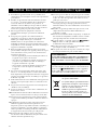
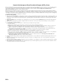
CAUTION: READ THIS BEFORE OPERATING YOUR UNIT.
En
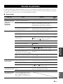
1 To assure the finest performance, please read this manual
carefully. Keep it in a safe place for future reference.
2 Install this sound system in a well ventilated, cool, dry, clean
place – away from direct sunlight, heat sources, vibration,
dust, moisture, and/or cold. Allow ventilation space of at least
30 cm on the top, 20 cm on the left and right, and 20 cm on
the back of this unit.
3 Locate this unit away from other electrical appliances, motors,
or transformers to avoid humming sounds.
4 Do not expose this unit to sudden temperature changes from
cold to hot, and do not locate this unit in a environment with
high humidity (i.e. a room with a humidifier) to prevent
condensation inside this unit, which may cause an electrical
shock, fire, damage to this unit, and/or personal injury.
5 Avoid installing this unit where foreign object may fall onto
this unit and/or this unit may be exposed to liquid dripping or
splashing. On the top of this unit, do not place:
– Other components, as they may cause damage and/or
discoloration on the surface of this unit.
– Burning objects (i.e. candles), as they may cause fire,
damage to this unit, and/or personal injury.
– Containers with liquid in them, as they may fall and liquid
may cause electrical shock to the user and/or damage to
this unit.
6 Do not cover this unit with a newspaper, tablecloth, curtain,
etc. in order not to obstruct heat radiation. If the temperature
inside this unit rises, it may cause fire, damage to this unit,
and/or personal injury.
7 Do not plug in this unit to a wall outlet until all connections
are complete.
8 Do not operate this unit upside-down. It may overheat,
possibly causing damage.
9 Do not use force on switches, knobs and/or cords.
10 When disconnecting the power cable from the wall outlet,
grasp the plug; do not pull the cord.
11 Do not clean this unit with chemical solvents; this might
damage the finish. Use a clean, dry cloth.
12 Only voltage specified on this unit must be used. Using this
unit with a higher voltage than specified is dangerous and may
cause fire, damage to this unit, and/or personal injury. Yamaha
will not be held responsible for any damage resulting from use
of this unit with a voltage other than specified.
13 To prevent damage by lightning, keep the power cord and
outdoor antennas disconnected from a wall outlet or the unit
during a lightning storm.
14 Do not attempt to modify or fix this unit. Contact qualified
Yamaha service personnel when any service is needed. The
cabinet should never be opened for any reasons.
15 When not planning to use this unit for long periods of time
(i.e. vacation), disconnect the AC power plug from the wall
outlet.
16 Install this unit near the AC outlet and where the AC power
plug can be reached easily.
17 Be sure to read the “Troubleshooting” section on common
operating errors before concluding that this unit is faulty.
18 Before moving this unit, press ASTANDBY/ON to set this
unit in the standby mode, and disconnect the AC power plug
from the wall outlet.
19 The batteries shall not be exposed to excessive heat such as
sunshine, fire or like.
20 Excessive sound pressure from earphones and headphones can
cause hearing loss.
■ For U.K. customers
If the socket outlets in the home are not suitable for the
plug supplied with this appliance, it should be cut off and
an appropriate 3 pin plug fitted. For details, refer to the
instructions described below.
The plug severed from the mains lead must be destroyed, as a
plug with bared flexible cord is hazardous if engaged in a live
socket outlet.
■ Special Instructions for U.K. Model
Caution: Read this before operating your unit.
WARNING
TO REDUCE THE RISK OF FIRE OR ELECTRIC
SHOCK, DO NOT EXPOSE THIS UNIT TO RAIN
OR MOISTURE.
This unit is not disconnected from the AC power
source as long as it is connected to the wall outlet, even
if this unit itself is turned off by
A
STANDBY/ON.
This state is called the standby mode. In this state, this
unit is designed to consume a very small quantity of
power.
Note
IMPORTANT
THE WIRES IN MAINS LEAD ARE COLOURED IN
ACCORDANCE WITH THE FOLLOWING CODE:
Blue: NEUTRAL
Brown: LIVE
As the colours of the wires in the mains lead of this apparatus
may not correspond with the coloured markings identifying
the terminals in your plug, proceed as follows:
The wire which is coloured BLUE must be connected to the
terminal which is marked with the letter N or coloured
BLACK. The wire which is coloured BROWN must be
connected to the terminal which is marked with the letter L or
coloured RED.
Making sure that neither core is connected to the earth
terminal of the three pin plug.
This symbol mark is according to the
EU directive 2002/96/EC.
This symbol mark means that electrical
and electronic equipment, at their end-
of-life, should be disposed of separately
from your household waste.
Please act according to your local rules
and do not dispose of your old products
with your normal household waste.

1 En
PREPARATIONINTRODUCTION
BASIC
OPERATION
ADVANCED
OPERATION
ADDITIONAL
INFORMATION
APPENDIX
English
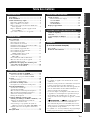
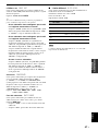
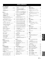
Features ................................................................... 2
Getting started ........................................................ 3
Quick start guide .................................................... 4
Preparation: Check the items ..................................... 4
Step 1: Set up your speakers...................................... 5
Step 2: Connect your DVD player and other
components............................................................ 6
Step 3: Turn on the power and press SCENE 1
button..................................................................... 7
What do you want to do with this unit?..................... 8
Connections............................................................. 9
Rear panel .................................................................. 9
Placing speakers....................................................... 10
Connecting speakers ................................................ 11
Information on jacks and cable plugs ...................... 13
Information on HDMI™.......................................... 14
Connecting video components................................. 15
Connecting audio components................................. 17
Connecting to the VIDEO AUX jacks on the front
panel .................................................................... 18
Connecting the FM and AM antennas ..................... 18
Connecting the power cable..................................... 19
Turning on and off the power .................................. 19
Front panel display .................................................. 20
Optimizing the speaker setting for your listening
room (YPAO) .................................................... 22
Using AUTO SETUP .............................................. 22
Selecting the SCENE templates........................... 25
Selecting the desired SCENE template.................... 25
Creating your original SCENE templates................ 28
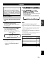
Playback ................................................................ 29
Basic operations....................................................... 29
Additional operations............................................... 30
Sound field programs ........................................... 34
Sound field program descriptions............................ 34
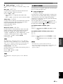
FM/AM tuning ...................................................... 37
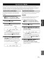
Automatic tuning ..................................................... 37
Manual tuning.......................................................... 37
Automatic preset tuning........................................... 38
Manual preset tuning ............................................... 38
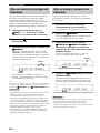
Selecting preset stations........................................... 39
Exchanging preset stations ...................................... 39
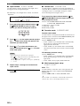
Radio Data System tuning
(Europe and Russia models only).................... 40
Displaying the Radio Data System information ...... 40
Selecting the Radio Data System program type
(PTY SEEK mode).............................................. 41
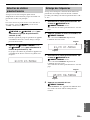
Using the enhanced other networks (EON) data
service.................................................................. 42
Recording .............................................................. 43
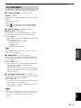
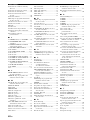
Set menu.................................................................44
Using set menu ........................................................ 45
1 SOUND MENU.................................................... 46
2 INPUT MENU...................................................... 49
3 OPTION MENU................................................... 51
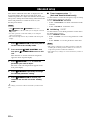
Advanced setup......................................................52
Troubleshooting.....................................................53
Glossary..................................................................58
Specifications .........................................................60
Index.......................................................................61
(at the end of this manual)
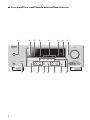
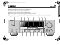
Front panel................................................................i
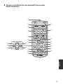
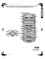
Remote control ....................................................... ii
Contents
INTRODUCTION
PREPARATION
BASIC OPERATION
ADVANCED OPERATION
ADDITIONAL INFORMATION
APPENDIX
About this manual
• y indicates a tip for your operation.
• Some operations can be performed by using either the
buttons on the front panel or the ones on the remote
control. In case the button names differ between the front
panel and the remote control, the button name on the
remote control is given in parentheses.
• This manual is printed prior to production. Design and
specifications are subject to change in part as a result of
improvements, etc. In case of differences between the
manual and product, the product has priority.
•“
A
STANDBY/ON” or “
4
DVD” (example) indicates
the name of the parts on the front panel or the remote
control. Refer to the attached sheet or the pages at the end
of this manual for the information about each position of
the parts.
•
The symbol “☞ ” with page number(s) indicates the
corresponding reference page(s).

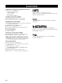
Features
2 En
Built-in 5-channel power amplifier
◆ Minimum RMS output power
(1 kHz, 0.9% THD, 6 Ω)
Front: 100 W/ch
Center: 100 W
Surround: 100 W/ch
SCENE select function
◆ Preset SCENE templates for various situations
◆ SCENE template customizing capability
Decoders and DSP circuits
◆ Proprietary Yamaha technology for the creation of
multi-channel surround sound
◆ Compressed Music Enhancer mode
◆ Dolby Digital decoder
◆ Dolby Pro Logic/Dolby Pro Logic II decoder
◆ DTS decoder
◆ Virtual CINEMA DSP
◆ SILENT CINEMA
™
Sophisticated FM/AM tuner
◆ 40-station random and direct preset tuning
◆ Automatic preset tuning
HDMI (High-Definition Multimedia Interface)
◆ HDMI interface for standard, enhanced or high-definition
video (includes 1080p video signal transmission)
Other features
◆ 192-kHz/24-bit D/A converter
◆ 6 additional input jacks for discrete multi-channel input
◆ Component video input/output capability
(3 COMPONENT VIDEO INs and 1 MONITOR OUT)
◆ Sleep timer
◆ Cinema and music night listening modes
◆ Remote control capability
Manufactured under license from Dolby Laboratories.
“Dolby”, “Pro Logic”, and the double-D symbol are trademarks
of Dolby Laboratories.
“SILENT CINEMA” is a trademark of Yamaha Corporation.
“HDMI”, the “HDMI” logo and “High-Definition Multimedia
Interface” are trademarks or registered trademarks of HDMI
Licensing LLC.
“DTS” and “DTS Digital Surround” are registered trademarks of
DTS, Inc.
Features

Getting started
3 En
INTRODUCTION
English
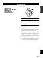
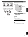
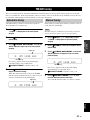
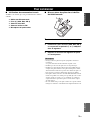
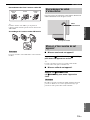
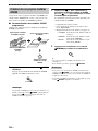
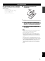
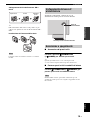
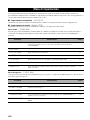
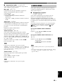
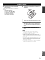
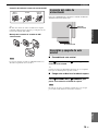
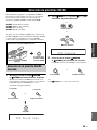
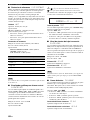
■ Checking the supplied accessories
Check that you received all of the following parts.
❏ Remote control
❏ Batteries (2) (AAA, R03, UM-4)
❏ AM loop antenna
❏ Indoor FM antenna
❏ Optimizer microphone
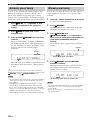
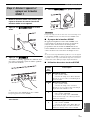
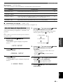
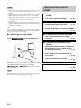
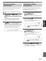
■ Installing batteries in the remote control
1 Take off the battery compartment cover.
2 Insert the two supplied batteries
(AAA, R03, UM-4) according to the polarity
markings (+ and –) on the inside of the
battery compartment.
3 Snap the battery compartment cover back
into place.
• Change all of the batteries if you notice the following condition:
– the operation range of the remote control decreases.
• Do not use an old battery and a new one together.
• Do not use different types of batteries (such as alkaline and
manganese batteries) together. Read the packaging carefully as
these different types of batteries may have the same shape and
color.
• If the batteries have leaked, dispose of them immediately. Avoid
touching the leaked material or letting it come into contact with
clothing, etc. Clean the battery compartment thoroughly before
installing new batteries.
• Do not throw away batteries with general house waste; dispose
of them correctly in accordance with your local regulations.
Getting started
Notes
1
3
2

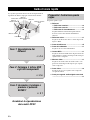
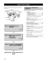
Quick start guide
4 En
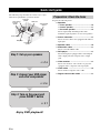
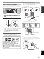
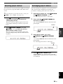
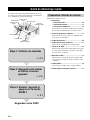
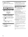
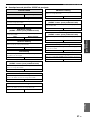
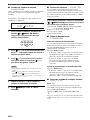
The following steps describe the easiest way to enjoy
DVD movie playback in your home theater.
Prepare the following items.
❏ Speakers
❏ Front speaker ..................................... x 2
❏ Center speaker ................................... x 1
❏ Surround speaker .............................. x 2
Select magnetically shielded speakers. The
minimum required speakers are two front speakers.
❏ Active subwoofer ................................... x 1
Select an active subwoofer equipped with an RCA
input jack.
❏ Speaker cable ......................................... x 5
❏ Subwoofer cable ..................................... x 1
Select a monaural RCA cable.
❏ DVD player .............................................. x 1
Select DVD player equipped with coaxial digital
audio output jack and composite video output
jack.
❏ Video monitor ......................................... x 1
Select a TV monitor, video monitor or projector
equipped with a composite video input jack.
❏ Video cable ............................................. x 2
Select an RCA composite video cable.
❏ Digital coaxial audio cable .................... x 1
Quick start guide
Front right
speaker
Subwoofer
Surround left
speaker
Front left
speaker
Surround right
speaker
Center speaker
Video monitor
DVD player
Enjoy DVD playback!
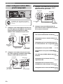
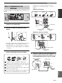
Step 1: Set up your speakers
☞
P. 5
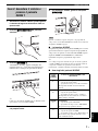
Step 2: Connect your DVD player
and other components
Step 3: Turn on the power and
press SCENE 1 button
☞
P. 6
☞
P. 7
Preparation: Check the items

Quick start guide
5 En
INTRODUCTION
English
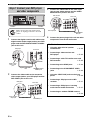
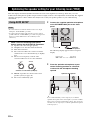
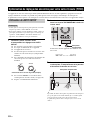
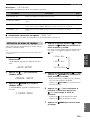
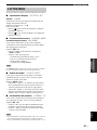
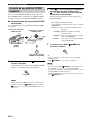
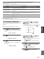
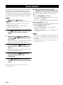
Place your speakers in the room and connect them to this
unit.
1 Place your speakers and subwoofer in the
room.
2 Connect speaker cables to each speaker.
Cables are colored or shaped differently, perhaps with
a stripe, groove or ridge. Connect the striped
(grooved, etc.) cable to the “+” (red) terminals of
your speaker. Connect the plain cable to the “–”
(black) terminals.
3 Connect each speaker cable to the
corresponding speaker terminal on this unit.
1 Make sure that this unit and the subwoofer are
unplugged from the AC wall outlets.
2 Twist the exposed wires of the speaker cables
together to prevent short circuits.
3 Do not let the bare speaker wires touch each other.
4 Do not let the bare speaker wires touch any metal
part of this unit.
Be sure to connect the left channel (L), right channel
(R), “+” (red) and “–” (black) properly.
Front speakers
Center and surround speakers
4 Connect the subwoofer cable to the input
jack on the subwoofer and the SUBWOOFER
OUTPUT jack on this unit.
Step 1: Set up your speakers
LRLR
LR
L
R
L
R
COMPONENT VIDEO
HDMI
VIDEO
AUDIOMULTI CH INPUT
DIGITAL INPUT
OUTPUT
ANTENNA
SPEAKERS
1
2
3
DVD DTV/CBL DVR
DVD
DVD
COAXIAL
OPTICAL
CD
DTV/CBL
DTV/
CBL
DVDOUT DTV/CBL
SURROUND CENTER FRONT B
FRONT A
MONITOR
OUT
MD/
CD-R
SUB
WOOFER
OUT
(REC)
IN
(PLAY)
DVR
DVD
FRONT CENTER
SUBWOOFER
SURROUND
DTV/CBL DVR CD
IN
OUT
IN
OUT
MONITOR
OUT
AM
GND
FM
75
UNBAL.
Y
P
R
P
B
12 3 4
To the front right
speaker
To the front left
speaker
Loosen Insert Tighten
To the surround
left speaker
To the center speaker
To the surround
right speaker
Press
down
Insert Release
SUBWOOFER
OUTPUT jack
Subwoofer cable
Input jack
AV receiver
Subwoofer

Quick start guide
6 En
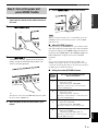
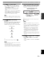
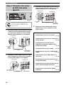
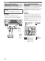
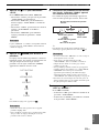
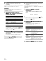
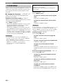
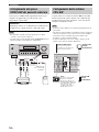
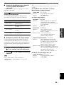
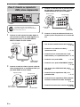
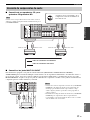
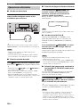
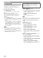
1 Connect the digital coaxial audio cable to the
digital coaxial audio output jack on your DVD
player and the DVD DIGITAL INPUT COAXIAL
jack on this unit.
2 Connect the video cable to the composite
video output jack on your DVD player and the
DVD VIDEO jack on this unit.
3 Connect the video cable to the video input
jack on your video monitor and the VIDEO
MONITOR OUT jack on this unit.
4 Connect the power plug of this unit and other
components into the AC wall outlet.
Step 2: Connect your DVD player
and other components
LRLR
LR
L
R
L
R
COMPONENT VIDEO
HDMI
VIDEO
AUDIOMULTI CH INPUT
DIGITAL INPUT
OUTPUT
ANTENNA
SPEAKERS
1
2
3
DVD DTV/CBL DVR
DVD
DVD
COAXIAL
OPTICAL
CD
DTV/CBL
DTV/
CBL
DVDOUT DTV/CBL
SURROUND CENTER FRONT B
FRONT A
MONITOR
OUT
MD/
CD-R
SUB
WOOFER
OUT
(REC)
IN
(PLAY)
DVR
DVD
FRONT CENTER
SUBWOOFER
SURROUND
DTV/CBL DVR CD
IN
OUT
IN
OUT
MONITOR
OUT
AM
GND
FM
75
UNBAL.
Y
P
R
P
B
Make sure that this unit and the DVD
player are unplugged from the AC wall
outlets.
Digital coaxial
audio output
jack
Digital coaxial audio
cable
DVD DIGITAL INPUT
COAXIAL jack
DVD player
AV receiver
Composite video
output jack
Video cable
DVD VIDEO jack
DVD player
AV receiver
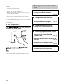
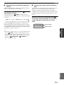
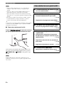
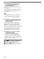
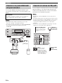
■ For further connections
• Using the other kind of speaker
combinations
☞
P. 10
• Connecting a video monitor and
DVD player
☞
P. 15
• Connecting a cable TV/satellite tuner and
DVD recorder
☞
P. 15
• Connecting to the HDMI jacks
☞
P. 16
• Connecting to the COMPONENT VIDEO
jacks
☞
P. 16
• Using the VIDEO AUX jacks on the front
panel
☞
P. 18
• Connecting a CD player and an MD
recorder
☞
P. 17
• Connecting a DVD player via analog
multi-channel audio connection
☞
P. 17
• Connecting an outdoor FM/AM antenna
☞
P. 18
Video monitor
AV receiver
Video input jack
Video cable
VIDEO MONITOR
OUT jack

Quick start guide
7 En
INTRODUCTION
English
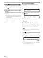
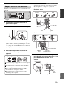
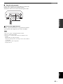
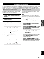
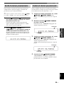
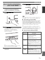
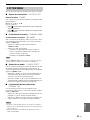
1 Turn on the video monitor and then set the
input source selector of the video monitor to
this unit.
2 Press
ASTANDBY/ON
on the front panel.
3 Press
P
SCENE 1.
“DVD Movie Viewing” appears in the front panel
display, and this unit automatically optimize own
status for the DVD playback.
y
The indicator on the selected SCENE button lights up while
this unit is in the SCENE mode.
4 Start playback of the desired DVD on your
player.
5 Rotate
H
VOLUME to adjust the volume.
When you change the input source or sound field program, the
SCENE mode is deactivated and the indicator on the SCENE
button turns off.
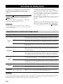
■ About SCENE function
Just by pressing one SCENE button, you can turn on this
unit and recall your favorite input source and sound field
program according to the SCENE template that has been
assigned to the SCENE button. The SCENE templates are
built combinations of input sources and sound field
programs.
y
If you connect a Yamaha product that has capability of the
SCENE control signals, this unit can automatically activate the
component and start playback. Refer to the instruction manual of
the DVD player for further information.
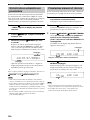
■ Using the other SCENE buttons
Step 3: Turn on the power and
press SCENE 1 button
Note
Default
SCENE
button
The name of the SCENE template
and its description
SCENE
1
DVD Movie Viewing
– input source: DVD
– sound field program: STRAIGHT
For when you want to enjoy a movie from the
connected DVD player.
SCENE
2
Music Disc Listening
– input source: DVD
– sound field program: 2ch Stereo
For when you want to listen to a music disc from
the connected DVD player.
SCENE
3
TV Viewing
*1
– input source: DTV/CBL
– sound field program: STRAIGHT
For when you want to watch a TV program.
SCENE
4
Radio Listening
*2, *3, *4
– input source: TUNER
– sound field program: Music Enh. 5ch
For when you want to listen to a music program
from the FM radio station

Quick start guide
8 En
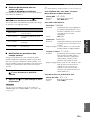
*1
You must connect a cable TV or a satellite tuner to this unit in
advance. See page 16 for details.
*2
You need to connect the supplied FM and AM antennas to this
unit in advance. See page 18 for details.
*3
You have to tune into the desired radio station. See page 37 to
39 for the tuning information.
*4
To achieve the best possible reception, orient the connected
AM loop antenna, or adjust the position of the end of the
indoor FM antenna.
y
If you cannot find the desired situation, you can select and change
the assigned SCENE template for the SCENE buttons. See
page 25 for details.
■ After using this unit...
Press
A
STANDBY/ON on the front panel to set
this unit to the standby mode.
This unit is set to the standby mode. To turn on this unit
from the standby mode, press
A
STANDBY/ON (or
A
POWER). See page 19 for details.
In the standby mode, this unit consumes a small amount of power
in order to receive infrared signals from the remote control.
Notes
Note
What do you want to do with this
unit?
■ Customizing the SCENE templates
• Using various SCENE templates
☞
P. 25
■ Using various input sources
• Basic controls of this unit
☞
P. 29
• Enjoying FM/AM radio programs
☞
P. 37
■ Using various sound features
• Using various sound field programs
☞
P. 34
■ Adjusting the parameters of this unit
• Automatically optimizing the speaker
parameters for your listening room
(AUTO SETUP)
☞
P. 22
• Manually adjusting various parameters of
this unit
☞
P. 44
• Adjusting the advanced parameters
☞
P. 52
■ Additional features
• Automatically turning off this unit
☞
P. 33

Connections
9 En
PREPARATION
English
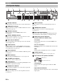
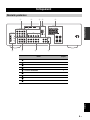
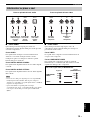
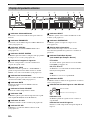
Connections
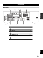
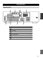
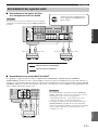
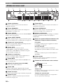
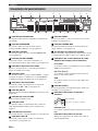
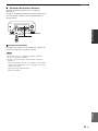
Rear panel
Name See page
1
COMPONENT VIDEO jacks 16
2
HDMI jacks 16
3
VIDEO jacks 15
4
ANTENNA terminals 18
5
SPEAKERS terminals 11
6
DIGITAL INPUT jacks 15, 17
7
MULTI CH INPUT jacks 17
8
AUDIO jacks 15, 17
9
SUBWOOFER OUTPUT jack 11
LRLR
LR
L
R
L
R
COMPONENT VIDEO
HDMI
VIDEO
AUDIOMULTI CH INPUT
DIGITAL INPUT
OUTPUT
ANTENNA
SPEAKERS
1
2
3
DVD DTV/CBL DVR
DVD
DVD
COAXIAL
OPTICAL
CD
DTV/CBL
DTV/
CBL
DVDOUT DTV/CBL
SURROUND CENTER FRONT B
FRONT A
MONITOR
OUT
MD/
CD-R
SUB
WOOFER
OUT
(REC)
IN
(PLAY)
DVR
DVD
FRONT CENTER
SUBWOOFER
SURROUND
DTV/CBL DVR CD
IN
OUT
IN
OUT
MONITOR
OUT
AM
GND
FM
75
UNBAL.
Y
P
R
P
B
1234 5
67 8 9

10 En
Connections
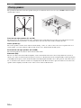
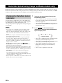
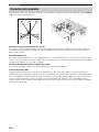
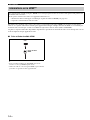
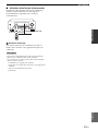
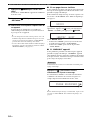
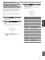
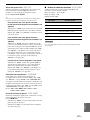
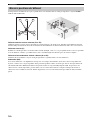
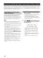
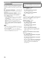
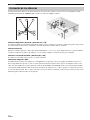
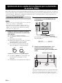
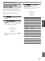
The speaker layout below shows the speaker setting we recommend. You can use it to enjoy CINEMA DSP and multi-
channel audio sources.
Front left and right speakers (FL and FR)
The front speakers are used for the main source sound plus effect sounds. Place these speakers at an equal distance from the
ideal listening position. The distance of each speaker from each side of the video monitor should be the same.
Center speaker (C)
The center speaker is for the center channel sounds (dialog, vocals, etc.). If for some reason it is not practical to use a
center speaker, you can do without it. Best results, however, are obtained with the full system.
Surround left and right speakers (SL and SR)
The surround speakers are used for effect and surround sounds.
Subwoofer (SW)
The use of a subwoofer with a built-in amplifier, such as the Yamaha Active Servo Processing Subwoofer System, is
effective not only for reinforcing bass frequencies from any or all channels, but also for high fidelity sound reproduction
of the LFE (low-frequency effect) channel included in Dolby Digital and DTS sources. The position of the subwoofer is
not so critical, because low bass sounds are not highly directional. But it is better to place the subwoofer near the front
speakers. Turn it slightly toward the center of the room to reduce wall reflections.
Placing speakers
60˚
30˚
FL
FR
C
SL
SR
SR
80˚
SL
FR
FL
C
SL
SR
SW

11 En
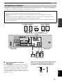
Connections
PREPARATION
English
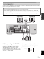
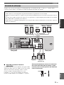
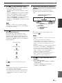
Be sure to connect the left channel (L), right channel (R), “+” (red) and “–” (black) properly. If the connections are faulty,
this unit cannot reproduce the input sources accurately.
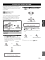
■ Before connecting to the SPEAKERS
terminal
A speaker cord is actually a pair of insulated cables
running side by side. Cables are colored or shaped
differently, perhaps with a stripe, groove or ridges.
Connect the striped (grooved, etc.) cable to the “+” (red)
terminals of this unit and your speaker. Connect the plain
cable to the “–” (black) terminals.
Remove approximately 10 mm (3/8”) of insulation
from the end of each speaker cable and then
twist the bare wires of the cable together to
prevent short circuits.
Connecting speakers
Caution
• Use speakers with the specified impedance shown on the rear panel of this unit.
• Before connecting the speakers, make sure that this the AC power plug is disconnected from the AC wall outlet.
• Do not let the bare speaker wires touch each other or let them touch any metal part of this unit. This could damage
this unit and/or speakers.
• Use magnetically shielded speakers. If this type of speakers still creates the interference with the monitor, place the
speakers away from the monitor.
LRLR
LR
L
R
L
R
COMPONENT VIDEO
HDMI
VIDEO
AUDIOMULTI CH INPUT
DIGITAL INPUT
OUTPUT
ANTENNA
SPEAKERS
1
2
3
DVD DTV/CBL DVR
DVD
DVD
COAXIAL
OPTICAL
CD
DTV/CBL
DTV/
CBL
DVDOUT DTV/CBL
SURROUND CENTER FRONT B
FRONT A
MONITOR
OUT
MD/
CD-R
SUB
WOOFER
OUT
(REC)
IN
(PLAY)
DVR
DVD
FRONT CENTER
SUBWOOFER
SURROUND
DTV/CBL DVR CD
IN
OUT
IN
OUT
MONITOR
OUT
AM
GND
FM
75
UNBAL.
Y
P
R
P
B
Subwoofer
Center
speaker
Front speakers (B)
LeftRight
Surround speakers
Front speakers (A)
LeftRight
LeftRight
10 mm (3/8”)

12 En
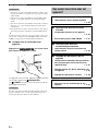
Connections
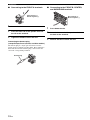
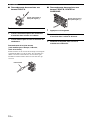
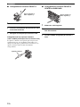
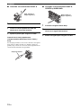
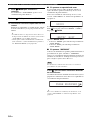
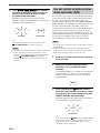
■ Connecting to the FRONT A terminals
1 Loosen the knob.
2 Insert the bare end of the speaker wire into
the slit on the terminal.
3 Tighten the knob to secure the wire.
Connecting the banana plug
(except Europe, Russia, Korea, and Asia models)
The banana plug is a single-pole electrical connector
widely used to terminate speaker cables. First, tighten the
knob and then insert the banana plug connector into the
end of the corresponding terminal.
■ Connecting to the FRONT B, CENTER,
and SURROUND terminals
1 Press down the tab.
2 Insert the bare end of the speaker wire into
the hole on the terminal.
3 Release the tab to secure the wire.
1
2
3
Red: positive (+)
Black: negative (–)
Banana plug
Red: positive (+)
Black: negative (–)

13 En
Connections
PREPARATION
English
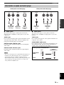
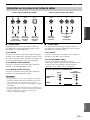
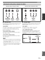
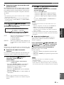
■ Audio jacks
This unit has three types of audio jacks. Connection
depends on the availability of audio jacks on your other
components.
AUDIO jacks
For conventional analog audio signals transmitted via left
and right analog audio cables. Connect red plugs to the
right jacks and white plugs to the left jacks.
DIGITAL AUDIO COAXIAL jacks
For digital audio signals transmitted via coaxial digital
audio cables.
DIGITAL AUDIO OPTICAL jacks
For digital audio signals transmitted via optical digital
audio cables.
• You can use the digital jacks to input PCM, Dolby Digital and
DTS bitstreams. All digital input jacks are compatible with
digital signals with up to 96 kHz of sampling frequency.
• This unit handles digital and analog signals independently. Thus
audio signals input at the digital jacks are not output at the
analog AUDIO OUT (REC) jacks.
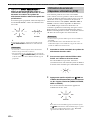
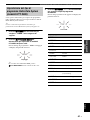
■ Video jacks
This unit has two types of video jacks. Connection
depends on the availability of input jacks on your video
monitor.
VIDEO jacks
For conventional composite video signals transmitted via
composite video cables.
COMPONENT VIDEO jacks
For component signals, separated into the luminance (Y)
and chrominance (P
B, PR) video signals transmitted on
separate wires of component video cables.
Information on jacks and cable plugs
VIDEO
COMPONENT VIDEO
Y P
B
P
R
PB
Y
P
R
V
COAXIAL
DIGITAL AUDIO
AUDIO
OPTICAL
DIGITAL AUDIO
R
L
C
O
R
L
Left and right
analog audio
cable plugs
Optical
digital
audio cable
plug
Coaxial
digital audio
cable plug
Composite
video cable
plug
Component
video cable
plugs
Audio jacks and cable plugs Video jacks and cable plugs
(Red)(White) (Orange) (Yellow) (Green) (Blue) (Red)
Notes
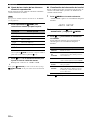
PR
P
B
Y
P
R
P
B
Y
Video signal flow for MONITOR OUT
Output
(MONITOR OUT)
Input
COMPONENT
VIDEO
VIDEO

14 En
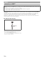
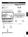
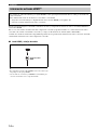
Connections
You can play back pictures by connecting your video monitor and video source component to this unit using HDMI
connections.
At that time, audio/video signals output from the connected component (such as DVD player etc.) are output to the
connected video monitor only when this unit is turned on and set to the input source (DVD or DTV/CBL).
Furthermore, available audio/video signals depend on the specification of the connected video monitor. Refer to the
instruction manual of each connected component.
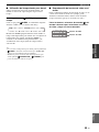
■ HDMI jack and cable plug
y
• We recommend using an HDMI cable shorter than 5 meters
(16 feet) with the HDMI logo printed on it.
• Use a conversion cable (HDMI jack
↔ DVI-D jack) to connect
this unit to other DVI components.
Information on HDMI™
Audio signals input at the HDMI jack are not output from any speaker terminals but output from the connected video
monitor.
To enjoy the sound from speakers connected to this unit,
–make an analog or digital connection besides the HDMI connection (see page 16).
–mute the volume of the connected video monitor.
HDMI cable
plug
HDMI

15 En
Connections
PREPARATION
English
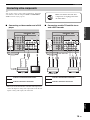
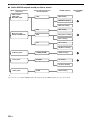
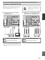
y
You can also connect a video monitor, DVD player, digital TV,
and cable TV to this unit using the HDMI or COMPONENT
VIDEO connection (see page 16).
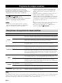
■ Connecting a video monitor and a DVD
player
*
When you use the internal tuner of the TV as the input source,
connect the digital or analog audio output jacks of the TV and
digital or analog audio input jacks of this unit.
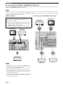
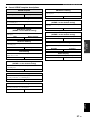
■ Connecting a cable TV/satellite tuner
and a DVD recorder
Connecting video components
Make sure that this unit and other
components are unplugged from the
AC wall outlets.
L
R
L
R
COMPONENT VIDEO
HDMI
VIDEO
AUDIOMULTI CH INPUT
DIGITAL INPUT
1
2
3
DVD DTV/CBL DVR
DVD
DVD
COAXIAL
OPTICAL
CD
DTV/CBL
DTV/
CBL
DVDOUT DTV/CBL
MONITOR
OUT
DVR
DVD
FRONT CENTER
SUBWOOFER
SURROUND
DTV/CBL DVR CD
IN
OUT
IN
OUT
MONITOR
OUT
Y
P
R
P
B
C
L
R
VV
DVD player
Video monitor*
Video in
Audio out
Audio out
Video out
indicates recommended connections
indicates alternative connections
L
R
L
R
COMPONENT VIDEO
HDMI
VIDEO
AUDIOMULTI CH INPUT
DIGITAL INPUT
1
2
3
DVD DTV/CBL DVR
DVD
DVD
COAXIAL
OPTICAL
CD
DTV/CBL
DTV/
CBL
DVDOUT DTV/CBL
MONITOR
OUT
DVR
DVD
FRONT CENTER
SUBWOOFER
SURROUND
DTV/CBL DVR CD
IN
OUT
IN
OUT
MONITOR
OUT
Y
P
R
P
B
L
R
L
R
L
R
VVV
O
Cable TV or
Satellite tuner
DVD recorder
Audio out
Video out
Audio out
Audio out
Video out
Audio in
Video in
indicates recommended connections
indicates alternative connections

16 En
Connections
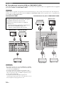
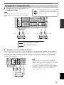
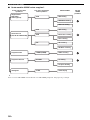
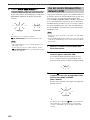
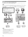
■ Connecting to the HDMI or COMPONENT VIDEO jacks
You can enjoy high-quality pictures by connecting your video monitor and video source components to this unit using
HDMI or COMPONENT VIDEO connections.
Be sure to connect your video components in the same way you connect your video monitor to this unit. For example, if you connect
your video monitor to this unit using an HDMI or COMPONENT VIDEO connection, connect your video components to this unit using
the HDMI or COMPONENT VIDEO connection.
HDMI connection
• Connect the input source components to the HDMI DVD or
HDMI DTV/CBL jack to display the video images on the video
monitor connected to the HDMI OUT jack.
• Audio/video signals output from the connected component
(such as DVD player etc.) are output to the connected video
monitor only when this unit is turned on and set to the input
source (DVD or DTV/CBL).
• Available audio/video signals depend on the specification of the
connected video monitor. Refer to the instruction manual of
each connected component.
Connecting to the COMPONENT VIDEO jacks
Note
Audio signals input at the HDMI jack are not output
from any speaker terminals but output from the
connected video monitor.
To enjoy the sound from speakers connected to this unit,
– make an analog or digital connection besides the
HDMI connection (see page 15).
– mute the volume of the connected video monitor.
Notes
O
MPONENT VIDEO
HDMI
VIDEO
AUDIOMULTI CH INPUT
ANTENNA
D
TV/CBL DVR
DVD DTV/CBL
DVDOUT DTV/CBL
MONITOR
OUT
DVR
IN
OUT
MONITOR
OUT
AM
GND
FM
75
UNBAL.
Video monitor
Cable TV or
satellite tuner
DVD player
L
R
L
R
COMPONENT VIDEO
H
D
VIDEO
AUDIOMULTI CH INPUT
DIGITAL INPUT
1
2
3
DVD DTV/CBL DVR
DVD
DVD
COAXIAL
OPTICAL
CD
DTV/CBL
DTV/
CBL
DVDOUT DTV/CBL
MO
N
O
DVR
DVD
FRONT CENTER
SUBWOOFER
SURROUND
DTV/CBL DVR
C
IN
OUT
IN
OUT
MONITOR
OUT
Y
P
R
P
B
P
R
P
B
Y
P
R
P
B
Y
P
R
P
B
Y
P
R
P
B
Y
DVD player
Video monitor
Cable TV or
satellite tuner
DVD recorder
Video in
Video out
Video out
Video out

17 En
Connections
PREPARATION
English
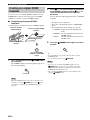
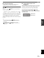
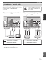
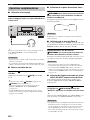
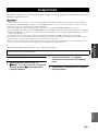
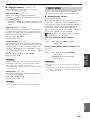
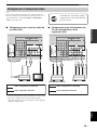
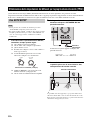
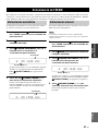
■ Connecting a CD player and a CD
recorder/MD recorder
When you connect your CD player via analog and digital
connection, priority is given to the signal input at the DIGITAL
INPUT jack.
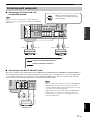
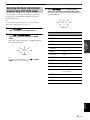
■ Connecting to the MULTI CH INPUT jacks
This unit is equipped with 6 additional input jacks (FRONT L/R, SURROUND L/R, CENTER and SUBWOOFER) for
discrete multi-channel input from a multi-format player, external decoder or sound processor. Connect the output jacks
on your multi-format player or external decoder to the MULTI CH INPUT jacks. Be sure to match the left and right
output jacks to the left and right input jacks for the front and surround channels.
• When you select the component connected to the MULTI CH
INPUT jacks as the input source (see page 30), this unit
automatically turns off the digital sound field processor, and
you cannot select sound field programs.
• This unit does not redirect signals input at the MULTI CH
INPUT jacks to accommodate for missing speakers. We
recommend that you connect a 5.1-channel speaker system
before using this feature.
Connecting audio components
Note
Make sure that this unit and other
components are unplugged from the
AC wall outlets.
L
R
L
R
VIDEO
AUDIOMULTI CH INPUT
DIGITAL INPUT
OUTPUT
1
2
3
DVD
DVD
COAXIAL
OPTICAL
CD
DTV/CBL
DTV/
CBL
MONITOR
OUT
MD/
CD-R
SUB
WOOFER
OUT
(REC)
IN
(PLAY)
DVR
DVD
FRONT CENTER
SUBWOOFER
SURROUND
DTV/CBL DVR CD
IN
OUT
IN
OUT
GND
FM
75
UNBAL.
Y
P
B
L
R
L
R
L
R
O
CD player CD recorder or MD
recorder
Audio outAudio out Audio inAudio out
indicates recommended connections
indicates alternative connections
L
R
L
R
MULTI CH INPUT
1
2
3
DVD
COAXIAL
CD
DTV/
CBL
DVD
FRONT CENTER
SUBWOOFER
SURROUND
DTV/CBL DVR
IN
L
R
L
R
Multi-format player or
external decoder
Center out
Subwoofer out
Surround out
Front out
Notes

18 En
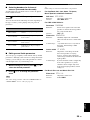
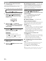
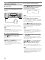
Connections
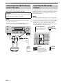
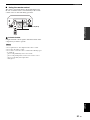
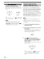
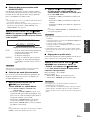
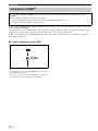
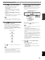
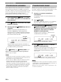
Use the VIDEO AUX jacks on the front panel to connect a
game console or a video camera to this unit.
• To reproduce the source signals input at these jacks, select
“V-AUX” as the input source.
• The audio signals input at the PORTABLE mini jack take
priority over the ones input at the AUDIO L/R jacks.
Both FM and AM indoor antennas are supplied with this
unit. In general, these antennas should provide sufficient
signal strength. Connect each antenna correctly to the
designated terminals.
• The AM loop antenna should be placed away from this unit.
• A properly installed outdoor antenna provides clearer reception
than an indoor one. If you experience poor reception quality,
install an outdoor antenna. Consult the nearest authorized
Yamaha dealer or service center about outdoor antennas.
• The AM loop antenna should always be connected, even if an
outdoor AM antenna is connected to this unit.
Connecting to the VIDEO AUX jacks
on the front panel
Caution
Be sure to turn down the volume of this unit and other
components before making connections.
Notes
STANDBY
/ON
PHONES
SPEAKERS
A/B/OFF
SILENT CINEMA
EDIT
PRESET/TUNING
BAND A/B/C/D/E
TONE CONTROL
PROGRAM
STRAIGHT NIGHT
EFFECT
SCENE
PRESET/TUNING MEMORY
OPTIMIZER MIC
TUNING AUTO/MAN'L
AUDIO SELEC T
INPUT
1234
VOLUME
R
L
AUDIO PORTABLE
VIDEO AUX
VIDEO
VIDEO L AUDIO R PORTABLE
VIDEO AUX
V
L
R
Game console or
video camera
3.5 mm
stereo mini
plug
Audio out
Video out
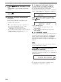
Connecting the FM and AM
antennas
Notes
E
O
ANTENNA
L
R
SURROUND
AUDIO OUTPUT
DVR
CD
DVR
AM
GND
FM
UNBAL.
75
OUT
MONITOR
OUT
MD/
O
UT
IN
AM loop
antenna
(supplied)
Ground
For maximum safety and
minimum interference,
connect the antenna GND
terminal to a good earth
ground. A good earth ground
is a metal stake driven into
moist earth.
Indoor FM
antenna
(supplied)
Outdoor AM antenna
Use a 5 to 10 m (16 to 32 ft) of
vinyl-covered wire extended
outdoors from a window.
Pagina se încarcă...
Pagina se încarcă...
Pagina se încarcă...
Pagina se încarcă...
Pagina se încarcă...
Pagina se încarcă...
Pagina se încarcă...
Pagina se încarcă...
Pagina se încarcă...
Pagina se încarcă...
Pagina se încarcă...
Pagina se încarcă...
Pagina se încarcă...
Pagina se încarcă...
Pagina se încarcă...
Pagina se încarcă...
Pagina se încarcă...
Pagina se încarcă...
Pagina se încarcă...
Pagina se încarcă...
Pagina se încarcă...
Pagina se încarcă...
Pagina se încarcă...
Pagina se încarcă...
Pagina se încarcă...
Pagina se încarcă...
Pagina se încarcă...
Pagina se încarcă...
Pagina se încarcă...
Pagina se încarcă...
Pagina se încarcă...
Pagina se încarcă...
Pagina se încarcă...
Pagina se încarcă...
Pagina se încarcă...
Pagina se încarcă...
Pagina se încarcă...
Pagina se încarcă...
Pagina se încarcă...
Pagina se încarcă...
Pagina se încarcă...
Pagina se încarcă...
Pagina se încarcă...
Pagina se încarcă...
Pagina se încarcă...
Pagina se încarcă...
Pagina se încarcă...
Pagina se încarcă...
Pagina se încarcă...
Pagina se încarcă...
Pagina se încarcă...
Pagina se încarcă...
Pagina se încarcă...
Pagina se încarcă...
Pagina se încarcă...
Pagina se încarcă...
Pagina se încarcă...
Pagina se încarcă...
Pagina se încarcă...
Pagina se încarcă...
Pagina se încarcă...
Pagina se încarcă...
Pagina se încarcă...
Pagina se încarcă...
Pagina se încarcă...
Pagina se încarcă...
Pagina se încarcă...
Pagina se încarcă...
Pagina se încarcă...
Pagina se încarcă...
Pagina se încarcă...
Pagina se încarcă...
Pagina se încarcă...
Pagina se încarcă...
Pagina se încarcă...
Pagina se încarcă...
Pagina se încarcă...
Pagina se încarcă...
Pagina se încarcă...
Pagina se încarcă...
Pagina se încarcă...
Pagina se încarcă...
Pagina se încarcă...
Pagina se încarcă...
Pagina se încarcă...
Pagina se încarcă...
Pagina se încarcă...
Pagina se încarcă...
Pagina se încarcă...
Pagina se încarcă...
Pagina se încarcă...
Pagina se încarcă...
Pagina se încarcă...
Pagina se încarcă...
Pagina se încarcă...
Pagina se încarcă...
Pagina se încarcă...
Pagina se încarcă...
Pagina se încarcă...
Pagina se încarcă...
Pagina se încarcă...
Pagina se încarcă...
Pagina se încarcă...
Pagina se încarcă...
Pagina se încarcă...
Pagina se încarcă...
Pagina se încarcă...
Pagina se încarcă...
Pagina se încarcă...
Pagina se încarcă...
Pagina se încarcă...
Pagina se încarcă...
Pagina se încarcă...
Pagina se încarcă...
Pagina se încarcă...
Pagina se încarcă...
Pagina se încarcă...
Pagina se încarcă...
Pagina se încarcă...
Pagina se încarcă...
Pagina se încarcă...
Pagina se încarcă...
Pagina se încarcă...
Pagina se încarcă...
Pagina se încarcă...
Pagina se încarcă...
Pagina se încarcă...
Pagina se încarcă...
Pagina se încarcă...
Pagina se încarcă...
Pagina se încarcă...
Pagina se încarcă...
Pagina se încarcă...
Pagina se încarcă...
Pagina se încarcă...
Pagina se încarcă...
Pagina se încarcă...
Pagina se încarcă...
Pagina se încarcă...
Pagina se încarcă...
Pagina se încarcă...
Pagina se încarcă...
Pagina se încarcă...
Pagina se încarcă...
Pagina se încarcă...
Pagina se încarcă...
Pagina se încarcă...
Pagina se încarcă...
Pagina se încarcă...
Pagina se încarcă...
Pagina se încarcă...
Pagina se încarcă...
Pagina se încarcă...
Pagina se încarcă...
Pagina se încarcă...
Pagina se încarcă...
Pagina se încarcă...
Pagina se încarcă...
Pagina se încarcă...
Pagina se încarcă...
Pagina se încarcă...
Pagina se încarcă...
Pagina se încarcă...
Pagina se încarcă...
Pagina se încarcă...
Pagina se încarcă...
Pagina se încarcă...
Pagina se încarcă...
Pagina se încarcă...
Pagina se încarcă...
Pagina se încarcă...
Pagina se încarcă...
Pagina se încarcă...
Pagina se încarcă...
Pagina se încarcă...
Pagina se încarcă...
Pagina se încarcă...
Pagina se încarcă...
Pagina se încarcă...
Pagina se încarcă...
Pagina se încarcă...
Pagina se încarcă...
Pagina se încarcă...
Pagina se încarcă...
Pagina se încarcă...
Pagina se încarcă...
Pagina se încarcă...
Pagina se încarcă...
Pagina se încarcă...
Pagina se încarcă...
Pagina se încarcă...
Pagina se încarcă...
Pagina se încarcă...
Pagina se încarcă...
Pagina se încarcă...
Pagina se încarcă...
Pagina se încarcă...
Pagina se încarcă...
Pagina se încarcă...
Pagina se încarcă...
Pagina se încarcă...
Pagina se încarcă...
Pagina se încarcă...
Pagina se încarcă...
Pagina se încarcă...
Pagina se încarcă...
Pagina se încarcă...
Pagina se încarcă...
Pagina se încarcă...
Pagina se încarcă...
Pagina se încarcă...
Pagina se încarcă...
Pagina se încarcă...
Pagina se încarcă...
Pagina se încarcă...
Pagina se încarcă...
Pagina se încarcă...
Pagina se încarcă...
Pagina se încarcă...
Pagina se încarcă...
Pagina se încarcă...
Pagina se încarcă...
Pagina se încarcă...
Pagina se încarcă...
Pagina se încarcă...
Pagina se încarcă...
Pagina se încarcă...
Pagina se încarcă...
Pagina se încarcă...
Pagina se încarcă...
Pagina se încarcă...
Pagina se încarcă...
Pagina se încarcă...
Pagina se încarcă...
Pagina se încarcă...
Pagina se încarcă...
Pagina se încarcă...
Pagina se încarcă...
Pagina se încarcă...
Pagina se încarcă...
Pagina se încarcă...
Pagina se încarcă...
Pagina se încarcă...
Pagina se încarcă...
Pagina se încarcă...
-
 1
1
-
 2
2
-
 3
3
-
 4
4
-
 5
5
-
 6
6
-
 7
7
-
 8
8
-
 9
9
-
 10
10
-
 11
11
-
 12
12
-
 13
13
-
 14
14
-
 15
15
-
 16
16
-
 17
17
-
 18
18
-
 19
19
-
 20
20
-
 21
21
-
 22
22
-
 23
23
-
 24
24
-
 25
25
-
 26
26
-
 27
27
-
 28
28
-
 29
29
-
 30
30
-
 31
31
-
 32
32
-
 33
33
-
 34
34
-
 35
35
-
 36
36
-
 37
37
-
 38
38
-
 39
39
-
 40
40
-
 41
41
-
 42
42
-
 43
43
-
 44
44
-
 45
45
-
 46
46
-
 47
47
-
 48
48
-
 49
49
-
 50
50
-
 51
51
-
 52
52
-
 53
53
-
 54
54
-
 55
55
-
 56
56
-
 57
57
-
 58
58
-
 59
59
-
 60
60
-
 61
61
-
 62
62
-
 63
63
-
 64
64
-
 65
65
-
 66
66
-
 67
67
-
 68
68
-
 69
69
-
 70
70
-
 71
71
-
 72
72
-
 73
73
-
 74
74
-
 75
75
-
 76
76
-
 77
77
-
 78
78
-
 79
79
-
 80
80
-
 81
81
-
 82
82
-
 83
83
-
 84
84
-
 85
85
-
 86
86
-
 87
87
-
 88
88
-
 89
89
-
 90
90
-
 91
91
-
 92
92
-
 93
93
-
 94
94
-
 95
95
-
 96
96
-
 97
97
-
 98
98
-
 99
99
-
 100
100
-
 101
101
-
 102
102
-
 103
103
-
 104
104
-
 105
105
-
 106
106
-
 107
107
-
 108
108
-
 109
109
-
 110
110
-
 111
111
-
 112
112
-
 113
113
-
 114
114
-
 115
115
-
 116
116
-
 117
117
-
 118
118
-
 119
119
-
 120
120
-
 121
121
-
 122
122
-
 123
123
-
 124
124
-
 125
125
-
 126
126
-
 127
127
-
 128
128
-
 129
129
-
 130
130
-
 131
131
-
 132
132
-
 133
133
-
 134
134
-
 135
135
-
 136
136
-
 137
137
-
 138
138
-
 139
139
-
 140
140
-
 141
141
-
 142
142
-
 143
143
-
 144
144
-
 145
145
-
 146
146
-
 147
147
-
 148
148
-
 149
149
-
 150
150
-
 151
151
-
 152
152
-
 153
153
-
 154
154
-
 155
155
-
 156
156
-
 157
157
-
 158
158
-
 159
159
-
 160
160
-
 161
161
-
 162
162
-
 163
163
-
 164
164
-
 165
165
-
 166
166
-
 167
167
-
 168
168
-
 169
169
-
 170
170
-
 171
171
-
 172
172
-
 173
173
-
 174
174
-
 175
175
-
 176
176
-
 177
177
-
 178
178
-
 179
179
-
 180
180
-
 181
181
-
 182
182
-
 183
183
-
 184
184
-
 185
185
-
 186
186
-
 187
187
-
 188
188
-
 189
189
-
 190
190
-
 191
191
-
 192
192
-
 193
193
-
 194
194
-
 195
195
-
 196
196
-
 197
197
-
 198
198
-
 199
199
-
 200
200
-
 201
201
-
 202
202
-
 203
203
-
 204
204
-
 205
205
-
 206
206
-
 207
207
-
 208
208
-
 209
209
-
 210
210
-
 211
211
-
 212
212
-
 213
213
-
 214
214
-
 215
215
-
 216
216
-
 217
217
-
 218
218
-
 219
219
-
 220
220
-
 221
221
-
 222
222
-
 223
223
-
 224
224
-
 225
225
-
 226
226
-
 227
227
-
 228
228
-
 229
229
-
 230
230
-
 231
231
-
 232
232
-
 233
233
-
 234
234
-
 235
235
-
 236
236
-
 237
237
-
 238
238
-
 239
239
-
 240
240
-
 241
241
-
 242
242
-
 243
243
-
 244
244
-
 245
245
-
 246
246
-
 247
247
-
 248
248
-
 249
249
-
 250
250
-
 251
251
-
 252
252
-
 253
253
-
 254
254
-
 255
255
-
 256
256
-
 257
257
-
 258
258
-
 259
259
-
 260
260
-
 261
261
-
 262
262
-
 263
263
-
 264
264
-
 265
265


Yamaha RX-V363 Manualul proprietarului
- Categorie
- Aparate de radio
- Tip
- Manualul proprietarului
în alte limbi
- français: Yamaha RX-V363 Le manuel du propriétaire
- English: Yamaha RX-V363 Owner's manual
- suomi: Yamaha RX-V363 Omistajan opas
- italiano: Yamaha RX-V363 Manuale del proprietario
- español: Yamaha RX-V363 El manual del propietario