Yamaha GC2020C Manualul proprietarului
- Categorie
- Compresoare de aer
- Tip
- Manualul proprietarului

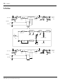
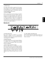
COMPRESSOR/LIMITER
GC2020C
Owner’s Manual
Mode d’emploi
Bedienungsanleitung
Manual del propietario
GC2020C
COMP/LIMITER
COMP
GAIN
REDUCTION
0
–4
–8
–16
–24
EXP GATE THRESHOLD RATIO ATTACK RELEASE INPUT OUTPUT
CHANNEL A CHANNEL B
SIGNAL PEAK
GAIN
REDUCTION
0
–4
–8
–16
–24
EXP GATE THRESHOLD RATIO ATTACK RELEASE INPUT OUTPUT
SIGNAL PEAK
LINK COMP
ON OFF
POWER
0 10 0 10 0 10 0 10
1
2
48
20
00
0.2
1
35
10
20
0.05
0.1
0.3 0.5
1
2
0 10 0 10 0 10 0 10
1
2
48
20
00
0.2
1
35
10
20
0.05
0.1
0.3 0.5
1
2
secms
secms

i
GC2020C Compressor/Limiter Owner’s Manual
English
IMPORTANT NOTICE FOR
THE UNITED KINGDOM
Connecting the Plug and Cord
IMPORTANT: The wires in this mains lead are coloured in accordance
with the following code:
BLUE : NEUTRAL
BROWN : LIVE
As the colours of the wires in the mains lead of this apparatus may not
correspond with the coloured markings identifying the terminals in your
plug proceed as follows:
The wire which is coloured BLUE must be connected to the terminal
which is marked with the letter N or coloured BLACK.
The wire which is coloured BROWN must be connected to the terminal
which is marked with the letter L or coloured RED.
Making sure that neither core is connected to the earth terminal of the
three pin plug.
* This applies only to products distributed by YAMAHA - KEMBLE
MUSIC (U.K.) LTD.
Welcome to the GC2020C Compressor/Limiter
Introduction
Thank you for choosing the Yamaha GC2020C Compres-
sor/Limiter. The GC2020C is a 2-channel high-performance
compressor/limiter designed for professional recording and
sound reinforcement applications. The GC2020C provides a
wide variety of control features for precise tailoring of com-
pression and limiting parameters. It also features an
expander gate to eliminate source noise that can be accentu-
ated by the compression process.
GC2020C compression can be used to add extra punch and
a more consistent level to a final mix, and channels can be
linked for stereo operation. A small amount of compression
provides a more consistent signal level when recording a
singer that tends to move closer to or further away from a
vocal microphone. Essentially, the compressor is reducing
the dynamic range. This technique can also be used with
other instruments, such as acoustic guitar, bass guitar, and
piano. In fact, any instrument with a wide dynamic range can
be recorded more easily with a little compression applied.
Creative compressor application include adding extra punch
to bass, snare, and tom tom drums. GC2020C limiting can
be used to protect speakers in a sound reinforcement system.
Whether your applications are signal control, signal correc-
tion, or simply creative—the GC2020C is flexible enough to
handle all your needs.
To get the best from your GC2020C, read this manual thor-
oughly, and keep it in a safe place for future reference.
Table of Contents
What’s a Compressor/Limiter? . . . . . . . . 1
Compressor/Limiter Functions . . . . . . 1
Compressor/Limiter Parameters . . . . . 2
Setting Up the Compressor/Limiter . . . 4
What’s an Expander/Gate? . . . . . . . . . . . 5
Setting Up the Expander/Gate . . . . . . 5
Controls & Connections . . . . . . . . . . . . . 6
Front Panel . . . . . . . . . . . . . . . . . . . . . 6
Rear Panel . . . . . . . . . . . . . . . . . . . . . . 7
Specifications . . . . . . . . . . . . . . . . . . . 8
Dimensions . . . . . . . . . . . . . . . . . . . . . 9
Block Diagram . . . . . . . . . . . . . . . . . 10

ii
GC2020C Compressor/Limiter Owner’s Manual
Precautions
Avoid excessive heat, humidity, dust,
and vibration
Keep the unit away from locations where it is likely to be
exposed to high temperatures or humidity—such as near
radiators, stoves, in direct sunlight, etc. Avoid locations that
are subject to excessive dust accumulation. Extreme vibra-
tions can cause mechanical damage.
Avoid physical shocks
Strong physical shocks can damage the unit. Handle it with
care.
Install the unit with plenty of space for ventilation
This unit should be installed in such a way as to maintain a
gap of 10 cm or more between the rear of the unit and the
wall. This will prevent heat build-up inside the unit and pos-
sible fire hazard.
Do not open the unit, or attempt
repairs or modifications yourself
This product contains no user-serviceable parts. Prefer all
maintenance to qualified Yamaha service personnel. Open-
ing the unit and/or tampering with the internal circuitry will
void the warranty.
Make sure the power is off before
making or removing connections
Always turn the power OFF prior to connecting or discon-
necting cables. This is important to prevent damage to the
unit itself as well as other connected equipment.
Handle cables carefully
Always plug and unplug cables—including the AC cord—by
gripping the connector, not the cord.
Clean with a soft dry cloth
Never use solvents such as benzine or thinner to clean the
unit. Wipe it clean with a soft, dry cloth.
Always use the correct power source
Make sure the power source voltage specified on the rear
panel matches your local AC mains supply:
US & Canadian Model: 120V AC, 60 Hz
General Model: 230V AC, 50 Hz
UK Model: 240V AC, 50 Hz

What’s a Compressor/Limiter?
1
GC2020C Compressor/Limiter Owner’s Manual
English
What’s a Compressor/Limiter?
This section explains the main functions of the Compressor/Limiter. Its parameters, setup procedure, and the expander/gate.
Compressor/Limiter Functions
Compressor
Generally, a compressor is used to fit a large signal into a
small space. Specifically, in a situation where the dynamic
range of the original audio signal is larger than the electronic
reproduction equipment that is to process it can handle, a
compressor can reduce the dynamic range of the signal to fit
neatly within the limits of the recording or reproduction
equipment. Of course, this must be done without adding
distortion to the signal itself.
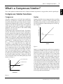
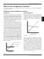
Compression is expressed in terms of a ratio—the compres-
sion ratio. This ratio describes how much the signal appear-
ing at the output of the compressor changes in relation to a
given change in the level of the original signal applied to the
input. If no compression is applied and the input signal
doubles in level, then the output signal will also double in
level, precisely following the change in the input signal. This
corresponds to a compression ratio of 1:1 (read “one to
one”) —a change of 1 at the input produces a change of 1 at
the output—i.e. no compression. Now if we apply some
compression, a smaller change in the level of the output sig-
nal will be observed for the same change in input signal
level. A compression ratio of 2:1, for example, would mean
that the level of the output signal will change only half as
much as the input signal. Expressed in decibels, a compres-
sion ratio of 20:1 would mean that a 20 dB change in the
level of the input signal would result in only a 1 dB change in
the level of the output signal. Thus, a compressor is able to
reduce the dynamic range of an audio signal by any desired
amount. See Figure 1.
Figure 1
Limiter
Limiting is basically extreme compression that is set to affect
only signals above a certain level. This is particularly useful
for limiting only peaks that exceed the handling capacity of
the related equipment, without affecting the rest of the sig-
nal. See Figure 2.
Figure 2
Suppose we wanted to limit the peak levels in a program to
a maximum of 0 dBm, in order to prevent saturation and
distortion in a tape recorder. First we would set the “thresh-
old” level to 0 dB—the threshold level is the input signal
level at which the limiter will begin to operate. Then we
would set the maximum (or near maximum) compression
available—
∞
:1 (infinity compression). Infinity compres-
sion means that absolutely no change in the output level will
occur no matter how much the input signal changes. As a
result, all signal content below the threshold level (0 dB) will
be passed exactly as it appears at the limiters input. Signals
exceeding the threshold level, however, will be output at the
threshold level and will rise no higher. In this case no signal
exceeding 0 dB will appear at the limiter’s output. The actual
audio signal remains untouched, just its average (r.m.s.)
level is kept within the defined limits.
1:1 NO COMPRESSION
2:1 COMPRESSION
Threshold
Level
Output Signal Level
Input Signal Level
COMPRESSION
(dB)
(dB)
0
Limiting
Threshold
Output Signal Level
Input Signal Level
LIMITING
0
(dB)
(dB)

2
Compressor/Limiter Parameters
GC2020C Compressor/Limiter Owner’s Manual
Compressor/Limiter Parameters
Threshold Level
Threshold is the signal level at which compression or limit-
ing begins. All signals below the set threshold level are
passed as received at the INPUT jacks, with no compression
or limiting applied. Signals going above the set threshold
level, however, are compressed or limited according to the
settings of the RATIO, ATTACK, and RELEASE controls.
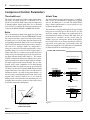
Ratio
This is the amount of compression applied to signals that
exceed the threshold level set by the THRESHOLD control.
The compression ratio is expressed in terms of the amount
of change in the level of the input signal in relation to the
corresponding amount of change in the level of the output
signal. A high ratio means a lot of compression. A compres-
sion ratio of 1:1, therefore, implies no compression—a
change of 1 in the level of the input signal produces a corre-
sponding change of 1 in the level of the output signal. A
compression ratio of 2:1, however, means that for a given
change in the level of the input signal (2) the level of the out-
put signal will only change half as much (1). The extreme
would be a compression ratio of
∞
:1 (infinity to one), mean-
ing that no matter how much the input signal level changes
the output signal level will remain constant. The
∞
:1 com-
pression ratio is most commonly used in hard limiting
applications where the signal level must be prevented from
exceeding a specific value (frequently 0 dB). Extremely high
compression ratios in the range of 20:1 can add sustain to
instrument sounds—especially electric guitar and bass—as
well as creating a contemporary drum sound. Lower com-
pression ratios—from less than 2:1 to 8:1—are useful for
making vocals sound smoother and minimizing the level
variations that occur when a speaker or singer moves closer
to or further away from a microphone.
Figure 3
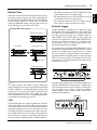
Attack Time
The Attack Time determines how long it takes—in millisec-
onds—before the full amount of compression is applied
once the threshold level is exceeded. The ATTACK time
range is from 0.2 milliseconds, a very fast attack, to a rela-
tively slow 20 milliseconds.
The attack time setting depends largely on the type of signal
being processed and the type of effect desired. A very fast
attack, for example, will compress the initial attack of an
instrumental note making it sound “dull”. High levels of
compression are sometimes used on electric guitar, for
example, to give the sound greater sustain. In this applica-
tion it is often better to set a longer attack time so that the
crisp attack of the guitar note “gets through” before full
compression is applied. Set the attack time to accommodate
the natural attack of the sound being processed.
Figure 4
+30
+20
+10
0
–10
–20
–30
–40
–50
Threshold level
Output Signal Level (dB)
Intput Signal Level (dB)
COMPRESSION RATIOS
–60–70 +30–50 –40 –30 –20 –10 0 +10 +20
1:1
2:1
4:1
8:1
20:1
:1
Attack Time set to zero
Input Signal
Fast Attack Time
Attack Time
Slow Attack Time
Attack Time
ATTACK TIME Control Function

Compressor/Limiter Parameters
3
GC2020C Compressor/Limiter Owner’s Manual
English
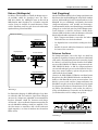
Release Time
The Release Time determines how long it takes for the com-
pression to return to zero once the audio signal falls below
the threshold level. The RELEASE time range is from 50 mil-
liseconds (0.05 seconds) to 2 seconds. Like the ATTACK
control, the RELEASE control setting depends on the type
of signal being processed and the desired effect.
Figure 5
The main reason for this control is that if compression
stopped abruptly the instant the signal fell below threshold
level there would be a corresponding abrupt and unnatural
change in the level of the audio signal—particularly with
musical instruments that have a long, gentle decay slope.
Unless a particular effect is desired, set the RELEASE time to
accommodate the signal being processed.
Link
This function makes the compressor/limiter of channel A
and of channel B operate together. When a compressor/lim-
iter is used to process a stereo signal, using two independent
channels of compression causes the stereo image to waver
unsteadily, producing an unnatural effect. If the two chan-
nels are linked, however, the same compression is applied to
both channels, preserving the stereo image. When Link is
ON, the parameters of both channels are linked as follows.
• The compressor/limiters use the Threshold Level setting
of the channel whose level setting is higher.
• The expander/noise gates use the Threshold Level setting
of the channel whose level setting is lower.
• For Attack Time and Release Time, the channel with the
faster (shorter) settings determines the settings.
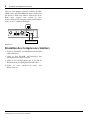
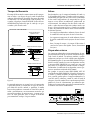
External trigger
Compressor/limiters normally begin compression when
they detect that the input signal has exceeded the threshold
level. However, it is also possible to use a signal other than
the input signal as the trigger. The GC2020C provides a
SIDE CHAIN OUT jack that splits the input signal and
sends it to an external device, and a SIDE CHAIN IN jack
that lets a signal from an external device control the com-
pressor/limiter. Using an external trigger allows more
sophisticated control of the GC2020C.
For example, if you connect the SIDE CHAIN OUT jack of
channel B to the SIDE CHAIN IN jack of channel A so that
channel A is controlled by an external trigger (i.e. channel
B), you can apply the compressor/limiter to the channel A
signal only when the channel B signal exceeds the threshold.
This is an easy way to produce the “ducking” effect that DJ's
or announcers use to automatically lower the volume of the
music when they speak.
By connecting an equalizer between the SIDE CHAIN OUT
and SIDE CHAIN IN jacks, boosting the 3–5 kHz region,
and setting that channel to operate with an external trigger,
you can apply a de-esser effect, in which the compres-
sor/limiter applies only to sibilant sounds (sounds with a
pronounced
S
component).
Release Time set to zero
Fast Release Time
Slow Release Time
Release Time
Input Signal
Release Time
RELEASE TIME Contorl Function
CHANNEL A
OUT
IN
INT EXT
KEY
OUT
IN
INT EXT
KEY
INPUT
+4dB
OUTPUT
+4dB
SIDECHAIN SIDECHAIN
INT EXT
CHANNEL A
OUT
IN
INT EXT
KEY
INPUT
+4dB
OUTPUT
+4dB
SIDECHAIN
INT EXT
Equalizer

4
Setting Up the Compressor/Limiter
GC2020C Compressor/Limiter Owner’s Manual
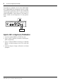
Setting Up the Compressor/Limiter
1. Set the INPUT and OUTPUT controls midway.
2. Set the Threshold Level and Ratio as appropriate for
your application.
3. Adjust the OUTPUT control so that the PEAK indicator
just lights up at the loudest signals.
4. Set the Attack and Release times as appropriate.

What’s an Expander/Gate?
5
GC2020C Compressor/Limiter Owner’s Manual
English
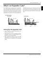
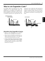
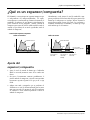
What’s an Expander/Gate?
The GC2020C features a expander/gate that is independent
of the compressor/limiter. Expander/gate is a function that
effectively eliminates hum or noise that would otherwise be
heard during silent portions of the program. It works by
closing the gate to cut off the output signal when the input
signal falls below a specified level (the gate threshold level).
Normally you will set the gate level below the lowest level of
the musical portion, so that the gate will always be “open”
during the music to let the signal pass. Hum or noise that is
lower in level than the music will thus be effectively elimi-
nated.
Setting Up the Expander/Gate
1. Adjust the input level so that the PEAK indicator just
lights up at the loudest signals.
2. Without playing the instrument, gradually raise the Gate
Threshold Level, and set it at a position slightly above the
point where noise is no longer audible.
3. Input a signal and check that its decay is not cut off
unnaturally for the most softly played notes. If the tail
end of the decay is cut off, lower the Gate Threshold
slightly.
Music Signal
Noise
Time
Level
• EXP GATE Function
INPUT SIGNAL
Music Signal
Noise
Signals in
this range
muted
Signals in
this range
muted
Signals in
this range
muted
Expander gate
threshold level
Time
Level
OUTPUT SIGNAL

6
Controls & Connections
GC2020C Compressor/Limiter Owner’s Manual
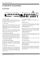
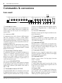
Controls & Connections
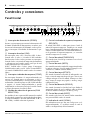
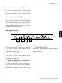
Front Panel
1
POWER Switch
Press this switch to power up the GC2020C. The power indi-
cator lights up. To power down the GC2020C, press this
switch again. The power indicator goes out.
2
LINK switch
This turns Link ON and OFF. When Link is ON, the LED
indicator lights up. Press the switch once again to turn it
OFF. When Link is ON, compression and limiting is applied
equally to both channels, so that a stereo signal can be pro-
cessed correctly.
NOTE: When using Link, set the COMP switch on both
channels to ON. And set the INPUT control and COMP
RATIO control on both channels to the same values.
3
COMP switch & indicator
This switch determines whether the compressor/limiter is
active, or bypassed. When this switch is ON, the LED indi-
cator lights up, and the compressor/limiter circuit is active.
When it is OFF, the indicator is OFF, and the compres-
sor/limiter circuit is completely bypassed, so the input signal
is sent straight to the output jack.
4
GAIN REDUCTION meter
This five-segment LED meter shows the amount of gain
reduction that is being applied by the compressor/limiter.
The LEDs indicate 0 dB, –4 dB, –8 dB, –16 dB, and –24 dB of
gain reduction.
5
EXP GATE control & indicator
The EXP GATE control is used to set the threshold level of
the expander gate. When this control is turned hard left, the
gate function is OFF. The LED above the EXP GATE control
shows the operation of the expander gate, and light up when
the gate is closed.
6
THRESHOLD control
This sets the level at which the compressor/limiter begins to
take effect.
7
RATIO control
This determines the amount of compression that is applied
to signals that exceed the threshold level. The range is from 1
(1:1 ratio) to infinity (infinity:1 ratio).
8
ATTACK control
This determines the speed (in milliseconds) with which
compression begins after a signal exceeding the threshold is
detected. The range is from 0.2 msec (very fast attack time)
to 20 msec (relatively slow attack).
9
RELEASE control
This determines the speed at which compression is removed
after the signal falls below the threshold level. The range
from 50 msec to 2 sec.
0
INPUT control
This controls the input level. A wide range of input signals
can be accommodated.
A
SIGNAL indicator
This indicator shows that a signal is present in the compres-
sor/limiter. It lights up when the output signal is 13 dB
below the nominal level.
B
PEAK indicator
This indicator shows that a signal is about to clip. It lights up
when the output signal is 3 dB below the clip point. Adjust
the OUTPUT control so that this indicator just lights up at
the loudest signals.
COMP
GAIN
REDUCTION
0
–4
–8
–16
–24
EXP GATE THRESHOLD RATIO ATTACK RELEASE INPUT OUTPUT
CHANNEL A CHANNEL B
SIGNAL PEAK
GAIN
REDUCTION
0
–4
–8
–16
–24
EXP GATE THRESHOLD RATIO ATTACK RELEASE INPUT OUTPUT
SIGNAL PEAK
LINK COMP
ON OFF
POWER
0 10 0 10 0 10 0 10
1
2
48
20
00
0.2
1
35
10
20
0.05
0.1
0.3 0.5
1
2
0 10 0 10 0 10 0 10
1
2
48
20
00
0.2
1
35
10
20
0.05
0.1
0.3 0.5
1
2
secms
secms
10C98765432
BA

Rear Panel
7
GC2020C Compressor/Limiter Owner’s Manual
English
C
OUTPUT control
This controls the output level. When the input signal is
compressed by the compressor/limiter, it may appear to
have diminished in volume. This knob adjusts the level of
the signal that has been processed by the compressor/lim-
iter. While turning the COMP switch ON/OFF, adjust the
OUTPUT control so that the volume of the bypassed and
processed signals is the same.
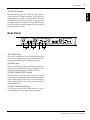
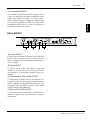
Rear Panel
D
OUTPUT jacks
These are the output jacks. Three-pin XLR type connectors
(male) and 1/4" phone jacks are provided. Both types are
balanced. Nominal impedance is 600 ohms for both.
E
INPUT jacks
These are the input jacks. Three-pin XLR type connectors
(female) and 1/4" phone jacks are provided. Both types are
balanced. Nominal impedance is 600 ohms for both.
F
SIDE CHAIN INT/EXT switch
This switch selects the signal source for the circuit that
detects the point at which the compressor/limiter is applied.
With a setting of INT, the detector uses the channel signal.
With a setting of EXT, the detector uses the signal from the
SIDE CHAIN IN jack.
G
SIDE CHAIN IN/OUT jack
These jacks are used to split the input signal, or to use an
external signal as the trigger for the compressor/limiter.
CHANNEL ACHANNEL B
OUT
IN
INT EXT
KEY
OUT
IN
INT EXT
KEY
INPUT
+4dB
OUTPUT
+4dB
INPUT
+4dB
OUTPUT
+4dB
SIDECHAIN SIDECHAIN
DEFG

8
Specifications
GC2020C Compressor/Limiter Owner’s Manual
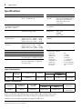
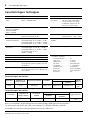
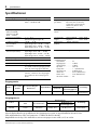
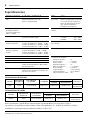
Specifications
Input Characteristics
Output Characteristics
In these specifications, when dB represents a specific voltage, 0 dB is referenced to 0.775 Vrms.
XLR type connectors and phone jacks (TRS) are balanced. (T=HOT, R=COLD, S=GND)
Sensitivity is the level required to produce an output of +4 dB (1.23 V).
Frequency Response 0
+1
dB 20 Hz— 20 kHz @+4 dB Link OFF/ON
Total Harmonic Distortion Less than 0.05% (THD + N)
20 Hz — 20 kHz @+4 dB
Controls
(per CH.)
Input Level, Output Level,
Exp. Gate (with ON/OFF switch),
Comp. Ratio, Threshold Level,
Attack Time, Release Time,
Comp switch
Hum & Noise (Average,
Rs=600
Ω
) (Measured with
BPF 20 Hz — 20 kHz)
–85 dB Power
Consumption
20W
Compression Ratio 1 : 1 —
∞
: 1
(Maximum limiting 32 dB)
Power
Requirement
USA and Canada
120 V 60 Hz
GENERAL
230 V 50 Hz
Compressor/Limiter
Threshold Level
+20 dB — –35 dB
(Input Control at 0 : +20 dB — +5 dB)
(Input Control at 5 : +20 dB — –20 dB)
(Input Control at 10 : +5 dB — –35 dB)
Dimensions
(W
×
H
×
D)
480
×
49.4
×
246mm
Expander Noise Gate
Threshold
+0 dB — –80 dB
(Input Control at 0 : 0 dB — –40 dB)
(Input Control at 5 : –25 dB — –65 dB)
(Input Control at 10 : –40 dB — –80 dB)
Weight 3.2kg
Attack Time 0.2 ms — 20 ms
* Measurement conditions
Link switch............................OFF
Input Level ............................5 (center)
Output Level .........................5 (center)
Exp. Gate..............................switch OFF
Comp. Ratio.......................... 1 : 1 (minimum)
Threshold Level .....................0 (minimum)
Attack Time........................... 0.2 ms (minimum)
Release Time .........................50 ms (minimum)
Key switch.............................INT
Release Time 50 ms — 2.0s
Gain Reduction 5 Segment LED Meter
Peak Indicators Red LED on each channel lights up when
the output signal is 3 dB below clipping.
Signal Indicators Green LED on each channel lights up
when the output signal is 17 dB below
the nominal level.
Connection
Actual Load
Impedance
For Use With Nominal Sensitivity
Input level
Connectors
Nominal
Maximum Before
Clipping
INPUT 15 kΩ 600 Ω Lines +4 dB (1.23 V) +4 dB (1.23 V) +20 dB (7.75 V)
XLR-3-31 Type
Phone Jack
Connection
Actual Source
Impedance
For Use With
Nominal
Output Level
Connectors
Nominal
Maximum Before
Clipping
OUTPUT 150 Ω 600 Ω Lines +4 dB (1.23 V) +20 dB (7.75 V)
XLR-3-32 Type
Phone Jack
–3

Specifications 9
GC2020C Compressor/Limiter Owner’s Manual
English
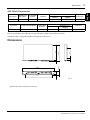
SIDE CHAIN Characteristics
In these specifications, when dB represents a specific voltage, 0 dB is referenced to 0.775 Vrms.
Sensitivity is the level required to produce an output of +4 dB (1.23 V)
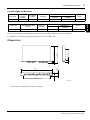
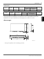
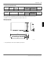
Dimensions
• Specifications subject to change without notice.
Connection
Actual Load
Impedance
For Use With
Nominal
Sensitivity
Input Level
Connectors
Nominal
Maximum Before
Clipping
SIDE CHAIN IN 27 kΩ 600 Ω Lines +4 dB (1.23 V) +4 dB (1.23 V) +20 dB (7.75 V) phono
Connection Actual Source Impedance
For Use With
Nominal
Output Level
Connectors
Nominal
Maximum Before
Clipping
SIDE CHAIN OUT 600 Ω 10 kΩ Lines +4 dB (1.23 V) +20 dB (7.75 V) phono
H:49.4
2
16
44
5.4
402
W:480
228
D:246
30
150
Unit : mm

10 Block Diagram
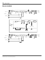
GC2020C Compressor/Limiter Owner’s Manual
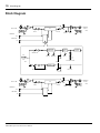
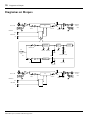
Block Diagram
CHANNEL B
CHANNEL B
OUT
IN
INPUT +4dB
SIDECHAIN
VCA
OUTPUTINPUT
HA
+4dB
OUTPUT
SIGNAL PEAK
COMP
(to CH B)
(to CH B)
-24
-16
-8
-4
0
LINK
GAIN REDUCTION
EXP GATE
GENERATOR
ENVELOPE
RELEASEATTACK
SHIFTER
VOLTAGE
RATIO
RATIO
COMP
EXT
INT
KEY
EXP GATE
f(x)=1/x
THRESHOLD
EXP GATE
COMP
PEAKSIGNAL
OUTPUT
+4dB
CHANNEL A
CHANNEL A
HA
INPUT OUTPUT
VCA
SIDECHAIN
INPUT +4dB
IN
OUT

i
GC2020C Compresseur/Limiteur Mode d’emploi
Français
COMPRESSOR/LIMITER
GC2020C
Mode d’emploi
Bienvenue au Compresseur/Limiteur GC2020C
Avant-propos
Merci d’avoir porté votre choix sur un Compressor/Limiter
GC2020C de Yamaha. Le GC2020C est un compresseur/lim-
iteur professionnel à deux canaux qui convient tant pour les
enregistrements audio que pour des tâches de sonorisation.
Le GC2020C vous propose un grand registre de fonctions de
contrôle, vous permettant ainsi de vous confectionner exact-
ement le son requis au moyen des paramètres de compres-
sion et de d’écrétage Doté d’une fonction expandeur/Gate, il
permet en outre d’éliminer du souffle et tout autre bruit de
fond qui risqueraient d’être amplifiés par le compres-
seur/écrêteur.
La compression du GC2020C peut être utilisée pour conférer
plus de “punch” au mix final, voire pour éviter de trop
importantes différences de niveau. Un soupçon de compres-
sion rendra le chant plus égal, car nous savons tous qu’un
chanteur a tendance ‘å bouger en chantant. En gros, un com-
presseur sert à réduire la dynamique d’un signal. Cette tech-
nique permet en outre de maîtriser des instruments tels que
des guitares, des basses ou un piano acoustique. Par ailleurs,
une grosse caisse, caisse claire, voire des toms, sans compres-
seur ont tendance à manquer d’impact. La fonction
d’écrétage, par contre, vous aidera à protéger vos enceintes
contre des signaux quelque peu intempestifs, ce qui cause
parfois des dégâts.
Que vous ayez besoin d’un “correcteur de signal”, d’un
dompteur ou d’un instrument créatif, le GC2020C n’est pas
prêt à vous décevoir. Vous avez fait un excellent choix.
Afin de tirer pleinement parti de votre GC2020C, nous vous
conseillons de lire ce manuel dans son entièreté et de le con-
server en lieu sûr.

ii
GC2020C Compresseur/Limiteur Mode d’emploi
Précautions
Evitez toute exposition à une chaleur,
une humidité, une quantité de
poussière et de vibrations excessives
Evitez de placer l’appareil dans un lieu exposé à des tempéra-
tures élevées ou une forte humidité (évitez la proximité de
radiateurs, poêles, l’exposition au soleil, etc.). De même, les
endroits poussiéreux ou sujets à des vibrations sont à proscr-
ire pour éviter tout endommagement.
Evitez les chocs
Des chocs violents peuvent endommager l’appareil.
Maniez-le avec soin.
Veillez à laisser assez d’espace autour de l’appareil pour
garantir une bonne ventilation.
Gardez au moins un espace de 10 cm entre l’arrière de l’appa-
reil et le mur. Cela évitera toute accumulation interne de
chaleur qui risquerait de provoquer une surchauffe de
l’appareil et éventuellement un incendie.
N’ouvrez pas le boîtier de l’appareil
et n’essayez pas de le réparer ou le
modifier vous-même.
Ce produit ne contient aucune pièce réparable par l’utili-
sateur. Adressez-vous pour tout entretien ou réparation à un
SAV agréé par Yamaha. Si vous ouvrez l’appareil et/ou
touchez aux circuits internes, vous perdez le bénéfice de la
garantie.
Assurez-vous que l’appareil est hors
tension avant d’effectuer ou de
supprimer des connexions
Mettez toujours les appareils concernés hors tension avant de
brancher et de débrancher des câbles. C’est vital pour éviter
d’endommager l’appareil ainsi que tout autre matériel qui y
est relié.
Maniez les câbles avec précaution
Branchez et débranchez toujours les câble (ainsi que le cor-
don d’alimentation) en tirant sur la prise et non sur le câble.
Nettoyez avec un chiffon doux et sec
N’utilisez jamais de solvants tels que de l’essence ou de la
térébenthine pour nettoyer l’appareil. Essuyez-le avec un
chiffon doux et sec.
Utilisez toujours une source d’alimen-
tation adéquate
Assurez-vous que la tension spécifiée à l’arrière de l’appareil
correspond à celle de vos prises secteur:
Modèle USA & canadien: 120V CA, 60 Hz
Modèle général: 230V CA, 50 Hz
Modèle pour la Grande-Bretagne: 240V CA, 50 Hz
Sommaire
Qu’est-ce qu’un Compresseur/Limiteur? . . 1
Fonctions du Compresseur/Limiteur . . . 1
Paramètres du Compresseur/Limiteur . . 2
Réglage du Compresseur/Limiteur . . . . . 4
Qu’est-ce qu’un Expandeur/Gate? . . . . . . . 5
Réglage de l’Expandeur/Gate . . . . . . . . . 5
Commandes & connexions . . . . . . . . . . . . 6
Face avant . . . . . . . . . . . . . . . . . . . . . . . 6
Face arrière . . . . . . . . . . . . . . . . . . . . . . 7
Caractéristiques techniques . . . . . . . . . . 8
Dimensions . . . . . . . . . . . . . . . . . . . . . . 9
Schéma . . . . . . . . . . . . . . . . . . . . . . . . 10

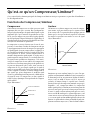
Qu’est-ce qu’un Compresseur/Limiteur?
1
GC2020C Compresseur/Limiteur Mode d’emploi
Français
Qu’est-ce qu’un Compresseur/Limiteur?
Cette section décrit les fonctions principales du Compresseur/Limiteur ainsi que ses paramètres, sa procédure d’installation et
les effets Expandeur/Gate.
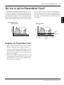
Fonctions du Compresseur/Limiteur
Compresseur
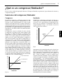
Généralement, un compresseur sert à faire passer un signal
important dans un espace restreint. Plus spécifiquement,
lorsque la plage dynamique du signal audio original est plus
importante que ce que le matériel de reproduction est capa-
ble de gérer, un compresseur peut réduire la plage dynami-
que du signal pour l’adapter aux limites de l’appareillage de
reproduction ou d’enregistrement. Cela doit bien sûr se faire
sans ajouter de distorsion au signal même.
La compression se mesure selon un taux: le taux de com-
pression. Ce taux donne l’étendue du changement subi par
le signal apparaissant à la sortie du compresseur par rapport
au signal original. Si aucune compression n’est appliquée et
si le signal d’entrée double de niveau, le signal de sortie dou-
blera également de niveau, suivant scrupuleusement le
moindre changement du signal original. Ce réglage corres-
pond à un taux de compression de 1:1 (un changement de 1
du signal d’entrée produira un changement 1 à la sortie),
soit pas de compression. Si vous utilisez de la compression,
vous observerez un changement plus petit du signal à la sor-
tie pour un changement égal à l’entrée. Ainsi, un taux de
compression de 2:1, par exemple, signifie que le signal de
sortie ne sera modifié que de moitié par rapport au signal
d’entrée. Exprimé en décibels, un taux de compression de
20:1 signifie que qu’un changement de 20 dB du signal
d’entrée ne produirait qu’un changement de 1 dB du niveau
du signal de sortie. Un compresseur est donc capable de
réduire la plage dynamique d’un signal audio de n’importe
quelle manière.
Voyez “Illustration 1”.
Illustration 1
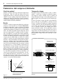
Limiteur
Un limiteur est en fait un compresseur à taux de compres-
sion extrême, réglé pour n’affecter que les signaux au-delà
d’un certain seuil. C’est particulièrement pratique pour ne
limiter que les crêtes qui excèdent la capacité de traitement
du matériel en question sans toucher au reste du signal.
Voyez “Illustration 2”.
Illustration 2
Imaginons que nous voulions limiter les crêtes d’un pro-
gramme à un maximum de 0 dB afin d’éviter la saturation et
la distorsion lors d’un enregistrement. Réglons d’abord le
niveau “seuil” sur 0 dB (le niveau seuil est le niveau qui
enclenche le limiteur lorsque le signal d’entrée l’atteint).
Ensuite, il faut régler la compression maximale (ou presque)
disponible —
∞
:1 (compression infinie). La compression
infinie signifie qu’il n’y a absolument aucun changement du
niveau de sortie quels que soient les changements du niveau
d’entrée. Le signal sera donc inchangé tant qu’il reste sous le
niveau seuil (0 dB) tandis que les signaux dépassant ce seuil
seront émis au niveau seuil mais n’iront pas plus haut. Dans
ce cas, aucun signal excédant 0 dB n’apparaîtra à la sortie du
limiteur. Le signal audio n’est donc pas modifié, il garde sim-
plement son niveau moyen (r.m.s.) dans des limites définies.
1:1 PAS DE COMPRESSION
COMPRESSION 2:1
Threshold (seuil)
Niveau du signal de sortie
Niveau du signal entrant
COMPRESSION
(dB)
(dB)
0
Seuil d’écrétage
(Limiter)
Niveau du signal de sortie
Niveau du signal entrant
ECRETEUR (LIMITER)
0
(dB)
(dB)

2
Paramètres du Compresseur/Limiteur
GC2020C Compresseur/Limiteur Mode d’emploi
Paramètres du Compresseur/Limiteur
Niveau seuil (Threshold)
Le seuil est le niveau du signal auquel la compression ou la
limitation commence. Tous les signaux dont le niveau reste
inférieur au seuil sont transmis tels qu’ils ont été reçus, sans
compression ni limitation. Les signaux dont le niveau
dépasse ce seuil sont comprimés ou limités en fonction des
réglages des paramètres RATIO, ATTACK et RELEASE.
Taux (Ratio)
Il s’agit de la quantité de compression appliquée aux signaux
dont le niveau excède le niveau choisi par la commande
THRESHOLD (seuil). Le taux de compression est exprimé
en termes de quantité de changement du niveau du signal
d’entrée par rapport à la quantité de changement du niveau
du signal de sortie. Un taux élevé signifie beaucoup de com-
pression. Un taux de compression de 1:1, par contre,
n’entraîne aucune compression; un changement de 1 du
niveau du signal d’entrée impliquera un changement de 1
pour le niveau du signal de sortie tandis qu’un taux de com-
pression de 2:1 implique que si le niveau du signal d’entrée
change selon une certaine valeur (2), le changement du
niveau du signal de sortie sera de moitié moindre (1). Une
option extrême consiste à choisir un taux de compression de
∞
:1 (infini sur un), ce qui signifie que le niveau du signal de
sortie restera constant. Ce réglage du taux de compression,
∞
:1, est utilisé la plupart du temps pour des écrétages sévè-
res, lorsque le niveau du signal ne peut en aucun cas dépas-
ser une valeur spécifique (souvent 0 dB). Des taux de
compression extrêmement élevés du type de 20:1 peuvent
ajouter du Sustain à certains sons d’instruments (tels que la
guitare électrique et la basse) et créer des sons de percussion
contemporains. Des taux de compression plus bas (allant de
moins de 2:1 à 8:1) sont pratiques pour rendre le chant plus
uniforme et minimiser les variations de niveau qui se pro-
duisent lorsqu’un orateur ou un chanteur se rapproche et
s’éloigne du microphone.
Illustration 3
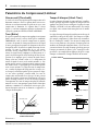
Temps d’attaque (Attack Time)
Le temps d’attaque détermine le temps qu’il faut (en millise-
condes) pour que la quantité complète de compression soit
appliquée une fois le niveau seuil dépassé. La plage de temps
d’attaque (ATTACK) va de 0,2 millisecondes, une attaque
très rapide, à une version relativement plus lente de 20 mil-
lisecondes.
Le réglage du temps d’attaque dépend largement du type de
signal traité et du type d’effet désiré. Une attaque très rapide,
par exemple, comprimera le début d’une note instrumen-
tale et le rendra plus “étouffée”. Des niveaux de compression
élevés servent parfois avec des guitares électriques pour leur
attribuer un Sustain plus important. Dans ce cas, il vaut sou-
vent mieux choisir un temps d’attaque plus long pour que
l’attaque percutante de la guitare “passe” avant que la com-
pression ne soit complètement appliquée. Réglez le temps
d’attaque en fonction de l’attaque naturelle du son traité.
Illustration 4
+30
+20
+10
0
–10
–20
–30
–40
–50
Threshold (seuil)
Niveau du signal de sortie (dB)
Niveau du signal entrant (dB)
COMPRESSION RATIOS
–60–70 +30–50 –40 –30 –20 –10 0 +10 +20
1:1
2:1
4:1
8:1
20:1
:1
Attack= 0
Signal entrant
Attack rapide
Temps d’attaque
Attack lente
Temps d’attaqu
Fonction ATTACK

Paramètres du Compresseur/Limiteur
3
GC2020C Compresseur/Limiteur Mode d’emploi
Français
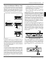
Temps de relâchement (Release Time)
Le temps de relâchement détermine le temps qu’il faut pour
que la compression revienne à zéro une fois que le signal audio
tombe sous le niveau seuil. La plage du temps de relâchement
(RELEASE) va de 50 millisecondes (0,05 secondes) à 2 secon-
des. Tout comme la commande ATTACK, la commande
RELEASE dépend du type de signal traité et de l’effet désiré.
Illustration 5
La principale raison d’être de cette commande est que si la
compression s’arrête brutalement au moment où le signal
retombe sous le niveau seuil, cela provoquerait un change-
ment abrupt et peu naturel du niveau du signal audio, sur-
tout avec des instruments qui ont un temps de chute long et
doux. Sauf pour effet spécial, réglez ce paramètre RELEASE
en fonction du signal à traiter.
Lien (Link)
Cette fonction permet de coupler le Compresseur/Limiteur
du canal A et du canal B. Lorsqu’un Compresseur/Limiteur
est utilisé pour traiter un signal stéréo, le recours à deux
canaux de compression indépendants risque de faire osciller
l’image stéréo de manière instable et de produire un effet
fort peu naturel.Si les deux canaux sont liés, cependant, il est
possible d’appliquer la même compression de part et d’autre
et de préserver ainsi l’image stéréo. Lorsque le paramètre
Link est ON (activé), les paramètres des deux canaux sont
liés comme suit.
• Le Compresseur/Limiteurs se sert du réglage du niveau
seuil (Threshold) du canal dont la valeur est la plus élevée.
• L’expandeur/noise gate se sert du niveau seuil (Thres-
hold) du canal dont la valeur est la plus basse.
• Pour les temps d’attaque (Attack) et de relâchement
(Release), le canal ayant le réglage le plus rapide (le plus
court) détermine l’autre.
Déclencheur externe (External Trigger)
Les Compresseur/Limiteurs commencent normalement la
compression lorsque le niveau d’entrée dépasse le niveau
seuil. Cependant, il est également possible d’utiliser un autre
signal que le signal d’entrée comme déclencheur. Le
GC2020C dispose d’une borne SIDE CHAIN OUT qui per-
met de dédoubler le signal d’entrée et de l’envoyer à un
appareil externe. La borne SIDE CHAIN IN permet au
signal d’un appareil externe de contrôler le Compres-
seur/Limiteur. L’utilisation d’un déclencheur externe per-
met un contrôle renforcé du GC2020C.
Par exemple, si vous branchez la borne SIDE CHAIN OUT
du canal A à la borne SIDE CHAIN IN du canal B (celui-ci
sera donc piloté par un déclencheur externe, le canal A en
l’occurrence), le Compresseur/Limiteur n’aura un effet sur le
signal du canal B que lorsque le signal du canal A excède le
seuil. C’est une façon simple de produire l’effet Ducking
(abaissement) que les DJ ou les annonceurs utilisent pour
diminuer automatiquement le volume de la musique
lorsqu’ils parlent.
En branchant un égaliseur entre les bornes SIDE CHAIN
OUT et SIDE CHAIN IN, en accentuant la région des
3–5 kHz et en réglant ce canal de sorte à ce qu’il fonctionne
avec un déclencheur externe, vous pouvez appliquer un effet
qui supprime le sifflement des “s” (De-Esser) que le Com-
presseur n’applique que sur les sons qui contiennent le son
“s”.).
Release= 0
Release rapide
Release lente
Temps de
relâchement
Signal entrant
Temps de relâchement
Fonction RELEASE
CHANNEL A
OUT
IN
INT EXT
KEY
OUT
IN
INT EXT
KEY
INPUT
+4dB
OUTPUT
+4dB
SIDECHAIN SIDECHAIN
INT EXT
CHANNEL A
OUT
IN
INT EXT
KEY
INPUT
+4dB
OUTPUT
+4dB
SIDECHAIN
INT EXT
Egaliseur

4
Réglage du Compresseur/Limiteur
GC2020C Compresseur/Limiteur Mode d’emploi
Réglage du Compresseur/Limiteur
1. Réglez les commandes INPUT et OUTPUT au centre.
2. Réglez le niveau seuil (Threshold) et le taux (Ratio) en
fonction de l’usage que vous allez en faire.
3. Réglez la commande OUTPUT de sorte que le témoin
PEAK ne s’allume que pour les niveaux les plus élevés.
4. Réglez les temps d’attaque et de relâchement (Attack et
Release) comme vous l’entendez.

Qu’est-ce qu’un Expandeur/Gate?
5
GC2020C Compresseur/Limiteur Mode d’emploi
Français
Qu’est-ce qu’un Expandeur/Gate?
Le GC2020C comprend un Expandeur/Gate qui est indé-
pendant du Compresseur/Limiteur. L’Expandeur/Gate est
une fonction qui élimine tout bourdonnement ou bruit de
fond audibles lors des parties silencieuses du programme. Sa
fonction consiste à bloquer le passage (Gate) pour couper le
signal de sortie lorsque le signal d’entrée tombe sous un
niveau spécifié (le niveau seuil du Gate). Normalement, ce
niveau est inférieur au niveau le plus bas de la portion musi-
cale afin de laisser passer le signal. Le bourdonnement ou
bruit dont le niveau est plus bas que celui de la musique sera
donc éliminé.
Réglage de l’Expandeur/Gate
1. Réglez le niveau d’entrée de sorte à ce que le témoin
PEAK ne s’allume que pour les signaux les plus forts.
2. Sans jouer de l’instrument, augmentez progressivement
la valeur du niveau seuil pour le Gate et réglez-le sur une
position légèrement plus élevée que le point auquel le
bruit n’est plus audible.
3. Faites entrer un signal et vérifiez que sa chute n’est pas
coupée de manière non naturelle pour les notes jouées le
plus doucement. Si le son est coupé, diminuez légère-
ment la valeur Gate Threshold.
Signal musical
Bruit de
fond
Bruit de
fond
Temps
Niveau
• Fonction EXP GATE
SIGNAL ENTRANT
Signal musical
Ces signaux
sont étouffés.
Ces signaux
sont étouffés.
Ces signaux
sont étouffés.
Seuil de la
fonction
Expander/Gate
Temps
Niveau
SIGNAL DE SORTIE
Pagina se încarcă ...
Pagina se încarcă ...
Pagina se încarcă ...
Pagina se încarcă ...
Pagina se încarcă ...
Pagina se încarcă ...
Pagina se încarcă ...
Pagina se încarcă ...
Pagina se încarcă ...
Pagina se încarcă ...
Pagina se încarcă ...
Pagina se încarcă ...
Pagina se încarcă ...
Pagina se încarcă ...
Pagina se încarcă ...
Pagina se încarcă ...
Pagina se încarcă ...
Pagina se încarcă ...
Pagina se încarcă ...
Pagina se încarcă ...
Pagina se încarcă ...
Pagina se încarcă ...
Pagina se încarcă ...
Pagina se încarcă ...
Pagina se încarcă ...
Pagina se încarcă ...
Pagina se încarcă ...
Pagina se încarcă ...
Pagina se încarcă ...
Pagina se încarcă ...
-
 1
1
-
 2
2
-
 3
3
-
 4
4
-
 5
5
-
 6
6
-
 7
7
-
 8
8
-
 9
9
-
 10
10
-
 11
11
-
 12
12
-
 13
13
-
 14
14
-
 15
15
-
 16
16
-
 17
17
-
 18
18
-
 19
19
-
 20
20
-
 21
21
-
 22
22
-
 23
23
-
 24
24
-
 25
25
-
 26
26
-
 27
27
-
 28
28
-
 29
29
-
 30
30
-
 31
31
-
 32
32
-
 33
33
-
 34
34
-
 35
35
-
 36
36
-
 37
37
-
 38
38
-
 39
39
-
 40
40
-
 41
41
-
 42
42
-
 43
43
-
 44
44
-
 45
45
-
 46
46
-
 47
47
-
 48
48
-
 49
49
-
 50
50


Yamaha GC2020C Manualul proprietarului
- Categorie
- Compresoare de aer
- Tip
- Manualul proprietarului
în alte limbi
- Türkçe: Yamaha GC2020C El kitabı
- français: Yamaha GC2020C Le manuel du propriétaire
- čeština: Yamaha GC2020C Návod k obsluze
- русский: Yamaha GC2020C Инструкция по применению
- English: Yamaha GC2020C Owner's manual
- polski: Yamaha GC2020C Instrukcja obsługi
- Deutsch: Yamaha GC2020C Bedienungsanleitung
- 日本語: Yamaha GC2020C 取扱説明書
- italiano: Yamaha GC2020C Manuale del proprietario
- español: Yamaha GC2020C El manual del propietario
- svenska: Yamaha GC2020C Bruksanvisning
- dansk: Yamaha GC2020C Brugervejledning
- português: Yamaha GC2020C Manual do proprietário
- Nederlands: Yamaha GC2020C de handleiding
Lucrări conexe
-
Yamaha GC2020BII Manualul proprietarului
-
-
Yamaha QL1 Manual de utilizare
-
Yamaha QL1 Manual de utilizare
-
Yamaha CL1 Manual de utilizare
-
-
-
-
-