Yamaha RX-V863 Manualul proprietarului
- Categorie
- Receptoare AV
- Tip
- Manualul proprietarului

YAMAHA ELECTRONICS CORPORATION, USA
6660 ORANGETHORPE AVE., BUENA PARK, CALIF. 90620, U.S.A.
YAMAHA CANADA MUSIC LTD.
135 MILNER AVE., SCARBOROUGH, ONTARIO M1S 3R1, CANADA
YAMAHA ELECTRONIK EUROPA G.m.b.H.
SIEMENSSTR. 22-34, 25462 RELLINGEN BEI HAMBURG, GERMANY
YAMAHA ELECTRONIQUE FRANCE S.A.
RUE AMBROISE CROIZAT BP70 CROISSY-BEAUBOURG 77312 MARNE-LA-VALLEE CEDEX02, FRANCE
YAMAHA ELECTRONICS (UK) LTD.
YAMAHA HOUSE, 200 RICKMANSWORTH ROAD WATFORD, HERTS WD18 7GQ, ENGLAND
YAMAHA SCANDINAVIA A.B.
J A WETTERGRENS GATA 1, BOX 30053, 400 43 VÄSTRA FRÖLUNDA, SWEDEN
YAMAHA MUSIC AUSTRALIA PTY. LTD.
LEVEL 1, 99 QUEENSBRIDGE STREET, SOUTHBANK, VIC 3006, AUSTRALIA
©
2008 All rights reserved.
RX-V863
Printed in Malaysia WN24780
RX-V863
AV Receiver
Ampli-tuner audio-vidéo
OWNER’S MANUAL
MODE D’EMPLOI
BEDIENUNGSANLEITUNG
BRUKSANVISNING
GEBRUIKSAANWIJZING
ИНСТРУКЦИЯ ПО ЭКСПЛУАТАЦИИ
G
RX-V863_G-cv.mif Page 1 Thursday, January 17, 2008 5:05 PM
Black process 45.0° 240.0 LPI

CAUTION: READ THIS BEFORE OPERATING YOUR UNIT.
En
1 To assure the finest performance, please read this manual
carefully. Keep it in a safe place for future reference.
2 Install this sound system in a well ventilated, cool, dry, clean
place – away from direct sunlight, heat sources, vibration,
dust, moisture, and/or cold. Allow ventilation space of at least
30 cm on the top, 20 cm on the left and right, and 20 cm on
the back of this unit.
3 Locate this unit away from other electrical appliances, motors,
or transformers to avoid humming sounds.
4 Do not expose this unit to sudden temperature changes from
cold to hot, and do not locate this unit in an environment with
high humidity (i.e. a room with a humidifier) to prevent
condensation inside this unit, which may cause an electrical
shock, fire, damage to this unit, and/or personal injury.
5 Avoid installing this unit where foreign objects may fall onto
this unit and/or this unit may be exposed to liquid dripping or
splashing. On the top of this unit, do not place:
– other components, as they may cause damage and/or
discoloration on the surface of this unit.
– burning objects (i.e. candles), as they may cause fire,
damage to this unit, and/or personal injury.
– containers with liquid in them, as they may fall and liquid
may cause electrical shock to the user and/or damage to
this unit.
6 Do not cover this unit with a newspaper, tablecloth, curtain,
etc. in order not to obstruct heat radiation. If the temperature
inside this unit rises, it may cause fire, damage to this unit,
and/or personal injury.
7 Do not plug in this unit to a wall outlet until all connections
are complete.
8 Do not operate this unit upside-down. It may overheat,
possibly causing damage.
9 Do not use force on switches, knobs and/or cords.
10 When disconnecting the power cable from the wall outlet,
grasp the plug; do not pull the cable.
11 Do not clean this unit with chemical solvents; this might
damage the finish. Use a clean, dry cloth.
12 Only voltage specified on this unit must be used. Using this
unit with a higher voltage than specified is dangerous and may
cause fire, damage to this unit, and/or personal injury. Yamaha
will not be held responsible for any damage resulting from use
of this unit with a voltage other than specified.
13 To prevent damage by lightning, keep the power cord and
outdoor antennas disconnected from a wall outlet or the unit
during a lightning storm.
14 Do not attempt to modify or fix this unit. Contact qualified
Yamaha service personnel when any service is needed. The
cabinet should never be opened for any reasons.
15 When not planning to use this unit for long periods of time
(i.e. vacation), disconnect the AC power plug from the wall
outlet.
16 Install this unit near the AC outlet and where the AC power
plug can be reached easily.
17 Be sure to read the “Troubleshooting” section on common
operating errors before concluding that this unit is faulty.
18 Before moving this unit, press
L
SYSTEM OFF to set this
unit to the standby mode, and then disconnect the AC power
plug from the AC wall outlet.
19 VOLTAGE SELECTOR (Asia and General models only)
The VOLTAGE SELECTOR on the rear panel of this unit
must be set for your local main voltage BEFORE plugging
into the AC wall outlet. Voltages are:
Asia model ............................ 220/230–240 V AC, 50/60 Hz
General model ........ 110/120/220/230–240 V AC, 50/60 Hz
20 The batteries shall not be exposed to excessive heat such as
sunshine, fire or like.
21 Excessive sound pressure from earphones and headphones can
cause hearing loss.
■ For U.K. customers
If the socket outlets in the home are not suitable for the plug
supplied with this appliance, it should be cut off and an
appropriate 3 pin plug fitted. For details, refer to the
instructions described below.
The plug severed from the mains lead must be destroyed, as a
plug with bared flexible cord is hazardous if engaged in a live
socket outlet.
■ Special Instructions for U.K. Model
Caution: Read this before operating your unit.
WARNING
TO REDUCE THE RISK OF FIRE OR ELECTRIC
SHOCK, DO NOT EXPOSE THIS UNIT TO RAIN OR
MOISTURE.
As long as this unit is connected to the AC wall outlet, it is
not disconnected from the AC power source even if you
turn off this unit by
L
SYSTEM OFF. In this state, this
unit is designed to consume a very small quantity of
power.
Note
IMPORTANT
THE WIRES IN MAINS LEAD ARE COLOURED IN
ACCORDANCE WITH THE FOLLOWING CODE:
Blue: NEUTRAL
Brown: LIVE
As the colours of the wires in the mains lead of this apparatus
may not correspond with the coloured markings identifying
the terminals in your plug, proceed as follows:
The wire which is coloured BLUE must be connected to the
terminal which is marked with the letter N or coloured
BLACK. The wire which is coloured BROWN must be
connected to the terminal which is marked with the letter L or
coloured RED.
Making sure that neither core is connected to the earth
terminal of the three pin plug.
This symbol mark is according to the EU
directive 2002/96/EC.
This symbol mark means that electrical
and electronic equipment, at their end-of-
life, should be disposed of separately from
your household waste.
Please act according to your local rules
and do not dispose of your old products
with your normal household waste.

1 En
PREPARATIONINTRODUCTION
BASIC
OPERATION
ADVANCED
OPERATION
ADDITIONAL
INFORMATION
APPENDIX
English
Features ................................................................... 2
Supplied accessories .................................................. 2
Notice ....................................................................... 3
Getting started ........................................................ 4
Quick start guide .................................................... 5
Connections........................................................... 10
Optimizing the speaker setting
for your listening room (YPAO) ..................... 32
Using AUTO SETUP .............................................. 32
Selecting the SCENE templates........................... 37
Selecting the desired SCENE template
to the SCENE buttons.......................................... 37
Creating your original SCENE templates................ 40
Using the remote control for the SCENE feature .... 41
Playback ................................................................ 42
Basic procedure ....................................................... 42
Selecting the MULTI CH INPUT component......... 43
Selecting the front speaker set ................................. 43
Selecting audio input jacks (AUDIO SELECT)...... 44
Displaying the current status of this unit
on a video monitor............................................... 44
Using your headphones............................................ 45
Muting the audio output........................................... 45
Playing video sources in the background
of an audio source................................................ 45
Displaying the input source information ................. 46
Using the sleep timer ............................................... 47
Sound field programs.......................................... 48
Selecting sound field programs ............................... 48
Sound field program descriptions............................ 48
Enjoying unprocessed input sources
(Straight decoding mode) .................................... 51
Using audio features ............................................. 52
Adjusting the speaker level...................................... 52
Enjoying pure hi-fi sound ........................................ 52
Adjusting the tonal quality....................................... 52
FM/AM tuning ...................................................... 53
Overview.................................................................. 53
Basic tuning operations............................................ 53
Using station preset feature ..................................... 54
Radio Data System tuning
(Europe and Russia models only).................... 57
Selecting the Radio Data System program type
(PTY SEEK mode).............................................. 57
Using the enhanced other networks (EON)
data service .......................................................... 58
Displaying the Radio Data System information ...... 59
Using iPod™.......................................................... 60
Controlling iPod™................................................... 60
Using Bluetooth™ components ........................... 62
Pairing the Bluetooth™ adapter
and your Bluetooth™ component ....................... 62
Playback of the Bluetooth™ component................. 62
Recording .............................................................. 63
Advanced sound configurations...........................64
Changing sound field parameter settings................. 64
Selecting decoders ................................................... 70
Customizing this unit (MANUAL SETUP).........72
Using SET MENU................................................... 76
1 BASIC MENU...................................................... 77
2 VOLUME MENU ................................................ 81
3 SOUND MENU.................................................... 82
4 INPUT MENU...................................................... 85
5 OPTION MENU................................................... 88
Remote control features........................................92
Controlling this unit, a TV,
or other components ............................................ 92
Setting remote control codes ................................... 94
Programming codes from other remote controls ..... 96
Changing source names in the display window....... 97
Macro programming features .................................. 98
Clearing configurations ......................................... 101
Using multi-zone configuration..........................104
Connecting Zone 2................................................. 104
Controlling Zone 2................................................. 105
Advanced setup....................................................107
Using the advanced setup ...................................... 107
Troubleshooting...................................................111
Resetting the system............................................119
Glossary................................................................120
Sound field program information......................123
Specifications .......................................................124
Index.....................................................................126
(at the end of this manual)
Front panel................................................................i
Remote control ....................................................... ii
List of remote control codes ................................. iii
Contents
INTRODUCTION
PREPARATION
BASIC OPERATION
ADVANCED OPERATION
ADDITIONAL INFORMATION
APPENDIX
“
A
SPEAKERS” or “
5
DVD” (example) indicates the name
of the parts on the front panel or the remote control. Refer to
the attached sheet or the pages at the end of this manual for
the information about each position of the parts.

FEATURES
2 En
Built-in 7-channel power amplifier
◆ Minimum RMS output power
(20 Hz to 20 kHz, 0.06% THD, 8 Ω)
Front: 105 W + 105 W
Center: 105 W
Surround: 105 W + 105 W
Surround back: 105 W + 105 W
SCENE function
◆ Preset SCENE templates for various situations
◆ SCENE templates for customizing capability
◆ Controlling Yamaha SCENE control signal support
component (some models only) working with the SCENE
function
Sound field programs
◆ Proprietary Yamaha technology for the creation of sound
fields
◆ Compressed Music Enhancer mode
◆ Virtual CINEMA DSP
◆ SILENT CINEMA
Digital audio decoders
◆ Dolby TrueHD, Dolby Digital Plus decoder
◆ DTS-HD Master Audio, DTS-HD High Resolution Audio
decoder
◆ Dolby Digital/Dolby Digital EX decoder
◆ DTS/DTS-ES Matrix 6.1, Discrete 6.1, DTS 96/24 decoder
◆ Dolby Pro Logic/Dolby Pro Logic II/Dolby Pro Logic IIx
decoder
Radio tuners
◆ FM/AM tuning capability
◆ Radio Data System capability (Europe and Russia models
only)
HDMI™ (High-Definition Multimedia Interface)
◆ HDMI interface for standard, enhanced or
high-definition video as well as multi-channel digital audio
based on HDMI version 1.3a (HDMI is licensed by HDMI
Licensing LLC.)
– Automatic audio and video synchronization (lip sync)
information capability
– Deep Color video signal (30/36 bit) transmission capability
– “x.v.Color” video signal transmission capability
– High refresh rate and high resolution video signals
capability
– High definition digital audio format signals capability
◆ HDCP (High-bandwidth Digital Content Protection System)
licensed by Digital Content Protection, LLC.
◆ Analog video to HDMI digital video up-conversion
(composite video ↔ S-video ↔ component video → HDMI
digital video) capability for monitor out
◆ Analog video up-scaling from 480i (NTSC)/576i (PAL) or
480p/576p to 720p, 1080i or 1080p
DOCK terminal
◆ DOCK terminal to connect a Yamaha iPod universal dock
(such as YDS-10, sold separately) or Bluetooth adapter (such
as YBA-10, sold separately)
Other features
◆ YPAO (Yamaha Parametric Room Acoustic Optimizer) for
automatic speaker setup
◆ 192-kHz/24-bit D/A converter
◆ OSD (on-screen display) menus that allow you to optimize
this unit to suit your individual audiovisual system
◆ 5.1 or 7.1-channel additional input jacks for discrete multi-
channel input
◆ Component video input/output capability includes
(3 COMPONENT VIDEO INs and 1 MONITOR OUT)
◆ Digital video signal conversion (composite video ↔ S-video
↔ component video) capability for monitor out
◆ Pure Direct mode for pure hi-fi sound for all sources
◆ Adaptive dynamic range controlling capability
◆ Adaptive DSP effect level controlling capability
◆ iPod controlling capability
◆ Remote control with preset remote control codes, learning,
and macro capability
◆ Zone 2 custom installation facility
◆ Bi-amplification connection capability
◆ Sleep timer
Check that you received all of the following parts.
❏ Remote control
❏ Batteries (4) (AAA, R03, UM-4)
❏ Optimizer microphone
❏ AM loop antenna
❏ Indoor FM antenna
Features
Supplied accessories

Notice
3 En
INTRODUCTION
English
Manufactured under license from Dolby Laboratories.
“Dolby”, “Pro Logic”, and the double-D symbol are trademarks
of Dolby Laboratories.
Manufactured under license under U.S. Patent No’s:
5,451,942;5,956,674;5,974,380;5,978,762;6,226,616;6,487,535
& other U.S. and worldwide patents issued & pending. DTS is a
registered trademark and the DTS logos, Symbol, DTS-HD and
DTS-HD Master Audio are trademark of DTS, Inc. © 1996-2007
DTS, Inc. All Rights Reserved.
iPod™
“iPod” is a trademark of Apple Inc., registered in the U.S. and
other countries.
Bluetooth
™
Bluetooth is a registered trademark of the Bluetooth SIG and is
used by Yamaha in accordance with a license agreement.
“HDMI”, the “HDMI” logo and “High-Definition Multimedia
Interface” are trademarks or registered trademarks of HDMI
Licensing LLC.
x.v.Color™
“x.v.Color” is a trademark of Sony Corporation.
“SILENT CINEMA” is a trademark of Yamaha Corporation.
Notice
About this manual
• y indicates a tip for your operation.
• Some operations can be performed by using either the
buttons on the front panel or the ones on the remote
control. In case the button names differ between the front
panel and the remote control, the button name on the
remote control is given in parentheses.
• This manual is printed prior to production. Design and
specifications are subject to change in part as a result of
improvements, etc. In case of differences between the
manual and product, the product has priority.
•“
A
SPEAKERS” or “
5
DVD” (example) indicates the
name of the parts on the front panel or the remote control.
Refer to the attached sheet or the pages at the end of this
manual for the information about each position of the
parts.
•
The symbol “☞ ” with page number(s) indicates the
corresponding reference page(s).

GETTING STARTED
4 En
■ Installing batteries in the remote control
1 Press the part and slide the battery
compartment cover off.
2 Insert the four supplied batteries
(AAA, R03, UM-4) according to the polarity
markings (+ and –) on the inside of the
battery compartment.
3 Slide the cover back until it snaps into place.
• Change all of the batteries if you notice the following
conditions:
– the operation range of the remote control decreases.
– the transmit indicator (
2
) does not flash or its light becomes
dim.
• Do not use an old battery together with a new one.
• Do not use different types of batteries (such as alkaline and
manganese batteries) together. Read the packaging carefully as
these different types of batteries may have the same shape and
color.
• If the batteries have leaked, dispose of them immediately. Avoid
touching the leaked material or letting it come into contact with
clothing, etc. Clean the battery compartment thoroughly before
installing new batteries.
• Do not throw away batteries with general house waste; dispose
of them correctly in accordance with your local regulations.
• If the remote control is without batteries for more than 2
minutes, or if exhausted batteries remain in the remote control,
the contents of the memory may be cleared. When the memory
is cleared, insert new batteries, set up the remote control code
and program any acquired functions that may have been
cleared.
■ VOLTAGE SELECTOR
(Asia and General models only)
Getting started
Notes
1
3
2
Caution
The VOLTAGE SELECTOR on the rear panel of this
unit must be set for your local voltage BEFORE
plugging the power cable into the AC wall outlet.
Improper setting of the VOLTAGE SELECTOR may
cause damage to this unit and create a potential fire
hazard.
Rotate the VOLTAGE SELECTOR clockwise or
counterclockwise to the correct position using a
straight slot screwdriver.
Voltages are as follows:
Asia model ................... 220/230–240 V AC, 50/60 Hz
General model
..................... 110/120/220/230–240 V AC, 50/60 Hz
230-
240V
VOLTAGE
SELECTOR
Voltage indication

Quick start guide
5 En
INTRODUCTION
English
The following steps describe the easiest way to enjoy DVD movie playback in your home theater. See pages 11 to 15 for
details of the speaker placement.
Prepare the following items.
❏ Speakers
❏ Front speakers ...................................x 2
❏ Center speaker ..................................x 1
❏ Surround speakers ............................x 4
Select magnetically shielded speakers. The
minimum required speakers are two front speakers.
The priority of the requirement of other speakers is
as follows:
1. Two surround speakers
2. Center speaker
3. One (or two) surround back speaker(s)
❏ Active subwoofer ...................................x 1
Select an active subwoofer equipped with an RCA
input jack.
❏ Speaker cables .......................................x 7
❏ Subwoofer cable ....................................x 1
Select a monaural RCA cable.
❏ DVD player ..............................................x 1
Select DVD player equipped with coaxial digital
audio output jack and composite video output
jack.
❏ Video monitor .........................................x 1
Select a TV monitor, video monitor or projector
equipped with a composite video input jack.
❏ Video cable .............................................x 2
Select an RCA composite video cable.
❏ Digital coaxial audio cable ....................x 1
y
You can also connect two subwoofers to this unit. In this
case, prepare two active subwoofers and subwoofer cables.
Quick start guide
Front right
speaker
Subwoofer
Surround back
right speaker
Surround left
speaker
Front left
speaker
Surround back left
speaker
Surround right
speaker
Center
speaker
Video monitor
DVD player
Enjoy DVD playback!
Step 1: Set up your speakers
☞
P. 6
Step 2: Connect your DVD player
and other components
Step 3: Press SCENE 1 button
☞
P. 7
☞
P. 8
Preparation: Check the items

Quick start guide
6 En
Place your speakers in the room and connect them to this
unit.
1 Place your speakers and subwoofer in the
room.
2 Connect speaker cables to each speaker.
Be sure to connect the “+” (red) and “–” (black) properly.
Cables are colored or shaped differently, perhaps with a
stripe, groove or ridge. Connect the striped (grooved, etc.)
cable to the “+” (red) terminals of this unit and your speaker.
Connect the plain cable to the “–” (black) terminals.
3 Connect each speaker cable to the
corresponding speaker terminal of this unit.
Be sure to connect the left channel (L), right channel
(R), “+” (red) and “–” (black) properly.
Front speakers and center speaker
Surround and surround back speakers
4 Connect the subwoofer cable to the
SUBWOOFER PRE OUT 1 jack of this unit
and the input jack of the subwoofer.
y
You can also connect another subwoofer to the SUBWOOFER
PRE OUT 2 jack.
Step 1: Set up your speakers
AC OUTLETS
R
L
AUDIO MULTI CH INPUT PRE OUT DOCK VIDEO
COMPONENT VIDEO
HDMI
DIGITAL INPUT
ANTENNA
REMOTE
DIGITAL
OUTPUT
TRIGGER
OUT
SPEAKERS
DVDSUBWOOFERFRONTSB (8CH) ZONE 2
OUT
SUB
WOOFER
SUR. BACKSURROUND
SINGLE CENTERCENTERFRONT (8CH)
SURROUND
DVD
DTV/CBL
S VIDEO
VIDEO
DTV/CBL
DVR
DVRMONITOR OUT
VCR
OUTININ OUT
1 2
DVD
DVDCDDTV/CBL
OPTICAL COAXIAL
DVD
DVR
OUT
SURROUND BACK/BI-AMPSURROUND
SINGLE
CENTERFRONT A
AM
+12V
15mA MAX.
GND
FRONT B/ZONE B/
ZONE 2/PRESENCE
DTV/CBLDVD
MD/CD-R MD/CD-R
PHONO
GND
CD
MD/
CD-R
IN
(PLAY)
OUT
(REC)
DTV/CBL DVR VCR
OUTININ OUT
IN OUT
MONITOR
OUT
FM
UNBAL.
R
L
R
L
R
L
R
L
65
4
321
IN2 IN3IN1
EXTRA SP
Y
P
R
P
B
Y
P
R
P
B
A B
C
75Ω
Speaker terminals
PRE OUT SUBWOOFER 1 jack
12 3 4
4
1
Make sure that this unit and the subwoofer are
unplugged from the AC wall outlets.
2
Twist the exposed wires of the speaker cables
together to prevent short circuits.
3
Do not let the bare speaker wires touch each
other.
4
Do not let the bare speaker wires touch any
metal part of this unit.
To the front left
speaker
To the front right
speaker
To the center speaker
Loosen Insert Tighten
To the surround
right speaker
To the surround
back left speaker
To the surround
left speaker
To the surround
back right speaker
PRE OUT
DOCK
DVD
SUBWOOFER
SUR. BACK
R
ROUND
SINGLE
CENTER
S VI
D
VID
E
12
SUBWOOFER PRE
OUT 1 jack
Subwoofer cable
Input jack
AV receiverSubwoofer

Quick start guide
7 En
INTRODUCTION
English
1 Connect the digital coaxial audio cable to the
digital coaxial audio output jack of your DVD
player and the DVD DIGITAL INPUT COAXIAL
jack of this unit.
2 Connect the video cable to the composite
video output jack of your DVD player and
DVD VIDEO jack of this unit.
y
• When you connect a component that has only a SCART
jack, use an appropriate converter. The connection
between a converter and this unit depends on signals that
are available on the converter. For details, refer to the
instructions of your converter.
• This unit cannot transmit RGB signals.
3 Connect the video cable to the VIDEO
MONITOR OUT jack of this unit and the video
input jack of your video monitor.
4 Connect the power plug of this unit and other
components into the AC wall outlet.
y
This unit is equipped with AC OUTLET(S) for the power
supply of the other components (except Korea model). See
page 28 for details.
Step 2: Connect your DVD player
and other components
AC OUTLETS
R
L
AUDIO MULTI CH INPUT PRE OUT DOCK VIDEO
COMPONENT VIDEO
HDMI
DIGITAL INPUT
ANTENNA
REMOTE
DIGITAL
OUTPUT
TRIGGER
OUT
SPEAKERS
DVDSUBWOOFERFRONTSB (8CH) ZONE 2
OUT
SUB
WOOFER
SUR. BACKSURROUND
SINGLE CENTERCENTERFRONT (8CH)
SURROUND
DVD
DTV/CBL
S VIDEO
VIDEO
DTV/CBL
DVR
DVRMONITOR OUT
VCR
OUTININ OUT
12
DVD
DVDCDDTV/CBL
OPTICAL COAXIAL
DVD
DVR
OUT
SURROUND BACK/BI-AMPSURROUND
SINGLE
CENTERFRONT A
AM
+12V
15mA MAX.
GND
FRONT B/ZONE B/
ZONE 2/PRESENCE
DTV/CBLDVD
MD/CD-R MD/CD-R
PHONO
GND
CD
MD/
CD-R
IN
(PLAY)
OUT
(REC)
DTV/CBL DVR VCR
OUTININ OUT
IN OUT
MONITOR
OUT
FM
UNBAL.
R
L
R
L
R
L
R
L
65
4
321
IN2 IN3IN1
EXTRA SP
Y
P
R
P
B
Y
P
R
P
B
A B
C
75Ω
Make sure that this unit and the DVD
player are unplugged from the AC
wall outlets.
DVD DIGITAL INPUT COAXIAL jack DVD VIDEO jack
VIDEO MONITOR OUT jack
DVD
AUDIO
AUDIO
M
DIGITAL INPUT
SPEAKERS
SB (8C
H
FRONT (8C
H
DVD
DVD
CD
DTV/CBL
DVD
OPTICAL
COAXIAL
S
U
CENTER
FRONT A
FRONT B/ZONE B/
ZONE 2/PRESENCE
DVD
D/
D
-R
OUT
(REC)
DTV/CBL
DVR
VCR
O
U
T
IN
IN O
U
T
R
R
L
R
L
6
5
4
3
IN1
EXTRA SP
Digital coaxial
audio output
jack
Digital coaxial audio
cable
DVD DIGITAL
INPUT COAXIAL
jack
DVD player
AV receiver
DOCK
VIDEO
COMPONENT
V
DVD
DVD
DTV/CBL
S VIDEO
V
I
DEO
DVR
OUT
IN
OUT
P
R
Y
P
R
P
B
A
Composite
video output
jack
Video cable
DVD VIDEO jack
DVD player
AV receiver
■ For further connections
• Using the other kind of speaker combinations
☞ P. 11
• Connecting a video monitor via various ways of the
connection ☞ P. 20
• Connecting a DVD player via various ways of the
connection ☞ P. 21
• Connecting a DVD recorder or a digital video
recorder ☞ P. 22
• Connecting a set-top box ☞ P. 22
• Connecting a CD player, an MD recorder or a
turntable ☞ P. 23
• Connecting an external amplifier ☞ P. 24
• Connecting a DVD player via analog multi-channel
audio connection ☞ P. 25
• Connecting a Yamaha iPod universal dock or
Bluetooth adapter ☞ P. 25
• Using the REMOTE IN/OUT jacks ☞ P. 26
• Using the VIDEO AUX jacks on the front panel
☞ P. 26
• Connecting a FM/AM antenna ☞ P. 27
VIDEO
COMPONENT VIDEO
DVD
DTV/CBL
DVR
DVR
VCR
OUT
IN
IN
OUT
MONITOR
OUT
Y
P
R
P
B
Y
P
B
B
C
Video monitor
AV receiver
Video cable
VIDEO
MONITOR OUT
jack
Video input jack

Quick start guide
8 En
1 Turn on the video monitor and then set the
input source selector of the video monitor to
this unit.
2 Press
S
SCENE1 button.
This unit is turned on. “DVD Movie Viewing”
appears in the front panel display, and this unit
automatically optimize own status for the DVD
playback.
y
The indicator on the selected SCENE button lights up while
this unit is in the SCENE mode.
3 Rotate
J
VOLUME to adjust the volume.
When you change the input source or sound field program,
the SCENE mode is deactivated.
■ About SCENE function
Just by pressing one SCENE button, you can turn on this
unit and recall your favorite input source and sound field
program according to the SCENE template that has been
assigned to the SCENE button. The SCENE templates are
built combinations of input sources and sound field
programs.
y
If you connect a Yamaha product that has capability of the
SCENE control signals, this unit can automatically activate the
component and start playback. Refer to the instruction manual of
the DVD player for further information.
■ The default assigned SCENE templates
*1
You must connect a cable TV or a satellite tuner to this unit in
advance. See page 22 for details.
*2
You need to connect the supplied FM and AM antennas to this
unit in advance. See page 27 for details.
*3
You must tune into the desired radio station in advance. See
pages 53 to 56 for tuning information.
*4
To achieve the best possible reception, orient the connected
AM loop antenna, or adjust the position of the end of the
indoor FM antenna.
y
You can change the assigned SCENE template for the SCENE
buttons. See page 37 for details.
Step 3: Press SCENE 1 button
Check the type of the connected speakers.
If the speakers are 6 ohm speakers, set “SP IMP.” to
“6Ω MIN” before using this unit (see page 28). 4 ohm
speakers can be also used as the front speakers (see
page 107).
Note
Default
SCENE
button
The name of the SCENE template
and its description
SCENE
1
DVD Movie Viewing
– input source: DVD
– sound field program: Sci-Fi
For when you want to enjoy a movie from the
connected DVD player.
SCENE
2
Music Disc Listening
– input source: DVD
– sound field program: 2ch Stereo
For when you want to listen to a music disc from
the connected DVD player.
SCENE
3
TV Viewing
*1
– input source: DTV/CBL
– sound field program: Straight
For when you want to watch a TV program.
SCENE
4
Radio Listening
*2, *3, *4
– input source: TUNER
– sound field program: 7ch Enhancer
For when you want to listen to a music program
from the FM radio station.
Notes

Quick start guide
9 En
INTRODUCTION
English
■ After using this unit...
Press
K
MAIN ZONE ON/OFF to set this unit to
the standby mode.
This unit is set to the standby mode and consumes a small
amount of power in order to receive infrared signals from
the remote control. To turn on this unit from the standby
mode, press the desired
S
SCENE buttons
(or
4
SCENE) or
K
MAIN ZONE ON/OFF
(or
E
POWER). See page 29 for details.
What do you want to do with this
unit?
■ Customizing the SCENE templates
• Using various SCENE templates ☞ P. 37
• Creating your original SCENE templates
☞ P. 40
■ Using various input sources
• Basic controls of this unit ☞ P. 42
• Enjoying FM/AM radio programs ☞ P. 53
• Using your iPod with this unit ☞ P. 60
• Using the Bluetooth components ☞ P. 62
■ Using various sound features
• Using various sound field programs ☞ P. 48
• Using the pure direct mode for high
fidelity sound ☞ P. 52
• Customizing the sound field programs ☞ P. 64
■ Adjusting the parameters of this unit
• Automatically optimizing the speaker parameters
for your listening room
(AUTO SETUP) ☞ P. 32
• Manually adjusting various parameters of this unit
☞ P. 72
• Setting the remote control ☞ P. 92
• Adjusting the advanced parameters ☞ P. 107
■ Additional feature
• Automatically turning off this unit ☞ P. 47

CONNECTIONS
10 En
8
TRIGGER OUT jack
This is control expansion jack for custom installation.
Connections
Rear panel
AC OUTLETS
R
L
AUDIO MULTI CH INPUT PRE OUT DOCK VIDEO
COMPONENT VIDEO
HDMI
DIGITAL INPUT
ANTENNA
REMOTE
DIGITAL
OUTPUT
TRIGGER
OUT
SPEAKERS
DVDSUBWOOFERFRONTSB (8CH) ZONE 2
OUT
SUB
WOOFER
SUR. BACKSURROUND
SINGLE CENTERCENTERFRONT (6CH)
SURROUND
DVD
DTV/CBL
S VIDEO
VIDEO
DTV/CBL
DVR
DVRMONITOR OUT
VCR
OUTININ OUT
12
DVD
DVDCDDTV/CBL
OPTICAL COAXIAL
DVD
DVR
OUT
SURROUND BACK/BI-AMPSURROUND
SINGLE
CENTERFRONT A
AM
+12V
15mA MAX.
GND
FRONT B/ZONE B/
ZONE 2/PRESENCE
DTV/CBLDVD
MD/CD-R MD/CD-R
PHONO
GND
CD
MD/
CD-R
IN
(PLAY)
OUT
(REC)
DTV/CBL DVR VCR
OUTININ OUT
IN OUT
MONITOR
OUT
FM
UNBAL.
R
L
R
L
R
L
R
L
65
4
321
IN2 IN3IN1
EXTRA SP
Y
P
R
P
B
Y
P
R
P
B
A B
C
75Ω
78 9 0A B
123456
Name Page
1 AUDIO jacks
21
DIGITAL INPUT/OUTPUT jacks
17-23
2 MULTI CH INPUT jacks
25
3 ZONE2 OUT jacks
104
4 PRE OUT jacks
24
5 DOCK terminal
25
6 Video component jacks
(VIDEO and S VIDEO)
17-22
COMPONENT VIDEO jacks
17-22
7 ANTENNA terminals
27
8 REMOTE IN/OUT jacks
26
9 Speaker terminals
11-16
0 HDMI jacks
18
A VOLTAGE SELECTOR
(Asia and General models only)
4
B AC OUTLET(S)
28

11 En
Connections
PREPARATION
English
The speaker layout below shows the speaker setting we recommend. You can use it to enjoy the CINEMA DSP and
multi-channel audio sources.
■ 7.1-channel speaker layout
7.1-channel speaker layout is highly recommended for playback the sound of high definition audio formats (Dolby
TrueHD, DTS-HD Master Audio, etc.) as well as the conventional audio sources with sound field programs. See page 14
for connection information.
y
We recommend that you also add the presence speakers for the effect sounds of the CINEMA DSP sound field program. See page 13 for
details.
Front left and right speakers
The front speakers are used for the main source sound plus effect sounds. Place these speakers at an equal distance from the
ideal listening position. The distance of each speaker from each side of the video monitor should be the same.
Center speaker
The center speaker is for the center channel sounds (dialog, vocals, etc.). If for some reason it is not practical to use a
center speaker, you can do without it. Best results, however, are obtained with the full system.
Surround left and right speakers
The surround speakers are used for effect and surround sounds.
Surround back left and right speakers
The surround back speakers supplement the surround speakers and provide more realistic front-to-back transitions.
Subwoofer(s)
The use of a subwoofer with a built-in amplifier, such as the Yamaha Active Servo Processing Subwoofer System, is
effective not only for reinforcing bass frequencies from any or all channels, but also for reproducing the high fidelity
sound of the LFE (low-frequency effect) channel included in Dolby Digital and DTS sources. You can connect one or
two subwoofer(s) to this unit. When you use two subwoofers, you can enjoy deeper bass sound. The position of the
subwoofer is not so critical, because low bass sounds are not highly directional. But it is better to place the subwoofer
near the front speakers. Turn it slightly toward the center of the room to reduce wall reflections.
y
When you use two subwoofers, select the same type of the subwoofer as another and set these subwoofers as same sound characteristics.
Place each subwoofer at the same distance from the listening position. The signal output at the SUBWOOFER PRE OUT 2 jack is the
same as the one output at the SUBWOOFER PRE OUT 1 jack.
Placing speakers
FR
FL
SBR
SBL
SL
SR
C
SW
SW
60˚
30˚
80˚
FR
SBL
SBR
SL
SL
C
SR
SR
FL
Speaker indications
FL/FR: Front left/right
C: Center
SL/SR: Surround left/right
SBL/SBR: Surround back left/right
SW: Subwoofer
30 cm (12 in) or more

12 En
Connections
■ 6.1-channel speaker layout
See page 14 for connection information.
y
We recommend that you also add the presence speakers for the
effect sounds of the CINEMA DSP sound field program. See
page 13 for details.
Front left and right speakers
Center speaker
Surround left and right speakers
Subwoofer(s)
The functions and settings of each speaker are the same as
those for the 7.1-channel speaker layout (see page 11).
Surround back speaker
Connect a single surround speakers to the SURROUND
BACK SINGLE speaker terminal and place the single
surround back speaker behind the listening position. The
surround back left and right channel signals are mixed
down and output at the single surround back speaker when
you set “SUR.B L/R SP” to “SMLx1” or “LRGx1” (see
page 78).
■ 5.1-channel speaker layout
See page 14 for connection information.
y
We recommend that you also add the presence speakers for the
effect sounds of the CINEMA DSP sound field program. See
page 13 for details.
Front left and right speakers
Center speaker
Subwoofer(s)
The functions and settings of each speaker are the same as
those for the 7.1-channel speaker layout (see page 11).
Surround left and right speakers
Connect the surround speakers to the SURROUND
speaker terminals even if you place the surround speakers
behind the listening position. For the smooth and
unbroken sound field behind the listening position, place
the surround left and right speakers farther back compared
with the placement in the 7.1-channel speaker layout. The
surround back channel signals are directed to the surround
left and right speakers when “SUR.B L/R SP” is set to
“NONE” (see page 78).
FR
FL
SB
SL
SR
C
SW
SW
60˚
30˚
80˚
FR
SB
SL
SL
C
SR
SR
FL
Speaker indications
FL/FR: Front left/right
C: Center
SL/SR: Surround left/right
SB: Surround back
SW: Subwoofer
FR
FL
SL
SR
SW
SW
C
60˚
30˚
80˚
FR
SL
SL
C
SR
SR
FL
Speaker indications
FL/FR: Front left/right
C: Center
SL/SR: Surround left/right
SW: Subwoofer
For other speaker combinations
You can enjoy multi-channel sources with sound field programs by using a speaker combination other than the 7.1/
6.1/5.1-channel speaker combinations.
Use the automatic setup feature (see page 32) or set the “SPEAKER SET” parameters in “MANUAL SETUP” (see
page 77) to output the surround sounds at the connected speakers.

13 En
Connections
PREPARATION
English
■ Using presence speakers
The presence speakers supplement the sound from the front and surround back speakers with extra ambient effects
produced by the sound field programs (see page 48). You can adjust the vertical position of dialogues with using the
presence speakers (see page 65).
To use the presence speakers, connect the speakers to the EXTRA SP terminal (see page 14) and set “EXTRA SP
ASSIGN” to “PRESENCE” (see pages 33 and 77).
FR
PRPL
C
FL
0.5 to 1 m (1 to 3 ft)
1.8 m
(6 ft) or
higher
Speaker indications
FL: Front left
FR: Front right
C: Center
PL: Front presence left
PR: Front presence right
0.5 to 1 m (1 to 3 ft)
1.8 m
(6 ft) or
higher

14 En
Connections
Be sure to connect the left channel (L), right channel (R), “+” (red) and “–” (black) properly. If the connections are faulty,
this unit cannot reproduce the input sources accurately.
A speaker cord is actually a pair of insulated cables running side by side. Cables are colored or shaped differently, perhaps with a stripe,
groove or ridge. Connect the striped (grooved, etc.) cable to the “+” (red) terminals of this unit and your speaker. Connect the plain cable
to the “–” (black) terminals.
■ For the 7.1-channel speaker setting
Connecting speakers
Caution
• Before connecting the speakers, make sure that the AC power plug is disconnected from the AC wall outlet.
• Do not let the bare speaker wires touch each other or let them touch any metal part of this unit. This could damage
this unit and/or the speakers. If the speaker wires are short-circuited, “CHECK SP WIRES” appears in the front
panel display when you turn on this unit.
• Use the magnetically shielded speakers. If this type of speaker still creates interference with the monitor, place the
speakers away from the monitor.
• If you are to use 6 ohm speakers, be sure to set “SP IMP.” to “6Ω MIN” before using this unit (see page 28). 4 ohm
speakers can be also used as the front speakers. For details about the speaker impedance setting, see page 107.
Note
AC OUTLETS
R
L
AUDIO MULTI CH INPUT PRE OUT DOCK VIDEO
COMPONENT VIDEO
HDMI
DIGITAL INPUT
ANTENNA
REMOTE
DIGITAL
OUTPUT
TRIGGER
OUT
SPEAKERS
DVDSUBWOOFERFRONTSB (8CH) ZONE 2
OUT
SUB
WOOFER
SUR. BACKSURROUND
SINGLE CENTERCENTERFRONT (6CH)
SURROUND
DVD
DTV/CBL
S VIDEO
VIDEO
DTV/CBL
DVR
DVRMONITOR OUT
VCR
OUTININ OUT
12
DVD
DVDCDDTV/CBL
OPTICAL COAXIAL
DVD
DVR
OUT
SURROUND BACK/BI-AMPSURROUND
SINGLE
CENTERFRONT A
AM
+12V
15mA MAX.
GND
FRONT B/ZONE B/
ZONE 2/PRESENCE
DTV/CBLDVD
MD/CD-R MD/CD-R
PHONO
GND
CD
MD/
CD-R
IN
(PLAY)
OUT
(REC)
DTV/CBL DVR VCR
OUTININ OUT
IN OUT
MONITOR
OUT
FM
UNBAL.
R
L
R
L
R
L
R
L
65
4
321
IN2 IN3IN1
EXTRA SP
Y
P
R
P
B
Y
P
R
P
B
A B
C
75Ω
Front speakers
(FRONT A)
Surround speakers
Subwoofers
Right
Center speaker
Surround back speakers
Left
Left
Left
Right
Right
EXTRA SP terminals
Connect the alternative front speaker system (FRONT B), front speaker systems in another room
(ZONE B), presence speakers, or Zone 2 speakers. To select the function of the speakers connected
to the EXTRA SP terminals, set the “EXTRA SP ASSIGN” parameter in “SOUND MENU” (see
page 77).
y
You can also select the function of the speakers connected to the EXTRA SP terminals in “AUTO
SETUP” (see page 33).
(optional)

15 En
Connections
PREPARATION
English
■ For the 6.1-channel speaker setting
■ For the 5.1-channel speaker setting
Surround back speaker
AUDIO MULTI CH INPUT PRE OUT DOCK
HDMI
DIGITAL INPUT
E
R
SPEAKERS
SUBWOOFERFRONTSB (8CH) ZONE 2
OUT
SUB
WOOFER
SUR. BACKSURROUND
SINGLE CENTERCENTERFRONT (6CH)
SURROUND
12
DVD
DVDCDDTV/CBL
OPTICAL COAXIAL
DVD
DVR
OUT
SURROUND BACK/BI-AMPSURROUND
SINGLE
CENTERFRONT A
A
X.
FRONT B/ZONE B/
ZONE 2/PRESENCE
DTV/CBLDVD
D
/CD-R
MD/
CD-R
I
N
L
AY )
OUT
(REC)
DTV/CBL DVR VCR
OUTININ OUT
R
L
R
L
R
L
R
L
65
4
32
IN2 IN3IN1
EXTRA SP
Surround speakers
EXTRA SP terminals
(see page 14)
Left (SINGLE)
Center speaker
LeftRight
Front speakers
(FRONT A)
LeftRight
Subwoofers
(optional)
AUDIO MULTI CH INPUT PRE OUT DOCK
HDMI
DIGITAL INPUT
E
R
T
SPEAKERS
SUBWOOFERFRONTSB (8CH) ZONE 2
OUT
SUB
WOOFER
SUR. BACKSURROUND
SINGLE CENTERCENTERFRONT (6CH)
SURROUND
12
DVD
DVDCDDTV/CBL
OPTICAL COAXIAL
DVD
DVR
OUT
SURROUND BACK/BI-AMPSURROUND
SINGLE
CENTERFRONT A
A
X.
FRONT B/ZONE B/
ZONE 2/PRESENCE
DTV/CBLDVD
D
/CD-R
MD/
CD-R
IN
LAY)
OUT
(REC)
DTV/CBL DVR VCR
OUTININ OUT
R
L
R
L
R
L
R
L
65
4
32
IN2 IN3IN1
EXTRA SP
Surround speakers
EXTRA SP terminals
(see page 14)
Center speaker
LeftRight
Front speakers
(FRONT A)
LeftRight
Subwoofers
(optional)

16 En
Connections
■ Connecting the speaker cable
1 Remove approximately 10 mm (0.4 in) of
insulation from the end of each speaker
cable and then twist the exposed wires of the
cable together to prevent short circuits.
2 Loosen the knob.
3 Insert one bare wire into the hole on the side
of each terminal.
4 Tighten the knob to secure the wire.
■ Using bi-amplification connections
This unit allows you to make bi-amplification connections
to one speaker system. Check if your speakers support bi-
amplification.
To make the bi-amplification connections, use the FRONT
and SURROUND BACK/BI-AMP terminals as shown
below. To activate the bi-amplification connections, set
“BI-AMP” to “ON” in “ADVANCED SETUP” (see
page 110).
When you make the conventional connection, make sure that the
shorting bars are put into the terminals appropriately. Refer to the
instruction manuals of the speakers for details.
10 mm (0.4 in)
Red: positive (+)
Black: negative (–)
Caution
Remove the shorting bars or bridges of your speakers
to separate the LPF (low pass filter) and HPF (high
pass filter) crossovers.
Note
FRONT A
SURROUND BACK/
BI-AMP
SINGLE
L
R
L
R
This unit
Left
Right
Front speakers

17 En
Connections
PREPARATION
English
Connect one of the type of the audio jack(s) and/or video jack(s) that your input components are equipped with.
■ Audio jacks
This unit has three types of audio jacks. Connection
depends on the availability of audio jacks on your other
components.
AUDIO jacks
For conventional analog audio signals transmitted via left
and right analog audio cables. Connect red plugs to the
right jacks and white plugs to the left jacks.
DIGITAL COAXIAL jacks
For digital audio signals transmitted via coaxial digital
audio cables.
DIGITAL OPTICAL jacks
For digital audio signals transmitted via optical digital
audio cables.
You can use the digital jacks to input PCM, Dolby Digital and
DTS bitstreams. When you connect components to both the
COAXIAL and OPTICAL jacks, priority is given to the signals
input at the COAXIAL jack. Optical input jacks are compatible
with digital signals with up to 96 kHz of sampling frequency.
■ Video jacks
This unit has three types of video jacks. Connection
depends on the availability of input jacks on your video
monitor.
VIDEO jacks
For conventional composite video signals transmitted via
composite video cables.
S VIDEO jacks
For S-video signals, separated into the luminance (Y) and
chrominance (C) video signals transmitted on separate
wires of S-video cables.
COMPONENT VIDEO jacks
For component video signals, separated into the
luminance (Y) and chrominance (P
B, PR) video signals
transmitted on separate wires of component video cables.
y
This unit is equipped with the video conversion function. See
pages 19 and 88 for details.
Information on jacks and cable plugs
Note
COAXIAL
DIGITAL
AUDIO
OPTICAL
DIGITAL
R
L
C
O
R
L
Left and right
analog audio
cable plugs
Optical
digital
audio cable
plug
Coaxial
digital audio
cable plug
Audio jacks and cable plugs
(Red)(White) (Orange)
VIDEO S VIDEO
COMPONENT VIDEO
YR P B P
PB
Y
P
R
S
V
Composite
video cable
plug
S-video
cable plug
Component
video cable
plugs
Video jacks and cable plugs
(Yellow) (Green)(Blue)(Red)

18 En
Connections
■ HDMI signal compatibility
Audio signals
y
• If the input source component can decode the bitstream audio
signals of audio commentaries, you can play back the audio
sources with the audio commentaries mixed down by using the
following connections:
– multi-channel analog audio input (see page 25)
– DIGITAL INPUT OPTICAL (or COAXIAL)
• Refer to the supplied instruction manuals of the input source
component, and set the component appropriately.
• When CPPM copy-protected DVD-Audio is played back, video
and audio signals may not be output depending on the type of
the DVD player.
• This unit is not compatible with HDCP-incompatible HDMI or
DVI components.
• To decode audio bitstream signals on this unit, set the input
source component appropriately so that the component outputs
the bitstream audio signals directly (does not decode the
bitstream signals on the component). Refer to the supplied
instruction manuals for details.
• This unit is not compatible with the audio commentary features
(for example, the special audio contents downloaded via Internet)
of Blu-ray Disc or HD DVD. This unit does not play back the
audio commentaries of the Blu-ray Disc or HD DVD contents.
Video signals
This unit is compatible with the video signals of the
following resolutions:
Video signal format
– 480i/60 Hz
– 576i/50 Hz
– 480p/60 Hz
– 576p/50 Hz
– 720p/60 Hz, 50 Hz
– 1080i/60 Hz, 50 Hz
– 1080p/60 Hz, 50 Hz, 24 Hz
Default input assignment of HDMI input jacks
■ HDMI jack and cable plug
y
• We recommend that you use an HDMI cable shorter than 5
meters (16 feet) with the HDMI logo printed on it.
• Use a conversion cable (HDMI jack
↔ DVI-D jack) to connect
this unit to other DVI components.
• Do not disconnect or connect the cable or turn off the power of
the HDMI components connected to the HDMI OUT jack of
this unit while data is being transferred. Doing so may disrupt
playback or cause noise.
• If you turn off the power of the video monitor connected to the
HDMI OUT jack via a DVI connection, this unit may fail to
establish the connection to the component.
• The analog video signals input at the composite video, S-video
and component video jacks can be digitally up-converted to be
output at the HDMI OUT jack. Set “VIDEO CONV.” to “ON”
in “MANUAL SETUP” (see page 88) to activate this feature.
Information on HDMI™
Audio signal
types
Audio signal
formats
Compatible
media
2ch Linear
PCM
2ch, 32-192 kHz,
16/20/24 bit
CD, DVD-Video,
DVD-Audio, etc.
Multi-ch
Linear PCM
8ch, 32-192 kHz,
16/20/24 bit
DVD-Audio, Blu-
ray Disc, HD DVD,
etc.
DSD 2/5.1ch,
2.8224 MHz, 1 bit
SA-CD, etc.
Bitstream Dolby Digital,
DTS
DVD-Video, etc.
Bitstream (High
definition audio)
Dolby TrueHD,
Dolby Digital Plus,
DTS-HD Master
Audio, DTS-HD High
Resolution Audio,
DTS Express
Blu-ray Disc,
HD DVD, etc.
Notes
HDMI input jack Assigned input source
IN1 DVD
IN2 DTV/CBL
IN3 DVR
Notes
HDMI
HDMI cable plug
Pagina se încarcă ...
Pagina se încarcă ...
Pagina se încarcă ...
Pagina se încarcă ...
Pagina se încarcă ...
Pagina se încarcă ...
Pagina se încarcă ...
Pagina se încarcă ...
Pagina se încarcă ...
Pagina se încarcă ...
Pagina se încarcă ...
Pagina se încarcă ...
Pagina se încarcă ...
Pagina se încarcă ...
Pagina se încarcă ...
Pagina se încarcă ...
Pagina se încarcă ...
Pagina se încarcă ...
Pagina se încarcă ...
Pagina se încarcă ...
Pagina se încarcă ...
Pagina se încarcă ...
Pagina se încarcă ...
Pagina se încarcă ...
Pagina se încarcă ...
Pagina se încarcă ...
Pagina se încarcă ...
Pagina se încarcă ...
Pagina se încarcă ...
Pagina se încarcă ...
Pagina se încarcă ...
Pagina se încarcă ...
Pagina se încarcă ...
Pagina se încarcă ...
Pagina se încarcă ...
Pagina se încarcă ...
Pagina se încarcă ...
Pagina se încarcă ...
Pagina se încarcă ...
Pagina se încarcă ...
Pagina se încarcă ...
Pagina se încarcă ...
Pagina se încarcă ...
Pagina se încarcă ...
Pagina se încarcă ...
Pagina se încarcă ...
Pagina se încarcă ...
Pagina se încarcă ...
Pagina se încarcă ...
Pagina se încarcă ...
Pagina se încarcă ...
Pagina se încarcă ...
Pagina se încarcă ...
Pagina se încarcă ...
Pagina se încarcă ...
Pagina se încarcă ...
Pagina se încarcă ...
Pagina se încarcă ...
Pagina se încarcă ...
Pagina se încarcă ...
Pagina se încarcă ...
Pagina se încarcă ...
Pagina se încarcă ...
Pagina se încarcă ...
Pagina se încarcă ...
Pagina se încarcă ...
Pagina se încarcă ...
Pagina se încarcă ...
Pagina se încarcă ...
Pagina se încarcă ...
Pagina se încarcă ...
Pagina se încarcă ...
Pagina se încarcă ...
Pagina se încarcă ...
Pagina se încarcă ...
Pagina se încarcă ...
Pagina se încarcă ...
Pagina se încarcă ...
Pagina se încarcă ...
Pagina se încarcă ...
Pagina se încarcă ...
Pagina se încarcă ...
Pagina se încarcă ...
Pagina se încarcă ...
Pagina se încarcă ...
Pagina se încarcă ...
Pagina se încarcă ...
Pagina se încarcă ...
Pagina se încarcă ...
Pagina se încarcă ...
Pagina se încarcă ...
Pagina se încarcă ...
Pagina se încarcă ...
Pagina se încarcă ...
Pagina se încarcă ...
Pagina se încarcă ...
Pagina se încarcă ...
Pagina se încarcă ...
Pagina se încarcă ...
Pagina se încarcă ...
Pagina se încarcă ...
Pagina se încarcă ...
Pagina se încarcă ...
Pagina se încarcă ...
Pagina se încarcă ...
Pagina se încarcă ...
Pagina se încarcă ...
Pagina se încarcă ...
Pagina se încarcă ...
Pagina se încarcă ...
Pagina se încarcă ...
Pagina se încarcă ...
Pagina se încarcă ...
Pagina se încarcă ...
Pagina se încarcă ...
Pagina se încarcă ...
Pagina se încarcă ...
Pagina se încarcă ...
Pagina se încarcă ...
Pagina se încarcă ...
Pagina se încarcă ...
Pagina se încarcă ...
Pagina se încarcă ...
Pagina se încarcă ...
Pagina se încarcă ...
Pagina se încarcă ...
Pagina se încarcă ...
Pagina se încarcă ...
Pagina se încarcă ...
Pagina se încarcă ...
Pagina se încarcă ...
Pagina se încarcă ...
Pagina se încarcă ...
Pagina se încarcă ...
Pagina se încarcă ...
Pagina se încarcă ...
Pagina se încarcă ...
Pagina se încarcă ...
Pagina se încarcă ...
Pagina se încarcă ...
Pagina se încarcă ...
Pagina se încarcă ...
Pagina se încarcă ...
Pagina se încarcă ...
Pagina se încarcă ...
Pagina se încarcă ...
Pagina se încarcă ...
Pagina se încarcă ...
Pagina se încarcă ...
Pagina se încarcă ...
Pagina se încarcă ...
Pagina se încarcă ...
Pagina se încarcă ...
Pagina se încarcă ...
Pagina se încarcă ...
Pagina se încarcă ...
Pagina se încarcă ...
Pagina se încarcă ...
Pagina se încarcă ...
Pagina se încarcă ...
Pagina se încarcă ...
Pagina se încarcă ...
Pagina se încarcă ...
Pagina se încarcă ...
Pagina se încarcă ...
Pagina se încarcă ...
Pagina se încarcă ...
Pagina se încarcă ...
Pagina se încarcă ...
Pagina se încarcă ...
Pagina se încarcă ...
Pagina se încarcă ...
Pagina se încarcă ...
Pagina se încarcă ...
Pagina se încarcă ...
Pagina se încarcă ...
Pagina se încarcă ...
Pagina se încarcă ...
Pagina se încarcă ...
Pagina se încarcă ...
Pagina se încarcă ...
Pagina se încarcă ...
Pagina se încarcă ...
Pagina se încarcă ...
Pagina se încarcă ...
Pagina se încarcă ...
Pagina se încarcă ...
Pagina se încarcă ...
Pagina se încarcă ...
Pagina se încarcă ...
Pagina se încarcă ...
Pagina se încarcă ...
Pagina se încarcă ...
Pagina se încarcă ...
Pagina se încarcă ...
Pagina se încarcă ...
Pagina se încarcă ...
Pagina se încarcă ...
Pagina se încarcă ...
Pagina se încarcă ...
Pagina se încarcă ...
Pagina se încarcă ...
Pagina se încarcă ...
Pagina se încarcă ...
Pagina se încarcă ...
Pagina se încarcă ...
Pagina se încarcă ...
Pagina se încarcă ...
Pagina se încarcă ...
Pagina se încarcă ...
Pagina se încarcă ...
Pagina se încarcă ...
Pagina se încarcă ...
Pagina se încarcă ...
Pagina se încarcă ...
Pagina se încarcă ...
Pagina se încarcă ...
Pagina se încarcă ...
Pagina se încarcă ...
Pagina se încarcă ...
Pagina se încarcă ...
Pagina se încarcă ...
Pagina se încarcă ...
Pagina se încarcă ...
Pagina se încarcă ...
Pagina se încarcă ...
Pagina se încarcă ...
Pagina se încarcă ...
Pagina se încarcă ...
Pagina se încarcă ...
Pagina se încarcă ...
Pagina se încarcă ...
Pagina se încarcă ...
Pagina se încarcă ...
Pagina se încarcă ...
Pagina se încarcă ...
Pagina se încarcă ...
Pagina se încarcă ...
Pagina se încarcă ...
Pagina se încarcă ...
Pagina se încarcă ...
Pagina se încarcă ...
Pagina se încarcă ...
Pagina se încarcă ...
Pagina se încarcă ...
Pagina se încarcă ...
Pagina se încarcă ...
Pagina se încarcă ...
Pagina se încarcă ...
Pagina se încarcă ...
Pagina se încarcă ...
Pagina se încarcă ...
Pagina se încarcă ...
Pagina se încarcă ...
Pagina se încarcă ...
Pagina se încarcă ...
Pagina se încarcă ...
Pagina se încarcă ...
Pagina se încarcă ...
Pagina se încarcă ...
Pagina se încarcă ...
Pagina se încarcă ...
Pagina se încarcă ...
Pagina se încarcă ...
Pagina se încarcă ...
Pagina se încarcă ...
Pagina se încarcă ...
Pagina se încarcă ...
Pagina se încarcă ...
Pagina se încarcă ...
Pagina se încarcă ...
Pagina se încarcă ...
Pagina se încarcă ...
Pagina se încarcă ...
Pagina se încarcă ...
Pagina se încarcă ...
Pagina se încarcă ...
Pagina se încarcă ...
Pagina se încarcă ...
Pagina se încarcă ...
Pagina se încarcă ...
Pagina se încarcă ...
Pagina se încarcă ...
Pagina se încarcă ...
Pagina se încarcă ...
Pagina se încarcă ...
Pagina se încarcă ...
Pagina se încarcă ...
Pagina se încarcă ...
Pagina se încarcă ...
Pagina se încarcă ...
Pagina se încarcă ...
Pagina se încarcă ...
Pagina se încarcă ...
Pagina se încarcă ...
Pagina se încarcă ...
Pagina se încarcă ...
Pagina se încarcă ...
Pagina se încarcă ...
Pagina se încarcă ...
Pagina se încarcă ...
Pagina se încarcă ...
Pagina se încarcă ...
Pagina se încarcă ...
Pagina se încarcă ...
Pagina se încarcă ...
Pagina se încarcă ...
Pagina se încarcă ...
Pagina se încarcă ...
Pagina se încarcă ...
Pagina se încarcă ...
Pagina se încarcă ...
Pagina se încarcă ...
Pagina se încarcă ...
Pagina se încarcă ...
Pagina se încarcă ...
Pagina se încarcă ...
Pagina se încarcă ...
Pagina se încarcă ...
Pagina se încarcă ...
Pagina se încarcă ...
Pagina se încarcă ...
Pagina se încarcă ...
Pagina se încarcă ...
Pagina se încarcă ...
Pagina se încarcă ...
Pagina se încarcă ...
Pagina se încarcă ...
Pagina se încarcă ...
Pagina se încarcă ...
Pagina se încarcă ...
Pagina se încarcă ...
Pagina se încarcă ...
Pagina se încarcă ...
Pagina se încarcă ...
Pagina se încarcă ...
Pagina se încarcă ...
Pagina se încarcă ...
Pagina se încarcă ...
Pagina se încarcă ...
Pagina se încarcă ...
Pagina se încarcă ...
Pagina se încarcă ...
Pagina se încarcă ...
Pagina se încarcă ...
Pagina se încarcă ...
Pagina se încarcă ...
Pagina se încarcă ...
Pagina se încarcă ...
Pagina se încarcă ...
Pagina se încarcă ...
Pagina se încarcă ...
Pagina se încarcă ...
Pagina se încarcă ...
Pagina se încarcă ...
Pagina se încarcă ...
Pagina se încarcă ...
Pagina se încarcă ...
Pagina se încarcă ...
Pagina se încarcă ...
Pagina se încarcă ...
Pagina se încarcă ...
Pagina se încarcă ...
Pagina se încarcă ...
Pagina se încarcă ...
Pagina se încarcă ...
Pagina se încarcă ...
Pagina se încarcă ...
Pagina se încarcă ...
Pagina se încarcă ...
Pagina se încarcă ...
Pagina se încarcă ...
Pagina se încarcă ...
Pagina se încarcă ...
Pagina se încarcă ...
Pagina se încarcă ...
Pagina se încarcă ...
Pagina se încarcă ...
Pagina se încarcă ...
Pagina se încarcă ...
Pagina se încarcă ...
Pagina se încarcă ...
Pagina se încarcă ...
Pagina se încarcă ...
Pagina se încarcă ...
Pagina se încarcă ...
Pagina se încarcă ...
Pagina se încarcă ...
Pagina se încarcă ...
Pagina se încarcă ...
Pagina se încarcă ...
Pagina se încarcă ...
Pagina se încarcă ...
Pagina se încarcă ...
Pagina se încarcă ...
Pagina se încarcă ...
Pagina se încarcă ...
Pagina se încarcă ...
Pagina se încarcă ...
Pagina se încarcă ...
Pagina se încarcă ...
Pagina se încarcă ...
Pagina se încarcă ...
Pagina se încarcă ...
Pagina se încarcă ...
Pagina se încarcă ...
Pagina se încarcă ...
Pagina se încarcă ...
Pagina se încarcă ...
Pagina se încarcă ...
Pagina se încarcă ...
Pagina se încarcă ...
Pagina se încarcă ...
Pagina se încarcă ...
Pagina se încarcă ...
Pagina se încarcă ...
Pagina se încarcă ...
Pagina se încarcă ...
Pagina se încarcă ...
Pagina se încarcă ...
Pagina se încarcă ...
Pagina se încarcă ...
Pagina se încarcă ...
Pagina se încarcă ...
Pagina se încarcă ...
Pagina se încarcă ...
Pagina se încarcă ...
Pagina se încarcă ...
Pagina se încarcă ...
Pagina se încarcă ...
Pagina se încarcă ...
Pagina se încarcă ...
Pagina se încarcă ...
Pagina se încarcă ...
Pagina se încarcă ...
Pagina se încarcă ...
Pagina se încarcă ...
Pagina se încarcă ...
Pagina se încarcă ...
Pagina se încarcă ...
Pagina se încarcă ...
Pagina se încarcă ...
Pagina se încarcă ...
Pagina se încarcă ...
Pagina se încarcă ...
Pagina se încarcă ...
Pagina se încarcă ...
Pagina se încarcă ...
Pagina se încarcă ...
Pagina se încarcă ...
Pagina se încarcă ...
Pagina se încarcă ...
Pagina se încarcă ...
Pagina se încarcă ...
Pagina se încarcă ...
Pagina se încarcă ...
Pagina se încarcă ...
Pagina se încarcă ...
Pagina se încarcă ...
Pagina se încarcă ...
Pagina se încarcă ...
Pagina se încarcă ...
Pagina se încarcă ...
Pagina se încarcă ...
Pagina se încarcă ...
Pagina se încarcă ...
Pagina se încarcă ...
Pagina se încarcă ...
Pagina se încarcă ...
Pagina se încarcă ...
Pagina se încarcă ...
Pagina se încarcă ...
Pagina se încarcă ...
Pagina se încarcă ...
Pagina se încarcă ...
Pagina se încarcă ...
Pagina se încarcă ...
Pagina se încarcă ...
Pagina se încarcă ...
Pagina se încarcă ...
Pagina se încarcă ...
Pagina se încarcă ...
Pagina se încarcă ...
Pagina se încarcă ...
Pagina se încarcă ...
Pagina se încarcă ...
Pagina se încarcă ...
Pagina se încarcă ...
Pagina se încarcă ...
Pagina se încarcă ...
Pagina se încarcă ...
Pagina se încarcă ...
Pagina se încarcă ...
Pagina se încarcă ...
Pagina se încarcă ...
Pagina se încarcă ...
Pagina se încarcă ...
Pagina se încarcă ...
Pagina se încarcă ...
Pagina se încarcă ...
Pagina se încarcă ...
Pagina se încarcă ...
Pagina se încarcă ...
Pagina se încarcă ...
Pagina se încarcă ...
Pagina se încarcă ...
Pagina se încarcă ...
Pagina se încarcă ...
Pagina se încarcă ...
Pagina se încarcă ...
Pagina se încarcă ...
Pagina se încarcă ...
Pagina se încarcă ...
Pagina se încarcă ...
Pagina se încarcă ...
Pagina se încarcă ...
Pagina se încarcă ...
Pagina se încarcă ...
Pagina se încarcă ...
Pagina se încarcă ...
Pagina se încarcă ...
Pagina se încarcă ...
Pagina se încarcă ...
Pagina se încarcă ...
Pagina se încarcă ...
Pagina se încarcă ...
Pagina se încarcă ...
Pagina se încarcă ...
Pagina se încarcă ...
Pagina se încarcă ...
Pagina se încarcă ...
Pagina se încarcă ...
Pagina se încarcă ...
Pagina se încarcă ...
Pagina se încarcă ...
Pagina se încarcă ...
Pagina se încarcă ...
Pagina se încarcă ...
Pagina se încarcă ...
Pagina se încarcă ...
Pagina se încarcă ...
Pagina se încarcă ...
Pagina se încarcă ...
Pagina se încarcă ...
Pagina se încarcă ...
Pagina se încarcă ...
Pagina se încarcă ...
Pagina se încarcă ...
Pagina se încarcă ...
Pagina se încarcă ...
Pagina se încarcă ...
Pagina se încarcă ...
Pagina se încarcă ...
Pagina se încarcă ...
Pagina se încarcă ...
Pagina se încarcă ...
Pagina se încarcă ...
Pagina se încarcă ...
Pagina se încarcă ...
Pagina se încarcă ...
Pagina se încarcă ...
Pagina se încarcă ...
Pagina se încarcă ...
Pagina se încarcă ...
Pagina se încarcă ...
Pagina se încarcă ...
Pagina se încarcă ...
Pagina se încarcă ...
Pagina se încarcă ...
Pagina se încarcă ...
Pagina se încarcă ...
Pagina se încarcă ...
Pagina se încarcă ...
Pagina se încarcă ...
Pagina se încarcă ...
Pagina se încarcă ...
Pagina se încarcă ...
Pagina se încarcă ...
Pagina se încarcă ...
Pagina se încarcă ...
Pagina se încarcă ...
Pagina se încarcă ...
Pagina se încarcă ...
Pagina se încarcă ...
Pagina se încarcă ...
Pagina se încarcă ...
Pagina se încarcă ...
Pagina se încarcă ...
Pagina se încarcă ...
Pagina se încarcă ...
Pagina se încarcă ...
Pagina se încarcă ...
Pagina se încarcă ...
Pagina se încarcă ...
Pagina se încarcă ...
Pagina se încarcă ...
Pagina se încarcă ...
Pagina se încarcă ...
Pagina se încarcă ...
Pagina se încarcă ...
Pagina se încarcă ...
Pagina se încarcă ...
Pagina se încarcă ...
Pagina se încarcă ...
Pagina se încarcă ...
Pagina se încarcă ...
Pagina se încarcă ...
Pagina se încarcă ...
Pagina se încarcă ...
Pagina se încarcă ...
Pagina se încarcă ...
Pagina se încarcă ...
Pagina se încarcă ...
Pagina se încarcă ...
Pagina se încarcă ...
Pagina se încarcă ...
Pagina se încarcă ...
Pagina se încarcă ...
Pagina se încarcă ...
Pagina se încarcă ...
Pagina se încarcă ...
Pagina se încarcă ...
Pagina se încarcă ...
Pagina se încarcă ...
Pagina se încarcă ...
Pagina se încarcă ...
Pagina se încarcă ...
Pagina se încarcă ...
Pagina se încarcă ...
Pagina se încarcă ...
Pagina se încarcă ...
Pagina se încarcă ...
Pagina se încarcă ...
Pagina se încarcă ...
Pagina se încarcă ...
Pagina se încarcă ...
Pagina se încarcă ...
Pagina se încarcă ...
Pagina se încarcă ...
Pagina se încarcă ...
Pagina se încarcă ...
Pagina se încarcă ...
Pagina se încarcă ...
Pagina se încarcă ...
Pagina se încarcă ...
Pagina se încarcă ...
Pagina se încarcă ...
Pagina se încarcă ...
Pagina se încarcă ...
Pagina se încarcă ...
Pagina se încarcă ...
Pagina se încarcă ...
Pagina se încarcă ...
Pagina se încarcă ...
Pagina se încarcă ...
Pagina se încarcă ...
Pagina se încarcă ...
Pagina se încarcă ...
Pagina se încarcă ...
Pagina se încarcă ...
Pagina se încarcă ...
Pagina se încarcă ...
Pagina se încarcă ...
Pagina se încarcă ...
Pagina se încarcă ...
Pagina se încarcă ...
Pagina se încarcă ...
Pagina se încarcă ...
Pagina se încarcă ...
Pagina se încarcă ...
Pagina se încarcă ...
Pagina se încarcă ...
Pagina se încarcă ...
Pagina se încarcă ...
Pagina se încarcă ...
Pagina se încarcă ...
Pagina se încarcă ...
Pagina se încarcă ...
Pagina se încarcă ...
Pagina se încarcă ...
Pagina se încarcă ...
Pagina se încarcă ...
Pagina se încarcă ...
Pagina se încarcă ...
Pagina se încarcă ...
Pagina se încarcă ...
Pagina se încarcă ...
Pagina se încarcă ...
Pagina se încarcă ...
Pagina se încarcă ...
Pagina se încarcă ...
Pagina se încarcă ...
Pagina se încarcă ...
Pagina se încarcă ...
Pagina se încarcă ...
Pagina se încarcă ...
Pagina se încarcă ...
Pagina se încarcă ...
Pagina se încarcă ...
Pagina se încarcă ...
Pagina se încarcă ...
Pagina se încarcă ...
Pagina se încarcă ...
Pagina se încarcă ...
Pagina se încarcă ...
Pagina se încarcă ...
Pagina se încarcă ...
Pagina se încarcă ...
Pagina se încarcă ...
Pagina se încarcă ...
Pagina se încarcă ...
Pagina se încarcă ...
Pagina se încarcă ...
Pagina se încarcă ...
Pagina se încarcă ...
Pagina se încarcă ...
Pagina se încarcă ...
Pagina se încarcă ...
Pagina se încarcă ...
Pagina se încarcă ...
Pagina se încarcă ...
Pagina se încarcă ...
Pagina se încarcă ...
Pagina se încarcă ...
Pagina se încarcă ...
Pagina se încarcă ...
Pagina se încarcă ...
Pagina se încarcă ...
Pagina se încarcă ...
Pagina se încarcă ...
Pagina se încarcă ...
Pagina se încarcă ...
Pagina se încarcă ...
Pagina se încarcă ...
Pagina se încarcă ...
Pagina se încarcă ...
Pagina se încarcă ...
Pagina se încarcă ...
Pagina se încarcă ...
Pagina se încarcă ...
Pagina se încarcă ...
Pagina se încarcă ...
Pagina se încarcă ...
Pagina se încarcă ...
Pagina se încarcă ...
Pagina se încarcă ...
Pagina se încarcă ...
Pagina se încarcă ...
Pagina se încarcă ...
Pagina se încarcă ...
Pagina se încarcă ...
Pagina se încarcă ...
Pagina se încarcă ...
Pagina se încarcă ...
Pagina se încarcă ...
Pagina se încarcă ...
Pagina se încarcă ...
Pagina se încarcă ...
Pagina se încarcă ...
Pagina se încarcă ...
Pagina se încarcă ...
Pagina se încarcă ...
Pagina se încarcă ...
Pagina se încarcă ...
Pagina se încarcă ...
Pagina se încarcă ...
Pagina se încarcă ...
Pagina se încarcă ...
Pagina se încarcă ...
Pagina se încarcă ...
Pagina se încarcă ...
Pagina se încarcă ...
Pagina se încarcă ...
Pagina se încarcă ...
Pagina se încarcă ...
Pagina se încarcă ...
Pagina se încarcă ...
Pagina se încarcă ...
Pagina se încarcă ...
Pagina se încarcă ...
Pagina se încarcă ...
-
 1
1
-
 2
2
-
 3
3
-
 4
4
-
 5
5
-
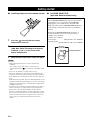 6
6
-
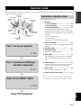 7
7
-
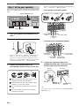 8
8
-
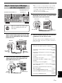 9
9
-
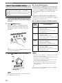 10
10
-
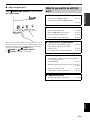 11
11
-
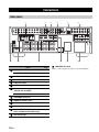 12
12
-
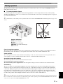 13
13
-
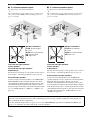 14
14
-
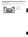 15
15
-
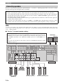 16
16
-
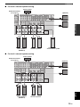 17
17
-
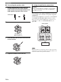 18
18
-
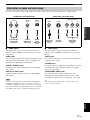 19
19
-
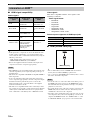 20
20
-
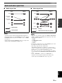 21
21
-
 22
22
-
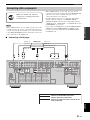 23
23
-
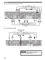 24
24
-
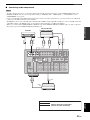 25
25
-
 26
26
-
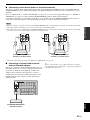 27
27
-
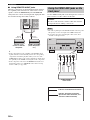 28
28
-
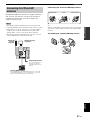 29
29
-
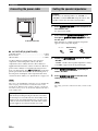 30
30
-
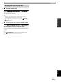 31
31
-
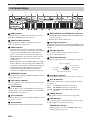 32
32
-
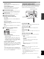 33
33
-
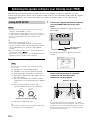 34
34
-
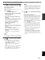 35
35
-
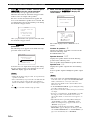 36
36
-
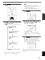 37
37
-
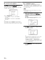 38
38
-
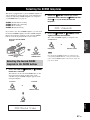 39
39
-
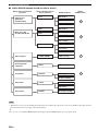 40
40
-
 41
41
-
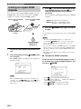 42
42
-
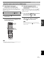 43
43
-
 44
44
-
 45
45
-
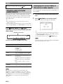 46
46
-
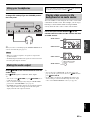 47
47
-
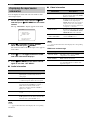 48
48
-
 49
49
-
 50
50
-
 51
51
-
 52
52
-
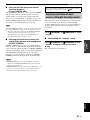 53
53
-
 54
54
-
 55
55
-
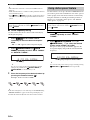 56
56
-
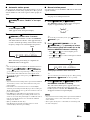 57
57
-
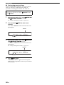 58
58
-
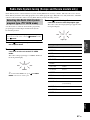 59
59
-
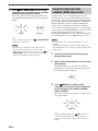 60
60
-
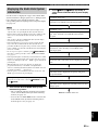 61
61
-
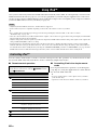 62
62
-
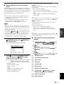 63
63
-
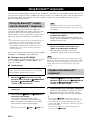 64
64
-
 65
65
-
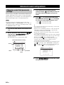 66
66
-
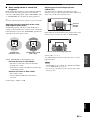 67
67
-
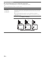 68
68
-
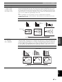 69
69
-
 70
70
-
 71
71
-
 72
72
-
 73
73
-
 74
74
-
 75
75
-
 76
76
-
 77
77
-
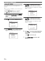 78
78
-
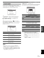 79
79
-
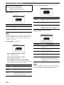 80
80
-
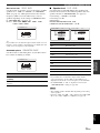 81
81
-
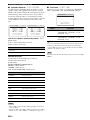 82
82
-
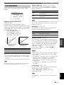 83
83
-
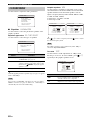 84
84
-
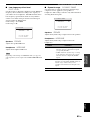 85
85
-
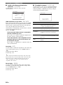 86
86
-
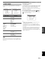 87
87
-
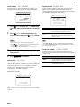 88
88
-
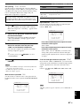 89
89
-
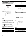 90
90
-
 91
91
-
 92
92
-
 93
93
-
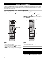 94
94
-
 95
95
-
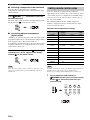 96
96
-
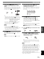 97
97
-
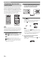 98
98
-
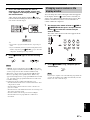 99
99
-
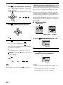 100
100
-
 101
101
-
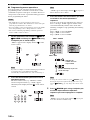 102
102
-
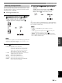 103
103
-
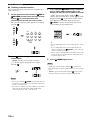 104
104
-
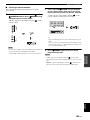 105
105
-
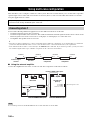 106
106
-
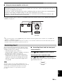 107
107
-
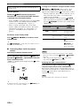 108
108
-
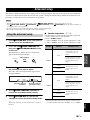 109
109
-
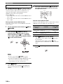 110
110
-
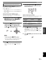 111
111
-
 112
112
-
 113
113
-
 114
114
-
 115
115
-
 116
116
-
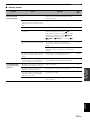 117
117
-
 118
118
-
 119
119
-
 120
120
-
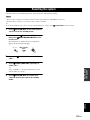 121
121
-
 122
122
-
 123
123
-
 124
124
-
 125
125
-
 126
126
-
 127
127
-
 128
128
-
 129
129
-
 130
130
-
 131
131
-
 132
132
-
 133
133
-
 134
134
-
 135
135
-
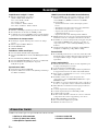 136
136
-
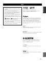 137
137
-
 138
138
-
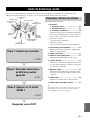 139
139
-
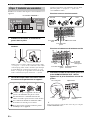 140
140
-
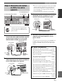 141
141
-
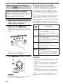 142
142
-
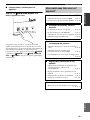 143
143
-
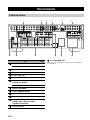 144
144
-
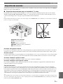 145
145
-
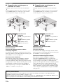 146
146
-
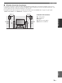 147
147
-
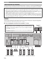 148
148
-
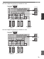 149
149
-
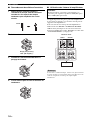 150
150
-
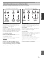 151
151
-
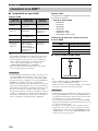 152
152
-
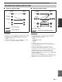 153
153
-
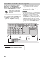 154
154
-
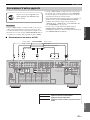 155
155
-
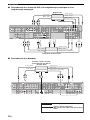 156
156
-
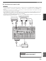 157
157
-
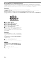 158
158
-
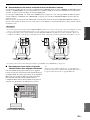 159
159
-
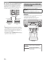 160
160
-
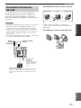 161
161
-
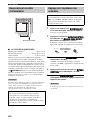 162
162
-
 163
163
-
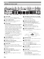 164
164
-
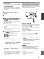 165
165
-
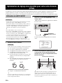 166
166
-
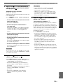 167
167
-
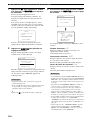 168
168
-
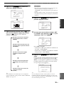 169
169
-
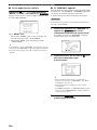 170
170
-
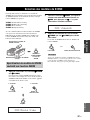 171
171
-
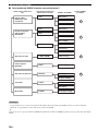 172
172
-
 173
173
-
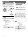 174
174
-
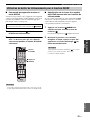 175
175
-
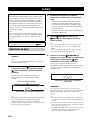 176
176
-
 177
177
-
 178
178
-
 179
179
-
 180
180
-
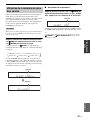 181
181
-
 182
182
-
 183
183
-
 184
184
-
 185
185
-
 186
186
-
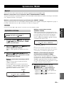 187
187
-
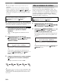 188
188
-
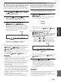 189
189
-
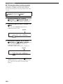 190
190
-
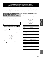 191
191
-
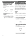 192
192
-
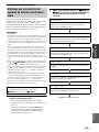 193
193
-
 194
194
-
 195
195
-
 196
196
-
 197
197
-
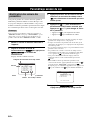 198
198
-
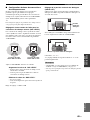 199
199
-
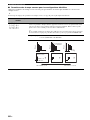 200
200
-
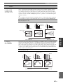 201
201
-
 202
202
-
 203
203
-
 204
204
-
 205
205
-
 206
206
-
 207
207
-
 208
208
-
 209
209
-
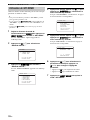 210
210
-
 211
211
-
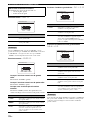 212
212
-
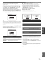 213
213
-
 214
214
-
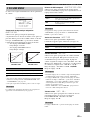 215
215
-
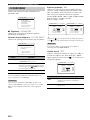 216
216
-
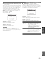 217
217
-
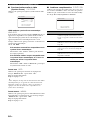 218
218
-
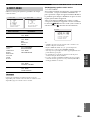 219
219
-
 220
220
-
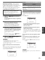 221
221
-
 222
222
-
 223
223
-
 224
224
-
 225
225
-
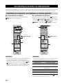 226
226
-
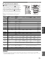 227
227
-
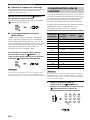 228
228
-
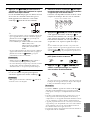 229
229
-
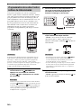 230
230
-
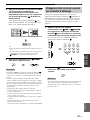 231
231
-
 232
232
-
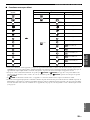 233
233
-
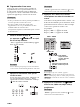 234
234
-
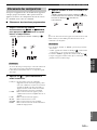 235
235
-
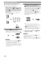 236
236
-
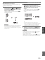 237
237
-
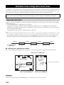 238
238
-
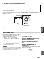 239
239
-
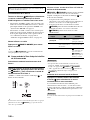 240
240
-
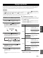 241
241
-
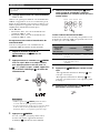 242
242
-
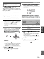 243
243
-
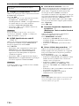 244
244
-
 245
245
-
 246
246
-
 247
247
-
 248
248
-
 249
249
-
 250
250
-
 251
251
-
 252
252
-
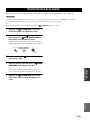 253
253
-
 254
254
-
 255
255
-
 256
256
-
 257
257
-
 258
258
-
 259
259
-
 260
260
-
 261
261
-
 262
262
-
 263
263
-
 264
264
-
 265
265
-
 266
266
-
 267
267
-
 268
268
-
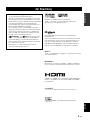 269
269
-
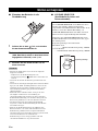 270
270
-
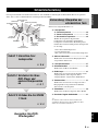 271
271
-
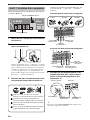 272
272
-
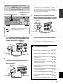 273
273
-
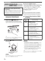 274
274
-
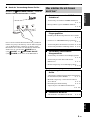 275
275
-
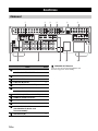 276
276
-
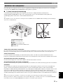 277
277
-
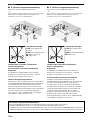 278
278
-
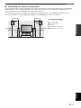 279
279
-
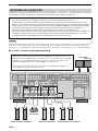 280
280
-
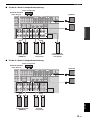 281
281
-
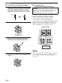 282
282
-
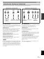 283
283
-
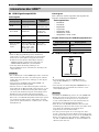 284
284
-
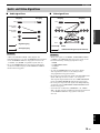 285
285
-
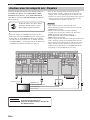 286
286
-
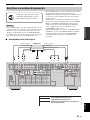 287
287
-
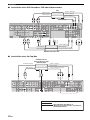 288
288
-
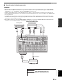 289
289
-
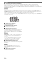 290
290
-
 291
291
-
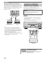 292
292
-
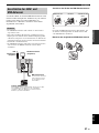 293
293
-
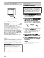 294
294
-
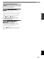 295
295
-
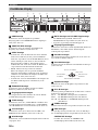 296
296
-
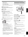 297
297
-
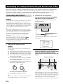 298
298
-
 299
299
-
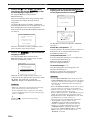 300
300
-
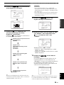 301
301
-
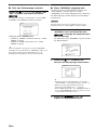 302
302
-
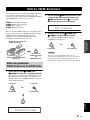 303
303
-
 304
304
-
 305
305
-
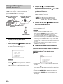 306
306
-
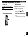 307
307
-
 308
308
-
 309
309
-
 310
310
-
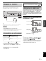 311
311
-
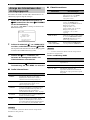 312
312
-
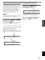 313
313
-
 314
314
-
 315
315
-
 316
316
-
 317
317
-
 318
318
-
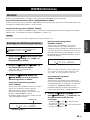 319
319
-
 320
320
-
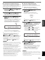 321
321
-
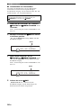 322
322
-
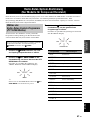 323
323
-
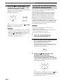 324
324
-
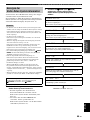 325
325
-
 326
326
-
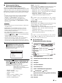 327
327
-
 328
328
-
 329
329
-
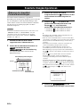 330
330
-
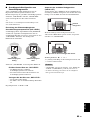 331
331
-
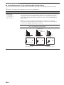 332
332
-
 333
333
-
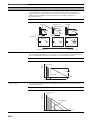 334
334
-
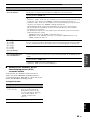 335
335
-
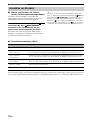 336
336
-
 337
337
-
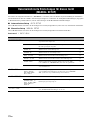 338
338
-
 339
339
-
 340
340
-
 341
341
-
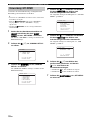 342
342
-
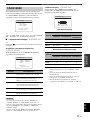 343
343
-
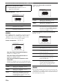 344
344
-
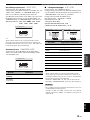 345
345
-
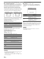 346
346
-
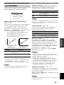 347
347
-
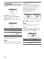 348
348
-
 349
349
-
 350
350
-
 351
351
-
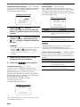 352
352
-
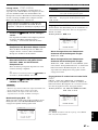 353
353
-
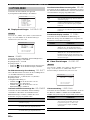 354
354
-
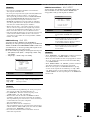 355
355
-
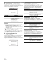 356
356
-
 357
357
-
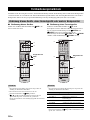 358
358
-
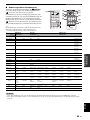 359
359
-
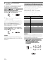 360
360
-
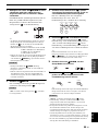 361
361
-
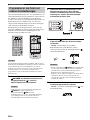 362
362
-
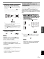 363
363
-
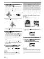 364
364
-
 365
365
-
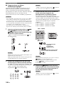 366
366
-
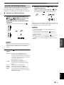 367
367
-
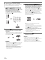 368
368
-
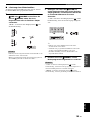 369
369
-
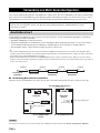 370
370
-
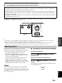 371
371
-
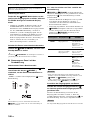 372
372
-
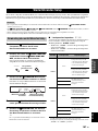 373
373
-
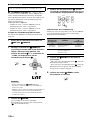 374
374
-
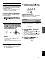 375
375
-
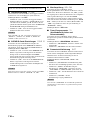 376
376
-
 377
377
-
 378
378
-
 379
379
-
 380
380
-
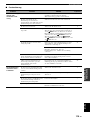 381
381
-
 382
382
-
 383
383
-
 384
384
-
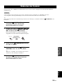 385
385
-
 386
386
-
 387
387
-
 388
388
-
 389
389
-
 390
390
-
 391
391
-
 392
392
-
 393
393
-
 394
394
-
 395
395
-
 396
396
-
 397
397
-
 398
398
-
 399
399
-
 400
400
-
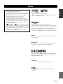 401
401
-
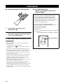 402
402
-
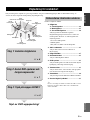 403
403
-
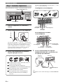 404
404
-
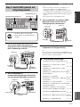 405
405
-
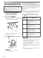 406
406
-
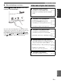 407
407
-
 408
408
-
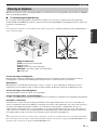 409
409
-
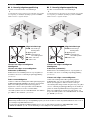 410
410
-
 411
411
-
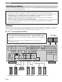 412
412
-
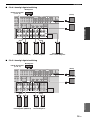 413
413
-
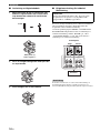 414
414
-
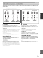 415
415
-
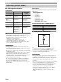 416
416
-
 417
417
-
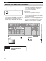 418
418
-
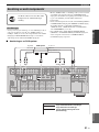 419
419
-
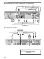 420
420
-
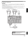 421
421
-
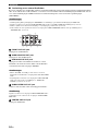 422
422
-
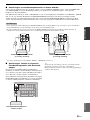 423
423
-
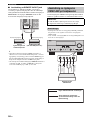 424
424
-
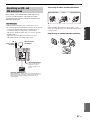 425
425
-
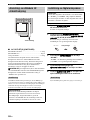 426
426
-
 427
427
-
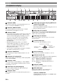 428
428
-
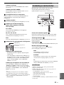 429
429
-
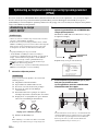 430
430
-
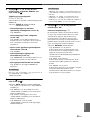 431
431
-
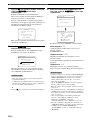 432
432
-
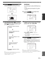 433
433
-
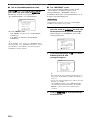 434
434
-
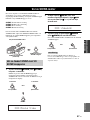 435
435
-
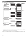 436
436
-
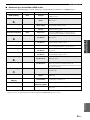 437
437
-
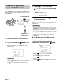 438
438
-
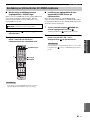 439
439
-
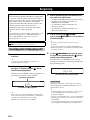 440
440
-
 441
441
-
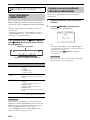 442
442
-
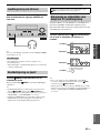 443
443
-
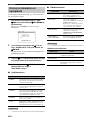 444
444
-
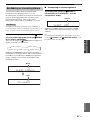 445
445
-
 446
446
-
 447
447
-
 448
448
-
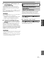 449
449
-
 450
450
-
 451
451
-
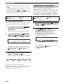 452
452
-
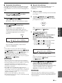 453
453
-
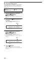 454
454
-
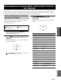 455
455
-
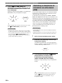 456
456
-
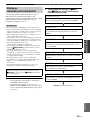 457
457
-
 458
458
-
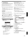 459
459
-
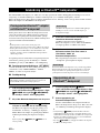 460
460
-
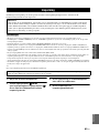 461
461
-
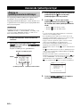 462
462
-
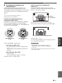 463
463
-
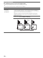 464
464
-
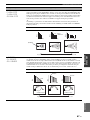 465
465
-
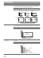 466
466
-
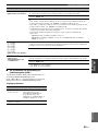 467
467
-
 468
468
-
 469
469
-
 470
470
-
 471
471
-
 472
472
-
 473
473
-
 474
474
-
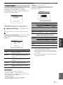 475
475
-
 476
476
-
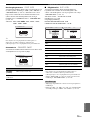 477
477
-
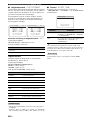 478
478
-
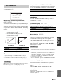 479
479
-
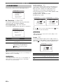 480
480
-
 481
481
-
 482
482
-
 483
483
-
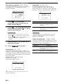 484
484
-
 485
485
-
 486
486
-
 487
487
-
 488
488
-
 489
489
-
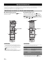 490
490
-
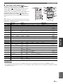 491
491
-
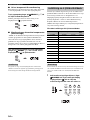 492
492
-
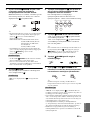 493
493
-
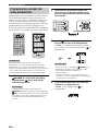 494
494
-
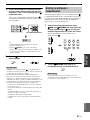 495
495
-
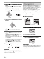 496
496
-
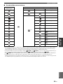 497
497
-
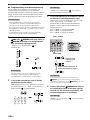 498
498
-
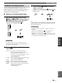 499
499
-
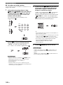 500
500
-
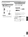 501
501
-
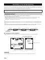 502
502
-
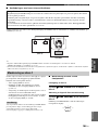 503
503
-
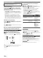 504
504
-
 505
505
-
 506
506
-
 507
507
-
 508
508
-
 509
509
-
 510
510
-
 511
511
-
 512
512
-
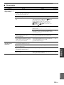 513
513
-
 514
514
-
 515
515
-
 516
516
-
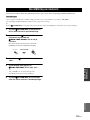 517
517
-
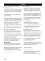 518
518
-
 519
519
-
 520
520
-
 521
521
-
 522
522
-
 523
523
-
 524
524
-
 525
525
-
 526
526
-
 527
527
-
 528
528
-
 529
529
-
 530
530
-
 531
531
-
 532
532
-
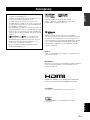 533
533
-
 534
534
-
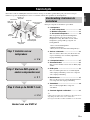 535
535
-
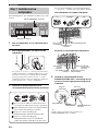 536
536
-
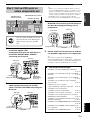 537
537
-
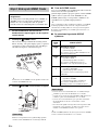 538
538
-
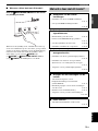 539
539
-
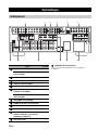 540
540
-
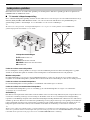 541
541
-
 542
542
-
 543
543
-
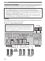 544
544
-
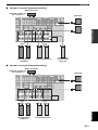 545
545
-
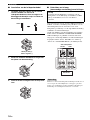 546
546
-
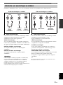 547
547
-
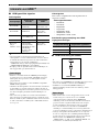 548
548
-
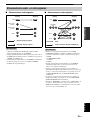 549
549
-
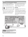 550
550
-
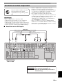 551
551
-
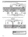 552
552
-
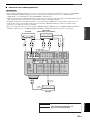 553
553
-
 554
554
-
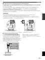 555
555
-
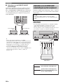 556
556
-
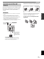 557
557
-
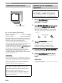 558
558
-
 559
559
-
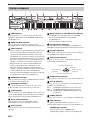 560
560
-
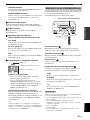 561
561
-
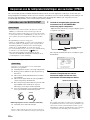 562
562
-
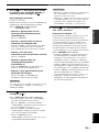 563
563
-
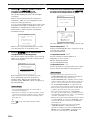 564
564
-
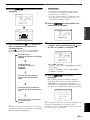 565
565
-
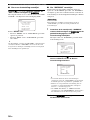 566
566
-
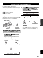 567
567
-
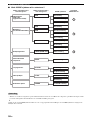 568
568
-
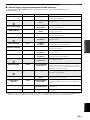 569
569
-
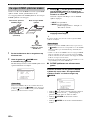 570
570
-
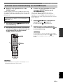 571
571
-
 572
572
-
 573
573
-
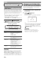 574
574
-
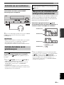 575
575
-
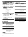 576
576
-
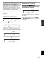 577
577
-
 578
578
-
 579
579
-
 580
580
-
 581
581
-
 582
582
-
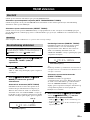 583
583
-
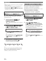 584
584
-
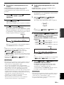 585
585
-
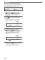 586
586
-
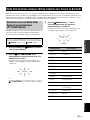 587
587
-
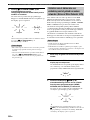 588
588
-
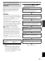 589
589
-
 590
590
-
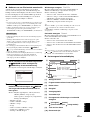 591
591
-
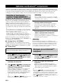 592
592
-
 593
593
-
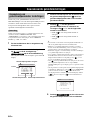 594
594
-
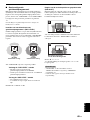 595
595
-
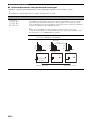 596
596
-
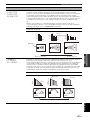 597
597
-
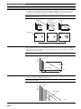 598
598
-
 599
599
-
 600
600
-
 601
601
-
 602
602
-
 603
603
-
 604
604
-
 605
605
-
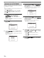 606
606
-
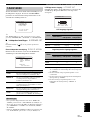 607
607
-
 608
608
-
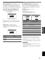 609
609
-
 610
610
-
 611
611
-
 612
612
-
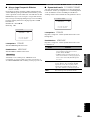 613
613
-
 614
614
-
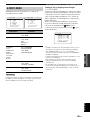 615
615
-
 616
616
-
 617
617
-
 618
618
-
 619
619
-
 620
620
-
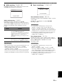 621
621
-
 622
622
-
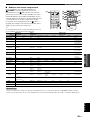 623
623
-
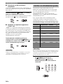 624
624
-
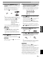 625
625
-
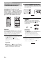 626
626
-
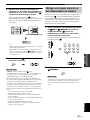 627
627
-
 628
628
-
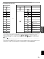 629
629
-
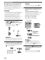 630
630
-
 631
631
-
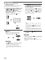 632
632
-
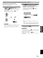 633
633
-
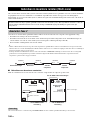 634
634
-
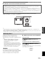 635
635
-
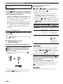 636
636
-
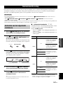 637
637
-
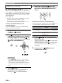 638
638
-
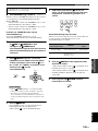 639
639
-
 640
640
-
 641
641
-
 642
642
-
 643
643
-
 644
644
-
 645
645
-
 646
646
-
 647
647
-
 648
648
-
 649
649
-
 650
650
-
 651
651
-
 652
652
-
 653
653
-
 654
654
-
 655
655
-
 656
656
-
 657
657
-
 658
658
-
 659
659
-
 660
660
-
 661
661
-
 662
662
-
 663
663
-
 664
664
-
 665
665
-
 666
666
-
 667
667
-
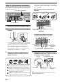 668
668
-
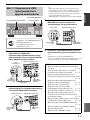 669
669
-
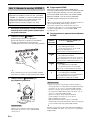 670
670
-
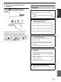 671
671
-
 672
672
-
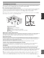 673
673
-
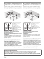 674
674
-
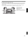 675
675
-
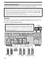 676
676
-
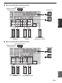 677
677
-
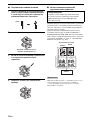 678
678
-
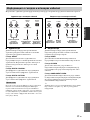 679
679
-
 680
680
-
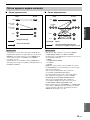 681
681
-
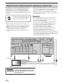 682
682
-
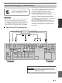 683
683
-
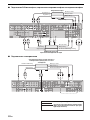 684
684
-
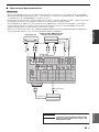 685
685
-
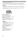 686
686
-
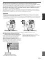 687
687
-
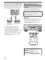 688
688
-
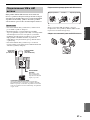 689
689
-
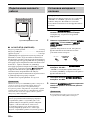 690
690
-
 691
691
-
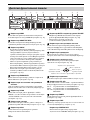 692
692
-
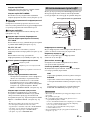 693
693
-
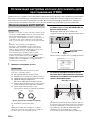 694
694
-
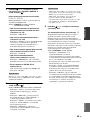 695
695
-
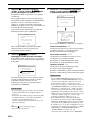 696
696
-
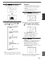 697
697
-
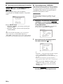 698
698
-
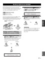 699
699
-
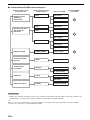 700
700
-
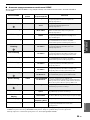 701
701
-
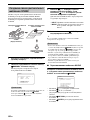 702
702
-
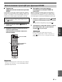 703
703
-
 704
704
-
 705
705
-
 706
706
-
 707
707
-
 708
708
-
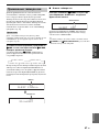 709
709
-
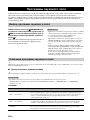 710
710
-
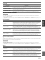 711
711
-
 712
712
-
 713
713
-
 714
714
-
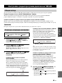 715
715
-
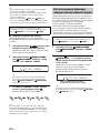 716
716
-
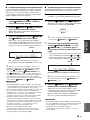 717
717
-
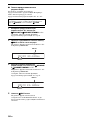 718
718
-
 719
719
-
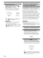 720
720
-
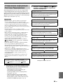 721
721
-
 722
722
-
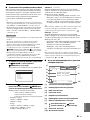 723
723
-
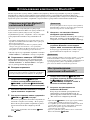 724
724
-
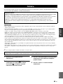 725
725
-
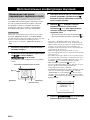 726
726
-
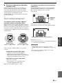 727
727
-
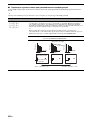 728
728
-
 729
729
-
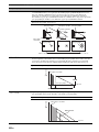 730
730
-
 731
731
-
 732
732
-
 733
733
-
 734
734
-
 735
735
-
 736
736
-
 737
737
-
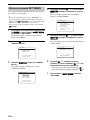 738
738
-
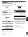 739
739
-
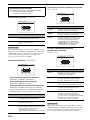 740
740
-
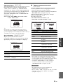 741
741
-
 742
742
-
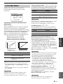 743
743
-
 744
744
-
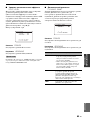 745
745
-
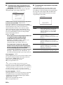 746
746
-
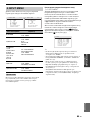 747
747
-
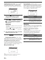 748
748
-
 749
749
-
 750
750
-
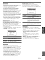 751
751
-
 752
752
-
 753
753
-
 754
754
-
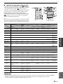 755
755
-
 756
756
-
 757
757
-
 758
758
-
 759
759
-
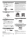 760
760
-
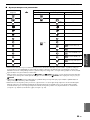 761
761
-
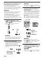 762
762
-
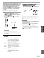 763
763
-
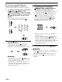 764
764
-
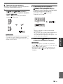 765
765
-
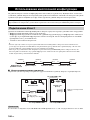 766
766
-
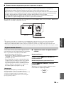 767
767
-
 768
768
-
 769
769
-
 770
770
-
 771
771
-
 772
772
-
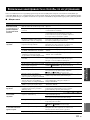 773
773
-
 774
774
-
 775
775
-
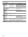 776
776
-
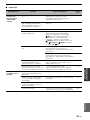 777
777
-
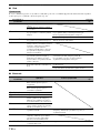 778
778
-
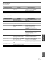 779
779
-
 780
780
-
 781
781
-
 782
782
-
 783
783
-
 784
784
-
 785
785
-
 786
786
-
 787
787
-
 788
788
-
 789
789
-
 790
790
-
 791
791
-
 792
792
-
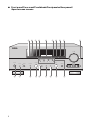 793
793
-
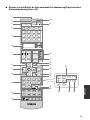 794
794
-
 795
795
-
 796
796
-
 797
797
-
 798
798
-
 799
799
-
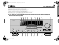 800
800
-
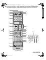 801
801


Yamaha RX-V863 Manualul proprietarului
- Categorie
- Receptoare AV
- Tip
- Manualul proprietarului
în alte limbi
- français: Yamaha RX-V863 Le manuel du propriétaire
- русский: Yamaha RX-V863 Инструкция по применению
- English: Yamaha RX-V863 Owner's manual
- suomi: Yamaha RX-V863 Omistajan opas
- Deutsch: Yamaha RX-V863 Bedienungsanleitung
- svenska: Yamaha RX-V863 Bruksanvisning
- dansk: Yamaha RX-V863 Brugervejledning
- Nederlands: Yamaha RX-V863 de handleiding