Yamaha NS-P440 Manualul proprietarului
- Categorie
- Difuzoare
- Tip
- Manualul proprietarului
Acest manual este potrivit și pentru

YAMAHA ELECTRONICS CORPORATION, USA
6660 ORANGETHORPE AVE., BUENA PARK, CALIF. 90620, U.S.A.
YAMAHA CANADA MUSIC LTD.
135 MILNER AVE., SCARBOROUGH, ONTARIO M1S 3R1, CANADA
YAMAHA ELECTRONIK EUROPA G.m.b.H.
SIEMENSSTR. 22-34, 25462 RELLINGEN BEI HAMBURG, GERMANY
YAMAHA ELECTRONIQUE FRANCE S.A.
RUE AMBROISE CROIZAT BP70 CROISSY-BEAUBOURG 77312 MARNE-LA-VALLEE CEDEX02, FRANCE
YAMAHA ELECTRONICS (UK) LTD.
YAMAHA HOUSE, 200 RICKMANSWORTH ROAD WATFORD, HERTS WD18 7GQ, ENGLAND
YAMAHA SCANDINAVIA A.B.
J A WETTERGRENS GATA 1, BOX 30053, 400 43 VÄSTRA FRÖLUNDA, SWEDEN
YAMAHA MUSIC AUSTRALIA PTY, LTD.
17-33 MARKET ST., SOUTH MELBOURNE, 3205 VIC., AUSTRALIA
©
2006 All rights reserved.
Printed in Indonesia WG63020
G
OWNER'S MANUAL
MODE D'EMPLOI
BEDIENUNGSANLEITUNG
BRUKSANVISNING
MANUALE DI ISTRUZIONI
MANUAL DE INSTRUCCIONES
GEBRUIKSAANWIJZING
NS-P440/
NS-P446
HOME CINEMA 5.1CH SPEAKER PACKAGE/
HOME CINEMA 6.1CH SPEAKER PACKAGE
(NS-P440/NS-P446: NX-E440 + NX-C440 +SW-P440)
000_cv_NS-P440_446_G.fm Page 1 Monday, November 28, 2005 8:28 PM

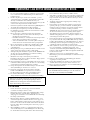
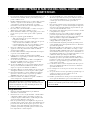
CAUTION: READ THIS BEFORE OPERATING YOUR UNIT.
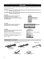
1 To assure the finest performance, please read this manual
carefully. Keep it in a safe place for future reference.
2 Install the speakers in a cool, dry, clean place – away from
windows, sources of heat, sources of excessive vibration,
dust, moisture or cold. Avoid sources of electrical humming
(e.g., transformers and motors). To prevent fire or electric
shock, do not expose the speakers to rain or water.
3 To prevent the enclosure from warping or discoloring, do not
expose the speakers to direct sunlight or excessive humidity.
4 Avoid installing the speakers where foreign objects may fall
onto them and/or where they may be exposed to liquid
dripping or splashing.
5 Do not place the following objects on top of the speakers:
– Other components, as they might damage or discolor the
surface of the speakers.
– Burning objects (e.g., candles), as they might cause fire,
damage to the speakers or personal injury.
– Containers of liquid, as they might spill and cause electric
shock to the user or damage to the speakers.
6 Do not place the speakers where they are liable to be knocked
over or struck by falling objects. Stable placement will also
ensure better sound.
7 Placing the speakers on the same shelf or rack as the
turntable can result in feedback.
8
Secure placement or installation is the owner’s responsibility.
YA M A H A
is not liable for accidents caused by improper
placement or installation of speakers.
9 If you note distortion, reduce the volume control on your
amplifier. Do not drive your amplifier to the point of
“clipping”. Otherwise, the speakers may be damaged.
10 When using an amplifier with a rated output power higher
than the nominal input power of the speakers, care should be
taken not to exceed the maximum input of the speakers.
11 Do not clean the speakers with chemical solvents as this
might damage the finish. Use a clean, dry cloth.
12 Do not attempt to modify or fix the speakers. Contact
qualified YAMAHA service personnel when service is
needed. Do not open the cabinet under any circumstances.
13 Please read the “Troubleshooting” section regarding common
operating errors before concluding that the speakers are
faulty.
For SW-P440
1 Do not operate this unit upside down. It may overheat, possibly
causing damage.
2 Do not use excessive force on switches, controls or connection
wires. When moving this unit, first disconnect the power plug
and the wires connected to other equipment. Never pull the wires
themselves.
3 Since this unit has a built-in power amplifier, heat radiates from
the rear panel. Place the unit away from walls, allowing at least
20 cm of space above, behind and on both sides of the unit to
prevent fire or damage. Furthermore, do not position the unit
with the rear panel facing down on the floor or other surfaces.
4 When using a humidifier, be sure to avoid condensation
inside this unit by allowing enough space around the unit and
avoiding excess humidification. Condensation might cause
fire, damage to the unit, and/or electric shock.
5 Do not cover the rear panel of this unit with a newspaper,
tablecloth, curtain, etc. to avoid obstructing heat radiation. If
the temperature inside the unit rises, it may cause fire,
damage to the unit, or personal injury.
6 Do not plug this unit into a wall outlet until all connections
are complete.
7 The voltage to be used must match that specified on the rear
panel. Using this unit with a voltage higher than specified is
dangerous and may cause fire, damage to the unit, and/or
personal injury. YAMAHA is not responsible for damage
resulting from use of this unit with a voltage other than
specified.
8 Super-bass sound reproduced by this unit may cause a
turntable to generate audio feedback. In this case, move the
unit away from the turntable.
9 This unit may be damaged if certain sounds are continuously
output at high volume level. For example, if 20Hz–50Hz sine
waves from a test disc or bass sounds from an electronic
instrument, etc. are continuously output, or if a turntable
stylus touches the surface of a disc, reduce the volume level
to prevent the unit from being damaged.
10 If you hear distorted noise (i.e., unnatural, intermittent
“rapping” or “hammering” sounds) from this unit, reduce the
volume level. Extremely loud movie soundtrack low
frequency, bass-heavy sounds, or similarly loud popular
music passages can damage this unit.
11 Vibration generated by super-bass sound may distort images
on a TV. In this case, move the unit away from the TV set.
12 When disconnecting the power cord from the wall outlet,
grasp the plug; do not pull the cord.
13 When you plan not to use this unit for a long period of time
(i.e. vacation, etc.), disconnect the AC power plug from the
wall outlet.
14 Install this unit near the wall outlet and where the AC power
plug can be reached easily.
CAUTION: READ THIS BEFORE OPERATING YOUR UNIT.
This unit features a magnetically shielded design, but there is
still a chance that placing it too close to a TV set might impair
picture color. Should this happen, move this unit away from
the TV set.
As long as this unit is connected to the AC wall outlet, it is
not disconnected from the AC power source even if you turn
off this unit by POWER.

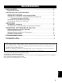
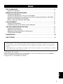
CONTENTS
1
English
GETTING STARTED . . . . . . . . . . . . . . . . . . . . . . . . . . . . . . . . . . . . . . . . . . . . . . . . 2
Supplied accessories . . . . . . . . . . . . . . . . . . . . . . . . . . . . . . . . . . . . . . . . . . . . . . . . . . . 2
SETTING UP THE SPEAKERS . . . . . . . . . . . . . . . . . . . . . . . . . . . . . . . . . . . . . . . 3
Placing speakers. . . . . . . . . . . . . . . . . . . . . . . . . . . . . . . . . . . . . . . . . . . . . . . . . . . . . . . 3
Mounting the speakers on the wall (NX-E440) . . . . . . . . . . . . . . . . . . . . . . . . . . . . . . . . 4
Installing the speakers on wall/ceiling brackets or speaker stands (NX-E440) . . . . . . . . 5
Placing the speaker (NX-C440) . . . . . . . . . . . . . . . . . . . . . . . . . . . . . . . . . . . . . . . . . . . 5
Placing the subwoofer (SW-P440) . . . . . . . . . . . . . . . . . . . . . . . . . . . . . . . . . . . . . . . . . 5
CONNECTIONS . . . . . . . . . . . . . . . . . . . . . . . . . . . . . . . . . . . . . . . . . . . . . . . . . . . 6
An example of connections . . . . . . . . . . . . . . . . . . . . . . . . . . . . . . . . . . . . . . . . . . . . . . . 6
Connecting the speaker cables and the subwoofer cable. . . . . . . . . . . . . . . . . . . . . . . . 7
USING THE SUBWOOFER (SW-P440) . . . . . . . . . . . . . . . . . . . . . . . . . . . . . . . . . 8
Controls and their functions . . . . . . . . . . . . . . . . . . . . . . . . . . . . . . . . . . . . . . . . . . . . . . 8
Adjusting the subwoofer . . . . . . . . . . . . . . . . . . . . . . . . . . . . . . . . . . . . . . . . . . . . . . . . . 8
Advanced Yamaha Active Servo Technology II. . . . . . . . . . . . . . . . . . . . . . . . . . . . . . . . . . . . . . . . 9
QD-BASS TECHNOLOGY . . . . . . . . . . . . . . . . . . . . . . . . . . . . . . . . . . . . . . . . . . . . . . . . . . . . . . . 9
TROUBLESHOOTING . . . . . . . . . . . . . . . . . . . . . . . . . . . . . . . . . . . . . . . . . . . . . . 10
SPECIFICATIONS. . . . . . . . . . . . . . . . . . . . . . . . . . . . . . . . . . . . . . . . . . . . . . . . . . 11
VOLTAGE SELECTOR
(For Asia and General models only)
The voltage selector switch on the rear panel of this unit must
be set for your local main voltage BEFORE plugging this unit
into the AC main supply.
Voltages are 110-120/220-240 V AC, 50/60 Hz
■ For U.K. customers
If the socket outlets in the home are not suitable for the
plug supplied with this appliance, it should be cut off and
an appropriate 3 pin plug fitted. For details, refer to
“SPECIAL INSTRUCTIONS FOR U.K. MODEL” on
this page.
The plug severed from the mains lead must be destroyed, as a
plug with bared flexible cord is hazardous if engaged in a live
socket outlet.
■ SPECIAL INSTRUCTIONS FOR U.K.
MODEL
CONTENTS
■ About this manual
• This manual is printed prior to production. Design and specifications are subject to change in part for the reason of
the improvements, etc. In this case, the product has priority.
• Some of the illustrations and names of the package contents, etc. written in this manual may differ from the actual
products and the names written on the package, etc.
Note
IMPORTANT:
THE WIRES IN MAINS LEAD ARE COLOURED IN
ACCORDANCE WITH THE FOLLOWING CODE:
Blue: NEUTRAL
Brown: LIVE
As the colours of the wires in the mains lead of this
apparatus may not correspond with the coloured
markings identifying the terminals in your plug,
proceed as follows:
The wire which is coloured BLUE must be connected
to the terminal which is marked with the letter N or
coloured BLACK. The wire which is coloured
BROWN must be connected to the terminal which is
marked with the letter L or coloured RED. Make sure
that neither core is connected to the earth terminal of
the three pin plug.

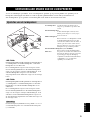
GETTING STARTED
2
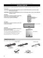
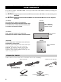
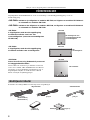
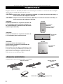
Thank you for selecting this YAM A HA NS-P440/NS-P446 Speaker Package.
The speaker package “NS-P440 and NS-P446” is designed for use in a multi-channel audio system such as a home
theater system.
<NS-P440> includes four NX-E440 speaker systems, one NX-C440 speaker system and one SW-
P440 subwoofer system.
<NS-P446> includes five NX-E440 speaker systems, one NX-C440 speaker system and one SW-P440
subwoofer system.
<NX-E440>
2-way acoustic-suspension speaker system used
for the front and surround speakers (and
surround center speaker for NS-P446)
<NX-C440>
2-way acoustic-suspension speaker system used
for the center speaker
<SW-P440>
Active Servo Processing Subwoofer System with
a built-in power amplifier
This subwoofer system employs Advanced Yamaha
Active Servo Technology which YAMAHA has developed
for reproducing higher quality super-bass sound (see
page 9). This super-bass sound adds a more realistic,
theater-in-the-home effect to your audio system.
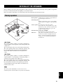
Please check to make sure all listed items are included.
GETTING STARTED
NX-E440
NX-C440
SW-P440
For front and
surround/surround
back speaker
For center speake
r
For subwoofer
Supplied accessories
Speaker cables Subwoofer cable
[4 m] x3
[5 m] x1
Non-skid pad x 1 set (4 pcs)
(for SW-P440)
Fasteners x2
(for NX-C440)
[15 m]
(for NS-P440 x2)
(for NS-P446 x3)

SETTING UP THE SPEAKERS
3
English
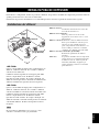
•
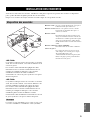
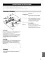
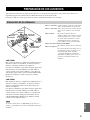
Before making connections, place all speakers in their respective positions. The positioning of the speakers is important
because it controls the whole sound quality of your audio system.
Place the speakers depending on your listening position by following the instructions below.
<NS-P440>
This speaker package employs a 6 speaker configuration:
2 front speakers, a center speaker, 2 surround speakers and
a subwoofer.
The front speakers carry most of the music/sound effects.
The center speaker emits center sound such as dialog, and
the surround speakers provide the surround/ambient
effects. The subwoofer adds the low-frequency bass
sound.
<NS-P446>
This speaker package employs a 7 speaker configuration:
2 front speakers, a center speaker, 2 surround speakers, a
surround center speaker and a subwoofer.
The front speakers carry most of the music/sound effects.
The center speaker emits center sound such as dialog, and
the surround and surround center speakers provide the
surround/ambient effects. The subwoofer adds the low-
frequency bass sound.
The same speakers (NX-E440) are used for the front and
surround speakers and surround center speakers (for NS-P446).
Front speakers: On both sides of your TV set. Approximately at
the same height as the TV set.
Surround speakers:
Behind your listening position, facing slightly
inward. About 1.8 m (approx. 6 feet) from the
floor.
Center speaker: Precisely between the front speakers.
You can place the center speaker on top of the
TV if the top is flat, on the floor under the TV,
or inside the TV rack. Be sure to place the
speaker in a stable position.
Surround center speaker (for NS-P446):
Precisely between the surround speakers.
Subwoofer: The position of the subwoofer is not so critical
because bass sound is not highly directional.
Refer to “Placing the subwoofer (SW-P440)”
on page 5 for a recommended positioning of
the subwoofer.
SETTING UP THE SPEAKERS
Placing speakers
Note
Front R
Center
Front L
Subwoofer
Surround center
(for NS-P446)
TV set
Surround L
Surround R

4
SETTING UP THE SPEAKERS
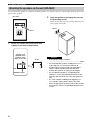
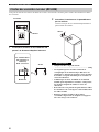
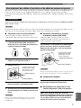
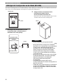
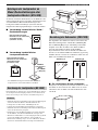
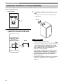
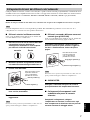
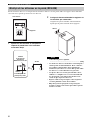
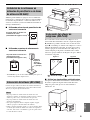
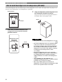
You can mount the speakers on a wall. To mount the speakers on a wall, use the holes of the brackets attached on the back
panels of the speakers.
1 Fasten two screws into a firm wall or wall
support at the interval shown below.
2 Hang the speaker by mounting the holes on
the protruding screws.
Make sure that the screws are securely affixed by the
narrow parts of the holes.
• Each speaker weighs as follows
........................................................................... 1.4 kg
• Do not mount the speakers on thin plywood or a
wall composed of a soft surface material. If
mounted, the screws may pull out of the flimsy
surface and the speakers may fall. This may
damage the speakers or cause personal injury.
• Do not affix the speakers to a wall using nails,
adhesives, or any other unstable hardware. Long-
term use and vibrations may cause the speakers to
fall.
• To avoid accidents resulting from tripping over
loose speaker cables, fix the cables to the wall.
• Select an appropriate position on the wall to mount
the speaker so that no one will injure his/her head
or face.
Mounting the speakers on the wall (NX-E440)
Rear view
Holes
Tapping screw
(Available at the
hardware store)
Diam. 3.5 to 4 mm
Min. 20 mm
Wall/Wall support
40 mm
4 mm
Caution
40 mm

5
SETTING UP THE SPEAKERS
English
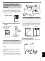
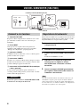
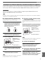
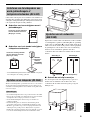
You can also use the screw holes on the rear panel or the
bottom of the speakers to install the speakers on
commercially available wall/ceiling brackets or speaker
stands (if you do not use the attached mounting brackets).
■ Using commercially available wall/
ceiling brackets
■ Using commercially available speaker
stands
*
The YAMAHA speaker stand SPS-30MMS may not be
available in some areas.
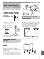
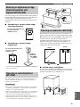
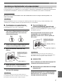
When placing the speaker on top of the TV rack, etc., attach the
provided fasteners at two points on the bottom of the speaker and
on the top of the TV.
• Do not place the center speaker on top of a TV whose area is
smaller than the bottom of the speaker. If placed, the speaker
may fall and cause injury.
• Do not place the center speaker on top of a TV if the top is
inclined.
• Do not touch the adhesive surface after peeling off the seal as
this will waken its adhesive strength.
• Thoroughly wipe clean the surface where the fastener is to be
applied. Note that adhesive strength is weakened if the surface
is dirty, oily or wet and that this may cause the center speaker to
fall.
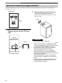
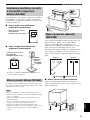
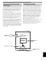
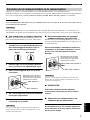
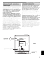
It is recommended to place the subwoofer on the outside
of either the right or the left front speaker (figure A). The
placement shown in figure B is also possible, however, if
the subwoofer is placed directly facing the wall, the bass
sound may lessen because the sound from the subwoofer
and the sound reflected by the wall may cancel out each
other. To prevent this from happening, face the subwoofer
obliquely to the wall.
■ Use the non-skid pads
Put the provided non-skid pads at the four corners on the
bottom of the subwoofer to prevent the subwoofer from
moving by vibrations, etc.
Installing the speakers on wall/
ceiling brackets or speaker stands
(NX-E440)
Placing the speaker (NX-C440)
Notes
A screw with a diameter of
6 mm can be used.
(Hole depth: 15 mm)
60 mm
Rear view
YAMAHA
Speaker stand
SPS-30MMS
(example)
A screw with a diameter of
4 mm can be used.
(Hole depth: 9 mm)
60 mm
Bottom view
Placing the subwoofer (SW-P440)
Peel off
the seal
Peel off
the seal
( : Subwoofer, : Front speakers)
Figure A
Figure B

CONNECTIONS
6
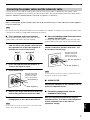
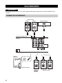
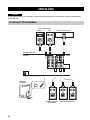
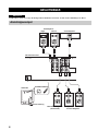
Plug in the subwoofer and other audio/video components after all connections are completed.
CONNECTIONS
Caution
An example of connections
SPEAKERS
MAIN
OUTPUT
SUB
WOOFER
CENTER
REAR CENTER
L
R
L
R
L
R
A
—
—
+
+
—
+
—
+
—
+
B
REAR
(SURROUND)
0 10
110V
–
120V 220V
–
240V
VOLTAGE
SELECTOR
VOLUME
INPUT
I
NPU
T
0 10
VOLUME
C
E
N
T
E
R
C
E
N
T
E
R
F
R
O
N
T
R
F
R
O
N
T
R
F
R
O
N
T
L
F
R
O
N
T
L
R
E
A
R
L
R
E
A
R
L
R
E
A
R R
R
E
A
R R
R
E
A
R
C
R
E
A
R
C
Amplifier/Receiver
Subwoofer
To AC outlet
Center speaker
Surround center
speaker
(for NS-P446)
Right
Left
Front speakers
Right
Left
Surround speakers

7
CONNECTIONS
English
Connect the front, center and surround speakers (and surround center speaker for NS-P446) to the speaker output
terminals of your amplifier/receiver with the provided speaker cables. The provided speaker cables have labels marked
FRONT L, FRONT R, CENTER, REAR L, REAR R (and REAR C for NS-P446).
Before connecting the speakers and the subwoofer, make sure that the power of the subwoofer and the amplifier/
receiver is turned off.
For connections, keep the speaker cables as short as possible. Do not bundle or roll up the excess part of the cables. If the
connections are faulty, no sound will be heard from the speakers.
■ Front speakers and Center speaker
Use the provided speaker cables (4 m). One side of the
speaker cable is red and the other side is black.
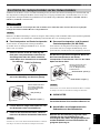
1 Remove approximately 10 mm of insulation
from the end of each speaker cable and twist
the exposed wires of the cable together to
eliminate the risk of a short-circuit.
2 Press and hold the tab of the terminal, as
shown in the figure of step 3.
3 Insert the bare wire.
4 Release your finger from the tab to allow it to
lock securely on the wire end of the cable.
5 Test the firmness of the connection by
pulling lightly on the cable at the terminal.
Do not let the bare speaker wires touch each other as this could
damage the speaker and/or the amplifier.
■ Surround speakers and Surround center
speaker (for NS-P446)
Use the provided speaker cables (15 m). One side of the
speaker cable has a gray line and the other side has no line.
The connection method is the same with Front
speakers and Center speaker. Read from 1 to 5
on left column on this page.
Do not let the bare speaker wires touch each other as this could
damage the speaker and/or the amplifier.
■ SUBWOOFER
Connect the subwoofer to the subwoofer pre out
jack of the amplifier/receiver.
■ Connecting components and the
subwoofer to AC plug
After you complete the connection, plug the
amplifier/receiver, TV or other outlet component
and the subwoofer into an AC outlet of
appropriate voltage.
Connecting the speaker cables and the subwoofer cable
Caution
Note
Note
G
ood
Not good
2
3
Red: positive (+)
Black: negative (–)
Note: Do not insert the
insulation coating into
the hole. The sound
may not be produced.
Note
2
3
Gray line: positive (+)
No line: negative (–)
Note: Do not insert the
insulation coating into
the hole. The sound
may not be produced.

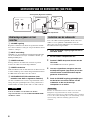
USING THE SUBWOOFER (SW-P440)
8
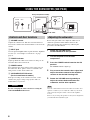
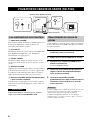
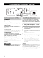
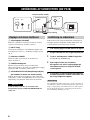
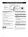
1 VOLUME control
Adjusts the volume level. Turn the control clockwise to
increase the volume and counterclockwise to decrease the
volume.
2 INPUT jack
Used to input unamplified bass signals from the amplifier/
receiver (see “An example of connections” on page
page 6).
3 POWER indicator
Lights up while the subwoofer is turned on and goes off
when the subwoofer is turned off.
4 POWER switch
Press inward to the ON position to turn on the power of
the subwoofer. Press again to release it outward to the
OFF position to turn off the subwoofer.
5 VOLTAGE SELECTOR switch
(For Asia and General models)
If the preset setting of the switch is incorrect, set the
switch to the proper voltage range (110 V-120 V or
220 V-240 V) of your area.
Be sure to unplug the subwoofer before setting the
VOLTAGE SELECTOR switch.
Before using the subwoofer, adjust the subwoofer to
obtain the optimum volume balance between the
subwoofer and the other speakers by following the
procedures described below.
1 Rotate the VOLUME control
counterclockwise to the 0 position.
2 Turn on the power of all the other
components.
3 Press the POWER switch inward to the ON
position.
The POWER indicator lights up.
4 Play a source that contains bass signal and
adjust the volume control of the amplifier/
receiver to the desired listening level.
5 Rotate the VOLUME control gradually to
adjust the volume balance between the
subwoofer and the other speakers.
Once the volume balance between the subwoofer and the other
speakers is adjusted, you can adjust the volume of your whole
audio system by using the volume control of the amplifier/
receiver.
However, if you change the speakers or the system configuration,
you must make this adjustment again.
USING THE SUBWOOFER (SW-P440)
0 10
110V
–
120V 220V
–
240V
VOLTAGE
SELECTOR
VOLUME
INPUT
P
O
W
E
R
O
N
O
FF
0 10
VOLUME INPUT
110V
–
120V 220V
–
240V
VOLTAGE
SELECTOR
12 3
4
5
Rear panel (General model)
To AC outlet
Controls and their functions
Caution
Adjusting the subwoofer
Note

9
USING THE SUBWOOFER (SW-P440)
English
In 1988, Yamaha brought to the speaker systems utilizing
YST (Yamaha Active Servo Technology) to give powerful,
high quality bass reproduction. This technology uses a
direct connection between the amplifier and speaker,
allowing accurate signal transmission and precise speaker
control.
As this technology uses speaker units controlled by the
negative impedance drive of the amplifier and resonance
generated between the cabinet capacity volume and port, it
creates more resonant energy (the “air woofer” concept)
than the standard bass reflex method. This allows for bass
reproduction from much smaller cabinets than was
previously possible.
Yamaha’s newly developed Advanced YST II adds many
refinements to Yamaha Active Servo Technology,
allowing better control of the forces driving the amplifier
and speaker. From the amplifier’s point of view, the
speaker impedance changes depending on the sound
frequency. Yamaha developed a new circuit design
combining negative-impedance and constant-current
drives, which provides a more stable performance and
clear bass reproduction without any murkiness.
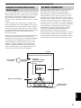
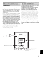
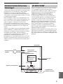
QD-BASS (Quatre Dispersion Bass) technology uses
down-firing drivers with square, pyramid-shaped
reflective plates to radiate the sound efficiently in four
horizontal directions. The reflective plates (not used in
competitors' down-firing subwoofers) negate any effects
caused by the floor surface and reduce resonance between
sound waves reflected from the floor and the unit. Also,
most other systems use circular cones, but by radiating in
four directions to avoid the legs of the cabinet, QD-BASS
reduces turbulence caused by reflection from the legs.
Changing the height of the square pyramid varies the
acoustic load, permitting relatively simple high-cut
adjustment and improved band pass properties.
The QD-BASS system provides extraordinary power and
smooth frequency response from an extremely compact
unit. It also allows greater freedom of placement, since the
sound radiates with equal effectiveness in all directions.
Advanced Yamaha Active Servo
Technology II
QD-BASS TECHNOLOGY
High-amplitude
bass sound
Port
Air woofer
(Helmholtz resonator)
Active Servo
Processing
Amplifier
Cabinet
Signals
Signals of low amplitude
Advanced Impedance
Converter
Pyramid-shaped
reflective plates

TROUBLESHOOTING
10
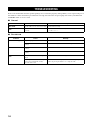
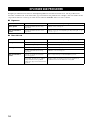
Refer to the chart below when this speaker package does not function properly. If the problem you are experiencing is not
listed below or if the instructions given below do not help, disconnect the AC power plug and contact your authorized
YAMAHA dealer or service center.
■ General
■ For
SW-P440
TROUBLESHOOTING
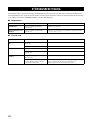
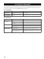
Problem Cause Remedy
No sound. Speaker cables are not connected securely. Connect them securely.
Sound level is too
low.
Speaker cables are not connected
correctly.
Connect them correctly, that is L (left) to L, R (right) to R, “+” to
“+” and “–” to “–”.
Problem Cause Remedy
Power is not supplied. The power plug is not connected securely. Connect it securely.
The POWER switch is set to the OFF
position.
Press the POWER switch inward to the ON position.
No sound. The VOLUME control is set to the 0
position.
Rotate the VOLUME control clockwise.
The subwoofer cables is not connected
securely.
Connect it securely.
Sound level is too
low.
A source that contains few bass signal is
played.
Play a source that contains bass signal.
“Standing waves” have been developed
between two parallel walls and they
cancel the bass sound.
Face the subwoofer obliquely to the wall or break up the parallel
surface by placing bookshelves, etc. along the walls.

SPECIFICATIONS
11
English
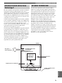
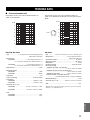
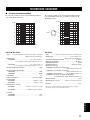
■ Frequency characteristics
The following graph displays the frequency characteristics
of the SW-P440 subwoofer.
The following graph displays the frequency characteristics
of the SW-P440 subwoofer combined with NX-E440
speakers.
NX-E440
, NX-C440
• Type ...................... 2-way acoustic-suspension speaker system
Magnetically shielded type
•Driver
<NX-E440> ......................................... 8 cm cone woofer x 1
2.5 cm balanced-dome tweeter x 1
<NX-C440>...........................................7 cm cone woofer x 2
2.5 cm balanced-dome tweeter x 1
• Nominal Input Power ................................................ 40 W
• Maximum Input Power
<NX-E440> ................................................................... 80 W
<NX-C440> ................................................................. 100 W
• Impedance .......................................................................... 6 Ω
• Frequency Response ................................... 65 Hz to 40 kHz
• Sensitivity
<NX-E440> .................................................. 80 dB/2.83 V/m
<NX-C440> .................................................. 82 dB/2.83 V/m
• Dimensions (W x H x D)
<NX-E440> ............................ 118 mm x 198 mm x 137 mm
<NX-C440> .............................. 285 mm x 99 mm x 130 mm
• Weight
<NX-E440> ................................................................. 1.4 kg
<NX-C440> ................................................................. 1.9 kg
SW-P440
• Type ............. Advanced Yamaha Active Servo Technology II
• Driver ................................................... 16 cm cone woofer
Magnetically shielded type
• Amplifier Output ................................................. 50 W/5 Ω
• Dynamic Power................................................. 100 W/5 Ω
• Input Impedance.............................................................12 KΩ
• Frequency Response ................................... 30 Hz to 180 Hz
• Power Supply
[U.S.A. and Canada models] .................. AC 120 V, 60 Hz
[U.K. and Europe models] ....................... AC 230 V, 50 Hz
[Australia model] ....................................... AC 240 V, 50 Hz
[Asia and General models]
........................................ AC 110-120/220-240 V, 50/60 Hz
• Power Consumption ....................................................... 45 W
• Dimensions (W x H x D) ......... 280 mm x 325 mm x 296 mm
• Weight ..................................................................... 8.2 kg
* Specifications are subject to change without notice due to product
improvements.
SPECIFICATIONS
20 50 100 200 500 Hz
40
50
60
70
80
90
100 dB
20 50 100 200 500 Hz
40
50
60
70
80
90
100 dB
SW-P440
NX-E440
V
O
L
UM
E

1
Pour profiter au mieux de votre acquisition, lisez attentivement ce
mode d’emploi. Conservez-le soigneusement pour référence.
2 Installez les enceintes dans un endroit frais, sec, loin des fenêtres
et des sources de chaleur et de vibration, des poussières, de
l’humidité et du froid. Évitez les sources de ronflements
électriques que sont les transformateurs et les moteurs. Pour
éviter les risques d’incendie et de secousses électriques,
n’exposez pas les enceintes à la pluie ni à l’humidité.
3 Pour éviter que la menuiserie des enceintes ne se déforme ou ne
se décolore, n’exposez pas les enceintes à la lumière directe du
soleil ni à une humidité excessive.
4 Évitez d’installer les enceintes dans un endroit exposé à la chute
d’objets ou encore à l’écoulement ou aux éclaboussures de
liquides.
5 Ne posez pas les objets suivants sur le dessus des enceintes:
– D’autres appareils qui pourraient endommager ou décolorer
la menuiserie des enceintes;
– Des objets enflammés (par exemple, des bougies) qui
pourraient endommager les enceintes, provoquer une
blessure, voire un incendie;
– Des récipients contenant des liquides qui pourraient se
renverser, endommager les enceintes ou être à l’origine d’une
secousse électrique.
6
Ne placez pas les enceintes dans un endroit où elles peuvent être
heurtées, directement ou par la chute d’objets. Un emplacement
stable garantit l’obtention de meilleures sonorités.
7 Placer les enceintes sur des étagères ou dans un meuble qui
contient également la platine de lecture, peut entraîner un
phénomène de bouclage.
8 La détermination d’un endroit convenable est de votre
responsabilité. YAMAHA ne saurait être responsable des accidents
provoqués par le choix d’un emplacement qui ne conviendrait pas,
ni par l’installation incorrecte des enceintes.
9
En cas de distorsion, réduisez le niveau de sortie de l’amplificateur.
N’excitez pas l’amplificateur au point qu’il écrête. Dans ce cas en
effet, les enceintes pourraient être endommagées.
10 Vous devez être très attentif, si l’amplificateur peut délivrer une
puissance supérieure à la puissance maximale admissible par les
enceintes, à ce que cela ne se produise pas.
11 Ne nettoyez pas la menuiserie des enceintes avec un produit
chimique qui peut endommager leur finition. Utilisez un chiffon
sec et propre.
12 Ne tentez pas de modifier les enceintes ni de les réparer.
Consultez le service YAMAHA compétent si une réparation est
nécessaire. Pour quelque raison que ce soit, ne démontez pas la
menuiserie des enceintes.
13 Prenez connaissance des erreurs fréquentes, mentionnées dans la
section “Guide de Dépannage”, avant de conclure que les
enceintes sont défectueuses.
En ce qui concerne le SW-P440
1 Ne le faites pas fonctionner à l’envers. Il peut surchauffer et être
endommagé.
2 Manœuvrez les commutateurs et les commandes avec précaution,
veillez aux câbles de liaison. Avant de déplacer cet appareil,
débranchez la fiche du cordon d’alimentation et les câbles qui le
relient aux autres appareils. Ne tirez pas sur les câbles.
3 Cet appareil étant doté d’un amplificateur de puissance, il
rayonne de la chaleur, à travers son panneau arrière. Placez cet
appareil loin des murs et ménagez au moins 20 cm au-dessus,
derrière et sur chaque côté pour réduire les risques d’incendie ou
d’endommagement. Par ailleurs, ne positionnez pas cet appareil
de telle manière que son panneau arrière soit tourné vers le
plancher ou en contact avec une paroi.
4 Si vous utilisez un humidificateur, veillez à réduire les risques de
condensation à l’intérieur de cet appareil en ménageant
suffisamment d’espace libre autour de lui et en réglant
l’humidificateur à une valeur convenable. La condensation peut
provoquer un incendie, endommager l’appareil et/ou être la cause
d’une secousse électrique.
5 Ne couvrez pas le panneau arrière d’un journal, d’une nappe,
d’un rideau, etc., ce qui pourrait empêcher la chaleur de
s’évacuer. Une augmentation anormale de la température
intérieure de l’appareil peut provoquer un incendie, endommager
l’appareil ou entraîner des blessures.
6 Ne branchez pas la fiche du cordon d’alimentation sur une prise
secteur aussi longtemps que tous les raccordements ne sont pas
terminés.
7 La tension à utiliser est indiquée sur le panneau arrière.
Alimenter cet appareil sous une tension supérieure à la tension
prescrite, peut provoquer un incendie, endommager l’appareil et/
ou entraîner des blessures. YAMAHA ne saurait être responsable
des dommages résultant de l’utilisation d’une tension
d’alimentation différente de la tension prescrite.
8 Le son à fréquences très graves produites par cet appareil peut
agir sur la platine de lecture et provoquer un bouclage. Dans ce
cas, éloignez l’appareil de la platine de lecture.
9 Cet appareil peut être endommagé par la production permanente
de certaines fréquences. Par exemple, si un signal sinusoïdal
entre 20 et 50 Hz est produit par un disque d’essai ou des sons
très graves sont générés par un instrument de musique
électronique, etc., ou encore si le saphir de la platine de lecture
frotte sur le microsillon, il sera bon de réduire le niveau de sortie
pour éviter les dommages.
10
Si vous notez que cet appareil produit de la distorsion (par
exemple, des bruits secs et répétés, un martèlement), réduisez le
niveau de sortie. Les fréquences très graves que contiennent
certaines pistes sonores de film ou certains passages de musique
populaire, peuvent endommager cet appareil.
11 Les vibrations produites par le son à fréquences très graves
peuvent déformer les images affichées sur le téléviseur. Dans ce
cas, éloignez l’appareil du téléviseur.
12 Pour débrancher la fiche du cordon d’alimentation, saisissez la
fiche mais ne tirez pas sur le cordon.
13
Si vous envisagez de ne pas utiliser cet appareil pendant une
longue période (par exemple, pendant des congés), débranchez la
fiche du cordon d’alimentation au niveau de la prise secteur.
14 Installez l’appareil près de la prise secteur et à un endroit tel que
la fiche secteur soit facilement accessible.
ATTENTION: VEUILLEZ LIRE CE QUI SUIT AVANT D’UTILISER L’APPAREIL.
Même si cette unité dispose d’une conception à blindage mag-
nétique, il y a un risque possible de création d’interférences,
visibles sur les images en couleurs si elle est placée à côté
d’un téléviseur. Dans ce cas, éloigner l’unité du téléviseur.
POUR LES CONSOMMATEURS CANADIENS
Pour éviter les chocs électriques, introduire la lame la plus
large de la fiche dans la borne correspondante de la prise
et pousser jusqu’au fond.
Cet appareil numérique de la classe B est conforme à la
norme NMB-003 du Canada.
Tant que l’appareil est raccordé à la prise secteur, il reste
connecté au secteur même si vous le mettez hors tension
avec POWER.

1
Français
POUR COMMENCER . . . . . . . . . . . . . . . . . . . . . . . . . . . . . . . . . . . . . . . . . . . . . . . 2
Accessoires fournis. . . . . . . . . . . . . . . . . . . . . . . . . . . . . . . . . . . . . . . . . . . . . . . . . . . . . 2
INSTALLATION DES ENCEINTES . . . . . . . . . . . . . . . . . . . . . . . . . . . . . . . . . . . . 3
Disposition des enceintes . . . . . . . . . . . . . . . . . . . . . . . . . . . . . . . . . . . . . . . . . . . . . . . . 3
Fixation des enceintes à un mur (NX-E440) . . . . . . . . . . . . . . . . . . . . . . . . . . . . . . . . . . 4
Installation des enceintes sur des fixations murales/pour plafond ou sur des pieds
d’enceinte (NX-E440) . . . . . . . . . . . . . . . . . . . . . . . . . . . . . . . . . . . . . . . . . . . . . . 5
Installation de l’enceinte (NX-C440) . . . . . . . . . . . . . . . . . . . . . . . . . . . . . . . . . . . . . . . . 5
Positionnement du caisson de graves (SW-P440) . . . . . . . . . . . . . . . . . . . . . . . . . . . . . 5
RACCORDEMENTS . . . . . . . . . . . . . . . . . . . . . . . . . . . . . . . . . . . . . . . . . . . . . . . . 6
Exemple de raccordements . . . . . . . . . . . . . . . . . . . . . . . . . . . . . . . . . . . . . . . . . . . . . . 6
Raccordement des câbles d’enceintes et du câble de caisson de graves . . . . . . . . . . . 7
UTILISATION DU CAISSON DE GRAVES (SW-P440) . . . . . . . . . . . . . . . . . . . . . 8
Les commandes et leurs fonctions . . . . . . . . . . . . . . . . . . . . . . . . . . . . . . . . . . . . . . . . . 8
Raccordement du caisson de graves . . . . . . . . . . . . . . . . . . . . . . . . . . . . . . . . . . . . . . . 8
Advanced Yamaha Active Servo Technology II . . . . . . . . . . . . . . . . . . . . . . . . . . . . . . . 9
QD-BASS TECHNOLOGIE. . . . . . . . . . . . . . . . . . . . . . . . . . . . . . . . . . . . . . . . . . . . . . . 9
GUIDE DE DÉPANNAGE . . . . . . . . . . . . . . . . . . . . . . . . . . . . . . . . . . . . . . . . . . . . 10
CARACTÉRISTIQUES TECHNIQUES . . . . . . . . . . . . . . . . . . . . . . . . . . . . . . . . . . 11
VOLTAGE SELECTOR (Sélecteur de tension)
(Modèle pour l’Asie et modèle standard seulement)
Le sélecteur de tension à l’arrière de cet appareil doit être réglé sur la tension secteur locale AVANT le raccordement de
l’appareil à une prise secteur.
La tension peut être réglée sur 110-120 V ou 220-240 V et 50 ou 60 Hz.
TABLE DES MATIÈRES
■ A propos de ce manuel
• L’impression de ce manuel est antérieure à la fabrication de ce produit. La conception et les spécifications sont
donc susceptibles d’être modifiées en vue de l’amélioration du produit ou pour d’autres raisons. Dans ce cas, le
produit est prioritaire.
• Certaines des illustrations et le contenu du carton indiqués dans ce manuel peuvent être différents, entre autre, des
produits proprement dits et des noms inscrits sur le carton d’emballage.

POUR COMMENCER
2
Merci d’avoir porté votre choix sur ce système acoustique YAMAHA NS-P440/NS-P446.
Les systèmes acoustiques “NS-P440 NS-P446” sont conçus pour les chaînes audio multivoies, utilisées par exemple pour
le cinéma à domicile.
Le <NS-P440> comprend quatre enceintes NX-E440, une enceinte NX-C440 et un caisson de graves
SW-P440.
Le <NS-P446> comprend cinq enceintes NX-E440, une enceinte NX-C440 et un caisson de graves
SW-P440.
<NX-E440>
Ces enceintes à 2 voies et à suspension
acoustique sont utilisées comme enceintes avant
et d’ambiance (et comme enceinte centrale pour
le système acoustique NS-P446).
<NX-C440>
Cette enceinte à 2 voies et à suspension
acoustique est utilisée comme enceinte centrale.
<SW-P440>
Caisson de graves à traitement servo actif avec
amplificateur de puissance
Ce caisson de graves intègre la toute dernière technologie
Advanced Yamaha Active Servo, mise au point par
YAMAHA, qui restitue des extrêmes graves de bien
meilleure qualité (voir page 9). Les extrêmes graves
rendent les effets cinématographiques restitués par votre
chaîne encore plus réalistes.
Veuillez vérifier si tous les articles cités se trouvent bien dans le carton d’emballage.
POUR COMMENCER
NX-E440
NX-C440
SW-P440
Pour les enceintes
avant et d’ambiance/
d’ambiance arrière
Pour l’enceinte
centrale
Pour le caisson de
graves
Accessoires fournis
Câbles d’enceinte Câble de caisson de graves
[4 m] x3
[5 m] x1
Patin anti-vibratoire x 1 jeu (4 pièces)
(pour le SW-P440)
Fixations x2
(pour le NX-C440)
[15 m]
(pour le NS-P440 x2)
(pour le NS-P446 x3)

INSTALLATION DES ENCEINTES
3
Français
•
Avant de raccorder toutes les enceintes, installez-les à leur place respective. La position des enceintes est importante
parce qu’elle détermine la qualité générale du son de la chaîne.
Disposez vos enceintes de la façon suivante en tenant compte de votre position d’écoute.
<NS-P440>
Ce système acoustique consiste en 6 enceintes: 2 enceintes
avant, une enceinte centrale, 2 enceintes d’ambiance et un
caisson de graves.
Les enceintes avant transmettent la plupart des effets
musicaux/sonores. L’enceinte centrale transmet la voie
centrale, par exemple les dialogues, et les enceintes
d’ambiance fournissent les effets d’ambiance/
environnants. Le caisson de graves ajoute des sons graves
de basse fréquence.
<NS-P446>
Ce système acoustique consiste en 7 enceintes: 2 enceintes
avant, une enceinte centrale, 2 enceintes d’ambiance, une
enceinte d’ambiance centrale et un caisson de graves.
Les enceintes avant transmettent la plupart des effets
musicaux/sonores. L’enceinte centrale transmet la voie
centrale, par exemple les dialogues, et les enceintes
d’ambiance plus l’enceinte d’ambiance centrale
fournissent les effets d’ambiance/environnants. Le caisson
de graves ajoute des sons graves de basse fréquence.
Les mêmes enceintes (NX-E440) servent comme enceintes avant
et enceintes
d’ambiance et d’ambiance centrale (NS-P446).
Enceintes avant: De part et d’autre du téléviseur. À peu près à
la même hauteur que le téléviseur.
Enceintes arrière: Derrière votre position d’écoute, orientée
légèrement vers l’intérieur de la pièce. A
environ 1,8 m du sol.
Enceinte centrale:
Précisément entre les deux enceintes avant.
Vous pouvez installer l’enceinte centrale sur
un téléviseur à condition que le haut soit plat,
sur le sol sous le téléviseur, ou bien dans le
meuble du téléviseur. L’enceinte doit être bien
stable.
Enceinte d’ambiance centrale (NS-P446):
Précisément entre les enceintes d’ambiance.
Caisson de graves:
La position du caisson de graves n’est pas
aussi critique car le son des graves est peu
directionnel. Reportez-vous à
“Positionnement du caisson de graves (SW-
P440)” à la page 5 pour le positionnement
idéal du caisson de graves.
INSTALLATION DES ENCEINTES
Disposition des enceintes
Remarque
Avant D
Centre
Avant G
Caisson de
graves
Ambiance centre
(NS-P446)
Téléviseur
Ambiance G
Ambiance D

4
INSTALLATION DES ENCEINTES
Vous pouvez fixer les enceintes à un mur. Pour ce faire, accrochez les enceintes par les orifices des fixations à l’arrière
des enceintes.
1 Vissez deux vis dans un mur solide ou une
poutre à la distance indiquée ci-dessous.
2 Accrochez l’enceinte aux vis protubérantes
par les orifices.
Assurez-vous que les vis sont bien bloquées dans la
partie étroite des orifices.
• Chaque enceinte a le poids suivant
........................................................................... 1,4 kg
• Ne suspendez pas les enceintes à un mur en
contreplaqué ou en matériau léger. Sinon, les vis
risquent de se détacher de la surface et les enceintes
de tomber. Ceci peut endommager les enceintes ou
causer des blessures.
• N’utilisez pas de clous, d’adhésif ou de matériel
instable pour suspendre les enceintes. A long terme,
les enceintes risquent de tomber à cause des
vibrations.
• Pour éviter de vous prendre les pieds dans les câbles
des enceintes et de vous exposer à un accident, fixez
les câbles au mur.
• Fixez les enceintes au mur à une position
convenable où personne ne risque de se frapper la
tête ou le visage et de se blesser.
Fixation des enceintes à un mur (NX-E440)
Vue arrière
Orifices
Vis autotaraudeuse
(En vente dans le
commerce)
Diam. 3,5 à 4 mm
Min. 20 mm
Mur/Poutre
40 mm
4 mm
Avertissement
40 mm

5
INSTALLATION DES ENCEINTES
Français
Les orifices à l’arrière ou sous les enceintes peuvent aussi être
utilisés pour suspendre les enceintes sur des fixations murales/
pour plafond ou les installer sur des pieds d’enceintes (si vous
ne voulez pas utiliser les fixations fournies).
■ Utilisation de fixations murales/pour
plafond en vente dans le commerce
■ Utilisation de pieds d’enceintes en vente
dans le commerce
*
Le pied d’enceinte YAMAHA SPS-30MMS peut ne pas être
commercialisé dans certains pays.
Si vous installez l’enceinte sur le téléviseur, etc. collez les
fixations fournies à deux endroits sous l’enceinte et sur le
téléviseur.
• N’installez pas l’enceinte centrale sur le téléviseur si le panneau
supérieur est plus étroit que le dessous de l’enceinte. L’enceinte
risquerait sinon de tomber et de causer des blessures.
• N’installez pas l’enceinte centrale sur le téléviseur si le panneau
supérieur est incliné.
• Ne touchez pas les surfaces de l’adhésif après avoir enlevé les
feuilles de protection car elles seront moins adhérentes.
• Essuyez bien la surface à l’endroit approprié avant de coller les
fixations. Les fixations seront moins adhérentes si la surface est
sale, grasse ou humide, et l’enceinte centrale risque de tomber.
Il est conseillé d’installer le caisson de graves sur le côté
extérieur de l’enceinte droite ou gauche (figure A). Il est
également possible de l’installer comme indiqué sur la
figure B, mais s’il est placé directement face au mur, les
sons graves risquent d’être affaiblis, parce que le son émis
par le caisson et le son réfléchi par le mur risquent de
s’annuler réciproquement. Pour pallier ce problème,
mettez le caisson de graves à l’oblique du mur.
■ Utilisation des patins anti-vibratoires
Collez les patins anti-vibratoires fournis aux quatre coins
sous le caisson de graves pour empêcher le caisson de
bouger sous l’effet des vibrations, etc.
Installation des enceintes sur des
fixations murales/pour plafond ou
sur des pieds d’enceinte (NX-E440)
Installation de l’enceinte
(NX-C440)
Remarques
Une vis de 6 mm de diamètre
peut être utilisée.
(Profondeur de l’orifice: 15 mm)
60 mm
Vue arrière
Pied
d’enceinte
YAMAHA
SPS-30MMS
(exemple)
Une vis de 4 mm de diamètre
peut être utilisée.
(Profondeur de l’orifice: 9 mm)
60 mm
Vue de dessous
Positionnement du caisson de
graves (SW-P440)
Retirez la
feuille de
protection
Retirez la
feuille de
protection
( : Caisson de graves, : Enceinte avant)
Figure A
Figure B

RACCORDEMENTS
6
Raccordez le caisson de graves et les autres appareils audio/vidéo lorsque tous les autres branchements sont
terminés.
RACCORDEMENTS
Avertissement
Exemple de raccordements
SPEAKERS
MAIN
OUTPUT
SUB
WOOFER
CENTER
REAR CENTER
L
R
L
R
L
R
A
—
—
+
+
—
+
—
+
—
+
B
REAR
(SURROUND)
0 10
110V
–
120V 220V
–
240V
VOLTAGE
SELECTOR
VOLUME
INPUT
I
NPU
T
0 10
VOLUME
C
E
N
T
E
R
C
E
N
T
E
R
F
R
O
N
T
R
F
R
O
N
T
R
F
R
O
N
T
L
F
R
O
N
T
L
R
E
A
R
L
R
E
A
R
L
R
E
A
R R
R
E
A
R R
R
E
A
R
C
R
E
A
R
C
Amplificateur/Ampli-tuner
Caisson
de graves
À une prise secteur
Enceinte centrale
Enceinte
d’ambiance
centrale
(NS-P446)
Droite
Gauche
Enceinte avant
Droite
Gauche
Enceintes arrière
Pagina se încarcă...
Pagina se încarcă...
Pagina se încarcă...
Pagina se încarcă...
Pagina se încarcă...
Pagina se încarcă...
Pagina se încarcă...
Pagina se încarcă...
Pagina se încarcă...
Pagina se încarcă...
Pagina se încarcă...
Pagina se încarcă...
Pagina se încarcă...
Pagina se încarcă...
Pagina se încarcă...
Pagina se încarcă...
Pagina se încarcă...
Pagina se încarcă...
Pagina se încarcă...
Pagina se încarcă...
Pagina se încarcă...
Pagina se încarcă...
Pagina se încarcă...
Pagina se încarcă...
Pagina se încarcă...
Pagina se încarcă...
Pagina se încarcă...
Pagina se încarcă...
Pagina se încarcă...
Pagina se încarcă...
Pagina se încarcă...
Pagina se încarcă...
Pagina se încarcă...
Pagina se încarcă...
Pagina se încarcă...
Pagina se încarcă...
Pagina se încarcă...
Pagina se încarcă...
Pagina se încarcă...
Pagina se încarcă...
Pagina se încarcă...
Pagina se încarcă...
Pagina se încarcă...
Pagina se încarcă...
Pagina se încarcă...
Pagina se încarcă...
Pagina se încarcă...
Pagina se încarcă...
Pagina se încarcă...
Pagina se încarcă...
Pagina se încarcă...
Pagina se încarcă...
Pagina se încarcă...
Pagina se încarcă...
Pagina se încarcă...
Pagina se încarcă...
Pagina se încarcă...
Pagina se încarcă...
Pagina se încarcă...
Pagina se încarcă...
Pagina se încarcă...
Pagina se încarcă...
Pagina se încarcă...
Pagina se încarcă...
Pagina se încarcă...
Pagina se încarcă...
Pagina se încarcă...
Pagina se încarcă...
-
 1
1
-
 2
2
-
 3
3
-
 4
4
-
 5
5
-
 6
6
-
 7
7
-
 8
8
-
 9
9
-
 10
10
-
 11
11
-
 12
12
-
 13
13
-
 14
14
-
 15
15
-
 16
16
-
 17
17
-
 18
18
-
 19
19
-
 20
20
-
 21
21
-
 22
22
-
 23
23
-
 24
24
-
 25
25
-
 26
26
-
 27
27
-
 28
28
-
 29
29
-
 30
30
-
 31
31
-
 32
32
-
 33
33
-
 34
34
-
 35
35
-
 36
36
-
 37
37
-
 38
38
-
 39
39
-
 40
40
-
 41
41
-
 42
42
-
 43
43
-
 44
44
-
 45
45
-
 46
46
-
 47
47
-
 48
48
-
 49
49
-
 50
50
-
 51
51
-
 52
52
-
 53
53
-
 54
54
-
 55
55
-
 56
56
-
 57
57
-
 58
58
-
 59
59
-
 60
60
-
 61
61
-
 62
62
-
 63
63
-
 64
64
-
 65
65
-
 66
66
-
 67
67
-
 68
68
-
 69
69
-
 70
70
-
 71
71
-
 72
72
-
 73
73
-
 74
74
-
 75
75
-
 76
76
-
 77
77
-
 78
78
-
 79
79
-
 80
80
-
 81
81
-
 82
82
-
 83
83
-
 84
84
-
 85
85
-
 86
86
-
 87
87
-
 88
88


Yamaha NS-P440 Manualul proprietarului
- Categorie
- Difuzoare
- Tip
- Manualul proprietarului
- Acest manual este potrivit și pentru
în alte limbi
- Türkçe: Yamaha NS-P440 El kitabı
- français: Yamaha NS-P440 Le manuel du propriétaire
- русский: Yamaha NS-P440 Инструкция по применению
- English: Yamaha NS-P440 Owner's manual
- suomi: Yamaha NS-P440 Omistajan opas
- Deutsch: Yamaha NS-P440 Bedienungsanleitung
- italiano: Yamaha NS-P440 Manuale del proprietario
- español: Yamaha NS-P440 El manual del propietario
- svenska: Yamaha NS-P440 Bruksanvisning
- dansk: Yamaha NS-P440 Brugervejledning
- Nederlands: Yamaha NS-P440 de handleiding
Lucrări înrudite
-
Yamaha NS-P440 Manualul proprietarului
-
Yamaha NS-P436 Manualul proprietarului
-
Yamaha NS-P210 Manualul proprietarului
-
Yamaha NS-P220 Manualul proprietarului
-
-
-
-
-
Yamaha NS-P320 Manualul proprietarului
-